Slide Scanner Service
For technicians!
The service program
(SlideScannerService.exe; SSS) is an essential tool to setup, install and test
the scanners P250, Pannoramic SCAN,
The description of the tools
and options is based on the software version 1.17 and 1.18.
· Differences
according to the actual scanner and special dialogues are explained separately.
For
safety regulations regarding human health and scanner functionality please
refer to: Precautions

Contents
Section [Microscope] of MicroscopeConfiguration.ini
· Execute the
brightfield preview calibration
· Execute the
darkfield preview calibration (P250, PCON)
· Move the units of
the scanner on a low level
· Test and check
values of connected units
· Define and check
hardware limits
· Move the units in
a defined number of cycles or endless
· Clear the EEPROM
The following
list contains the path and locations of probably required files in different
operating systems and development stages of the scan program.
In software versions with the operating
system Windows® 7 x 64bit (since 2011)
MicroscopeConfiguration.ini and MicroscopeSettings.ini
· C:\ProgramData\3DHISTECH\SlideScanner\
Service program and scan program
· C:\Program
Files\3DHISTECH\SlideScanner\SlideScannerService.exe
· C:\Program
Files\3DHISTECH\SlideScanner\SlideScanner.exe
License file for the service program
· C:\Program Files\3DHISTECH\SlideScanner\MService.lic
In software versions with the operating
system Windows® XP x 32bit (2009 and later)
MicroscopeConfiguration.ini
and MicroscopeSettings.ini
· C:\DocumentsAndSettings\AllUsers\ApplicationData\3DHISTECH\SlideScanner\
Service program and scan program
· C:\Program
Files\3DHISTECH\SlideScanner\SlideScannerService.exe
· C:\Program
Files\3DHISTECH\SlideScanner\SlideScanner.exe
License file for the service program
· C:\Program Files\3DHISTECH\SlideScanner\MService.lic
In early software
versions with the operating system Windows® XP x 32bit (2009 and before)
tdhmic_Config.ini and tdhmic_Settings.ini
· C:\Program Files\MIRAXSCAN\
Service program and scan program
· C:\Program Files\MIRAXSCAN\MService.exe
· C:\Program Files\MIRAXSCAN\MScan.exe
License file for the service program
· C:\Program Files\MIRAXSCAN\MService.lic
Setup
“SlideScannerService.exe”
The service program will be
installed automatically during the installation of the scan program
“SlideScanner.exe”; see also: “Setup the scan
program”.
 Attention: Do not mix the versions of SlideScanner.exe and the
version of SlideScannerService.exe! Always use these programs with the same
version number; otherwise the program SlideScannerService.exe could produce
unwanted results and SlideScanner.exe does not work correctly or even freeze!
Attention: Do not mix the versions of SlideScanner.exe and the
version of SlideScannerService.exe! Always use these programs with the same
version number; otherwise the program SlideScannerService.exe could produce
unwanted results and SlideScanner.exe does not work correctly or even freeze!
· This is important for the options
“Brightfield preview calibration” and “Darkfield preview calibration” because
these options using *.dll-files of the SlideScanner software. The options
“Clear EEPROM” and “LowLevelService” working independent of the program
SlideScanner.exe; therefore, if these options are used only, the version number
is less important.
Requirements and start
the service program
·  Valid license file: “MService.lic”
in the folder: C:\Program Files\3DHISTECH\SlideScanner\
Valid license file: “MService.lic”
in the folder: C:\Program Files\3DHISTECH\SlideScanner\
· Before starting the software “SlideScannerService”, the USB driver has
to be installed!
· Start the program “SlideScannerService.exe” by clicking the icon
“SlideScannerService.exe” or from its folder.
For the actual path
(folder) of the service program please refer to “Paths and locations”
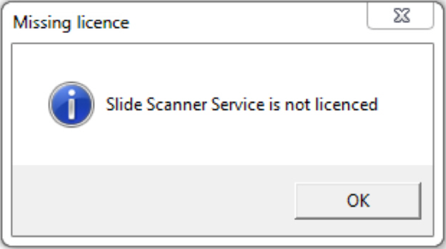 If the license file is
not recognized or invalid, a message “Missing license” is displayed.
If the license file is
not recognized or invalid, a message “Missing license” is displayed.
· Please check the presence of the license file; see “Paths and locations”
· Please check the validity of the license file
Check the validity of the license file
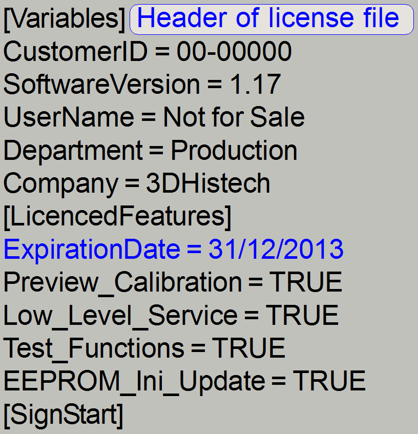
Open the license file
MService.lic with any text editor (e.g. Notepad or WordPad) and check:
· the expiration
date and
· licensed options
To avoid confusion, the
scanner type is recognized automatically by the service program (and the scan
program of course) during start up; only the tools, needed for the appropriate,
connected scanner can be reached; see also the parameter ”MicroscopeType” in the section [Microscope] of the file “MicroscopeConfiguration.ini”.
The found parameter value in
the found “MicroscopeConfiguration.ini” decides the available options.
The microscope type is
checked during the start of the service program and is true for all options of
the selector menu; especially important in the “Low Level Service” part.
The
microscope type can be
MicroscopeType=
3DMic4 MIRAX SCAN microscopes before
the year 2006; equipped with the preview camera “Logitech QC
4000 pro”.
3DMic5 MIRAX DESK and Pannoramic DESK
3DMic6 MIRAX SCAN, the magazine has 50 slide
positions and is equipped with the preview camera “DFK 21F04”
3DMic7 MIRAX MIDI and Pannoramic
3DMic8 SCAN 150 (MIRAX SCAN upgraded to magazines
with 25 slide positions) and Pannoramic SCAN
3DMic9 Pannoramic 250 (P250)
3DMIC10 MIDI_II; Pannoramic MIDI modular; (with
objective changer); see also: “Focus
unit OC”
3DMIC11 SCAN_II; Pannoramic SCAN modular; (with
objective changer); see also: “Focus
unit OC”
3DMIC12 DESK_II
Preview Calibration
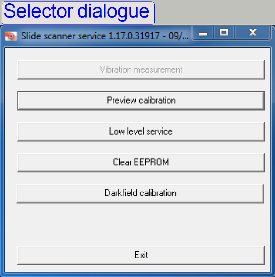 This part of the
service program is an interactive tool and calculates the physical position (distance)
of the preview camera in relation to the scan (main) camera.
This part of the
service program is an interactive tool and calculates the physical position (distance)
of the preview camera in relation to the scan (main) camera.
More, detailed information can be found in the chapter
S_M_D: “Preview
S_M_D” and “Steps
of preview calibration”
P250: “P250_preview”
and “Brightfield
preview calibration procedure”
Low Level Service
This part of the program
allows the handling of the components in a very high degree of freedom; see later in this
description.
Clear EEPROM
This option clears the EEPROM
content.
The EEPROM stores the scanner specific parameters and these are
collected in the files “MicroscopeConfiguration.ini” and “MicroscopeSettings.ini”
as well. To ensure an always proper function of the scanner, the content of the
EEPROM should be updated after adjustments are done or units are exchanged and
parameter values are modified.
·
To update the content, the EEPROM must be cleared
first; see also: “Clear the EEPROM”.
Darkfield calibration
This option uses a software
algorithm to calibrate the darkfield preview.
Please refer to the chapters
“Darkfield
preview”, “Darkfield
preview calibration” and “Calibrate
the darkfield preview”
Exit
This is leaving the service program.
 Answer the question
with “Yes”.
Answer the question
with “Yes”.
· If the scan
software “SlideScanner.exe” is started and the EEPROM is empty, the content of
the appropriate *.ini files is written automatically from the actual folder of
the HDD into the EEPROM, during the startup procedure of the program
“SlideScanner.exe”.
· The
path of the *.ini-files, used to update the EEPROM in the version with the
operating system Windows® 7 is:
C:\ProgramData\3DHISTECH\SlideScanner\MicroscopeConfiguration.ini
and MicroscopeSettings.ini
· In the
version with the operating system Windows® xP is:
C:\ Documents and Settings\All
Users\ApplicationData\3DHISTECH\SlideScanner\MicroscopeConfiguration.ini and
MicroscopeSettings.ini
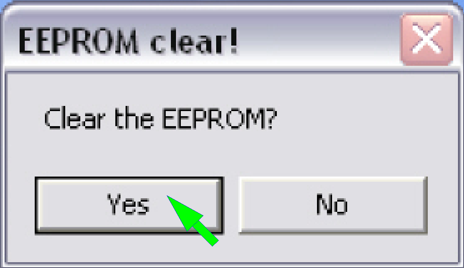
1.
Start the program “SlideScannerService.exe”, option
“Clear EEPROM”.
2.
Answer the dialogue with “Yes”; then the EEPROM is
cleared.
3.
Leave the selector dialog with “Exit”
4.
Start the program SlideScanner.exe; the *.ini-files
will be saved automatically from the appropriate HDD folder into the EEPROM
during startup the program, if the EEPROM is empty.
![]() ”EEPROM”
”EEPROM”
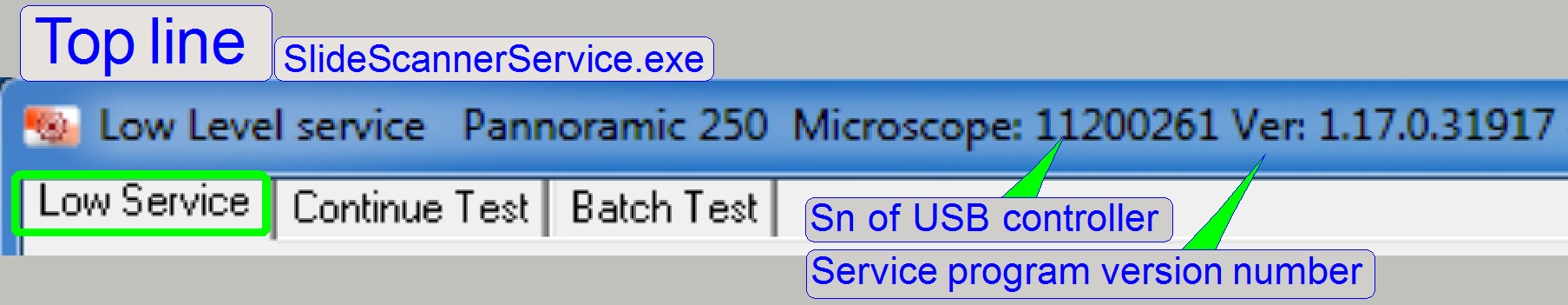 After selecting
the option “Low Level Service = LLS” the connected scanner type (Pannoramic 250),
the serial number of the connected USB controller (11200261) and the version
number of the service program (1.17.0.31917) is shown in the top line. The
scanner type is derived from the found “MicroscopeConfiguration.ini” file; see
also above “Scanner types”
After selecting
the option “Low Level Service = LLS” the connected scanner type (Pannoramic 250),
the serial number of the connected USB controller (11200261) and the version
number of the service program (1.17.0.31917) is shown in the top line. The
scanner type is derived from the found “MicroscopeConfiguration.ini” file; see
also above “Scanner types”
The upper half of the screen
contains the usual options like “X-Motor”, “Y-Motor”, “Focus-Motor” and
“Turret-Motor” tools, during the lower half of the screen contains scanner
specific units like DC controller, Objective changer and other special tools.
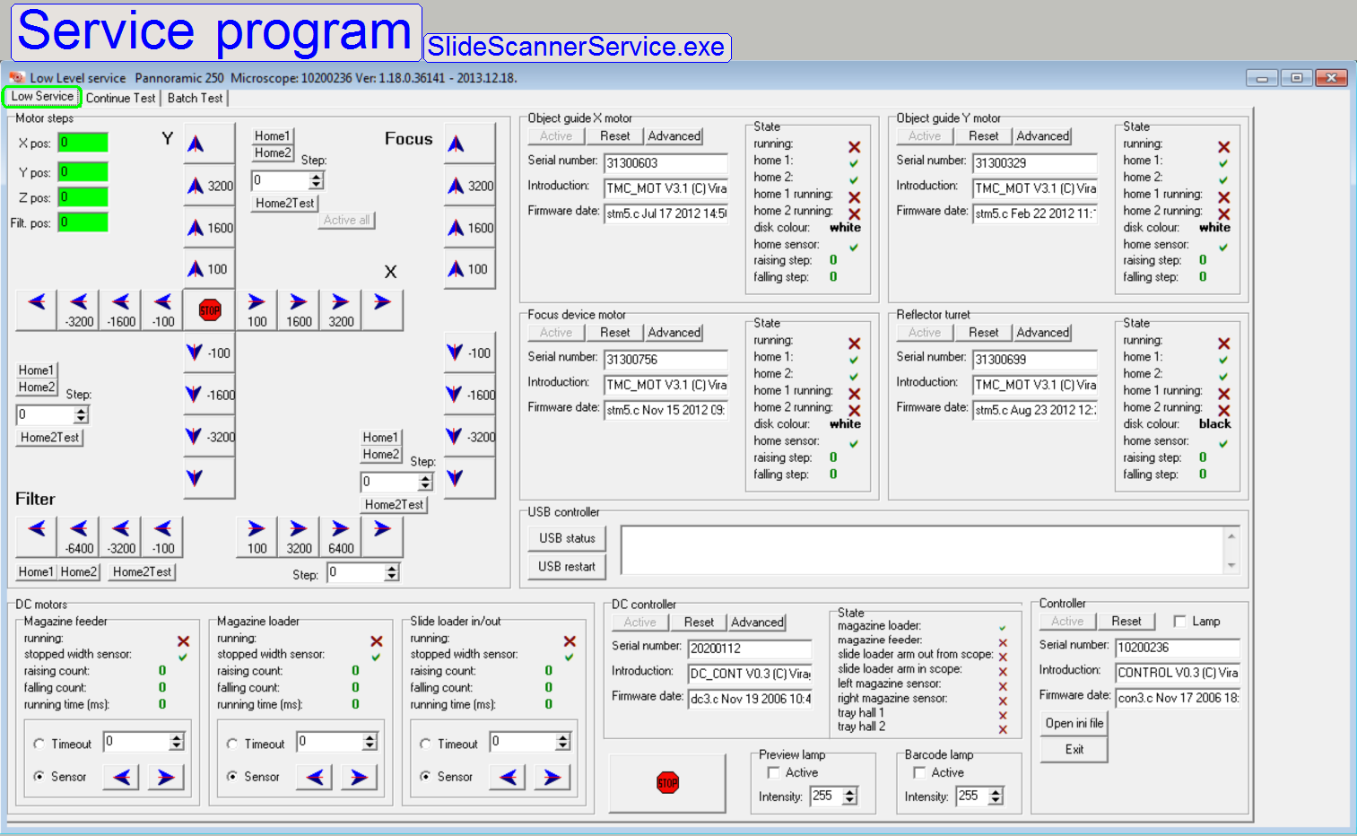 All the units of the scanner can be driven
independently from each other; the technician defines the action without limits
(the limits are given by the hardware limits of the construction).
All the units of the scanner can be driven
independently from each other; the technician defines the action without limits
(the limits are given by the hardware limits of the construction).
· Because the
sensors are handled in polling mode, the different units of the scanner may be
connected or disconnected (can be switched active or inactive (Reset))
separately to save execution and response time.
Important
To
spend a very high degree of freedom for the Low Level Service part of the
program, only small software protections are implemented (and in addition,
these can be overridden)!
The
technician has to select carefully the action to be executed, otherwise units
might be damaged, bend or made unusable.
The Low Level Service
includes:
·
Set the stepper motors to Home1,2.
·
Check the functionality of the sensor Home2.
·
Move any stepper motor a predefined or user defined number
of steps; forward or backward respectively.
·
Showing always the actual rotor position in steps,
proceeded from Home1,2.
·
Driving the DC-motor's rotor forward or backward as
desired for the action requested; the stop event may be:
- The sensor
action or
- The predefined runtime evaluated (named as
Timeout)
·
Showing always the actual state of the sensors.
·
Switching on or off illuminations
·
USB status monitoring
·
Checking and monitoring the status of the unit,
defined as “active”
·
Displays the serial number and the electronics version
number of the connected unit
·
Stop of all movements in emergency situations.
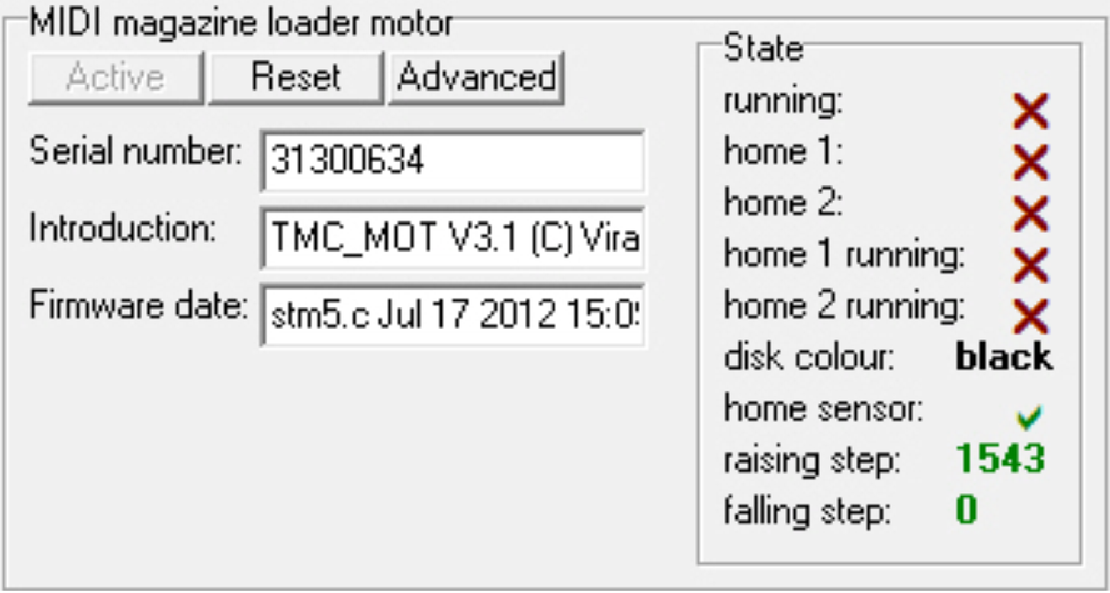
Active
 Allows the use of
the appropriate unit and switches it into the active state. The service program
starts the communication with the motor or unit electronics. During this action
the serial number of the motor and the firmware version with date is read out
from the motor electronics.
Allows the use of
the appropriate unit and switches it into the active state. The service program
starts the communication with the motor or unit electronics. During this action
the serial number of the motor and the firmware version with date is read out
from the motor electronics.
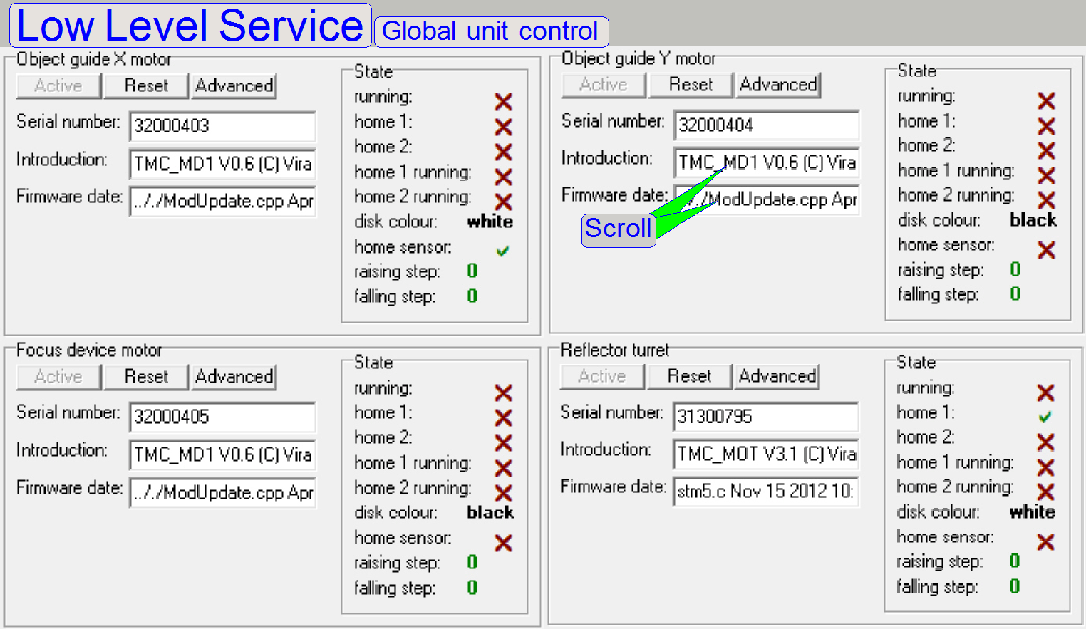
By dragging or scrolling in
the alphanumeric field the not shown part of the content can be displayed.
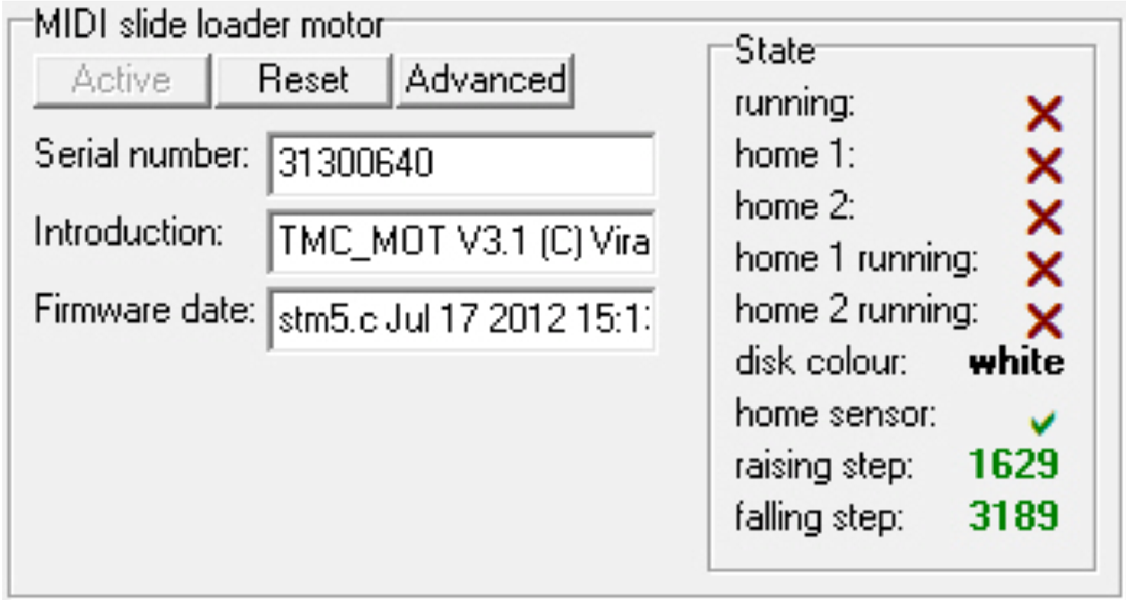
State
On the right hand side of the
appropriate unit, the current position of the sensors Home1 and Home2 are
shown; for information about the stepper motors and the sensors Home 1 and
Home2 please refer also to the chapter “Stepper motor
implementation” in the file “USB- and
DC-controlling” and “Sensor
Home1” and the hardware limits”.
Reset
Is used to switch inactive
the appropriate unit if it’s not in use; so the response time of the other,
active units is reduced.
Advanced
A dialogue with special
parameters of the unit will be opened.
This option is used in
special conditions only; the default values are meeting almost always the setup
conditions. Exceptions will be discussed separately; in the part of the
appropriate unit.
 In any cases, if
mechanical jamming occurs, all actions in progress are stopped.
In any cases, if
mechanical jamming occurs, all actions in progress are stopped.
·
Press this button if any action has to be stopped in
emergency situations.
·
The “Emergency power off” (P250) or the power switch
for the power supply (S_M_D) can also be used to abort any movements.
![]() Important “TaskManager”
Important “TaskManager”
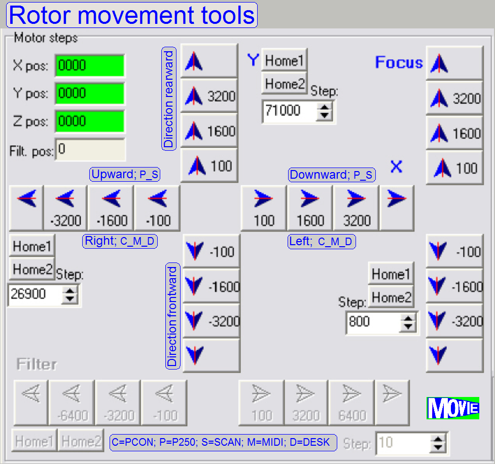
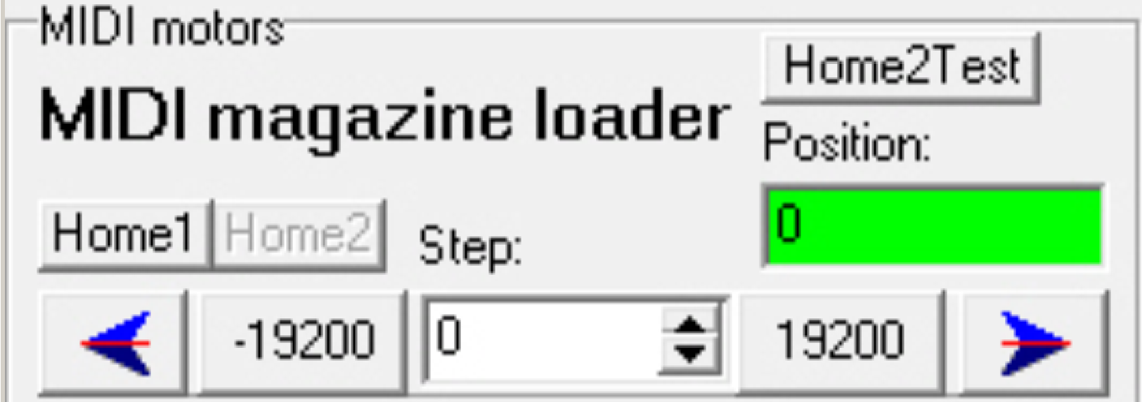
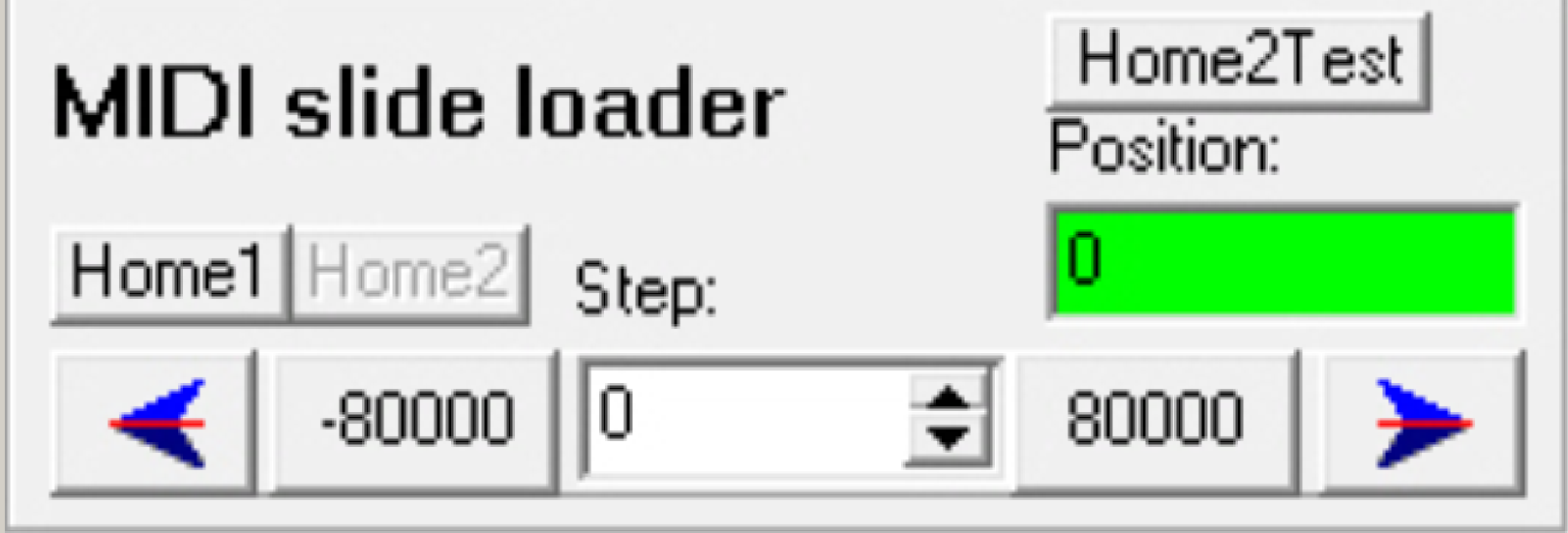
The movement of the stepper
motor’s rotor is realized with predefined step
number buttons.
·  In special conditions, and to
reach any required position, the user can also define a number of
steps to go, any time.
In special conditions, and to
reach any required position, the user can also define a number of
steps to go, any time.
Motor steps
The actual position of the
rotor is shown in a number of steps in distance to the position Home1,2.
If the appropriate unit is
active, the content of the step counter is shown; see also “Motor steps”.
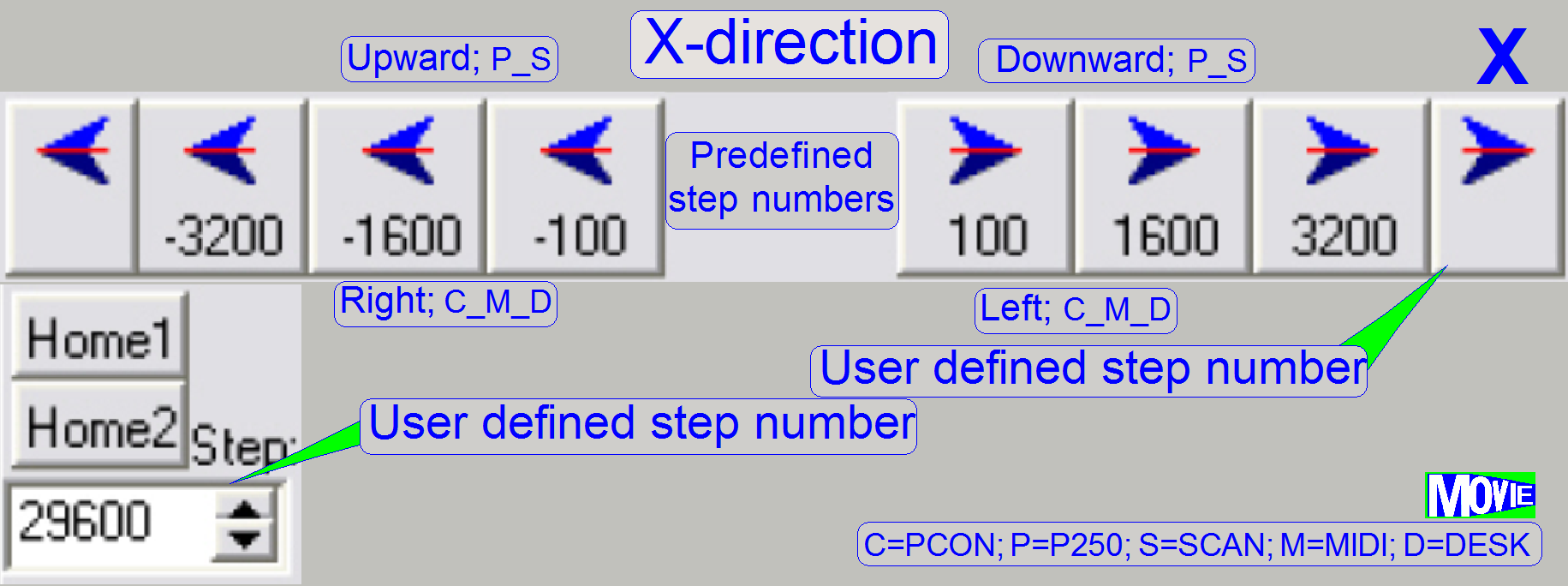
X-direction
The buttons are arranged
horizontally like the mathematical X-axis; ; see also “X-direction tools”.
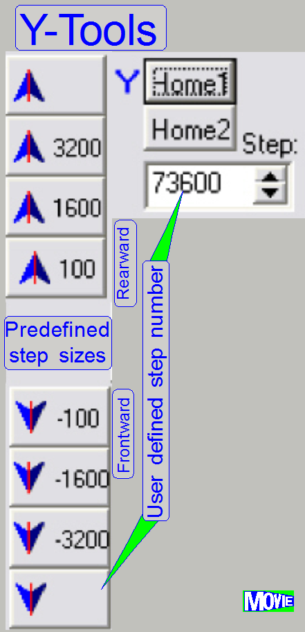
Y-direction
The buttons are arranged
vertically like the mathematical Y-axis; see also “Y-direction tools”.
Activate all
All the motors and
controllers are switched to the active state. This action is identical with the
procedure to press the button “Active” for each unit separately.
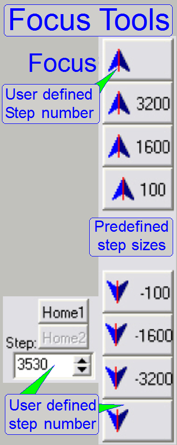
Focus
The nominal center of the
focus range is exactly 1600steps (in S_M_D) ; see also “Focus motor tools”.
Filter
The filter wheel of the
reflector turret unit is driven by the use of these buttons.
The distance of two filter
positions is exactly 6400steps in the gear driven RTU; see also “FL reflector turret tools”.
Home1, Home2
By pressing the button Home1,
the rotor finds the start position inside of 1 revolution.
By pressing the button Home2,
the entire mechanical drive is moved to its home position and by pressing the
button Home2 second time, the step counter will be cleared.
See also “Home1,2”.
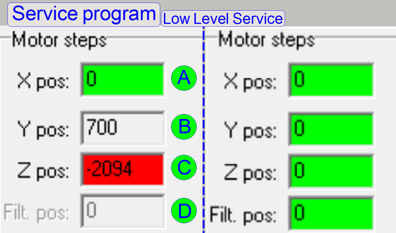 This part shows the step counter content of
the appropriate motor.
This part shows the step counter content of
the appropriate motor.
· In this part the
actual position of the rotor is shown for the stepper motors.
· If positive
numbers are shown, the position of the rotor is identical with the step counter
content.
· Negative numbers
showing always the step counter content as a deviation in steps from the
Home1,2 state in negative direction.
· If the appropriate
motor is switched active and the Home1,2 position was found, the background is
shown in green and the content is “
· If the unit is in
active state but the commands Home1,2 was not executed yet, the background is
shown in white with “
· If the unit not
reached the position home1,2 after issuing the command Home1,2, the background
is shown in red; press the button Home2 again to reach the Home1,2 state; see
(C) (focus motor with 6400steps/revolution). Press the button Home2 again,
until the background is shown in green!
· If the unit is in
the reset state, a single, grey “
· The Z-position
shows the actual number of steps of the focus unit motor.
![]() “How to define hardware limits” “Sensor “Home1” and hardware limits” and “Stepper motors”
“How to define hardware limits” “Sensor “Home1” and hardware limits” and “Stepper motors”
The control of the stepper
motor is done with the following tools; these existing for each stepper motor
separately.

After switching active the
appropriate motor, the home position of the motor (and the entire mechanical
construction) have to be found by pressing the buttons Home1 and then press the
button Home2. Use this sequence also, if the home position of the entire
mechanical construction should be found any time.
If the mechanical drive
should be checked for lost steps, press Home1 only. If there are no steps lost
(+2 or -2 steps tolerance are maximal allowed); the number of actual steps
should be “
![]() “Sensors”, “Stepper motor implementation”
and “How to define hardware limits”
“Sensors”, “Stepper motor implementation”
and “How to define hardware limits”
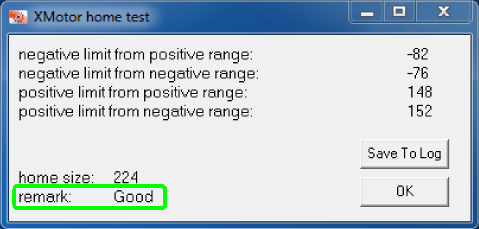 This button is
used to check the correct acting range of the sensor Home2.
This button is
used to check the correct acting range of the sensor Home2.
· If the remark
shows “bad”, the unit may work correctly, but the acting range of the sensor
“Home2” is outside the nominal limits.
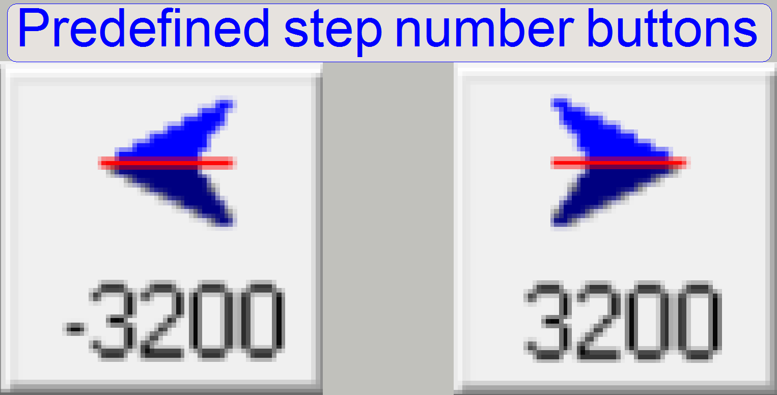 These buttons are
used to move the rotor by 1 revolution, a half revolution and by 100 steps forward
or backward respectively. If the button of the predefined number of steps is
pressed, the number of steps is done from the actual rotor position in positive
or negative direction.
These buttons are
used to move the rotor by 1 revolution, a half revolution and by 100 steps forward
or backward respectively. If the button of the predefined number of steps is
pressed, the number of steps is done from the actual rotor position in positive
or negative direction.
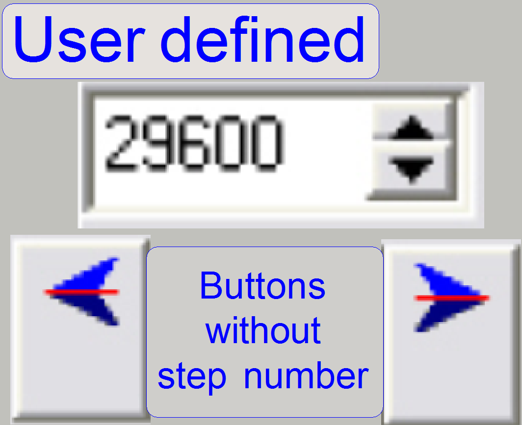 If the desired
number of steps can not be reached with the predefined step number buttons (or
the buttons should be pressed very often to reach the desired position) the
user can define in the numeric field a number of steps to go.
If the desired
number of steps can not be reached with the predefined step number buttons (or
the buttons should be pressed very often to reach the desired position) the
user can define in the numeric field a number of steps to go.
· Easily type in the
desired number of steps to go into the appropriate numerical field
· Press the
corresponding buttons without step number in positive or negative direction,
the number of steps is executed from the
actual rotor position
This possibility is often
used if the hardware limits have to be defined or checked.
Important
· This
options can easily create mechanical jamming or lost steps (as any other step
number button also) if the number of steps to go is not calculated correctly.
· The
directions forward and backward are defined in relation to the movement of the
mechanical drive; the home position is always near to the negative limit
· Creating
lost steps can be used to find the correct hardware limits!
![]() “Motor steps” and “How to define hardware limits”
“Motor steps” and “How to define hardware limits”
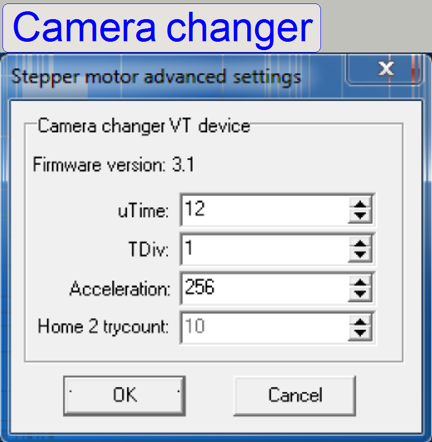
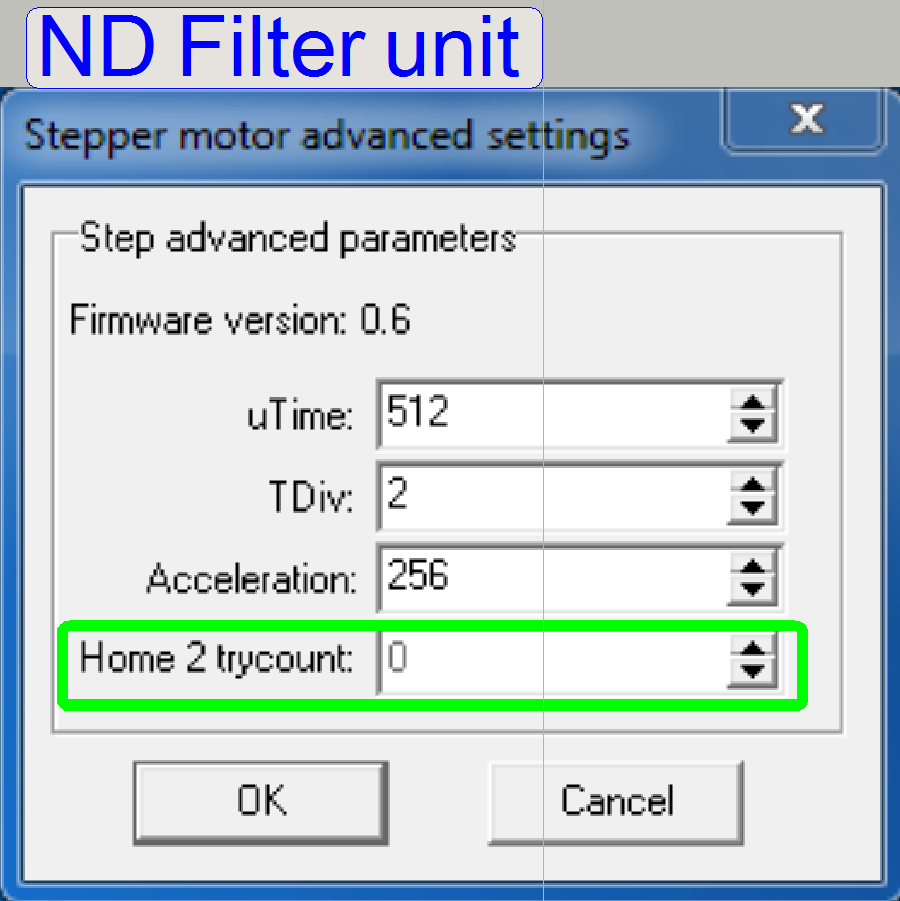
Stepper motor advanced
settings
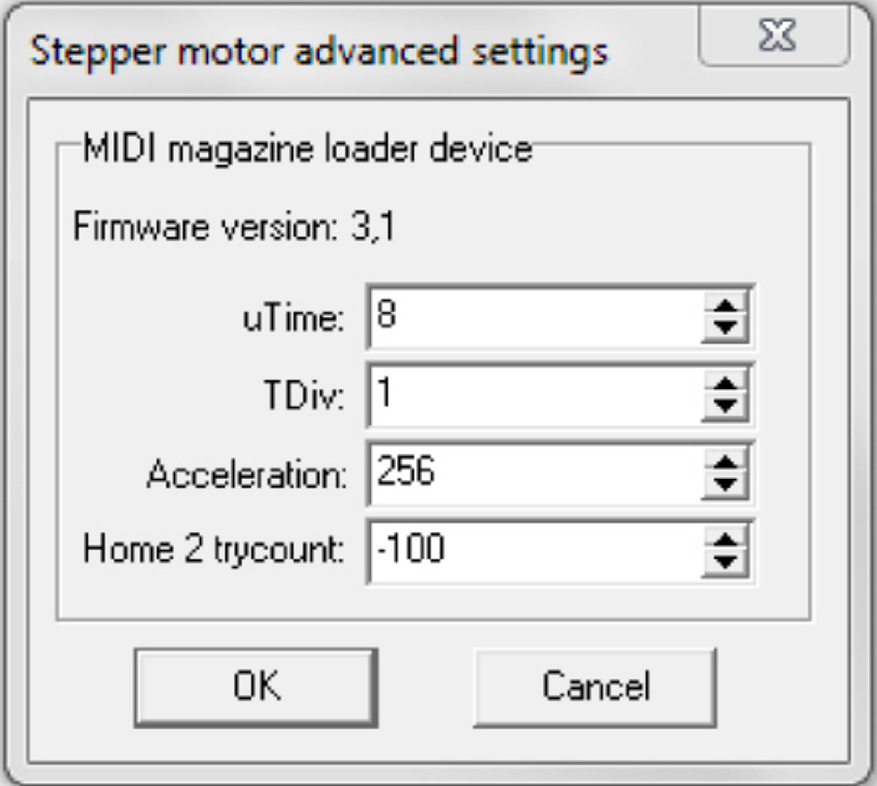 The advanced
settings for the stepper motors are very similar to each other. For useable
values of the appropriate stepper motor driven unit please refer to:
The advanced
settings for the stepper motors are very similar to each other. For useable
values of the appropriate stepper motor driven unit please refer to:
SMD: “USB and DC-controlling”, “Stepper motor”, “Step control of
stepper motors”, “Calculate the u-time”
P250: “Power and control” , “Stepper motor”, “Step control of stepper motors”, “Calculate
the u-time”
Home2 try count:
This number specifies the
maximal number of revolutions of the rotor axle to be done to reach Home2; see
also the hardware limits of the appropriate unit.
·
To activate the selected values close the dialog with OK,
press reset of the appropriate unit and then switch it active again.
 Movement range: –hardware limit < Home1,2 < +hardware
limit
Movement range: –hardware limit < Home1,2 < +hardware
limit
![]() “X-Y-stage
unit S_M_D” and “How to define
hardware limits”
“X-Y-stage
unit S_M_D” and “How to define
hardware limits”
P250
Movement range: –hardware limit < Home1,2 <
+hardware limit
![]() “P250_X-Y-stage unit” and “How to define hardware limits”,
“P250_X-Y-stage unit” and “How to define hardware limits”,
Movement range: –hardware limit < Home1,2 <
+hardware limit
![]() “X-Y-stage
unit S_M_D” and “How to define
hardware limits”
“X-Y-stage
unit S_M_D” and “How to define
hardware limits”
P250
Movement range: –hardware limit < Home1,2 <
+hardware limit
![]() “P250_X-Y-stage unit” and “How to define hardware limits”,
“P250_X-Y-stage unit” and “How to define hardware limits”,
SCAN,
Movement range: –hardware limit < Home1,2 <
+hardware limit
![]() “Focus uni S_M_D” and “How to define hardware limits”
“Focus uni S_M_D” and “How to define hardware limits”
P250
Movement range: –hardware limit < Home1,2 <
+hardware limit
![]() “P250_Focus unit with objective changer”
and “How to define hardware limits”,
“P250_Focus unit with objective changer”
and “How to define hardware limits”,
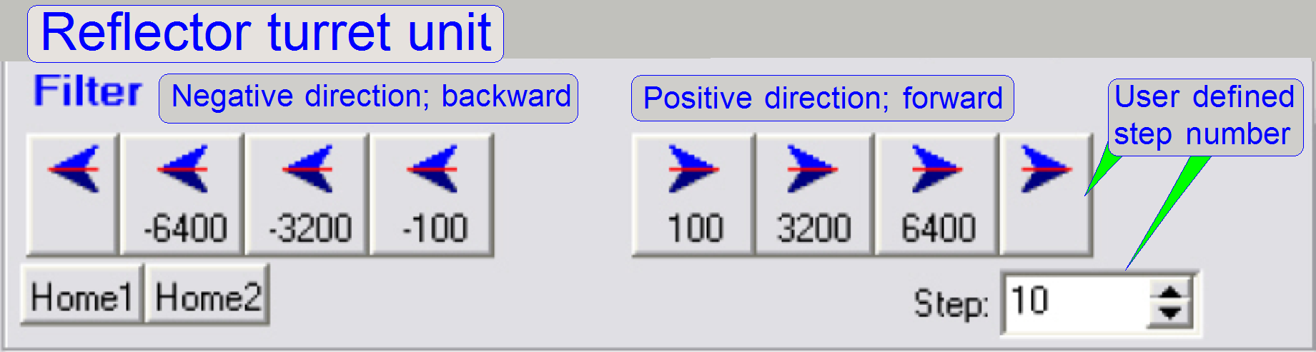 The number of steps
between two filter positions is exact 6400steps (2 revolutions of the rotor);
in the gear driven RTU; in the belt driven RTU, the number of steps between two
filter positions is exact 3200steps.
The number of steps
between two filter positions is exact 6400steps (2 revolutions of the rotor);
in the gear driven RTU; in the belt driven RTU, the number of steps between two
filter positions is exact 3200steps.
SCAN and
Movement
range: –hardware limit < Home1,2
< +hardware limit
![]() “How to define hardware limits”, “Reflector
turret unit; MIDI, SCAN”
“How to define hardware limits”, “Reflector
turret unit; MIDI, SCAN”
P250
Movement
limit: endless
![]() “How to define hardware limits”, and
“Belt driven RTU”
“How to define hardware limits”, and
“Belt driven RTU”
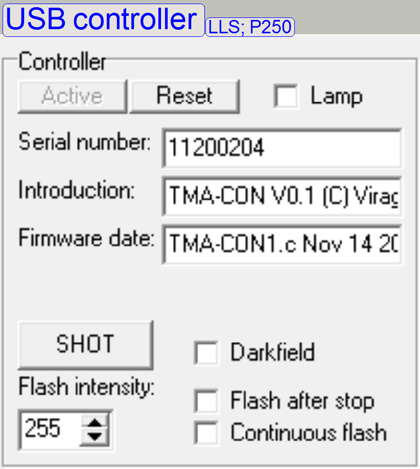
· The USB controller
must be switched active only, if one of the following options should be used.
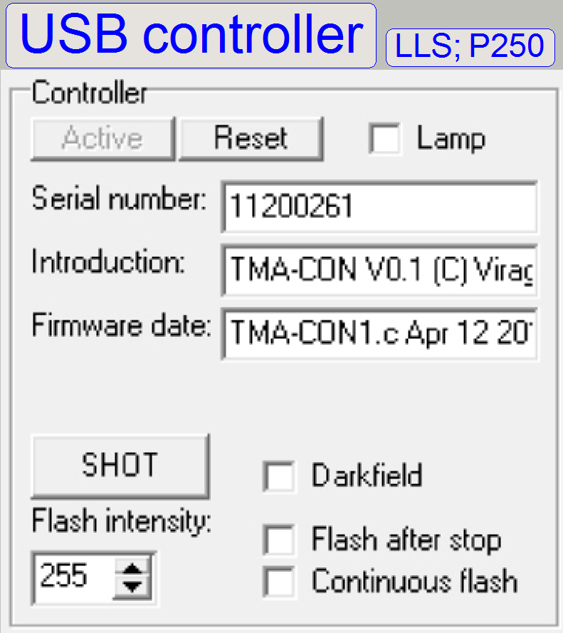
Darkfield
· Check the
darkfield illumination; switch it on or off
Continuous flash
· Generates flash
pulses.
· Check the
brightfield flash illumination for the main camera; switch it on or off
Shoot
· Generates a single
brightfield scan illumination flash pulse
Flash after stop
Flash intensity
· Defines the flash
intensity; not used
Important
Please switch all options
inactive, before SlideScanner.exe should be started.
For not shown options, please
refer to “Global unit
control” and “Tools of
DESK”
USB controller status
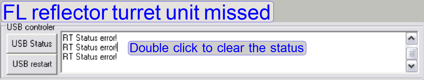
The USB controller status
field reports any error with an addressed unit.
· If the unit is
active and will not respond to the USB controller, status errors are reported.
· In the example,
the turret motor cable is not connected.
Status error reports occur, if:
·
The power supply of the scanner is switched off or not
supplied to the scanner (more units are reported).
·
The cable to the unit is not connected and the service
program starts a communication with the unit (1 unit is reported).
·
The USB controller USB cable is not connected to the
PC or the USB cable is faulty (more units are reported).
·
The USB driver of the scanner is not (or wrong)
installed (more units are reported); see also “Install the USB driver”.
·
The addressed unit has no address or the same address
as another unit (1 or two units are reported).
·
The cable to the addressed unit is faulty (1 unit is
reported).
·
The addressed unit is faulty (1 or more units are
reported).
·
The USB controller is faulty (1 or more units are
reported).
· By double click in
the status report field the status messages are cleared and actualized (if
any).
Please detect the reason for
the status error more precise.
![]()
S_M_D P250
·
“USB- and DC-controlling”,
“Power and control”, “X-Y-Z-ND control”
·
“USB
controller”, “DC controller” “USB_controller”, “DC controller”
·
“Addresses”
and “Addresses” and
·
“Setup the USB driver”. “Setup the USB driver”.
PCON
·
“Power and
control”, “X-Y-Z-motor
control”
·
“USB_controller”,
·
“Addresses”
and
·
“Setup the USB driver”.
 Please refer to “Global unit control”
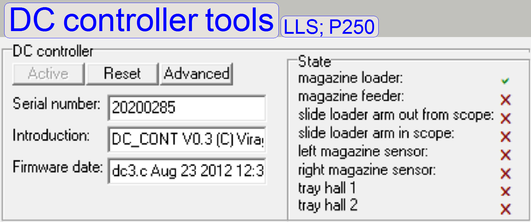
![]()
S_M_D: “USB
and DC controlling”; “DC
controllers”; “Hall_sensors”
P250: “Power and control”; “DC controller” and “Hall_sensors”
· To use any
component, connected to the DC-controller please switch it first into the
active state!
DC Control advanced
· 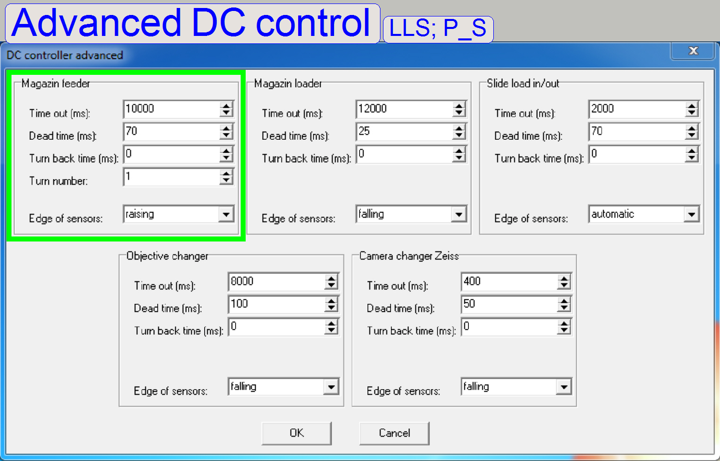 This section
defines special conditions, often time out values for DC-motor driven units and
the rising or falling edge of the appropriate sensor.
This section
defines special conditions, often time out values for DC-motor driven units and
the rising or falling edge of the appropriate sensor.
 An often used
option is the parameter “Edge of the sensor” in the SCAN and the P250.
An often used
option is the parameter “Edge of the sensor” in the SCAN and the P250.
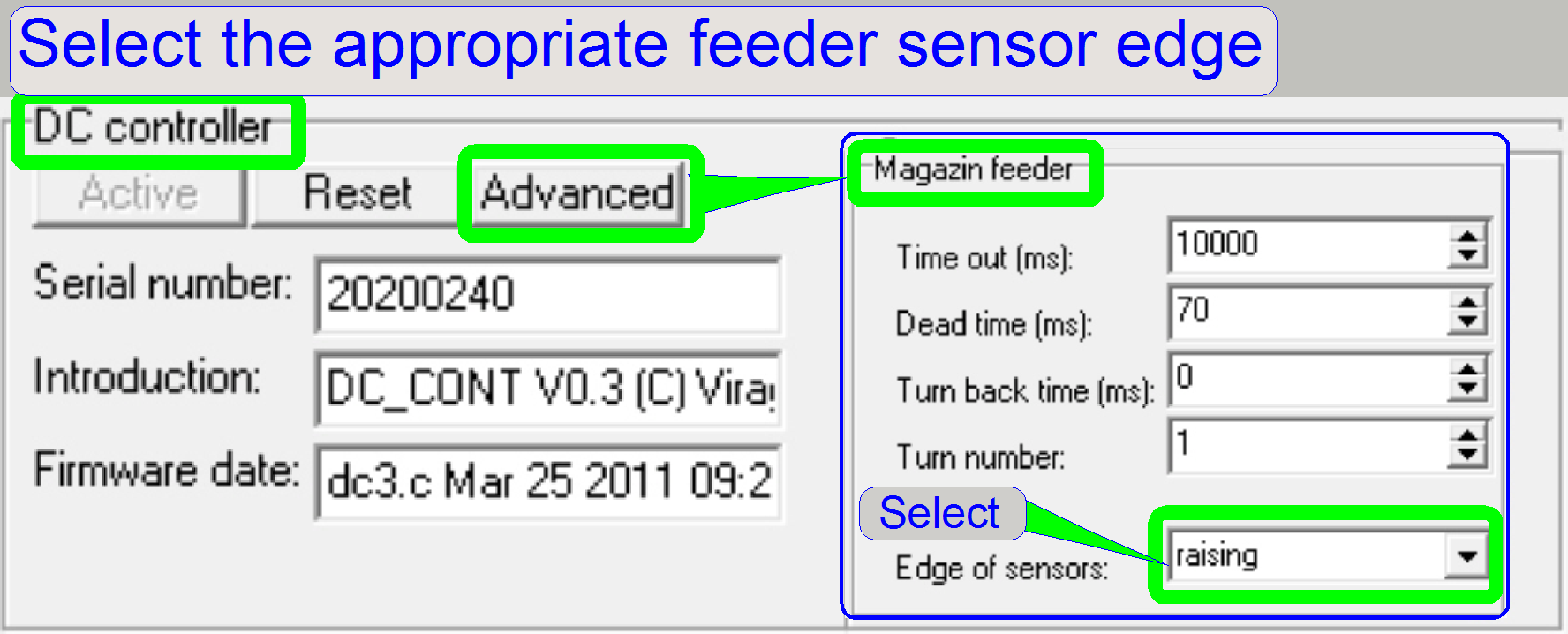
SCAN: Select
the edge of the feeder sensor as required for the appropriate scanner version,
please refer to: “Magnet disc” and “Define the feeder edge”
P250: In
the P250 always the rising edge of the feeder sensor is used, please refer to: “Set
the feeder rising edge”
Remark:
In the service program, the falling edge of the feeder is
selected by default, after start. Please check and set this option before any
magazine unit adjustments are done!
Following sections are
supported only in the P250 and the SCAN.
·  Detailed information
about the behavior of the units and their sensors can be found in the chapters:
Detailed information
about the behavior of the units and their sensors can be found in the chapters:
SCAN: “Magazine unit and slide handling”; “Magazine feeder unit”; “Magazine load unit” and “Slide loader”
P250: “Magazine unit and slide
handling”; “Magazine
feeder unit”; “Magazine
load unit” and “Slide
loader”
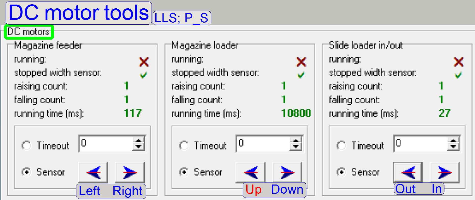
 By using the
timeout option of the appropriate unit, the motor is switched on for the time
[ms], specified in the numerical field.
By using the
timeout option of the appropriate unit, the motor is switched on for the time
[ms], specified in the numerical field.
The maximal reachable time is
10 000ms = 10s.
·
Select the option “Timeout”,
·
Type into the numerical field a value in [ms] and
·
Press the appropriate button as required.
 The Magazine
feeder unit moves the magazine
in the feeder channel by the help of the feeder DC-motor with drive. The stop
event may be:
The Magazine
feeder unit moves the magazine
in the feeder channel by the help of the feeder DC-motor with drive. The stop
event may be:
Sensor: The appropriate sensor will stop the
movement; please refer to:
SCAN: “Magazine feeder unit”; “Magazine feeder channel”
and “Magnet disc”.
P250: “Magazine
feeder unit”; “Magazine
feeder channel” and “Sensor disc”.
Time
out: The motor drive will be
stopped with a time out event.
·
In the numerical field, please type in a run time [ms]
between 1 … 10 000.
·
Start the drive by pressing the appropriate movement
button below.
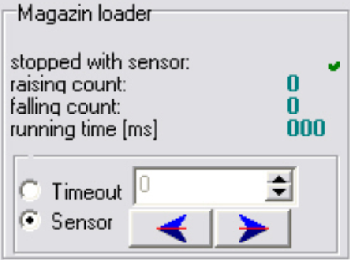 The Magazine
loader unit moves the
magazine from the input stack to the feeder channel and, in the same time, from
the feeder channel to the output stack by the help of the loader motor with
gear. The stop event may be:
The Magazine
loader unit moves the
magazine from the input stack to the feeder channel and, in the same time, from
the feeder channel to the output stack by the help of the loader motor with
gear. The stop event may be:
Sensor: The appropriate sensor will stop the
movement; please refer to:
SCAN: “Magazine load unit” and “Magazine load sensor”.
P250: “Magazine
load unit” and “Magazine
loader sensor”.
Time
out: The motor drive will be
stopped with a time out event.
·
In the numerical field, please type in a run time [ms]
between 1 … 10 000.
·
Start the drive by pressing the appropriate movement
button below.
Important
The backward direction may
create magazine stumble or magazine jamming; bee careful!
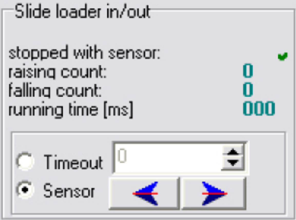
Slide loader
 The slide loader unit moves the slide into the
specimen holder or return to the position over the magazine by the help of the
slide loader moveable part. The stop event may be:
The slide loader unit moves the slide into the
specimen holder or return to the position over the magazine by the help of the
slide loader moveable part. The stop event may be:
Sensor: The appropriate sensor will stop the
movement; please refer to:
SCAN: “Slide Loader”
and “Check
the function of the slide loader sensors”.
P250: “Slide
loader” and “Check
slide loader sensors”.
Time
out: The motor drive will be
stopped with a time out event.
·
In the numerical field, please type in a run time [ms]
between 1 … 1200.
·
Start the drive by pressing the appropriate movement
button below.
Important
The value for Timeout should
not exceed 1200ms! The possible value is limited to be 10 000ms by
SSS_software!
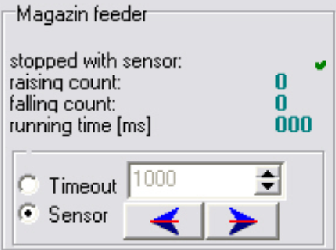
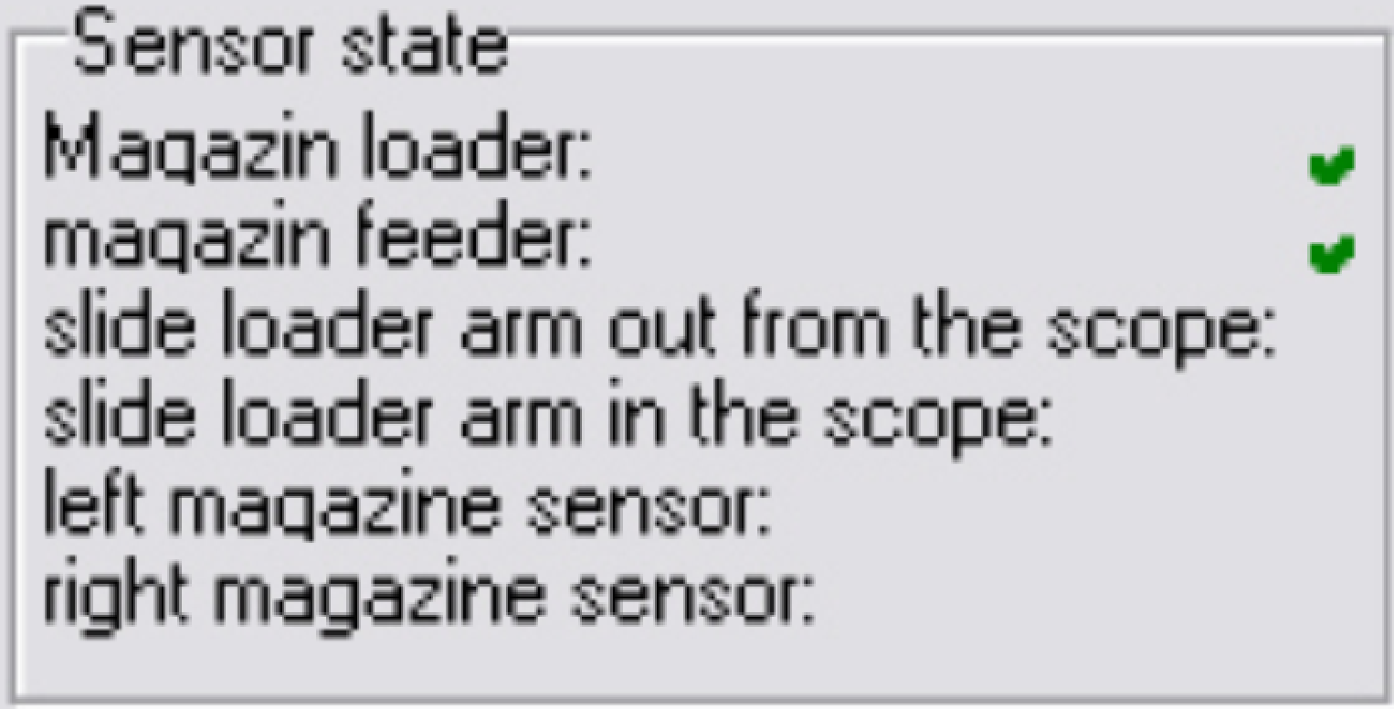 Always the actual
sensor state is shown, if the appropriate unit is in the active state.
Always the actual
sensor state is shown, if the appropriate unit is in the active state.
· The sensor state
of the “Magazine feeder” on the right is shown with the falling edge of the
sensor disc!
Please refer to the following
chapters:
SCAN: “Magazine loader
sensor”, “Magazine feeder
sensor”, “Inner and
outer slide loader sensor”, “Magazine input (left) sensor”
and “Magazine output
(right) sensor”.
P250: “Magazine
loader sensor”, “Magazine
feeder sensor”, “Inner
and outer slide loader sensor”, “Magazine
input (left) sensor” and “Magazine
output (right) sensor”.
 Please refer to “Global unit control”
See above “USB Controller”
· Please refer to “Flash light
source” and “Optics and
illumination”
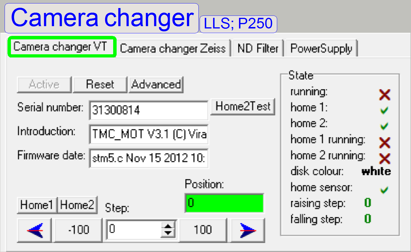
· Please refer to “Camera changer unit”
 Because the camera
changer mirror rotates exactly by 180º only, and a usual stepper motor with
control electronics is used, the Home2 try count is limited.
Because the camera
changer mirror rotates exactly by 180º only, and a usual stepper motor with
control electronics is used, the Home2 try count is limited.
Important
If the home2 can not be
reached if the Camera changer unit is assembled, please disassemble the motor
from the Camera changer housing, Set the motor to Home1,2 and reassemble the motor
to the housing again.
Procedure
to adjust the home position of the motor
1.
Disassemble
the motor from the housing
2.
Open the dialogue “Camera changer VT Advanced”
3.
Set the “Home2 try count” to 100 and close the
dialogue.
4.
Press the buttons Home1 and Home2
5.
If the rotor stops, press the buttons Home1 and Home2
again
6.
Repeat the previous 2 steps until no movement of the
rotor is expired; may be you have to press Home1,2 four times.
7.
If Home1 and Home2 are pressed and no rotation of the
rotor can be expired, the home position is found; see also the field “Position”
in the image above.
8.
Reassemble
the motor to the housing.
9.
Open the dialogue “Camera changer VT Advanced”
10. Set the “Home2 try
count” to 2 and close the dialogue.
11. Check the home
position again.
12. Mount the adjustment
tools and check
or define the
mirror rotation angle.
![]() “Adjust the Camera
changer unit” and “Adjustment
techniques”
“Adjust the Camera
changer unit” and “Adjustment
techniques”
Not used; the unit does not
exist!
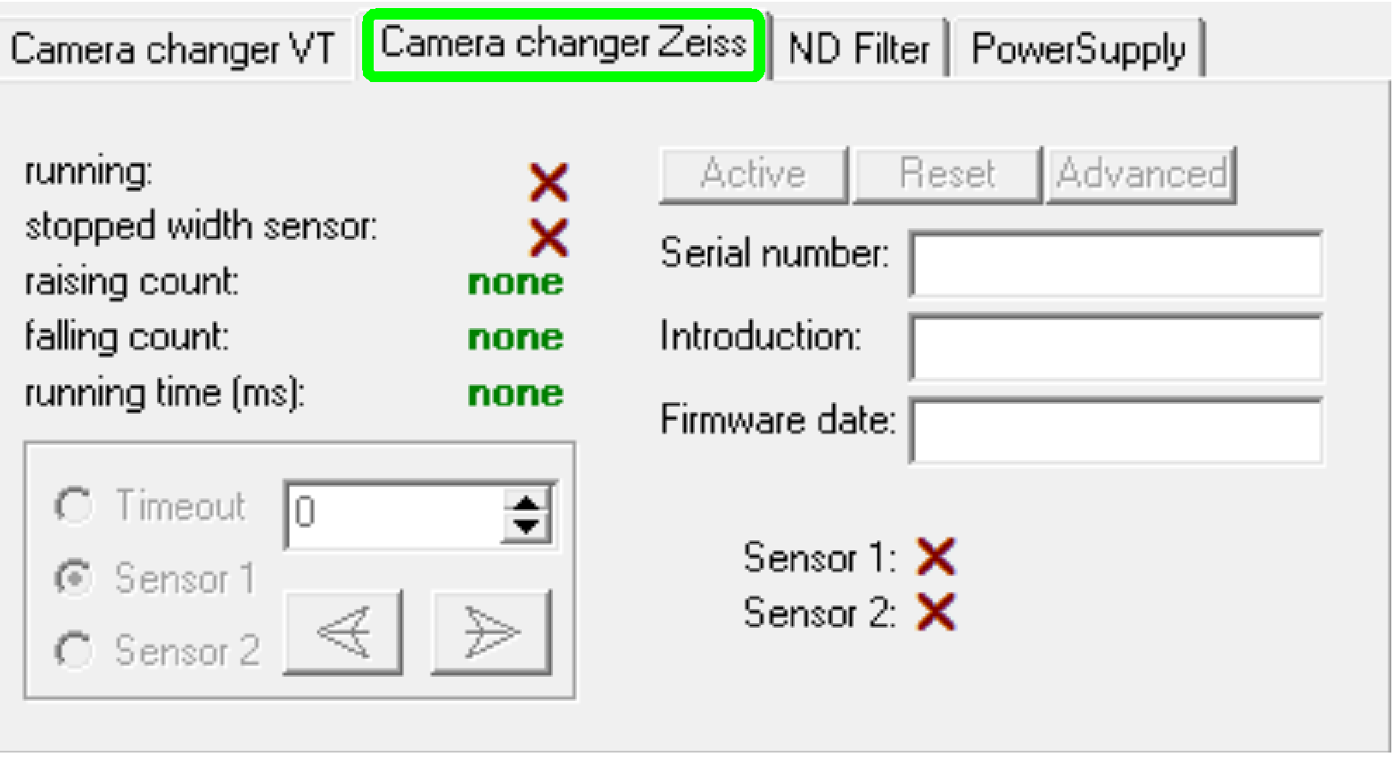
·  Please refer to “ND-Filter unit”
and “Optics and illumination”
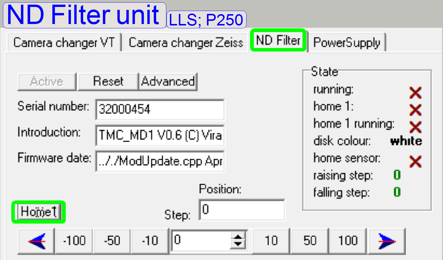
Please refer to “ND-Filter unit”
and “Optics and illumination”
 Because the movement range of the ND-filter disc
is exact 1 revolution of the stepper motor, all required positions can be
reached inside of 1 revolution and therefore, a sensor Home2 is not required.
Because the movement range of the ND-filter disc
is exact 1 revolution of the stepper motor, all required positions can be
reached inside of 1 revolution and therefore, a sensor Home2 is not required.
· Home2 try count is
always inactive; not used.
P250: “Power and control” , “Stepper motor”, “Step control of
stepper motors”, “Calculate the u-time”
To allow the power to the appropriate output,
please check the relevant checkbox.
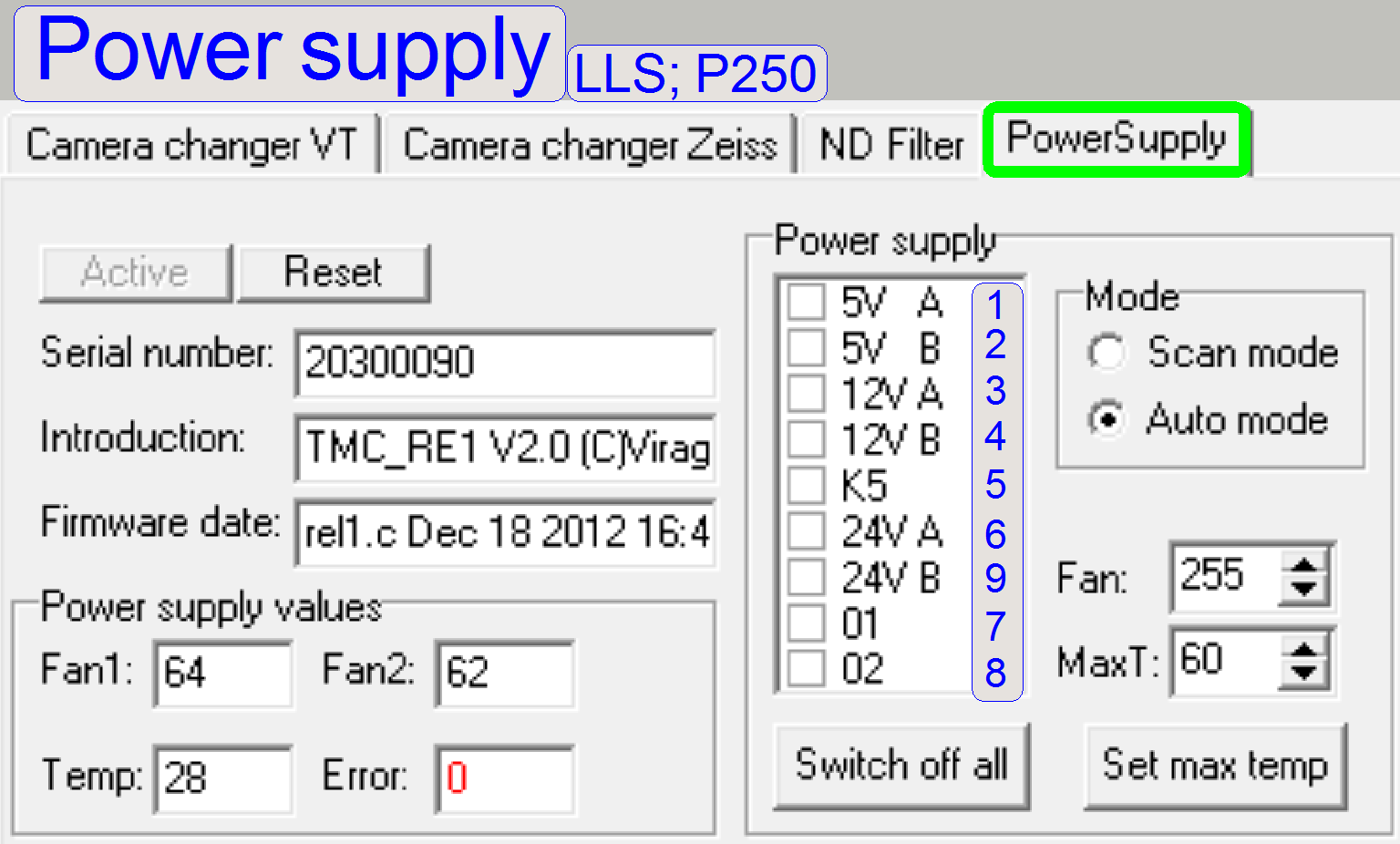
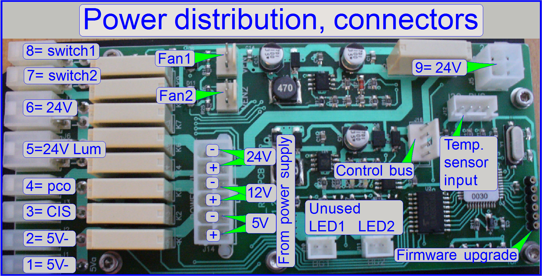
![]() “Power
and control”, “Power
distribution and switch board” and “Temperature
sensor, fan and fan control”
“Power
and control”, “Power
distribution and switch board” and “Temperature
sensor, fan and fan control”
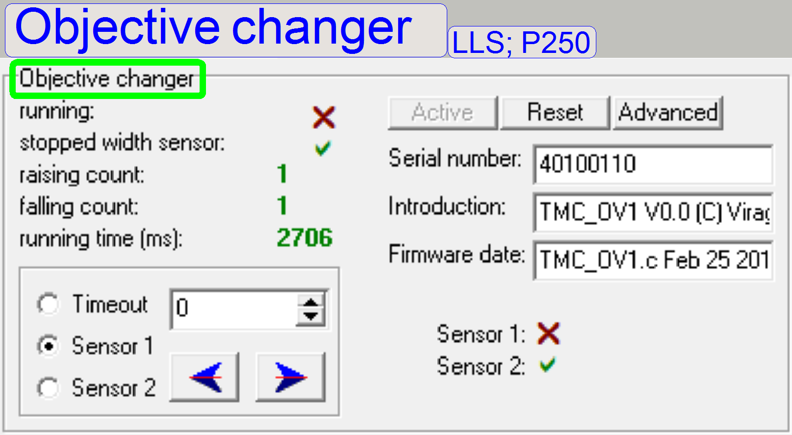
· Please refer to “Objective changer”
Tools of
Please refer to “Global unit control”
Move the tray of the
![]() “Precautions”, “Tray and slide loading”, “Tray”, “Tray conveyor unit”,
“Setup and adjustment procedures”
“Precautions”, “Tray and slide loading”, “Tray”, “Tray conveyor unit”,
“Setup and adjustment procedures”
 Move the slide
into the specimen holder or return to the tray.
Move the slide
into the specimen holder or return to the tray.
![]() “Precautions”, “Tray and slide loading”, “Principle of support plate and slide loader spreading”, “Slide loader and support
plate mechanics”, “Setup and
adjustment procedures”
“Precautions”, “Tray and slide loading”, “Principle of support plate and slide loader spreading”, “Slide loader and support
plate mechanics”, “Setup and
adjustment procedures”
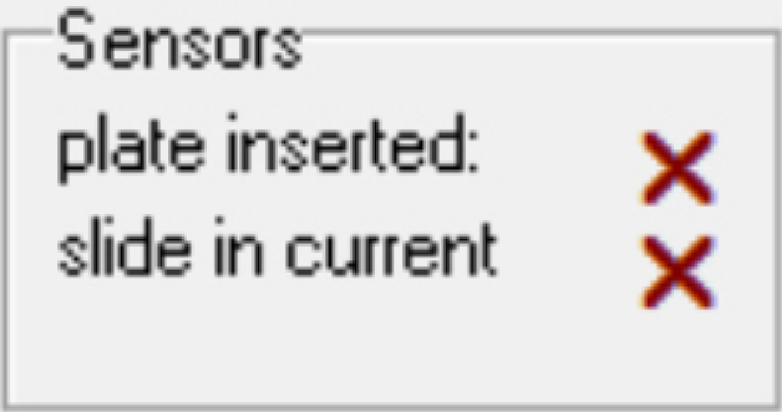 Tray not inserted,
therefore, a slide can also not be detected; correct statement
Tray not inserted,
therefore, a slide can also not be detected; correct statement
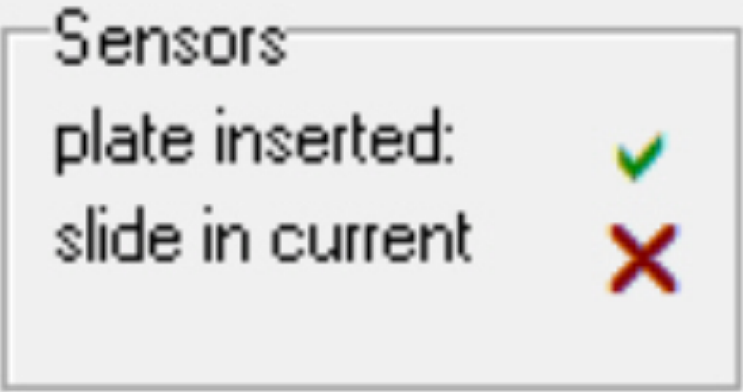
If a tray is inserted and a
slide is not present in the tray position1
· Sensor position of
the tray is adjusted wrong or the mounting bolt is not tightened
· DC-controller not
connected to the USB-controller; check the connection of the cable “DCX-
· Contact fault or
the cables are connected to the opposite (wrong) sensor; check the cables and
positions
· DC-controller
defective or wrong connection of the sensor cables inside the DC-controller.
· Permanent magnet is
missed in the tray.
![]() “Tray sensor”, “Slide sensor”, “DC-controller”
“Tray sensor”, “Slide sensor”, “DC-controller”
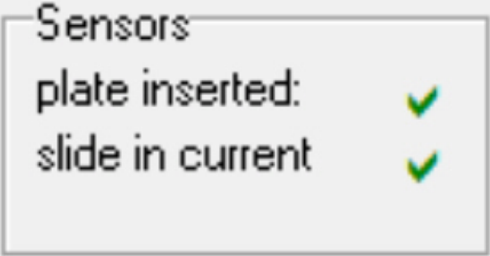
If a tray is inserted and a
slide is present in the tray position1
· Tray and slide
recognized; correct statement
If the tray is not inserted
· None of the
sensors connected
· Contact fault;
check the cables
· DC-controller defective
or no connection of the sensor cables inside the DC-controller.
![]() “Tray sensor”, “Slide sensor”, “DC-controller”
“Tray sensor”, “Slide sensor”, “DC-controller”
If the tray is inserted and
no slide in the tray position 1
· Incorrect sensor
connection; exchange the cable connection of the cables HAG-1 and HAG-2 on the
sensor side or in the DC-controller.
![]() “Tray sensor”, “Slide sensor”, “DC-controller”
“Tray sensor”, “Slide sensor”, “DC-controller”
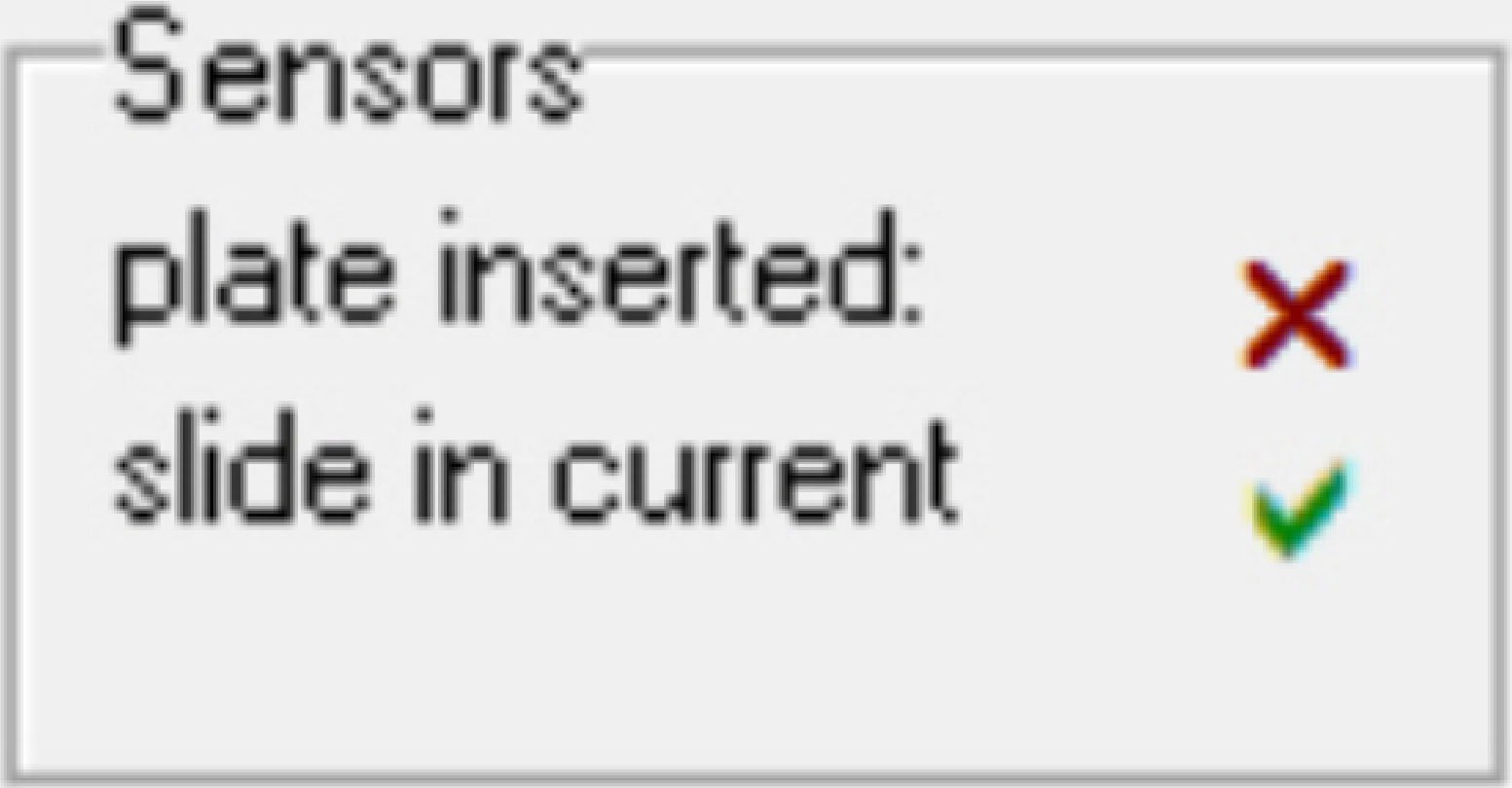
 The shown sensor
state is correct, if a tray is inserted and a slide is not present in the first
slide bay.
The shown sensor
state is correct, if a tray is inserted and a slide is not present in the first
slide bay.
If a slide is present in the
position 1, probably errors may be:
· The slide is too
short; check the functionality of the sensor.
· Slide sensor not
connected or contact faulty cable.
· Slide sensor is
connected to a wrong connector position inside the DC-controller
· Slide sensor not
adjusted well, even if the shortest allowed slide is inserted.
· DC-controller
defective.
· Permanent magnet
is missed in the slide sensor.
![]() “Tray
sensor”, “Slide
sensor”, “Adjust tray sensor position”, “Adjust slide sensor position”, “DC-controller”
“Tray
sensor”, “Slide
sensor”, “Adjust tray sensor position”, “Adjust slide sensor position”, “DC-controller”
 If the DESK is recognized all the units not used
in the DESK are disabled or not shown.
If the DESK is recognized all the units not used
in the DESK are disabled or not shown.
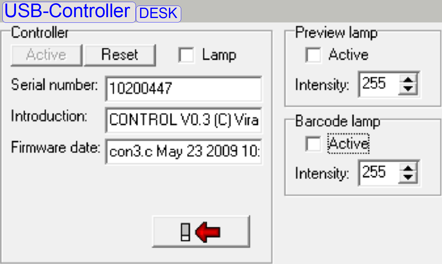
Lamp:
Check the working of the main
camera’s brightfield illumination,
The “Background Intensity” is used to
test or check the Preview
illumination.
·
Check the checkbox “Active” and
·
Type in a numerical value between 1 and
![]() “USB- and DC-controlling” and “Preview illumination”.
“USB- and DC-controlling” and “Preview illumination”.
 The “Barcode Lamp Intensity” is used to
test or check the barcode
illumination.
The “Barcode Lamp Intensity” is used to
test or check the barcode
illumination.
·
Check the checkbox “Active” and
·
Type in a numerical value between 1 and
![]() “USB- and DC-controlling” and “Barcode illumination”.
“USB- and DC-controlling” and “Barcode illumination”.
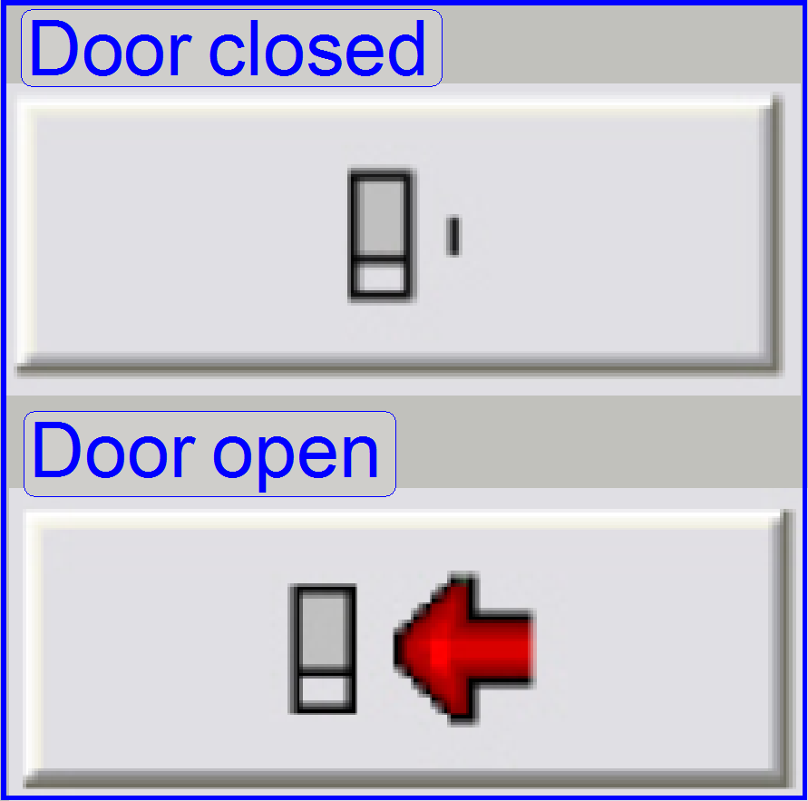
The state of the door (sensor) is
shown with these two symbols on the right.
![]() “USB- and DC-controlling” and “Hall sensors”.
“USB- and DC-controlling” and “Hall sensors”.
“Housing and
construction” and “Adjust
the door sensor position”
· Possible
only since the software version 1.18
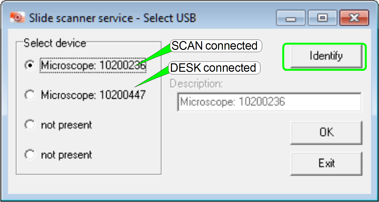 After the Low
Level Service part (LLS) is started and there are more USB controllers
connected, the dialogue “Select USB” is opened.
After the Low
Level Service part (LLS) is started and there are more USB controllers
connected, the dialogue “Select USB” is opened.
If an USB connection between
USB controller and the computer exists, the serial number of the found USB
controller is shown and used to identify the connected scanner or units.
By pressing “OK” the
activated LLS part will be opened for the selected controller.
If two USB controllers are
connected, the corresponding ini-file of the second unit should be located in a
different folder; e.g. “UnitTest”
Example:
· C:\ProgramData\3DHISTECH\SlideScanner\MicroscopeConfiguration.ini First unit or scanner
· C:\ProgramData\3DHISTECH\SlideScanner\UnitTest\MicroscopeConfiguration.ini Second unit
Software version 1.18; Pannoramic SCAN with objective changer
[Microscope]
MicroscopeType=3DMic11
LoaderType=SL_6Mag_25Slide_NoSensor_Vertical_2
CameraChangerType=CC_None; VT_Type Camera changer not present; but a manual camera changer may existReflectorTurretType=RT_3DH_10Pos_Gears; Gear driven RTU presentBrightfieldLightSourceType=BLS_Halogen_5W; Brightfield illumination type; in opposite to the P250ObjectiveChangerType=OC_2Pos; Objective changer unit as used in the P250; focus unit is the same as described in the S_M_D focus unit. ObjectGuideXYZType=OGXYZ_1.0mm; the nominal slide thickness is 1.0mm; see also: SCAN; slide dimensionsFlashUnitType=NoFlashUnit; Flash light illumination not present; NDFilterType=ND_NonePreviewLightType=PreviewLightUnitType_Type3; Camera Vrmagic and tamron objective; see also: Preview_S_M_DPowerSwitchBoardType=PowerSwitchBoard_None
[Focus]NoFocusPinOnTheObjectHolderX=29600; X-stage position during objective change procedureNoFocusPinOnTheObjectHolderY=18000; Y-stage position during objective change procedure
[ObjectiveChanger]ObjectiveChangerTimeout=7000; Time out value during a half revolution of the objective disc movement
Software version 1.18; MicroscopeConfiguration.ini
(
[Microscope]
MicroscopeType=3DMic10; The
difference to the SCAN with objective changer
LoaderType=SL_1Mag_12Slide_Sensor_Horizontal
CameraChangerType=CC_None
ReflectorTurretType=RT_3DH_10Pos_Gears
BrightfieldLightSourceType=BLS_Halogen_5W
ObjectiveChangerType=OC_2Pos
ObjectGuideXYZType=OGXYZ_1.0mm
FlashUnitType=NoFlashUnit
NDFilterType=ND_None
PreviewLightType=PreviewLightUnitType_Type3
PowerSwitchBoardType=PowerSwitchBoard_None
[Focus]
NoFocusPinOnTheObjectHolderX=26000; X-stage position during objective change procedure
NoFocusPinOnTheObjectHolderY=18000; Y-stage position during objective change procedure
[ObjectiveChanger]
ObjectiveChangerTimeout=7000