Reflector turret unit; P250
Belt driven
For
technicians and partly for sales managers!
These instructions describe the procedures to install
and adjust the Belt driven Reflector Turret Unit (RTUB) for
the scanner Pannoramic 250. To help
to resolve problems with the turret unit or problems with fluorescent scanning
a functional overview, a hardware description of the used components and
adjustment procedures are added.
The following description is based on the Software
version 1.15 and the slide scanner “Pannoramic

Precautions: Never look directly into the beam of the fluorescent light
source! The lamp emits also ultraviolet light with very high intensity. To
prevent your eyes from harm (damage) use always sun glasses with a high filter
factor of UV light if the fluorescent light source is switched on and you are
adjusting the beam even if the cover of the turret unit is removed. For further
precautions please, refer to the manual for the fluorescent light source you
are using!
For safety
regulations regarding human health and scanner functionality please refer to: Precautions
Contents
Configure the belt driven
reflector turret unit
Functional overview of the
reflector turret unit
Construction of
the fluorescent exciting and image path
Mechanical components and construction
·
Stepper motor and the belt wheel
·
Diaphragm
position adjustment tools
·
Remove or mount the FL
reflector turret unit
Optical components
·
Light source
adapter and mounting
·
EPI-fluorescent
illumination unit
·
Mirror
Adjustment techniques / checks
·
Tools, used for the
adjustments
·
Check and adjust the
tightness of the belt
·
Adjust the external
sensor position
·
Find the first
filter position
·
Adjust the aperture position
·
Adjust the aperture size
·
Adjust the Luminous field position
·
Adjust the luminous field size
·
Check the
correctness of the filter fixing in the filter positions
Adjustment procedure
The reflector turret unit is a component added to the Pannoramic P250 scanner to give the
possibility for fluorescent exciting and scanning of tissues; the component is
not used during the brightfield scan process. For fluorescent scanning of
tissues, light wave length filters are used in many variations; the filters are
assembled into a filter block. The filter wheel in the turret unit has ten
positions, so it can contain up to 9 filter blocks for the fluorescent scan
procedure of stained tissues; in the tenth position of the filter wheel, the
image cover tube have to be inserted. The
inserted filters (positions) can be selected by software during the
manual fluorescent scan procedure; the assigned filter(s) will be selected
automatically during the automatic scan procedure.
The exchange of
the entire turret unit is possible
- If the stepper
motor or its electronics
of the turret unit is faulty.
- If the shape of any part is deformed or a part is broken.
- If the turret unit has any fault and you are unable to fix it.

·
Service program for Pannoramic scanners (SlideScanner
Service.exe) with actual license file
·
Pannoramic Scan and Pannoramic Viewer
software (SlideScanner.exe,
SlideViewer.exe)
with dongle or actual license file
·
1.5, 2.5, 3 and 5 mm hex key wrenches,
·
Hardware
and construction knowledge of the Pannoramic 250.
·
Deeper knowledge of handling the Pannoramic
Scan and Pannoramic
VIEWER software
Configure
the belt driven reflector turret unit
Since the software version 1.15 the units of the scanner are configured
in the file “MicroscopeConfiguration.ini”, section [Microscope].
[Microscope]
SerialNumber=xxxxx
MicroscopeType=3DMic9
ScanCameraType=
PreviewCameraType=CVrmc_m8_pPro
BarcodeReaderType=PreviewCamera
LoaderType=SL_9Mag_25Slide_Sensor_Vertical
CameraChangerType=CC_3DH_2Pos
ReflectorTurretType=RT_3DH_10Pos_Belt
BrightfieldLightSourceType=FlashLight2010
ObjectiveChangerType=OC_2Pos
ObjectGuideXYZType=OGXYZ_FLASH3
FlashUnitType=FlashUnit_Type2
NDFilterType=NDType2
PreviewLightType=PreviewLightUnitType_Type2
PowerSwitchBoardType=PowerSwitchBoard_Type1
The actual version of the belt driven reflector turret unit in the
scanner Pannoramic 250 is:
ReflectorTurretType=RT_3DH_10Pos_Belt; if the turret unit is
implemented.
ReflectorTurretType=RT_None; if the turret
unit is not implemented; brightfield
scan only
If modifications are done in the file
“MicroscopeConfiguration.ini”, the scan software “SlideScanner.exe” has to be
started again; only so the modifications take effect (this is true for some
parts of the service program also).
![]() Parameter options of the
section
Parameter options of the
section
Functional overview of the reflector turret unit
The turret unit allows the exciting of the fluorescent
stained tissue via the relevant filter block and the objective.
The filter wheel of the turret unit has 10 positions and
may so contain up to 9 filter blocks; in the 10th position the image cover tube
is inserted.
· The
appropriate filter is selected via software buttons (or automatically) before
the FL scan procedure starts.
· If
single band filters are used, the actual filter block is often changed to a
filter block with another wave length.
· By
using multi band filters, the movement of the filter wheel is not required during
the scan procedure and so, the scan time of the tissue is drastically reduced.
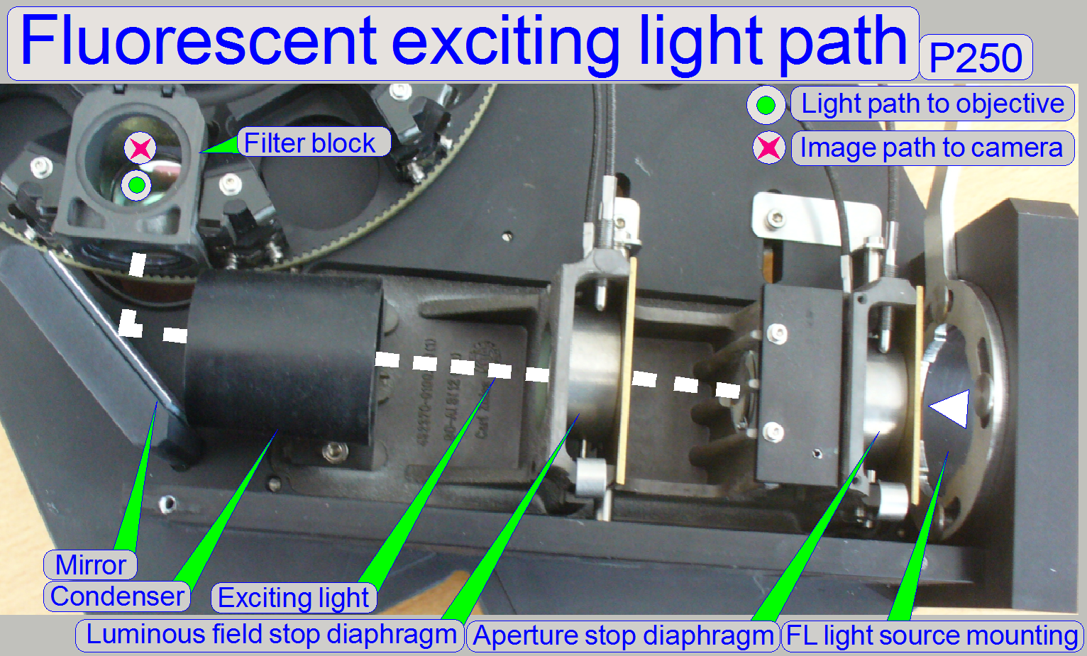
Construction of
the fluorescent exciting and
image path
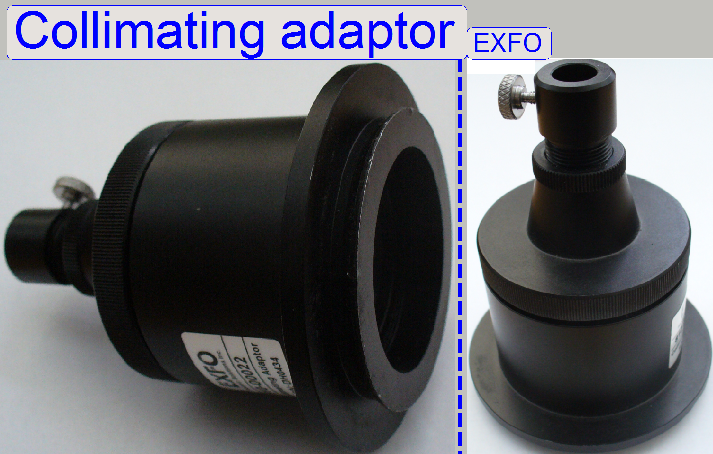
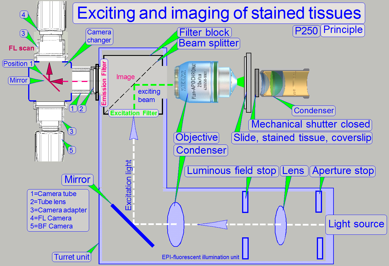 The
fluorescent light source is connected to the turret unit via the „Fluorescent
light source adapter mounting”; the adapter itself is used to interfacing the
traditional light source like the „X-Cite® Series 120” or the “Lumencor®”
exciting light source. The different interfaces are realized via separate
adapters. The tissue
is stained and prepared to fluoresce, if it is excited with a high intensity
light. The emitted light beam of the light source is prepared by the “Aperture
stop diaphragm” and the “Luminous field stop diaphragm”.
The
fluorescent light source is connected to the turret unit via the „Fluorescent
light source adapter mounting”; the adapter itself is used to interfacing the
traditional light source like the „X-Cite® Series 120” or the “Lumencor®”
exciting light source. The different interfaces are realized via separate
adapters. The tissue
is stained and prepared to fluoresce, if it is excited with a high intensity
light. The emitted light beam of the light source is prepared by the “Aperture
stop diaphragm” and the “Luminous field stop diaphragm”.
The mirror reflects the light beam to the excitation
filter of the “Filter block”.
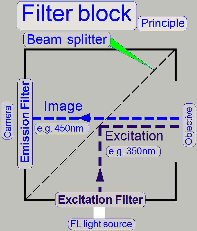
In the filter block the excitation filter, the beam
splitter and the emission filter are combined for a special excitation and the
relevant emission wave length.
The appropriate wave length of the excitation light
beam passes thru the excitation filter and will be reflected to the objective
by the help of the beam splitter.
The optics in the objective is used to illuminate the
tissue and excites the used stain of the field of view.
The stain of the tissue fluoresces and the emitted light
rays (in a higher wave length then the excitation wave length; with less
brightness) are collected by the objective; the image passes thru the beam
splitter, the emission filter, the tube lens and the camera changer to the CCD
of the scan camera.
The wave lengths of the components (the excitation
light wave length, the characteristics of the filter block and the used stain
of the tissue) are combined for a specified light wave length; this must be met
by all used components, otherwise the quality of the scanned tissue is reduced
or even bad.
![]() “Optical path and
Field Of View”
“Optical path and
Field Of View”
Physical solution
of the exciting path
 Traditionally,
the fluorescent light beam may contain all the wavelengths from ultra violet
(from about 350nm) thru the visible light (about 400nm to 720nm) until the
infra red spectrum (over 720nm to 1000nm). The relevant wavelength to excite
the stain (fluorophore) of the tissue is filtered and passes thru the
excitation filter; all other wavelengths will be reflected. In other words, the
characteristic of the excitation filter defines the light wave length to excite
the stained tissue.
Traditionally,
the fluorescent light beam may contain all the wavelengths from ultra violet
(from about 350nm) thru the visible light (about 400nm to 720nm) until the
infra red spectrum (over 720nm to 1000nm). The relevant wavelength to excite
the stain (fluorophore) of the tissue is filtered and passes thru the
excitation filter; all other wavelengths will be reflected. In other words, the
characteristic of the excitation filter defines the light wave length to excite
the stained tissue.
The filtered wavelength will be reflected to the
objective by the beam splitter and so the fluorophore in the field of view of
the tissue will be illuminated (excited).
Important
The characteristic of the excitation filter and the
beam splitter must meet the exciting wavelength of the fluorophore!
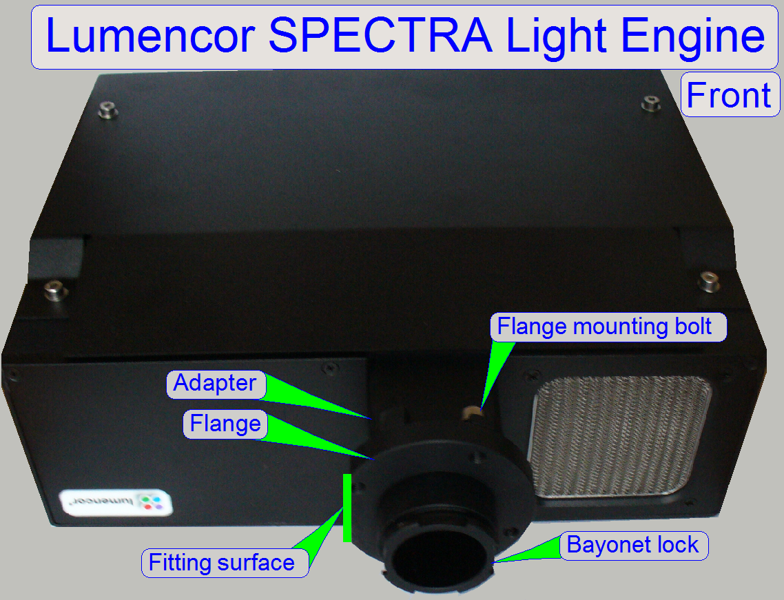
In newer exciting light sources like the Lumencor® Spectra,
the exciting light will be generated by powerful light modules which produce
the exciting light wavelength directly. By switching the modules and using
multi band filters, combined for more wavelengths in the same filter block
(e.g. Quad Band Filters),
the movement of the filter wheel can be reduced to a minimum and so the
fluorescent scan procedure is less time consuming.
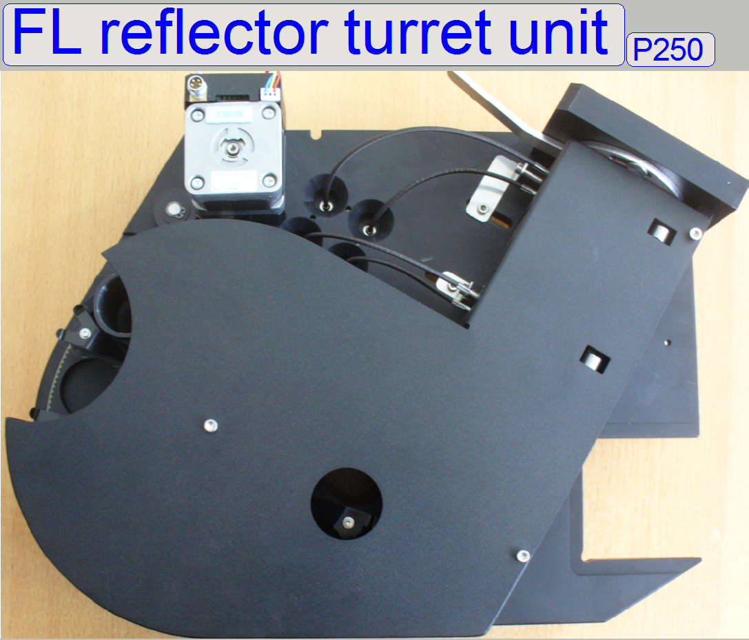
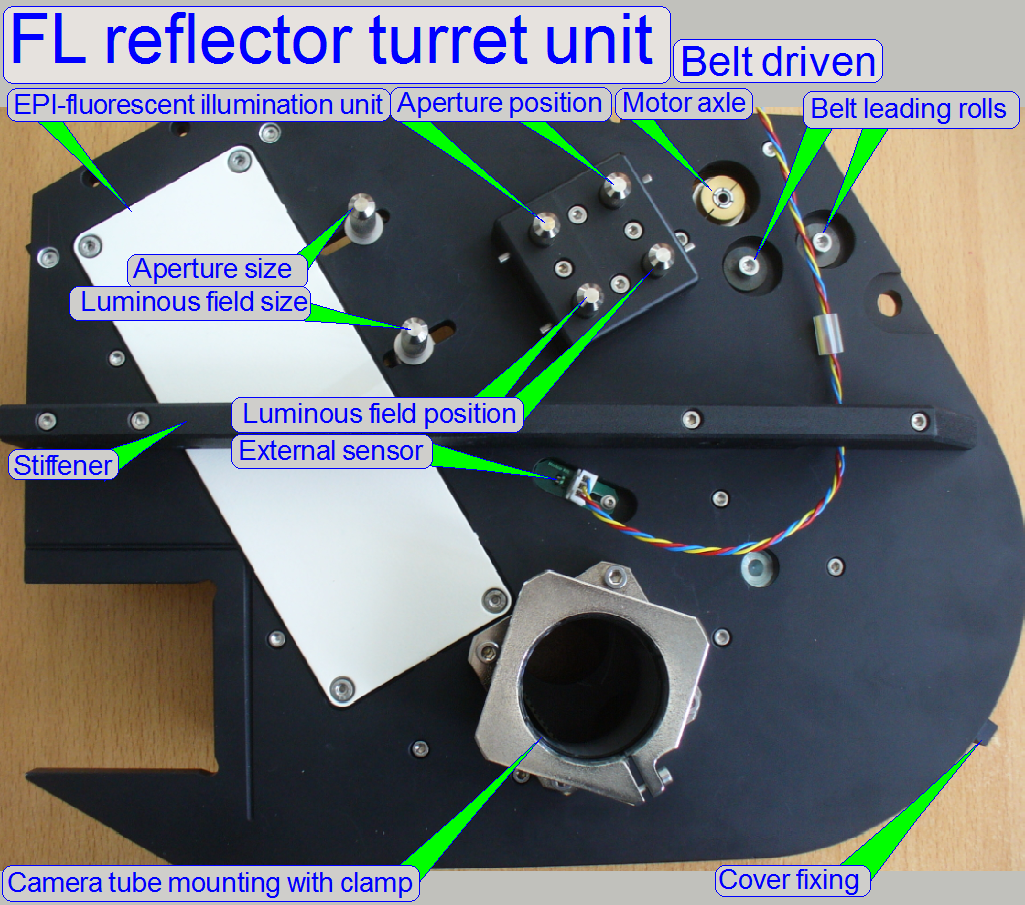
Construction of the belt driven FL reflector turret
unit
1.
Exciting light
source adapter mounting
2.
Exciting light
source adapter fixing latch
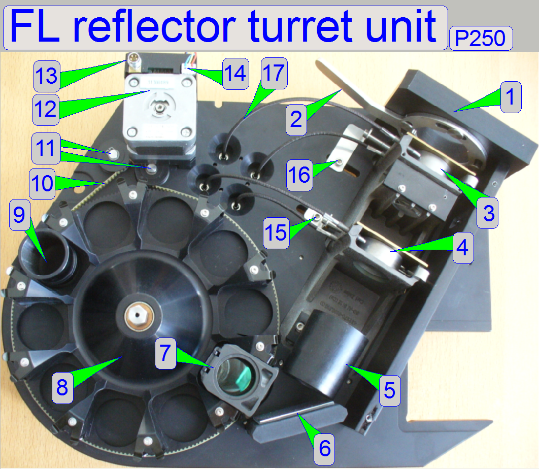
4.
Luminous
field stop diaphragm
5.
Condenser
6.
Mirror
7.
Filter block
8.
Filter wheel
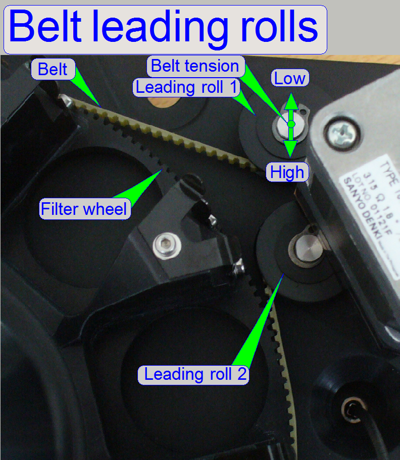
10. Belt
11. Belt leading rolls and belt
tightness
12. Turret motor
13. Power and control connector
14. External Home sensor connector
15. Luminous field size
adjustment
17. Flexible
shaft for the
position adjustment bolt
in
relation to the gear driven FL reflector turret unit consist of:
- The filter wheel is belt driven, so the cogs of the belt driven filter
wheel are different in shape in relation to the gear driven version; the
drive gear and its mounting were removed.
- The distance to the previous / next filter position is now 3200
motor steps (the distance between 2 filter positions).
- The tightness and the position of the belt are defined by the
implemented belt leading rolls.
- The limiter is removed, so the filter wheel may rotate endless in
any direction.
- To find the start position of the filter wheel an external Home
sensor is implemented; so the filter wheel can be moved now from filter
position to filter position without hardware limitations.
·
The solution of the light input connection
was modified; so the Lumencor®
or conventional fluorescent light sources can be connected via separate,
special adapters.
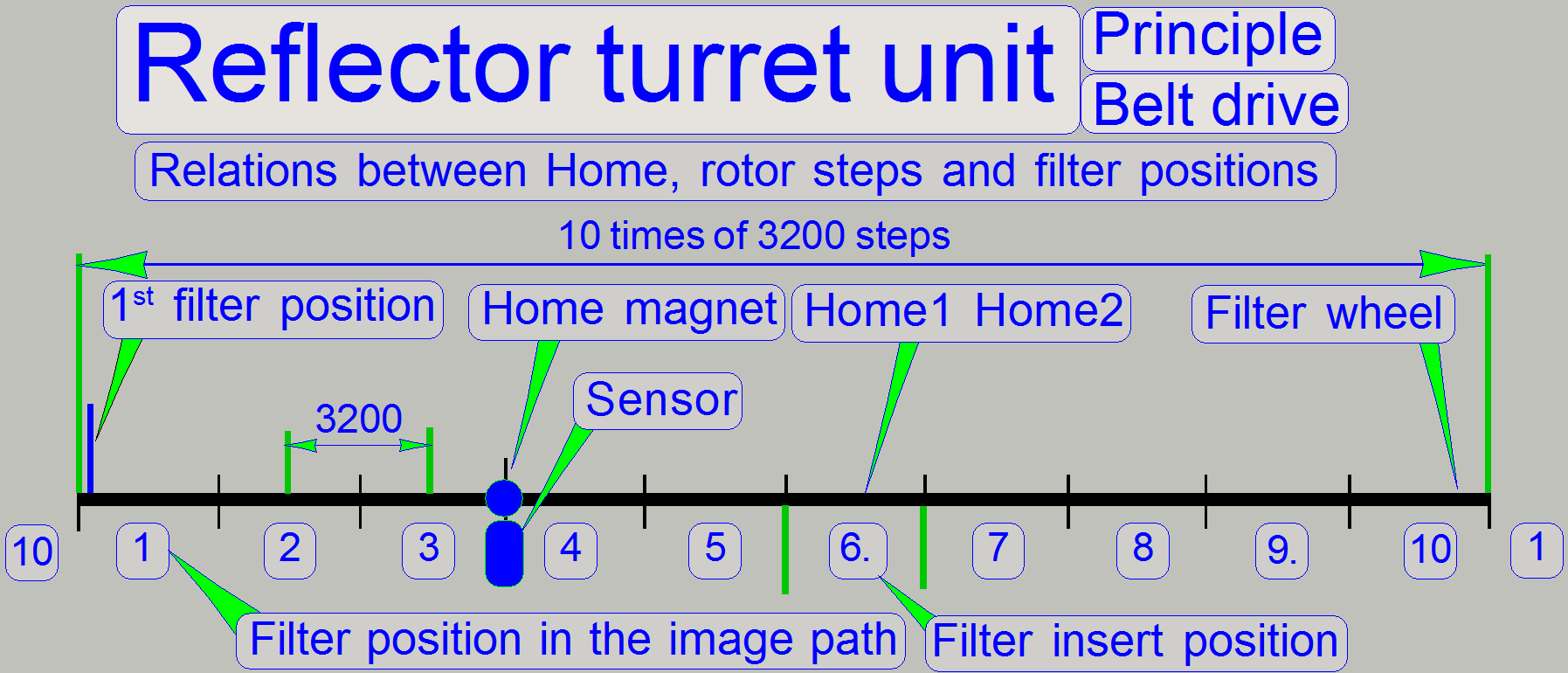 If the
filter wheel is in the Home1,2 position (the Home1 sensor in the stepper motor
is active and the permanent magnet stays over the external sensor) the filter
in the position 6 of the filter wheel can be inserted or exchanged and the
filter in the position 1 of the filter wheel stays in the light and image path.
If the
filter wheel is in the Home1,2 position (the Home1 sensor in the stepper motor
is active and the permanent magnet stays over the external sensor) the filter
in the position 6 of the filter wheel can be inserted or exchanged and the
filter in the position 1 of the filter wheel stays in the light and image path.
The first filter position defines the exact filter
block position in the exciting / image path.
Because the external home sensor position is not
always exactly on the same position (the position of the belt wheel on the
motor axle in relation to Home1 and the position of the permanent magnet in
relation to the external sensor), the value of the “first filter position”
defines a deviation in motor steps, in relation to the found Home1,2 position.
The “first filter position” is defined in the file
“MicroscopeConfiguration.ini” section [ReflectorTurret] with the parameter
value of “StartingMotorPosition=”.
The deviation from the Home1,2 position is often +-
some 10 steps only.
- See also “Adjust the
home position”, “External
sensor” and “Find the first
filter position”.
Mechanical
components and construction
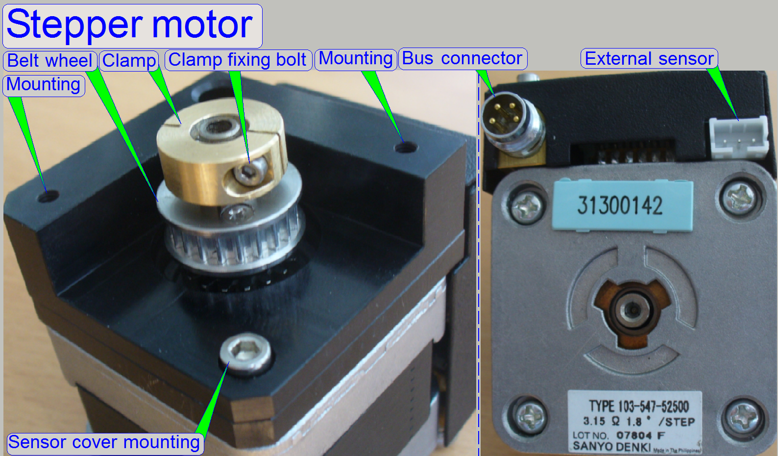 The stepper motor
is used to rotate the filter wheel of the turret unit and so, any inserted
filter (or filter position) can be selected via software commands at the
appropriate moment.
The stepper motor
is used to rotate the filter wheel of the turret unit and so, any inserted
filter (or filter position) can be selected via software commands at the
appropriate moment.
- The stepper motor of the belt driven reflector turret unit gets its
commands via the bus cable
FCJ-1 (prolonged from the objective changer unit).
- The address of the
motor electronics is 06.
- The
external sensor of the filter wheel is connected to the electronics of
the turret stepper motor and replaces the motor internal Home2 sensor.
- The stepper motor is mounted to the turret plate via the threads
“Mounting”.
Sensor cover and
motor mounting
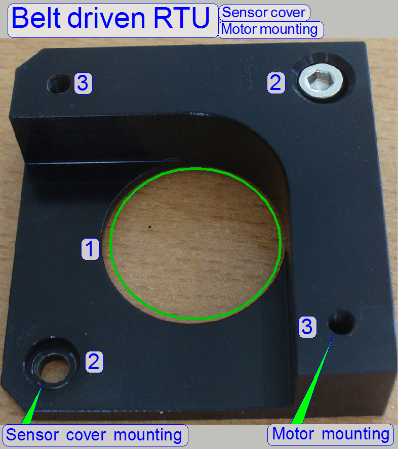 The
sensor cover and motor mounting connects the stepper motor to the turret plate.
The
sensor cover and motor mounting connects the stepper motor to the turret plate.
1 = Motor axle drilling
This drilling is always situated in the center of the
mounting; it differs in diameter according to the requirements of the connected
peripheral.
2 = Sensor cover mounting
Two bolts in diagonal position fixing the sensor cover
to the motor.
3 = Motor mounting to the mechanical drive
The motor mounting solution differs according to the
possibilities or requirements, offered by the mechanical drive to be connected.
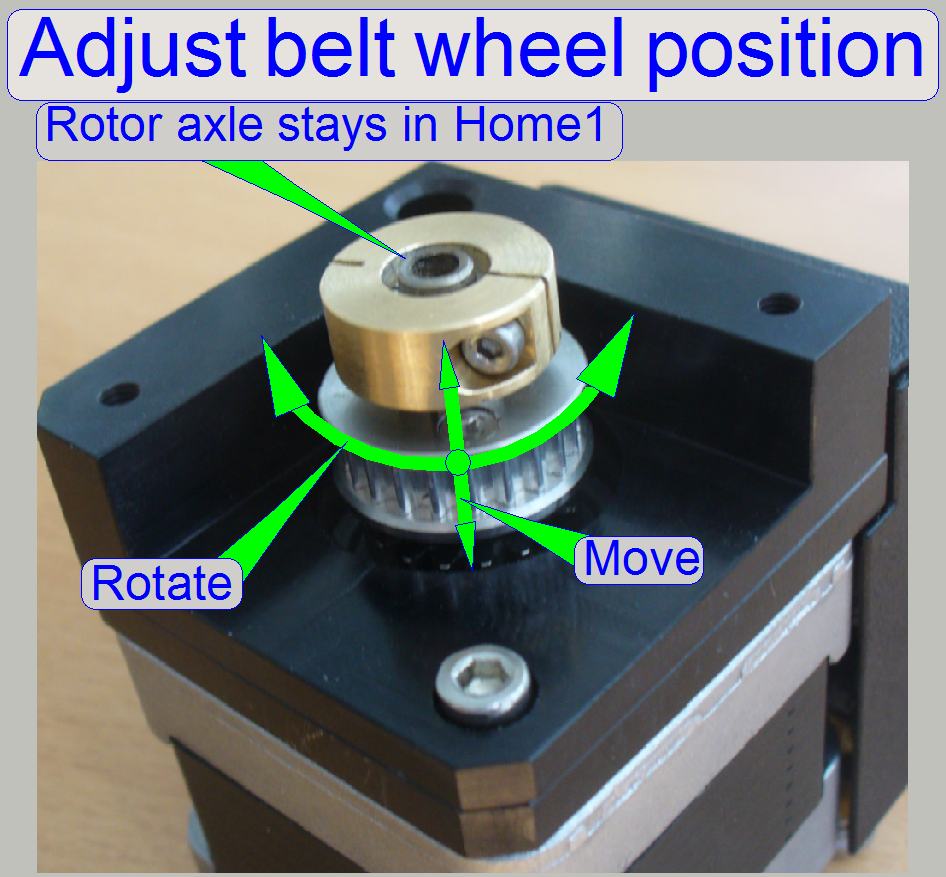
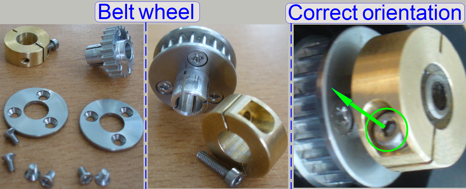 The belt
wheel transmits the force of the rotor to the belt. The position of the belt
wheel on the rotor axle is defined by the position of the belt leading rolls.
The belt
wheel transmits the force of the rotor to the belt. The position of the belt
wheel on the rotor axle is defined by the position of the belt leading rolls.
The diameter and the cog number of the belt wheel were
chosen so, that the exact distance of 3200 motor steps between two filter
positions is realized.
- The correct position of the belt wheel on the motor axle is fixed
by the belt wheel clamp.
- Mount the belt wheel onto the motor axle so, that the belt between
belt wheel and belt leading rolls is straight.
- By shifting the belt wheel on the motor axle, the straightness of
the belt can be reached.
- By rotating the belt wheel on the motor axle, the position of the
sensor “Home2” can be found and adjusted in relation to the sensor Home1.
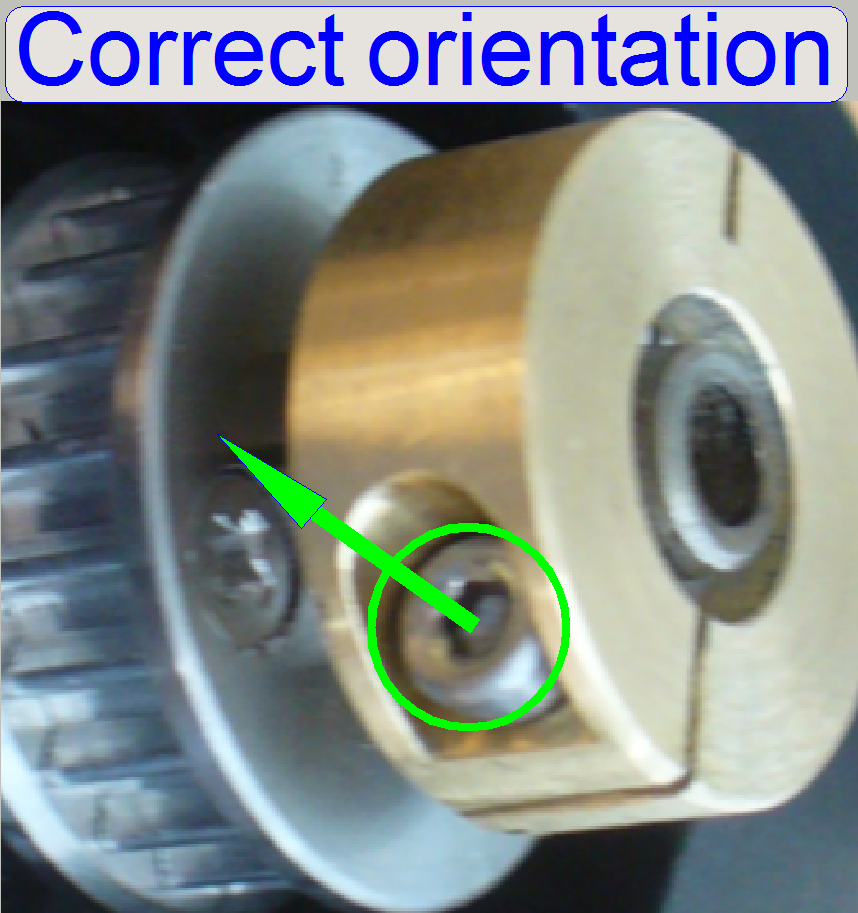
- To reach the belt wheel clamp’s fixing bolt with the 1.5 hex key
wrench, the orientation of the belt wheel clamp in relation to the belt
wheel is important; see also: “Loosen or
tighten the belt wheel clamp”
![]() “Find the
correct belt wheel position” and “Position of the belt
wheel’s clamp”
“Find the
correct belt wheel position” and “Position of the belt
wheel’s clamp”
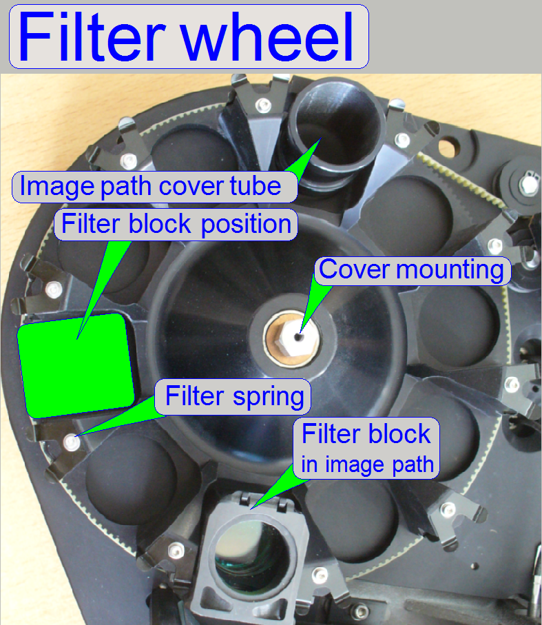 The
Filter wheel has 10 positions, so it is able to contain up to 9 filters and the
fluorescent tube for the brightfield scan procedure. The filter blocks are
fixed in their positions via springs. For bright field scanning and fluorescent
scanning also, in the 10th filter
position the image path cover tube must be inserted, or at least no filter
block must be inserted in this position.
The
Filter wheel has 10 positions, so it is able to contain up to 9 filters and the
fluorescent tube for the brightfield scan procedure. The filter blocks are
fixed in their positions via springs. For bright field scanning and fluorescent
scanning also, in the 10th filter
position the image path cover tube must be inserted, or at least no filter
block must be inserted in this position.
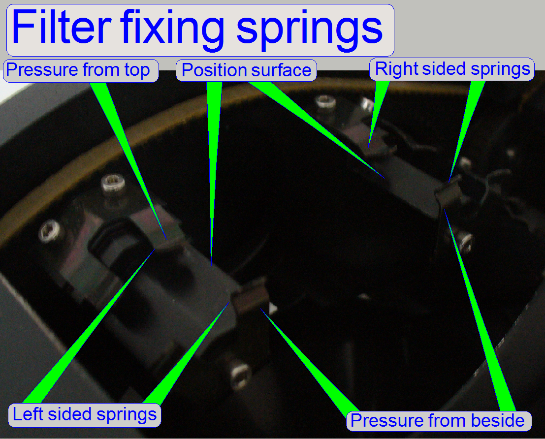 The filter
fixing springs are very sensitive in question of deforming, because these
springs guarantees the proper position of the filter block in relation to the
optical axis.
The filter
fixing springs are very sensitive in question of deforming, because these
springs guarantees the proper position of the filter block in relation to the
optical axis.
Any improper fixing of the filter in the filter wheel
(some 10th mm are important) modifies the “1st
filter position” of the incorrect inserted filter block and so the
straightness of the optical axis is also incorrect; this results in improper
exciting of the stained tissue and reduced image scan quality of the virtual
tissue; see also Check filter block
positions.
- Keep the position surfaces of the filter block and the filter wheel
clean and dry.
- During insertion or removal of the filter block take care on the
filter fixing springs; do the action carefully, without deforming the
springs.
Insert or remove filter blocks
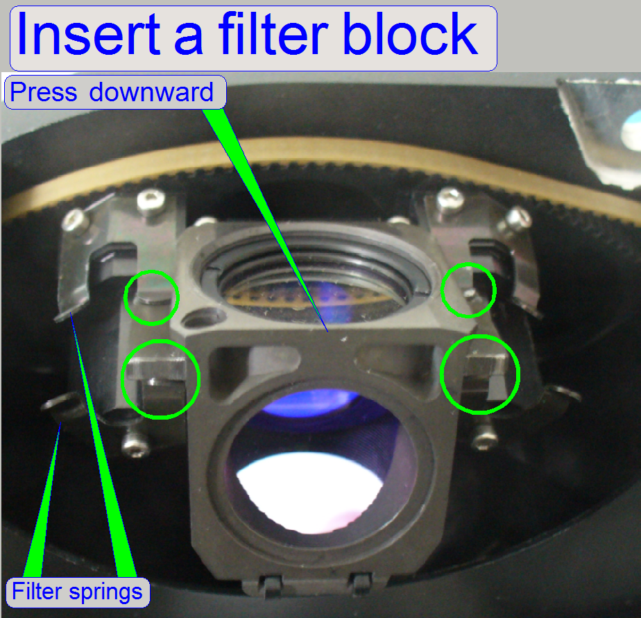 Fit the
filter block between the springs, into the filter block position of the filter
wheel as shown, then press the upper edge carefully downward until the sideward
pressing springs fixing the filter block correctly.
Fit the
filter block between the springs, into the filter block position of the filter
wheel as shown, then press the upper edge carefully downward until the sideward
pressing springs fixing the filter block correctly.
Check the proper position of the filter block in the
filter wheel manually; movements on the position surface must not occur.
To remove the filter block, lift up the filter block carefully
on the edge of the fixing springs from beside until the springs are even
disconnected, then move the entire filter block sideward.
- During the removal of the filter block, the springs on the top must
not be deformed!
Mechanical
drive
 The belt wheel on the motor axle drives the filter wheel via the
belt. The mechanical drive solution allows a filter position change with exact
3200 motor steps; in other words, the motor axle does one revolution to reach
the next or previous filter position. To move the filter wheel from the first
position to the 10th position the wheel goes 9 times 3200
steps forward or one filter position backward respectively.
The belt wheel on the motor axle drives the filter wheel via the
belt. The mechanical drive solution allows a filter position change with exact
3200 motor steps; in other words, the motor axle does one revolution to reach
the next or previous filter position. To move the filter wheel from the first
position to the 10th position the wheel goes 9 times 3200
steps forward or one filter position backward respectively.
The belt
leading rolls define the belt position in relation to the filter wheel;
because the filter wheel can be driven in both directions, two leading rolls
are used.
Because the belt wheel
can be moved (shifted) on the rotor axle of the motor, the adjusted
belt wheel position defines the straight movement of the belt during
rotation of the filter wheel.
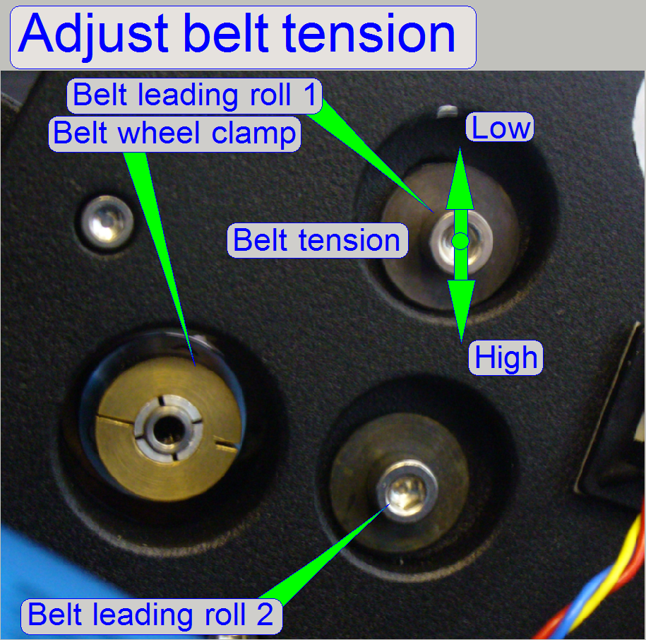
Adjust the belt tightness by positioning the leading
roll 1 upward or downward until no backlash can occur in the
filter position and the rotation of the filter wheel and the motor is done
nearly noiseless.
- Adjust
the belt tension by positioning the leading roll 1.
- The belt tightness is correct, if the filter wheel and the motor
rotates nearly noiseless; otherwise, if a backlash can occur in
the filter position, the tightness of the belt is too loosen.
- Check the correct movement of the filter wheel with the service
program forward and backward more times.
 The
filter wheel is designed to rotate endless, so the motor’s internal sensor “Home2”
can not be used to find the start position inside of 1 revolution of the filter
wheel.
The
filter wheel is designed to rotate endless, so the motor’s internal sensor “Home2”
can not be used to find the start position inside of 1 revolution of the filter
wheel.
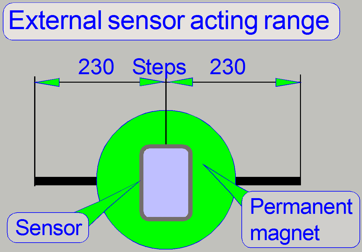
The start position of the filter wheel is defined by
the implemented permanent magnet; its position is exactly between the 3rd
and the 4th filter position on the filter wheel. The external Home2
sensor is implemented into the turret plate at the specified position; the
sensor is externally connected
to the stepper motor of the turret unit so, that the information of the motor’s internal Home2 sensor
is overridden.
- Because the permanent magnet is larger then the sensing surface of
the sensor, the acting range is about 450 steps.
![]() “Adjust the Home
sensor position” and “Check or adjust
the external sensor acting range”
“Adjust the Home
sensor position” and “Check or adjust
the external sensor acting range”
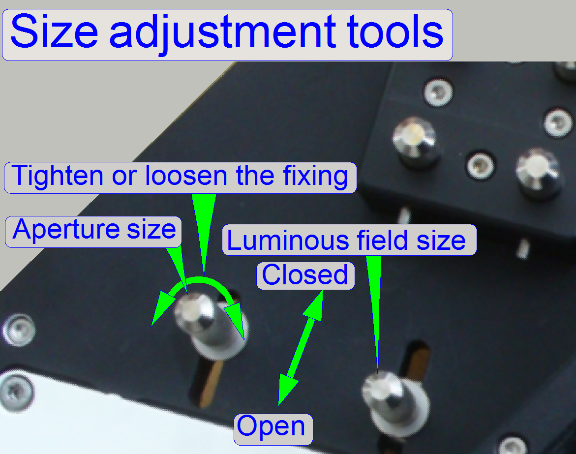
Diaphragm
position adjustment tools
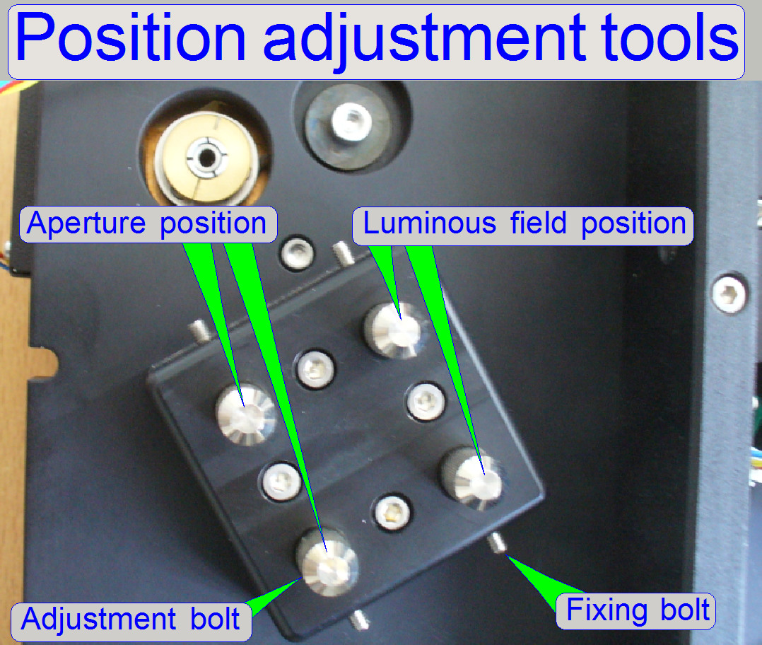
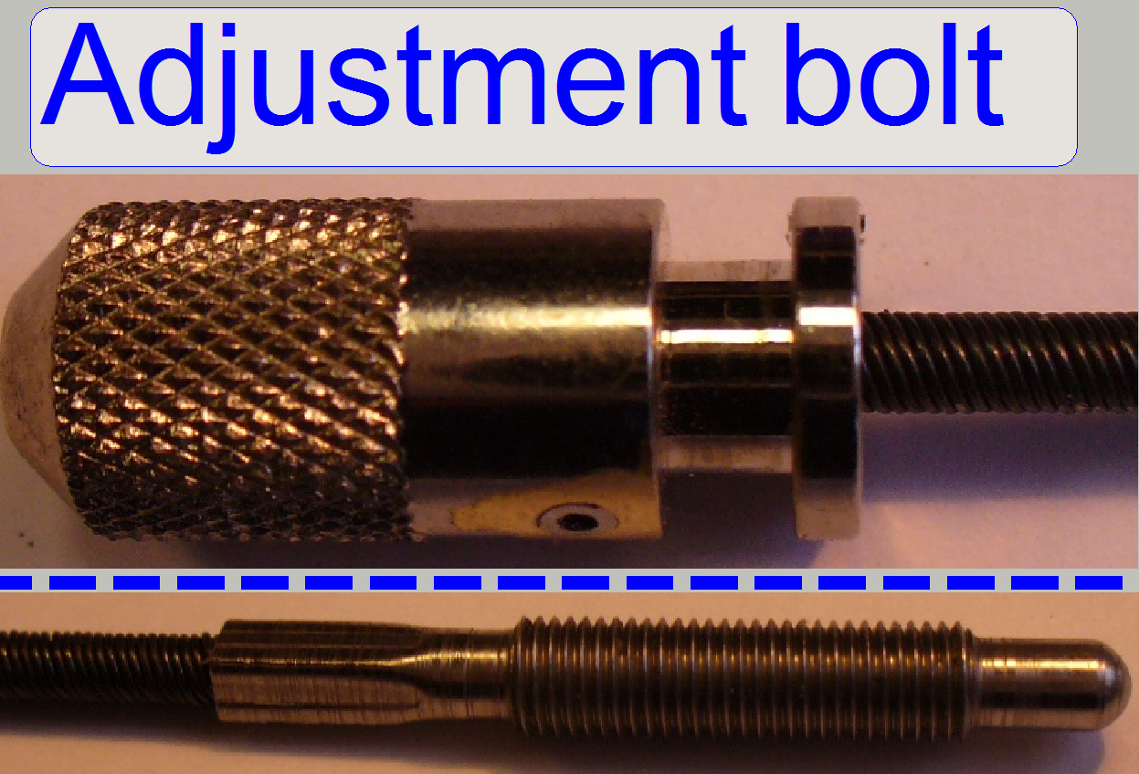
The adjustment bolts are used in a pair
of bolts with a shorter and a longer flexible shaft and these adjust the position of the
aperture and the luminous field diaphragm respectively in X- and
Y-direction in relation to the light beam. The fixing bolt is also used to
bearing the tool knob in the mounting. The fixing bolts for the other two tool
knobs are found on the opposite side, from the top. By removing the fixing bolt
the appropriate adjustment bolt can be dismounted, if necessary.
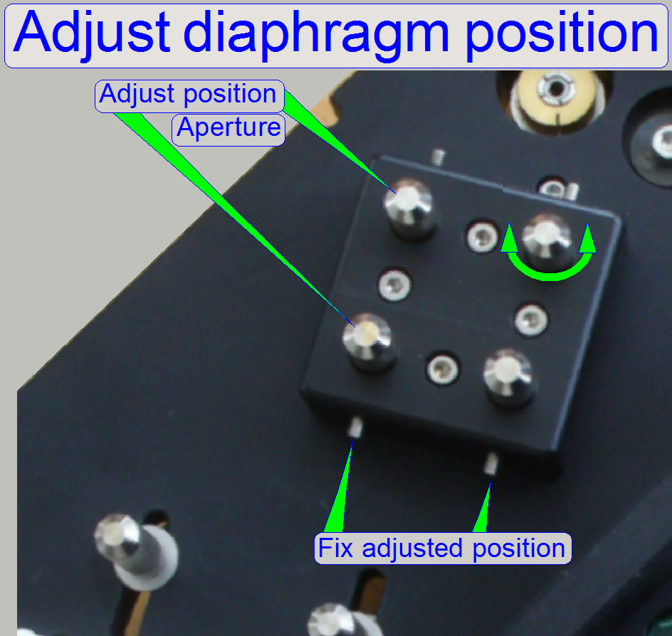 Handling the position adjustment tools
- Loosen the
“Aperture size” and / or the “Luminous field size” tool knob fixing.
- Loosen the appropriate position tool knob fixing bolt(s).
- Rotate the tool knob(s) until the desired position is reached.
- Tighten the tool knob fixing bolt(s) to fix the adjusted position.
Iris
size adjustment tool
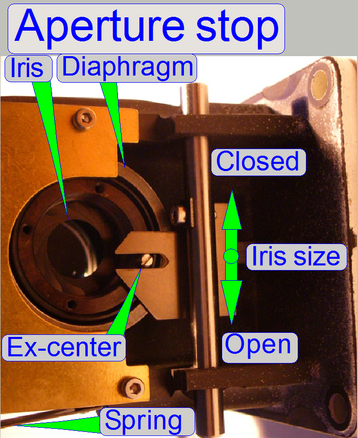
With the adjustment tools “Aperture size” and
“Luminous field size” the size of the iris can be defined via an ex-center. This
transforms the up / down movement of the “Aperture size” or “Luminous field
size” tool respectively to a rotation of the iris mechanics and this will more
open or more close the iris.
Both tools can be fixed separately by screwing the
tool knob.
If the spring was dismounted or is not fixed properly,
there exists the possibility that the ex-center is disconnected from the bolt
of the iris mechanics. In this case, you are unable to adjust the iris size.
Check the connection between ex-center and iris bolt always after reassembling.
If the open / close tool is fully pulled or fully pushed, disconnection must
not occur. Check this behavior in various end positions of the adjustment bolts
also!
Handling the size adjustment
tools
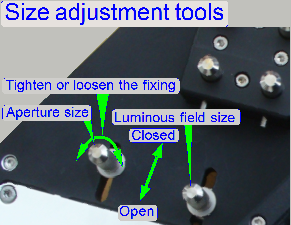 Loosen the
tool knob fixing.
Loosen the
tool knob fixing.- Move the tool knob up / down until the desired size of the aperture
or the luminous field respectively is found.
- Tighten the tool knob fixing.
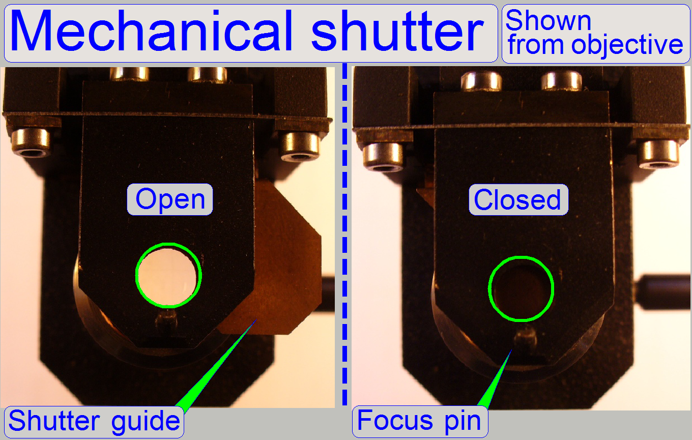
The mechanical shutter is implemented as a part of the focus unit. The
shutter must be closed during fluorescent scanning and insures a dark background.
Other, unwanted fluorescent materials (e.g. painting, optics) can not reflect
the fluorescent light or can not fluoresce and so they will not disturb the
fluorescent view.
![]() “Focus
unit’, and “Shutter mechanics”
“Focus
unit’, and “Shutter mechanics”
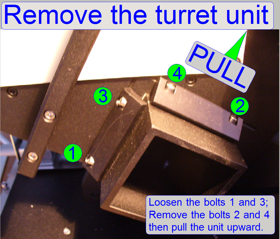
Remove the
turret unit from the scanner
1. Remove the camera changer unit (if
exchange).
2. Remove
the cable FCJ-1 from the turret stepper motor.
3. Remove
or loosen respectively the mounting bolts for the turret unit as shown.
4. Pull
the entire fluorescent reflector turret unit in an angle of approximately 30
degrees upward and frontward.
Insert and mount the reflector turret unit
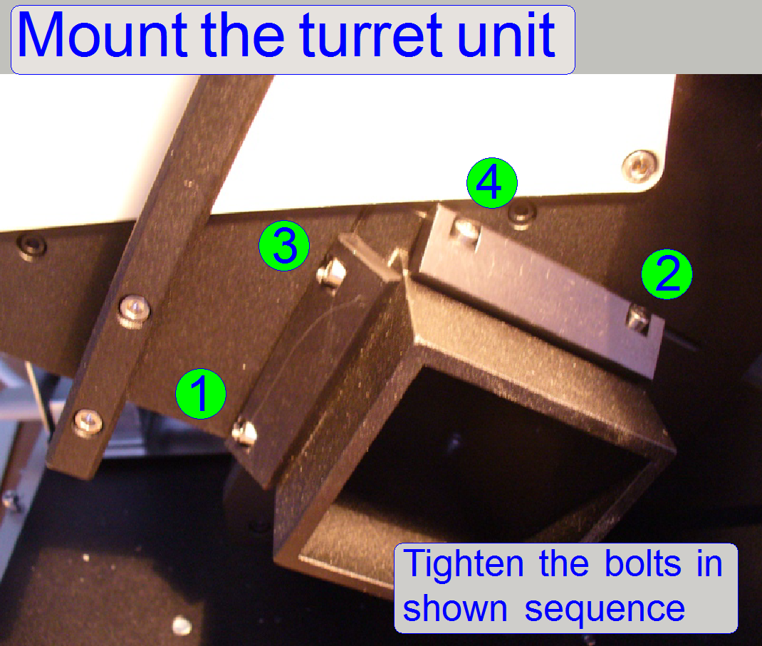
Because the camera changer unit mounting is a part of
the turret unit and the straightness of the optical axis depends highly on the correct
mounting of the turret plate also the tightening sequence of the clamp mounting
bolts is very important.
During tightening the clamp bolt (1) move the turret
unit (turret plate) on its upper part carefully toward and away from the
scanner unit until no movements can be experienced; then tighten the clamp bolt
(2); only this way, the locating surface will fit correctly. The sequence of
the bolts (3) and (4) is less important because these bolts are near to each
other.
1.
Insert the (new) reflector turret unit.
2.
Tighten the bolts in the sequence from 1
to 4 as shown.
3.
Connect the turret stepper motor cable FCJ-1.
4.
Mount the camera changer unit.
After the new turret
unit was mounted, the adjustments should be checked and the appropriate
parameters of the file “MicroscopeConfiguration.ini” sections [ReflectorTurret]
must be updated, and the file must be saved. In all cases the chromatic aberration and the camera rotation
angle must be checked / adjusted; see also “Stitching”.
Optical
components
Exciting
light source adapter mounting
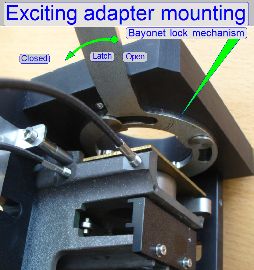 The FL
light source mounting interfaces and connects the appropriate adapter via a
bayonet lock mechanism; with this solution, the light source may be mounted /
dismounted very quickly and allows the connection of different types of light
sources.
The FL
light source mounting interfaces and connects the appropriate adapter via a
bayonet lock mechanism; with this solution, the light source may be mounted /
dismounted very quickly and allows the connection of different types of light
sources.
Adapters
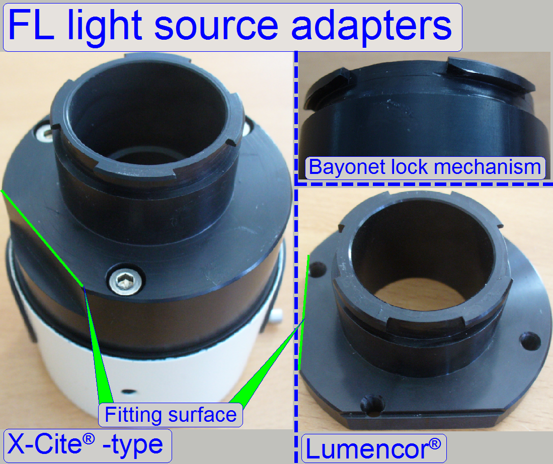 Momentarily
two types of adapters are available, the Lumencor® adapter and the X-Cite® type adapter.
Momentarily
two types of adapters are available, the Lumencor® adapter and the X-Cite® type adapter.
- Open the latch, insert the adapter into the adapter mounting until
it stops and close the latch.
EPI-fluorescent illumination
unit
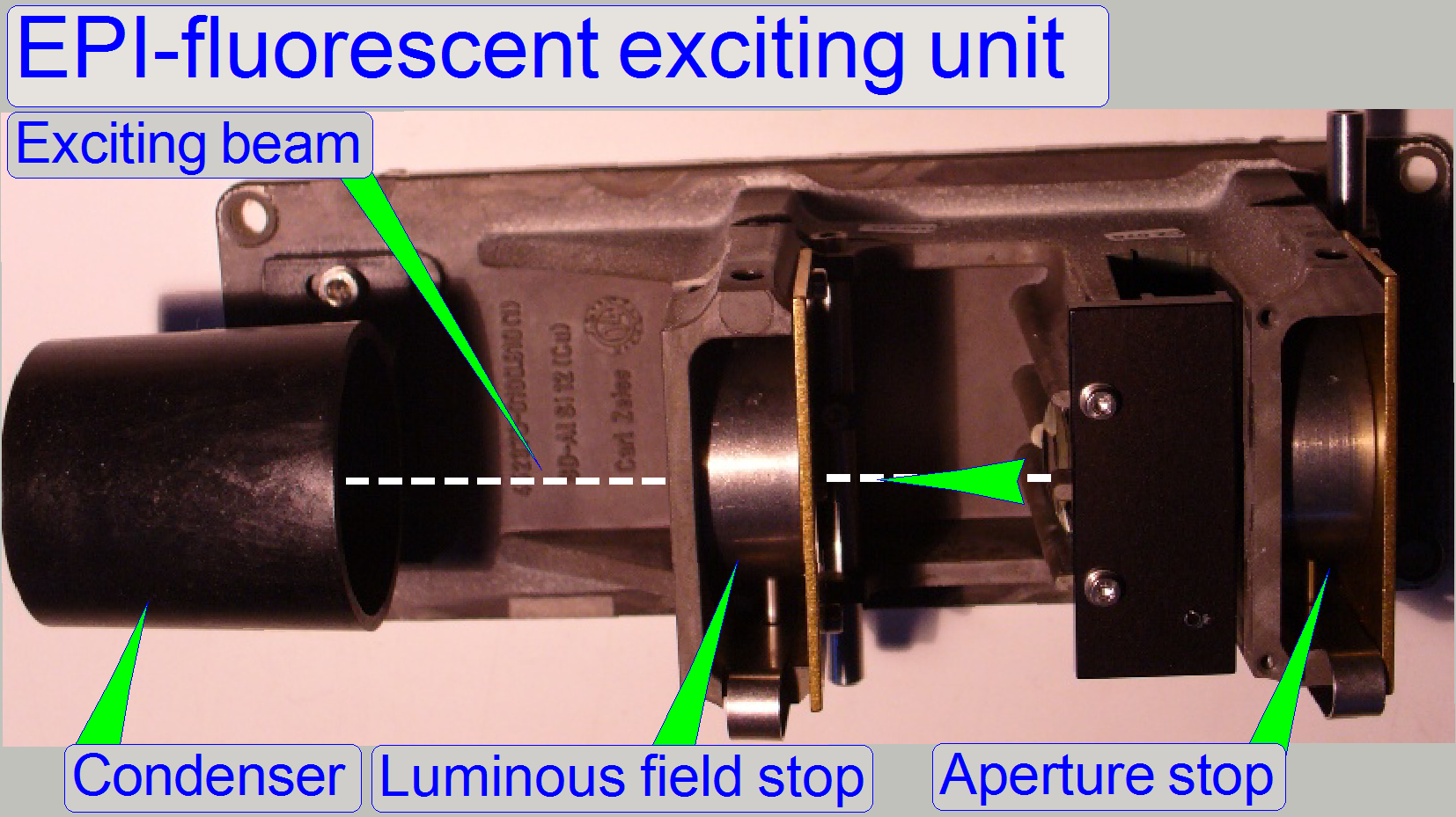 The aperture stop (a metal device
that limits the amount of light going through the system), the luminous field stop
(a metal device that limits the area of the visible field) and the condenser (a
lens that serves to concentrate light from the exciting source that is in turn
focused through the object) are situated on the “EPI-Fluorescent
illumination unit”. The mechanical construction of the aperture stop and
the luminous field stop is identical.
The aperture stop (a metal device
that limits the amount of light going through the system), the luminous field stop
(a metal device that limits the area of the visible field) and the condenser (a
lens that serves to concentrate light from the exciting source that is in turn
focused through the object) are situated on the “EPI-Fluorescent
illumination unit”. The mechanical construction of the aperture stop and
the luminous field stop is identical.
![]() “Iris size adjustment
tool”; “Handling
the size adjustment tools”;
“Iris size adjustment
tool”; “Handling
the size adjustment tools”;
“Position of the
diaphragm”; Handling
the position adjustment tools” and “Condenser”.
Position
of the diaphragm
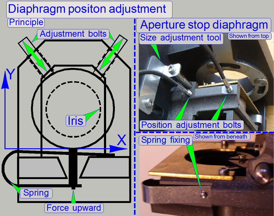
The diaphragm of the aperture stop and the luminous
field stop are forced upward by a spring. By driving the adjustment bolts in or
out a limited movement in the X- and Y-direction of the diaphragm can be
performed; so the iris will be centered in relation to the beam. Very important
in this construction is the force of the spring. If the force of the spring is
too low (the spring is not inserted well or mechanical jamming between
diaphragm and housing occurs) the diaphragm can not be adjusted or only in a very
small range. If there is any problem with positioning the diaphragm, check the
easy movement of the diaphragm manually, the proper position of the spring and
the drive mechanics of the adjustment bolts.
Take into account, that the “Aperture size” or the
“Luminous Field size” tool respectively can prevent the appropriate diaphragm
from movement, even if it’s fixing is tightened!
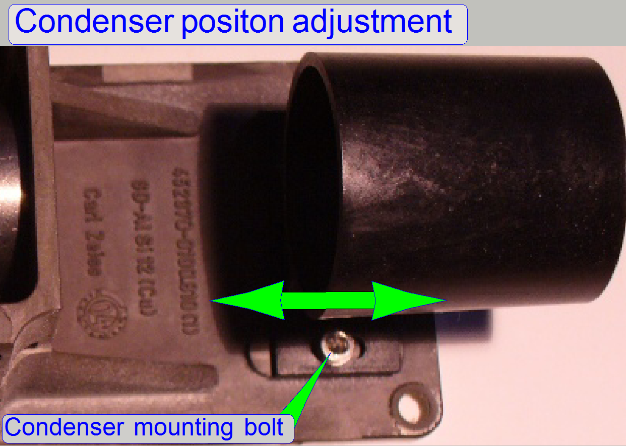
By loosening the fixing bolts on both sides of the
condenser the focus position can be adjusted by moving it toward or away
respectively from the luminous field stop. The condenser is mounted
perpendicular to the fluorescent light beam. If the condenser’s focus is
reached, a sharp view of the iris of the luminous field stop is visible on the
live view even if the luminous field size is smaller then the image size of the
camera.
·
Keep the lens surfaces of the condenser clean
 “Cleaning
optics” and Condenser
“Cleaning
optics” and Condenser
Mirror
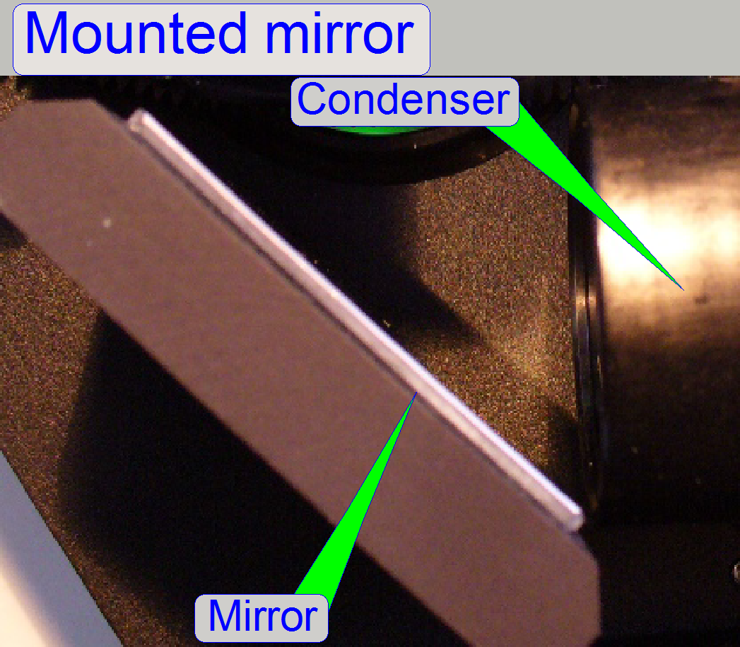 The
mirror is mounted at an angle of 45 degrees to the light beam and reflects the
excitation light to the filter block.
The
mirror is mounted at an angle of 45 degrees to the light beam and reflects the
excitation light to the filter block.
- The mirror does not need adjustments.
- Keep the mirror surface clean; see also: “Cleaning optics”.
Filter
block
 The filter
sets for fluorescent scan
exist in various filter
combinations to filter the light of a specific wavelength to excite the
fluorescent stain of the tissue (Excitation filter)
and to filter the relevant, emitted light of the stained tissue (Emission
filter). The beam splitter reflects the shorter light wavelength during the
light with the longer wavelength passes thru it. The filter sets are assembled
to a filter
block or filter cube. The wavelength varies in the range between ultra violet excitation (350 nm) -
blue emission (450 nm) and orange excitation (600 nm) - deep red
emission (690 nm). A wide
spectrum of filter sets or filter blocks is available from major microscope
manufacturers via
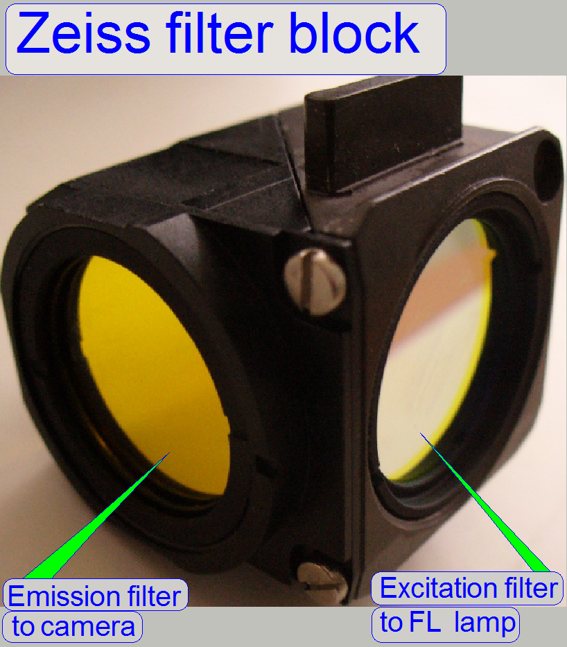
product number. If you are self assembling the filter set into a block, take care
on the positions where the filters are mounted. The Emission filter shows
always to the camera and the Excitation filter to the fluorescent light source.
The Excitation filter, the Emission filter and the Beam splitter are combined
for a special light wave length and therefore they must not be mixed with parts
of another set!
The filter
sets for fluorescent scan
exist in various filter
combinations to filter the light of a specific wavelength to excite the
fluorescent stain of the tissue (Excitation filter)
and to filter the relevant, emitted light of the stained tissue (Emission
filter). The beam splitter reflects the shorter light wavelength during the
light with the longer wavelength passes thru it. The filter sets are assembled
to a filter
block or filter cube. The wavelength varies in the range between ultra violet excitation (350 nm) -
blue emission (450 nm) and orange excitation (600 nm) - deep red
emission (690 nm). A wide
spectrum of filter sets or filter blocks is available from major microscope
manufacturers via
product number. If you are self assembling the filter set into a block, take care
on the positions where the filters are mounted. The Emission filter shows
always to the camera and the Excitation filter to the fluorescent light source.
The Excitation filter, the Emission filter and the Beam splitter are combined
for a special light wave length and therefore they must not be mixed with parts
of another set!
![]()
·
„Filter
block”; Zeiss filter
·
Fluorescent exciting
·
 “Matching
Fluorescent Probes with Nikon Fluorescence Filter Blocks”; interactive
“Matching
Fluorescent Probes with Nikon Fluorescence Filter Blocks”; interactive
·
‘Introduction
to Fluorescence Filters” (Semrock)
· “Setup filters” (to
assign colors, color channels, and filter positions)
·
- Keep the surfaces of the excitation filter
and the emission filter clean; see also: “Cleaning
optics”
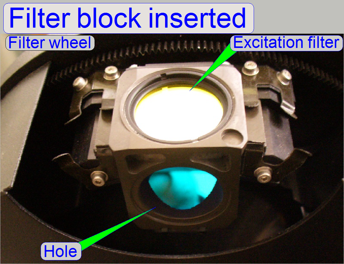 When the filter block is inserted properly into
the reflector turret filter wheel, the springs are fixing the filter block in
its position and no further adjustments are needed.
When the filter block is inserted properly into
the reflector turret filter wheel, the springs are fixing the filter block in
its position and no further adjustments are needed.
The “hole” in the filter block (opening without
filter) shows always to the objective.
- The proper position of the filter block is reached, if the springs
on the top are pressing the filter block onto the position surface and the
springs from beside are pressing the filter block toward the belt!
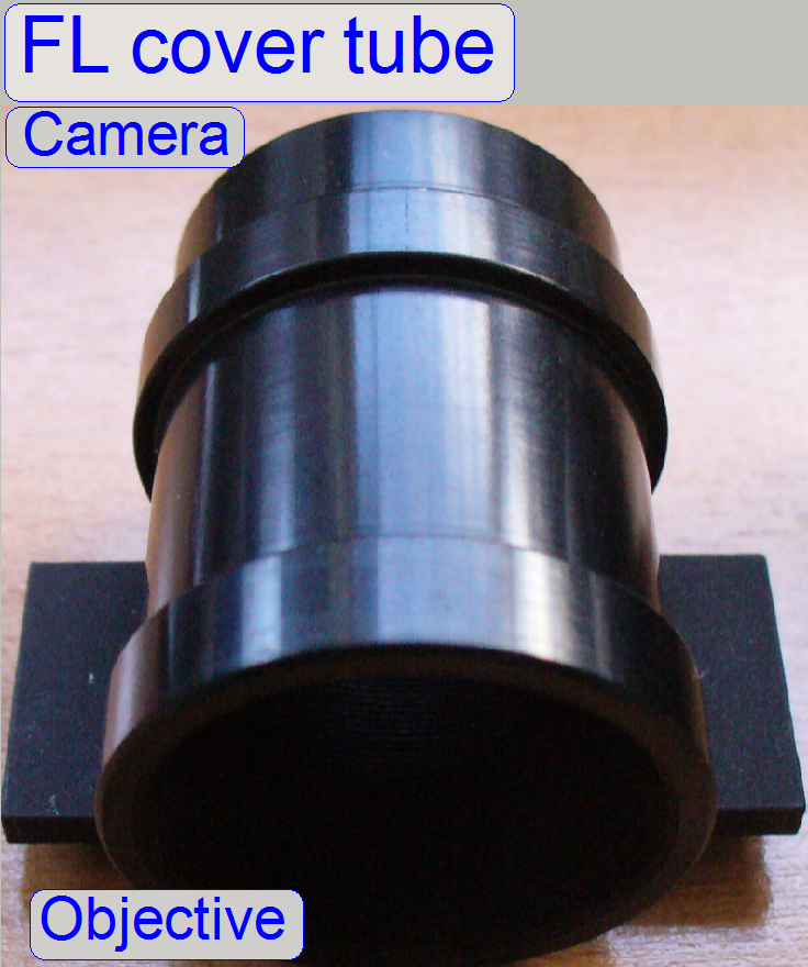 The
fluorescent cover tube does not contain optics, it is always used in the 10th filter position of the filter wheel;
it covers the image path and is inserted and mounted like a filter block.
The
fluorescent cover tube does not contain optics, it is always used in the 10th filter position of the filter wheel;
it covers the image path and is inserted and mounted like a filter block.
Virtual
tissue
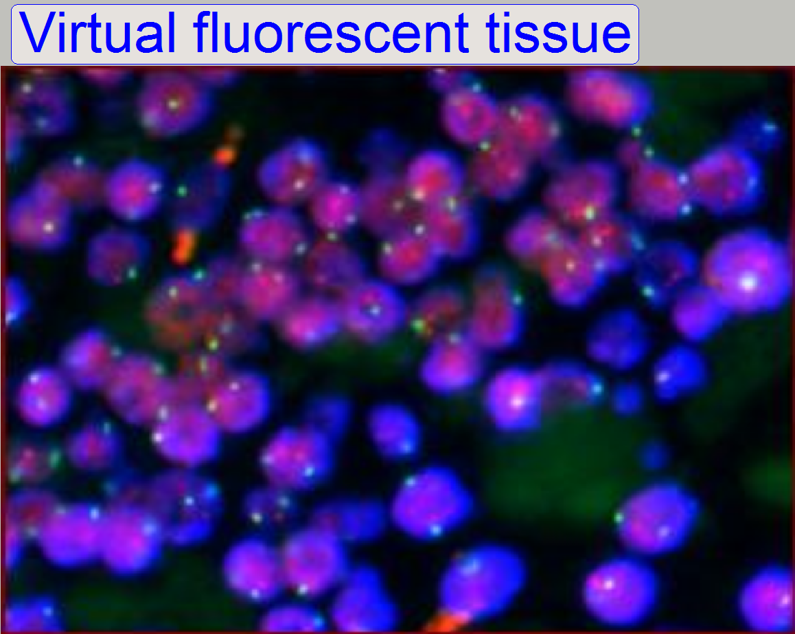 To allow
analyzing of parts in the tissue (e.g. nuclei, or DNS fractions), parts can be stained with special stain. A
wide range of fluorescent stains (fluorophores) is available for different markers.
Each stain is excited by a special wave length of the excitation light and
emits light in another, relevant wavelength. One tissue can be stained with
more than only one stain (fluorophore), so different parts of the tissue can be
visualized in different colors at the same time.
To allow
analyzing of parts in the tissue (e.g. nuclei, or DNS fractions), parts can be stained with special stain. A
wide range of fluorescent stains (fluorophores) is available for different markers.
Each stain is excited by a special wave length of the excitation light and
emits light in another, relevant wavelength. One tissue can be stained with
more than only one stain (fluorophore), so different parts of the tissue can be
visualized in different colors at the same time.
To reduce the exposure time of the camera and to
produce a high quality of the virtual fluorescence tissue, the used filter
block must match the excitation wavelength (the source wave length to excite
the stain) AND the emission wavelength (the emitted wavelength of the stain)
also. Furthermore, the emitted wavelength of the exciting light source must be
able to excite the stain in its wavelength.
To produce a high quality of the virtual fluorescent
tissue and to reduce the exposure time during fluoresce scan the following
parameters are very important:
1) The characteristic of the exciting
light source (emitted wave lengths)
2) The characteristic of the used
filter block (exciting and emission wave length) and
3) The characteristic of the used
stain (exciting and emitted wave length).
The best virtual tissue quality (and the shortest
exposure time also) will be reached if all the characteristics are optimal met,
otherwise the exposure time will rise up and the virtual tissue becomes more
poor.
If the wave lengths of one component differ too much,
the scanned quality is very poor or even bad!!
More information about Fluorescence
Microscopy!
- Keep the surface of the cover slip and the surface of the slide
bottom clean; see also: “Cleaning optics”
Autocollimator
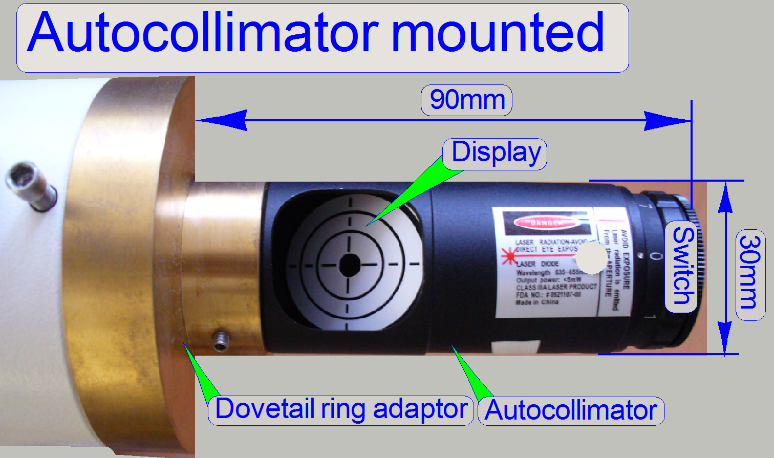 An autocollimator is an optical instrument for non-contact measurement of angles. They are typically
used to align components and measure deflections in optical or mechanical systems. An autocollimator
works by projecting an image onto a target mirror, and
measuring the deflection of the returned image against a display with a scale,
either visually or by means of an electronic detector. A visual autocollimator
can measure angles as small as 0.5 arc seconds.
An autocollimator is an optical instrument for non-contact measurement of angles. They are typically
used to align components and measure deflections in optical or mechanical systems. An autocollimator
works by projecting an image onto a target mirror, and
measuring the deflection of the returned image against a display with a scale,
either visually or by means of an electronic detector. A visual autocollimator
can measure angles as small as 0.5 arc seconds.
Precautions
Never look directly into
the beam of the autocollimator!
The LASER beam has often a power of 0.1W only, but this is enough to
harm the retina of the eye!

The dovetail ring adapter is used to interface the
autocollimator to the adapter for X-cite type fluorescent exciting sources and
the check camera.
FL adapter for
X-cite-type light sources
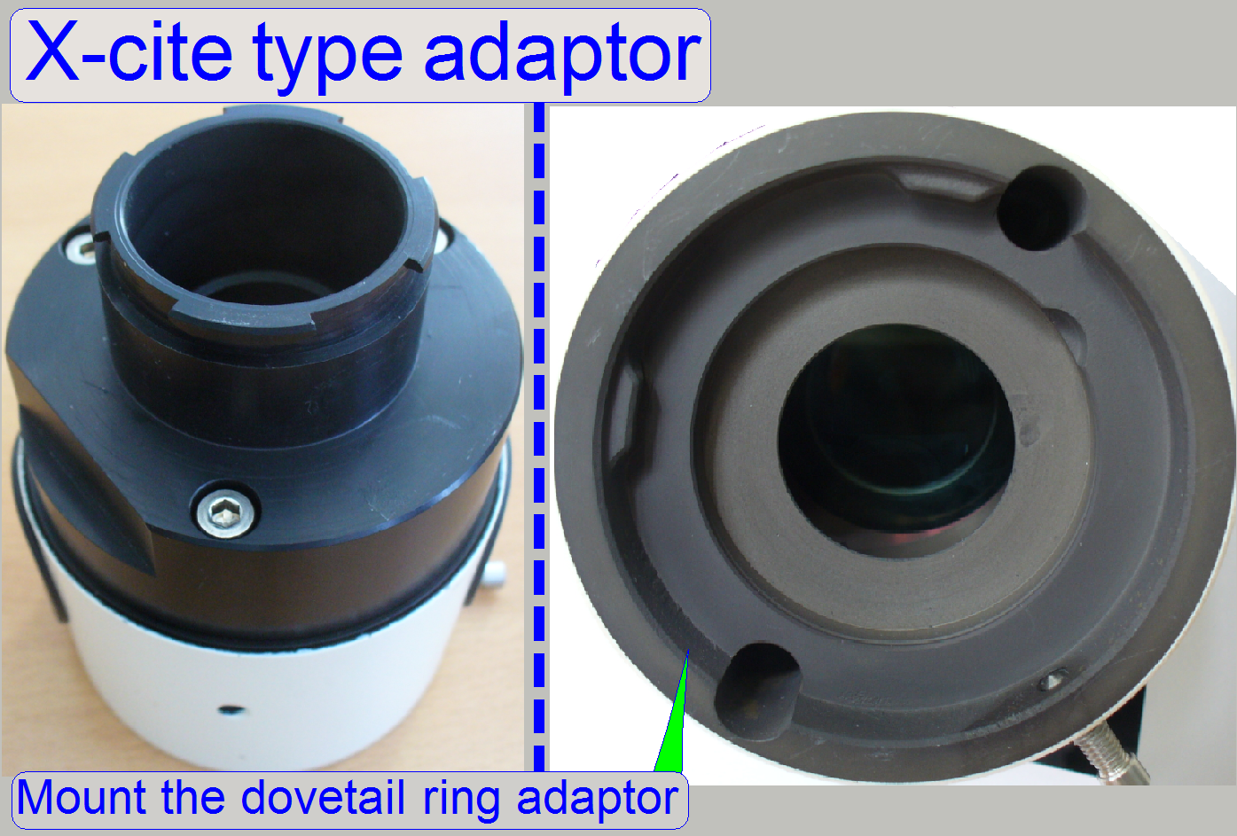
This adapter is used to connect the adjustment tools
to the turret unit, because the tools are equipped with a dovetail ring
adaptor.
 For
adjustments, a green filter block is necessary. Nevertheless, the finished
adjustments should be checked with the filter set of the user.
For
adjustments, a green filter block is necessary. Nevertheless, the finished
adjustments should be checked with the filter set of the user.
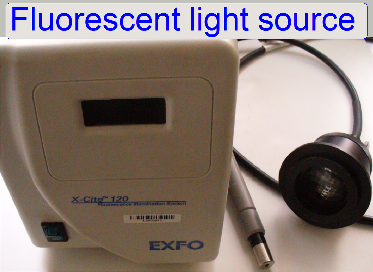
· The light
source is used to illuminate the stained tissue during the fluorescent scan
process. Depending on the light source, found by the user, the X-cite® type
light engine or the Lumencor SPECTRA light engine® is used to define the
luminous field size.
X-Cite type FL light source
Precautions
 Never look directly into the beam of the fluorescent
light source! The lamp emits also ultraviolet light with very high intensity.
To prevent your eyes from harm (damage) use always sun glasses with a high
filter factor of UV light if the fluorescent light source is switched on and
you are adjusting the beam even if the cover of the turret unit is removed. For
further precautions please, refer to the manual for the fluorescent light
source you are using!
Never look directly into the beam of the fluorescent
light source! The lamp emits also ultraviolet light with very high intensity.
To prevent your eyes from harm (damage) use always sun glasses with a high
filter factor of UV light if the fluorescent light source is switched on and
you are adjusting the beam even if the cover of the turret unit is removed. For
further precautions please, refer to the manual for the fluorescent light
source you are using!
· This
type of light sources generates all exciting wave lengths at the same time; a
white light beam is created. With this light source only single band filters
can be used.
Lumencor
SPECTRA light engine®
 Precautions
 Never look directly into the beam of the fluorescent
light source! For further precautions please, refer to the manual for the
fluorescent light source you are using!
Never look directly into the beam of the fluorescent
light source! For further precautions please, refer to the manual for the
fluorescent light source you are using!
· This
light source generates monochromatic exciting wave lengths; the desired wave
length can be selected by software. With this light source single band or multi
band filters can  be used likewise.
![]() “Lumencor SPECTRA light
engine®”
“Lumencor SPECTRA light
engine®”
Auxiliary
illumination (optional)
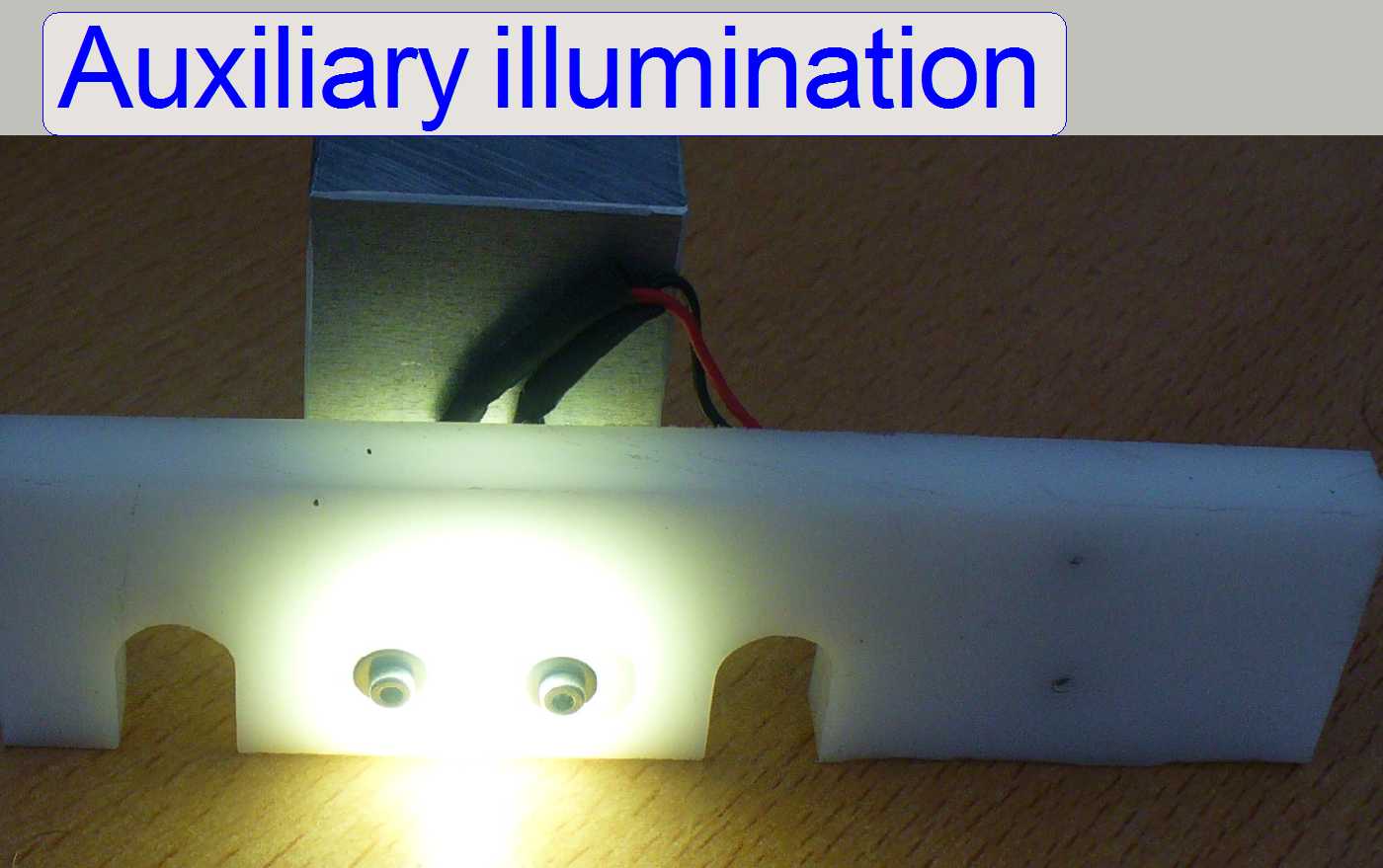 Because
the flash frequency of the flash illumination is very slow if controlled via
the service program, the auxiliary illumination is used to illuminate the
fluorescent illumination path and so the adjustment of the aperture diaphragm
position and the size of the aperture iris can be done.
Because
the flash frequency of the flash illumination is very slow if controlled via
the service program, the auxiliary illumination is used to illuminate the
fluorescent illumination path and so the adjustment of the aperture diaphragm
position and the size of the aperture iris can be done.
Auxiliary
illumination mounted
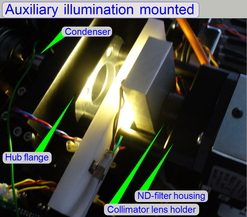 Press
the “Auxiliary illumination” carefully onto the rods of the ND filter unit,
between the
collimator lens holder and the hub flange until the illumination stops.
Connect the illumination to any USB 2.0 port.
Press
the “Auxiliary illumination” carefully onto the rods of the ND filter unit,
between the
collimator lens holder and the hub flange until the illumination stops.
Connect the illumination to any USB 2.0 port.
Check camera (optional)
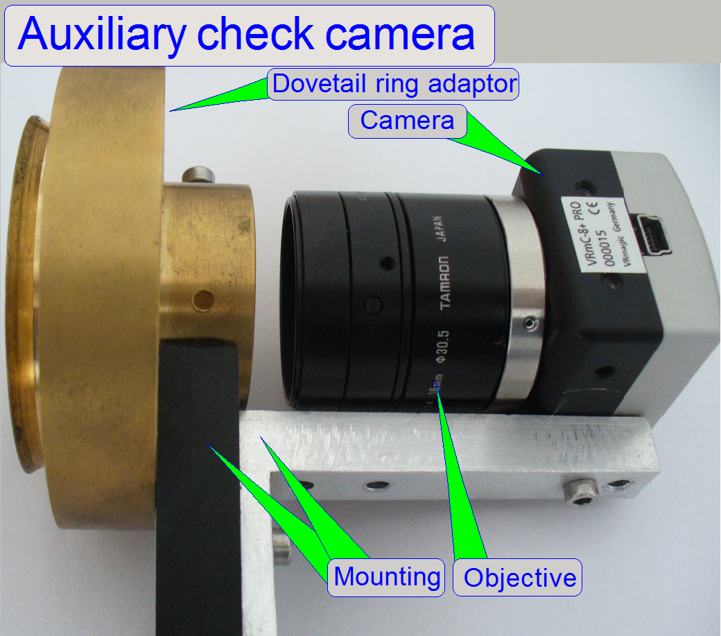 The
check camera (VRmc-8+ PRO)
and the objective (TAMRON 23FM16SP),
together with the auxiliary illumination it is used to make the position and
the size of the aperture stop iris visible; adjustment details are visible on
the screen.
The
check camera (VRmc-8+ PRO)
and the objective (TAMRON 23FM16SP),
together with the auxiliary illumination it is used to make the position and
the size of the aperture stop iris visible; adjustment details are visible on
the screen.
· The
mounting with a dovetail ring adaptor allows the use of the check camera for
the PMIDI and the PSCAN type scanners also.
Requirements
To make the aperture iris visible on the screen by the
use of this camera “VRmagic”, the “VRmagic Cam Lab” is required!
Setup in the software version 1.16 VRmUsbCam
DevKit for Windows (x86) 3.15b.msi
Setup in the software version 1.15 VRmagic
USB Camera Development Kit 3.13g.msi
· The
camera uses an USB 2.0 port, otherwise, if the transfer rate of 480Mb/s can not
be reached (USB1.1 or lower), the camera window will disappear automatically
after some seconds, without any notice!!
Check
camera mounted
 Mount
the check camera onto the X-Cite® type adapter and connect it to
any USB 2.0 port. Memorize the serial number of the camera.
Mount
the check camera onto the X-Cite® type adapter and connect it to
any USB 2.0 port. Memorize the serial number of the camera.
![]() “The preview
camera VRmagic” and “The
program CamLab”
“The preview
camera VRmagic” and “The
program CamLab”
The
adjustment of the FL reflector turret unit includes:
- Loosen
or tighten the belt wheel clamp
- The
position of the belt wheel’s clamp
- Find
the correct belt wheel position
- Adjust
the tension of the belt.
- Check the
backlash of the filter position
- Adjust
the Home sensor position
- Find
the Home position of the filter wheel.
- Check
and adjust the external sensor acting range
- Find
the 1st filter position.
- Adjust the position of the aperture stop diaphragm
- Adjust the size of the aperture stop diaphragm.
- Adjust the position of the luminous field stop diaphragm.
- Check the filter block positions in the filter wheel.
- Adjust the size of the luminous field stop diaphragm.
The appropriate adjustment should be
done:
- If the home positions Home1 and Home2 (with the service program,
Low Level Service) cannot be reached (adjust the
home position); check the
functionality of the external Home2 sensor.
- If motor steps are lost during Home1 and Home2 will be reached (check the
tightness of the belt).
- If moving to any filter position causes lost motor steps (check the
tightness of the belt; check for unwanted pieces in the turret unit that
may cause lost steps).
- If the belt wheel clamp bolt on the stepper motor axle was loosened
(adjust
the home position; define the 1st
filter position).
- If the stepper
motor had been exchanged
(check the
tightness of the belt; adjust the
home position; define the 1st
filter position).
If an error of the type named above occurs please, switch off the power
supply and remove all the filters from the filter wheel manually. If any
filter is inserted wrong one of the named behavior can occur also. Check also
for unwanted / unexpected mechanical parts inside the turret unit which can
inhibit the wheel from correct movement. After all filters are removed check
the mechanical drive again with the Low Level Service part of the service
program. Check the home positions Home1 and Home2; and check the 1st
filter position, compare it with the appropriate parameter of the file
“MicroscopeConfiguration.ini” section [ReflectorTurret].
Check and adjust the belt tension
·  If the
movement range of the belt leading roll 1 is not enough to reach the required
tension, increase the tension of the belt with the leading roll 2 and then
adjust the tension with the leading roll 1.
If the
movement range of the belt leading roll 1 is not enough to reach the required
tension, increase the tension of the belt with the leading roll 2 and then
adjust the tension with the leading roll 1.
Adjust the tension of the belt if:
- The belt leading roll 1 or 2 was loosened.
- The motor was removed or exchanged.
- The movement of the filter wheel or the motor is noisy (in the scan
program or in the service program with correct u-time).
- The backlash
of the filter position is too much.
1.
Loosen the belt leading roll 1 until it
becomes moveable.
2.
Move the mounting bolt downward with a force
of about 100 - 200gram and tighten the belt leading roll 1 mounting bolt.
3.
Rotate the filter wheel some revolutions
forward and backward (with the service program).
The filter wheel and the motor moves correctly, if the
movement sound is scarcely audible.
Check
the backlash of the filter wheel also; a backlash should not be
experienced.
Check also the
straightness of the belt between the belt wheel and the filter wheel.
- If a sanding, sliding or strong moving sound is audible, the u-time of the motor may be
incorrect (service program) or the belt is too much tightened (scan
program).
Check the backlash of the filter position
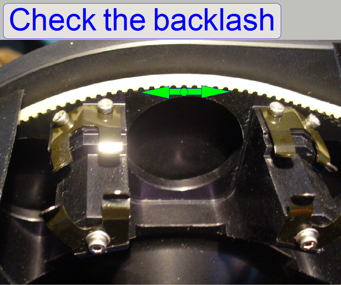 Try to
move the filter wheel manually forward and backward a little bit.
Try to
move the filter wheel manually forward and backward a little bit.
- If the belt is not tightened enough, a small movement can be
experienced.
![]() “Check or adjust the
belt tension”
“Check or adjust the
belt tension”
Loosen
or tighten the belt wheel’s clamp
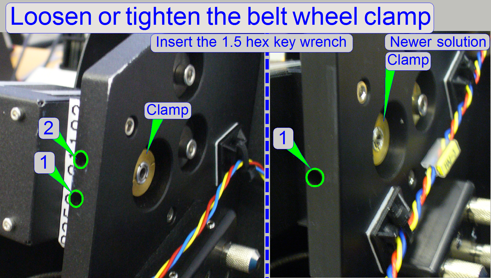 Rotate the
filter wheel manually or rotate the motors axle with the service program until
the bolt of the belt wheel clamp can be reached with the 1.5 hex key
wrench thru the drillings (1) or (2).
Rotate the
filter wheel manually or rotate the motors axle with the service program until
the bolt of the belt wheel clamp can be reached with the 1.5 hex key
wrench thru the drillings (1) or (2).- After loosening the belt wheel clamp, the belt wheel can be rotated
and / or moved on the motor axle or the rotor can be rotated as required.
 Adjust
the belt wheel position and tighten the belt wheel clamp.
Adjust
the belt wheel position and tighten the belt wheel clamp.
- Because in newer versions of
the belt driven turret unit only one drilling can be found, the correct
orientation of the belt wheel clamp in relation to the belt wheel becomes
important. In earlier versions the orientation of the belt wheel clamp was
unimportant!
Position of the
belt wheel’s clamp
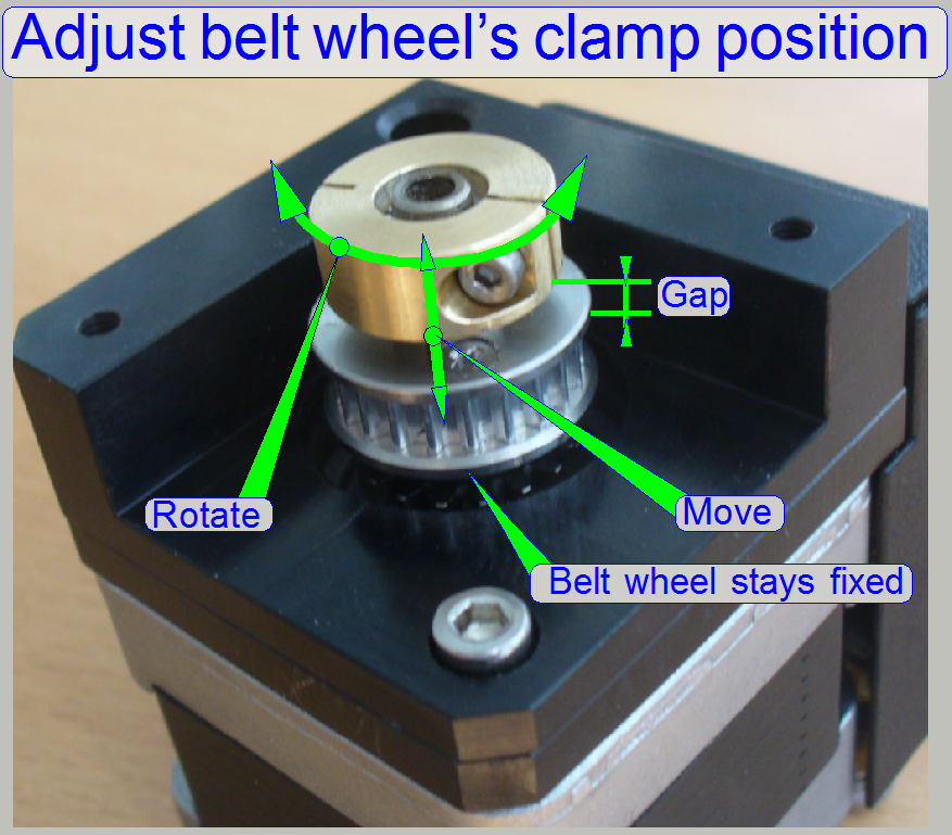
- The clamp of the belt wheel can also be rotated / moved in relation
to the belt wheel.
·
Rotate the stepper motor axle with the
service program until the belt wheel clamp’s fixing bolt can be reached thru the holes 1 or
2 and loosen the belt wheel’s clamp.
·
Set the stepper motor to the position
Home1, fix the filter wheel by hand against rotation (so the belt wheel can
also not move) and then rotate the belt wheel’s clamp to the position where the
fixing bolt can be reached thru the holes 1 or
2.
·
Check the result; repeat the procedure
more times until all positions are correct.
- Move the belt wheel clamp in direction to the belt wheel side wall
until the gap is closed.
Find
the correct belt wheel’s position
- The belt wheel position on the motor axle is defined by the
position of the belt leading rolls (move the belt wheel on the rotor axle)
and the Home2 state (rotate the belt wheel in relation to the rotor axle).
- By moving the belt wheel on the rotor axle in relation to the belt
leading rolls, the correct position of the belt wheel can be found, so the
belt will move straight during the drive of the filter wheel.
- By rotating the belt wheel on the rotor axle the correct position
of the Home2 magnet in relation to its sensor and in relation to the Home1 sensor can be
found; see also “Find the
Home position of the filter wheel”.
Adjust the Home
sensor position
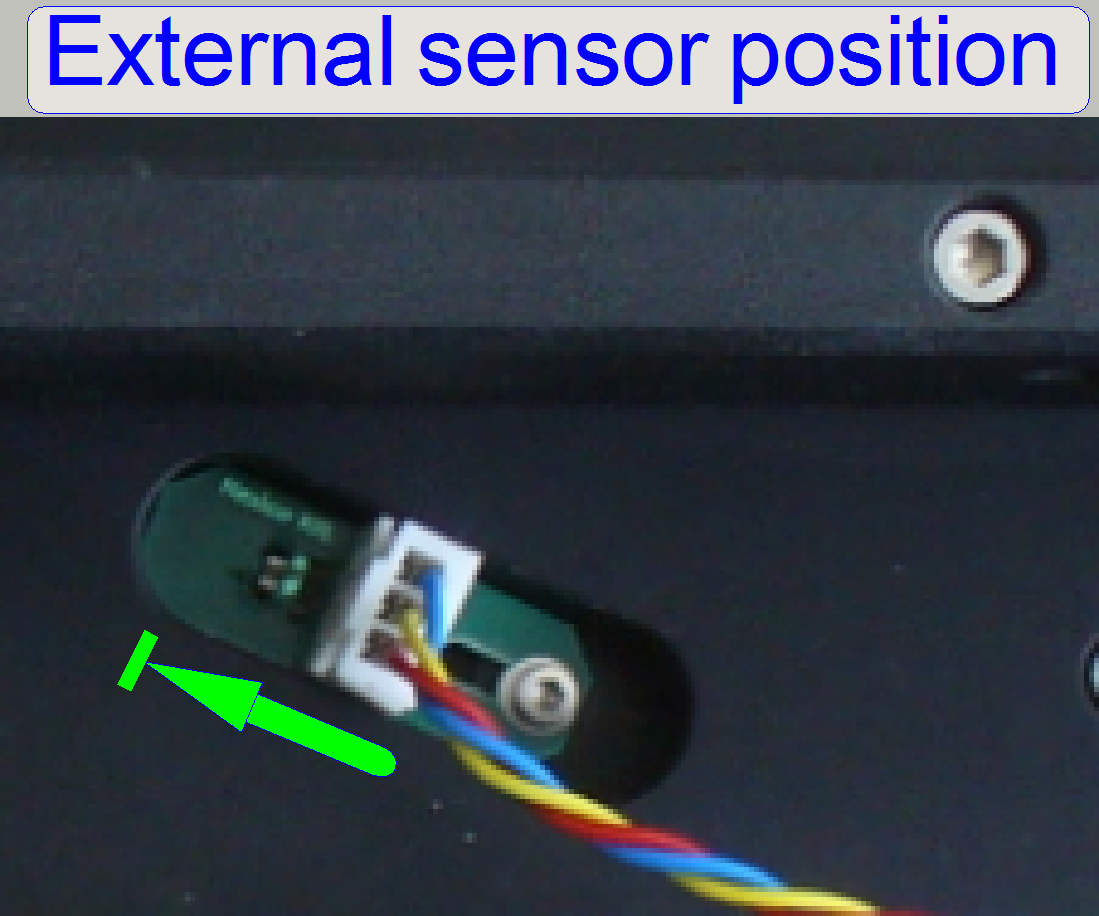 Loosen the
sensor mounting bolt and push the sensor to its end position as shown.
Loosen the
sensor mounting bolt and push the sensor to its end position as shown.- Tighten the sensor mounting bolt.
If the position of the home sensor was modified, check the
acting range.
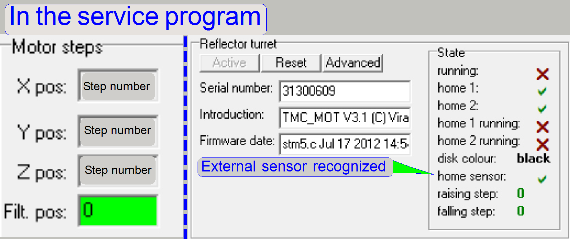 In the
service program, the state of the external sensor is shown by the state of
the item “Home sensor”.
In the
service program, the state of the external sensor is shown by the state of
the item “Home sensor”.- If the position Home1,2 is recognized and there are no steps lost,
the field “Filter position” in the table “Motor steps” is shown with zero
(0) on a green background.
- If the background is shown in red after pressing the buttons
Home1,2 press Home2 again until the background is shown in green or may be
the Home2 position can not be found.
Find the Home
position of the filter wheel
- This adjustment assumes that the tension of
the belt is checked, correct and will not be modified.
- The position
of the belt wheel’s clamp is correct.
The Home position of the mechanical drive is defined by
the active position of the sensor
Home1 inside the motor during the permanent magnet of the filter wheel
stays over the external sensor (the item “Home sensor is
activated).
1.
Start the service program
“SlideScannerService.exe” and switch active the section “reflector turret”.
2.
Rotate the filter wheel by hand or with
the service program until the filter position 6 stays in the filter insert
position.
3.
Move the filter wheel forward or backward
with a step number of 300 steps until the external sensor shows the active
state.
4.
To loosen the belt wheel clamp, may be the
belt wheel has to be rotated to the position, where the belt wheel
clamp’s fixing bolt can be reached by the 1.5 hex key wrench; count and
memorize the done steps.
5.
Loosen the belt
wheel clamp.
6.
Move the stepper motor the memorized
number of steps in opposite direction; the external sensor should show the
active state again.
7.
Prevent the filter wheel from movement by
hand and press the button Home1, perhaps 2 or 3 times.
8.
Rotate the belt wheel’s clamp until the
fixing bolt can be reached thru the drillings 1 or 2.
9.
During these actions only the belt wheel’s
clamp should be rotated and the motor axle should rotate about a half
revolution maximal; the filter wheel together with the belt wheel stays fixed,
they should not move!
10. Rotate
the belt wheel clamp into the appropriate position.
11. Release
the filter wheel and go forward or backward as necessary until the clamp fixing
bolt can be reached with the hex key wrench and tighten the belt wheel clamp.
12. Press
Home1, 2.
Check the home position of the mechanical drive
The home position is correct, if:
·
Press the buttons Home1 and Home2 for the
turret motor. The home position is found inside of 1 revolution of the filter
wheel.
·
The external
sensor acting range is correct.
·
The belt wheel
clamp’s fixing bolt can be reached if the mechanical drive stays in Home1,2
(recommended; not required).
Check or adjust the external sensor acting range
As
discussed above, the acting range of the external sensor is more 100 steps.
We assume, the Home
position of the filter wheel is found; the filter wheel can be set to Home2
in one revolution maximal.
 The position
of the belt wheel is found correctly if the number of steps in positive
and negative direction from the found Home1,2 position is nearly equal; a
difference of 50 steps can be accepted.
The position
of the belt wheel is found correctly if the number of steps in positive
and negative direction from the found Home1,2 position is nearly equal; a
difference of 50 steps can be accepted.
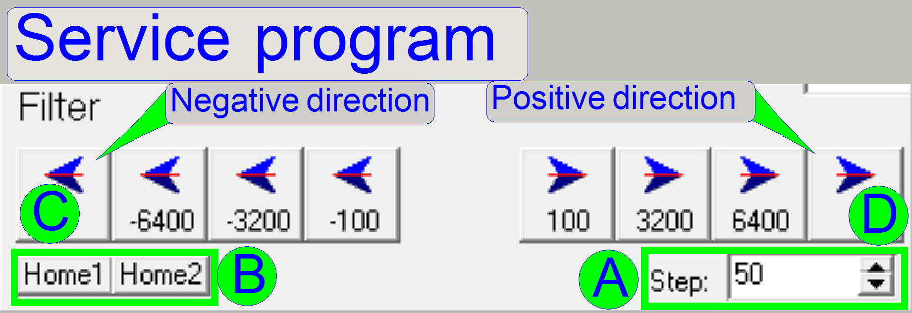
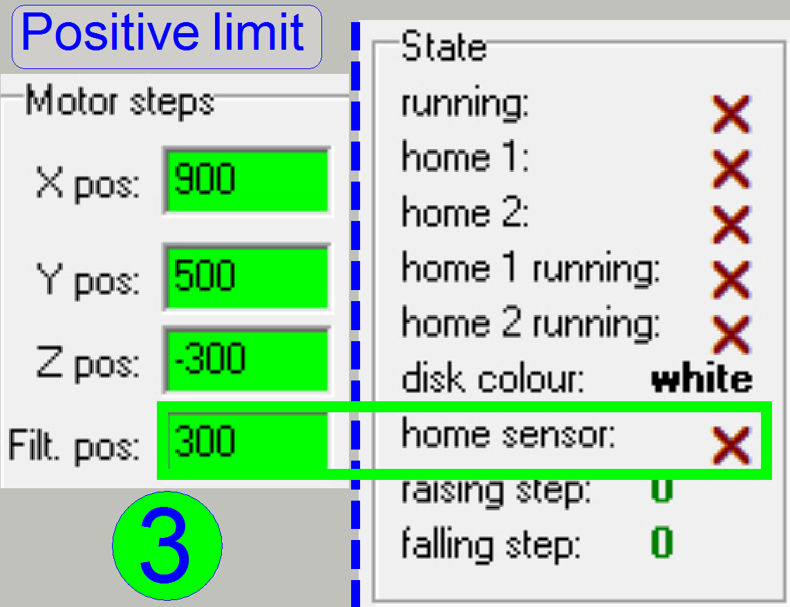
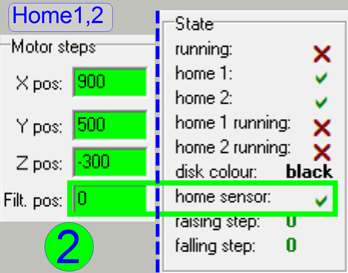
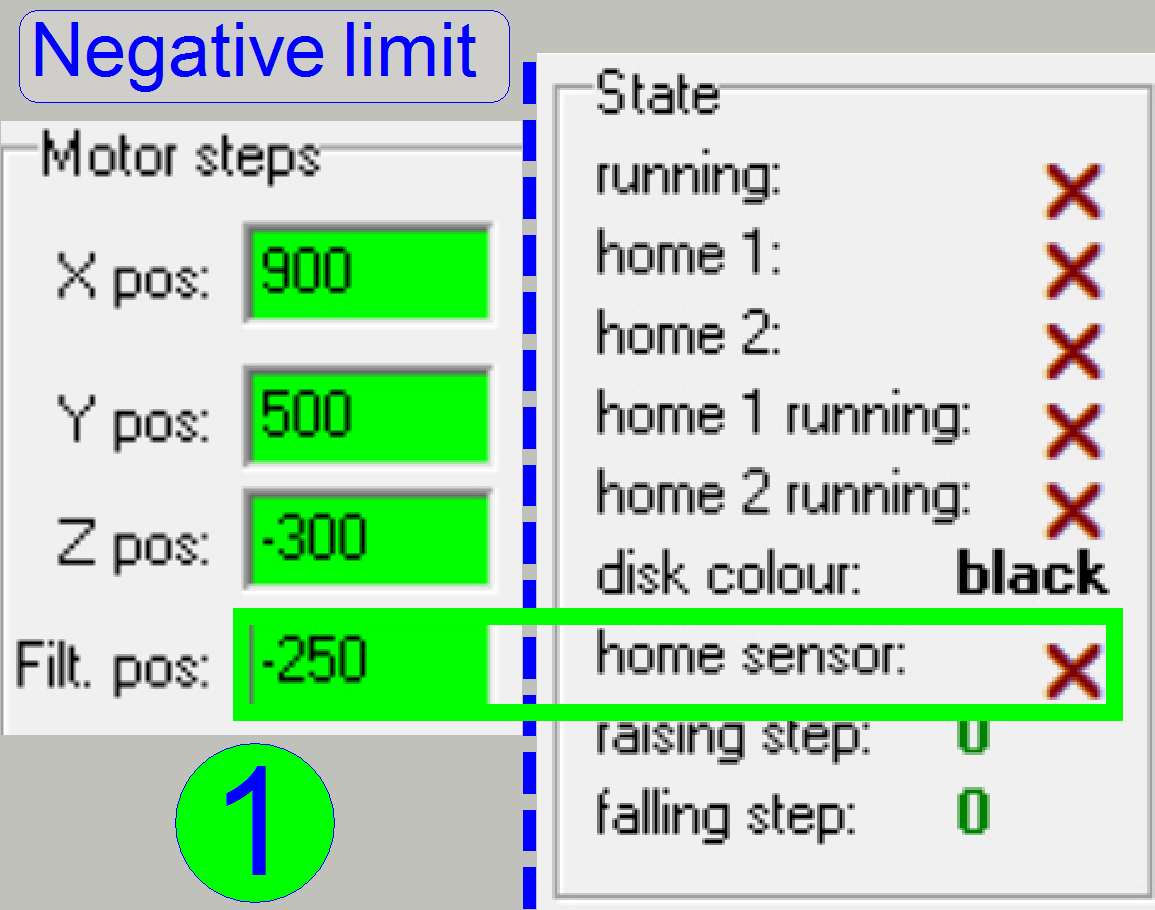
1.
Set the turret filter wheel with the
service program to the position Home1,2 (B), the result is shown in the figure
(2).
2.
Type in a step size of 50 steps (A).
3.
Move the filter wheel in positive
direction (D) until the “Home sensor” shows the inactive state first time;
figure (3).
4.
Memorize the number of steps.
5.
Set the turret filter wheel to the
position Home1,2 (B).
6.
Move the filter wheel in negative
direction (C) until the Home sensor” shows the inactive state first time;
figure (1).
7.
Compare the number of gone steps with the
memorized number of steps.
8.
If there are more then 50 steps
difference, adjust
the rotation position of the belt wheel more precise.
9.
Set the turret filter wheel with the
service program to the position Home1,2 (B), the result is shown in the figure
(2).
10. Check
the acting range again, repeat from step; figure (3.).
11. If the
belt wheel position was altered, “check or find the
first filter position” again.
Check or find
the 1st filter position
- This adjustment assumes that the belt tightness is adjusted
correctly.
- The
acting range of the external sensor is found; the Home1,2 position of
the filter wheel is correct.
To
find the first filter position
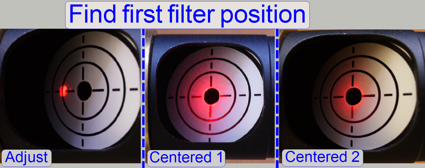 A. Mount
the autocollimator with the dovetail ring adapter to the fluorescent light input
connector and switch it on with the highest intensity.
A. Mount
the autocollimator with the dovetail ring adapter to the fluorescent light input
connector and switch it on with the highest intensity.
B. Press
Home 1 and Home 2.
C. After
the filter is inserted, bring the filter into the light path by pressing 5
times the button 3200 forward for the turret filter unit.
D. With
the 100 steps button go forward or backward until the LASER beam appears on the
scale.
E. Select
a step size of 10 steps and find the center of the scale by pressing the button
without step number.
F. By
reducing the intensity of the laser beam the reached position can be checked
better; see “Centered 2”.
G. If the
center is reached, subtract 16000 from the Filter step number shown for the
turret unit and use the found value to update the value of the parameter
“StartingMotorPosition” of the file “MicroscopeConfiguration.ini” section
[ReflectorTurret] and save the file.
H. Switch
off the autocollimator and dismount the dove tail ring adaptor.
Procedure to adjust the exciting path
 This adjustment
is done to reach the optimal exciting for the fluorescent FOV. The “Aperture
position” and the “Luminous field position” will be adjusted first to the
center of the beam. If the adjustment is optimal, the brightest part of the
light beam is used. With the tool “Aperture size” the diameter of the beam is
limited; this eliminates unwanted reflections, otherwise in a limited range it
has affect in brightness and therefore reflects to the cameras exposure time.
With the tool “Luminous field size” the diameter of the visible field of view
is defined. The adjustment should be done with the parts starting from the
light source in direction to the tissue.
This adjustment
is done to reach the optimal exciting for the fluorescent FOV. The “Aperture
position” and the “Luminous field position” will be adjusted first to the
center of the beam. If the adjustment is optimal, the brightest part of the
light beam is used. With the tool “Aperture size” the diameter of the beam is
limited; this eliminates unwanted reflections, otherwise in a limited range it
has affect in brightness and therefore reflects to the cameras exposure time.
With the tool “Luminous field size” the diameter of the visible field of view
is defined. The adjustment should be done with the parts starting from the
light source in direction to the tissue.
1. Connect the fluorescent
light source like „X-Cite® Series 120” or
equivalent to the reflector turret unit of the scanner and switch it on. For
user information and precautions of „X-Cite® Series 120” or
equivalent light sources please, refer to the users manual of the product you
are using.
2. Loosen
the fixing bolts of the positioning tools for the “Aperture” and the “Luminous
field”. For the other two tool bolts the fixing bolts are situated in the
opposite position, from below.
3. Loosen
the fixing for the “Aperture size” and the “Luminous field size”.
Aperture size and Luminous Field size tool with
fixing
 Before
you start to adjust the aperture position or the luminous field position, the fixing
of the “Aperture size” and “Luminous field size” tool respectively should be
loosened, otherwise it blocks the diaphragm movement, because the force of the
spring is not enough to move the iris. By removing the fixing, the appropriate
adjustment tool can be dismounted, if necessary.
Before
you start to adjust the aperture position or the luminous field position, the fixing
of the “Aperture size” and “Luminous field size” tool respectively should be
loosened, otherwise it blocks the diaphragm movement, because the force of the
spring is not enough to move the iris. By removing the fixing, the appropriate
adjustment tool can be dismounted, if necessary.
Fluorescent light and image
path
Precautions: Never look directly into the beam of the fluorescent
light source! The lamp emits also ultraviolet light with very high intensity.
To prevent your eyes from harm (damage) use always sun glasses with a high
filter factor of UV light if the fluorescent light source is switched on and
you are adjusting the beam even if the cover of the turret unit is removed. For
further precautions please, refer to the manual for the fluorescent light
source you are using!
Adjustment images
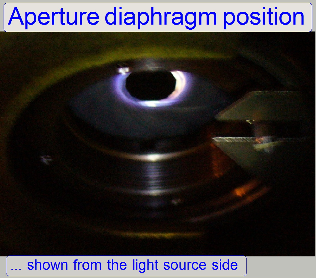 The aperture
diaphragm illuminated with the fluorescent light source.
The aperture
diaphragm illuminated with the fluorescent light source.
If the cover of the turret unit is removed, you can
see the beam on the iris, if this is not fully opened.
With the “Aperture positioning tools” bring the iris
into the centre of the beam. Check the position by varying the aperture size
tool. The center of the beam is reached, if the cut part of the beam is
illuminating the aperture iris evenly.
 To
adjust the aperture if the cover is mounted, you can use the bright field
illumination.
To
adjust the aperture if the cover is mounted, you can use the bright field
illumination.
Insert a sample, open the mechanical shutter, bring
the filter block into its position and switch on the bright field illumination.
· In the
P250 please use any kind of auxiliary illumination; the flash frequency of the
flash light source is too slow in the service program.
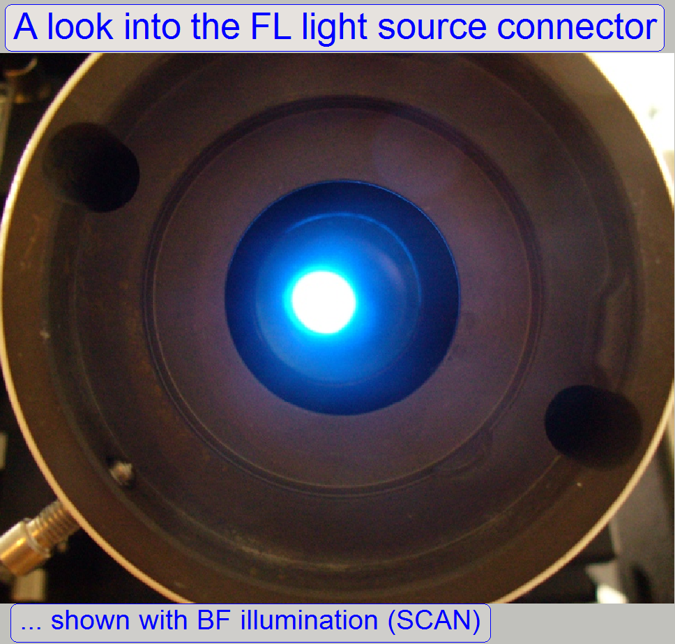
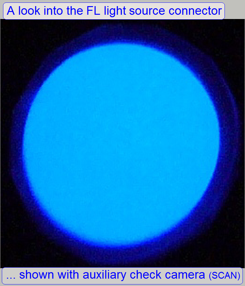
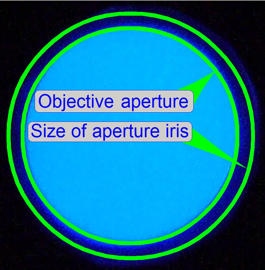 If you
are looking now into the “Fluorescent light source connector” and the luminous
field size is fully open, you can see the aperture of the objective and by
moving the aperture open or close tool you see the position of the aperture
iris. Adjust the iris position to the centre of the beam. By carefully varying
the size of the aperture, you can check the behavior of the iris. The movement
should be even in all directions related do the center of the beam.
If you
are looking now into the “Fluorescent light source connector” and the luminous
field size is fully open, you can see the aperture of the objective and by
moving the aperture open or close tool you see the position of the aperture
iris. Adjust the iris position to the centre of the beam. By carefully varying
the size of the aperture, you can check the behavior of the iris. The movement
should be even in all directions related do the center of the beam.
· Adjust
the aperture size so, that the aperture of the objective is evenly not cut.
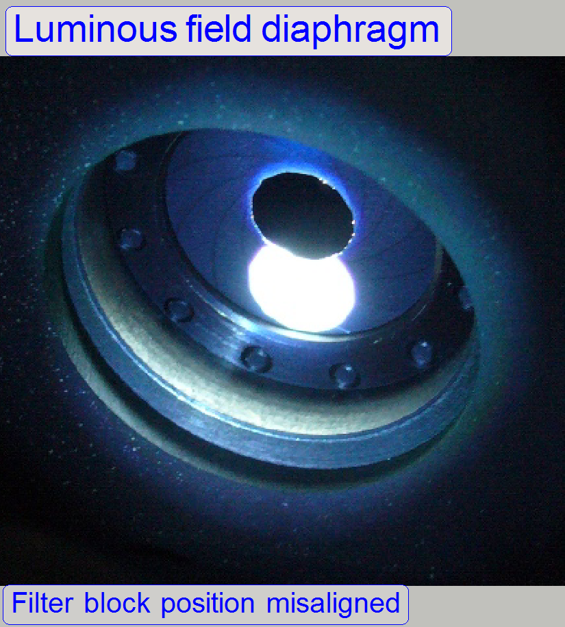 If the
cover is removed and you are looking onto the luminous field diaphragm on the mirror
side during adjustments, some times you can see that the reflected beam
(reflected by the filter block) does not meet the hole of the iris. In these
cases, may be the filter position is not correct (if the reflected spot is up
or down in relation to the iris and no autocollimator was used; see the image
on the right) and / or the position of the luminous field diaphragm is
incorrect (if the reflected spot is on the left or on the right in relation to
the iris).
If the
cover is removed and you are looking onto the luminous field diaphragm on the mirror
side during adjustments, some times you can see that the reflected beam
(reflected by the filter block) does not meet the hole of the iris. In these
cases, may be the filter position is not correct (if the reflected spot is up
or down in relation to the iris and no autocollimator was used; see the image
on the right) and / or the position of the luminous field diaphragm is
incorrect (if the reflected spot is on the left or on the right in relation to
the iris).
Always adjust the “first filter
position” before the adjustment of the diaphragm position will be done.
Check the position of the “Luminous field size
diaphragm” next.
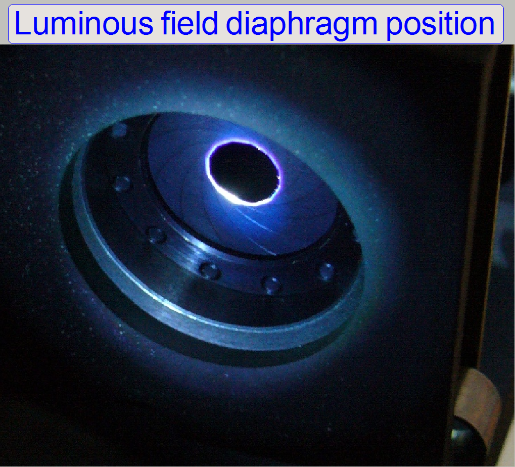 In
ideal cases you can see somewhat like this. The field size is in the center;
the filter block position is correct and the luminous field diaphragm is
centered; the reflected spot illuminates the edge of the iris hole evenly.
In
ideal cases you can see somewhat like this. The field size is in the center;
the filter block position is correct and the luminous field diaphragm is
centered; the reflected spot illuminates the edge of the iris hole evenly.
Adjustments
Before you start to adjust the aperture position or
the field position, the fixing of the “Aperture open or close” or “Luminous
field size open or close” tool respectively should be loosened, otherwise it
blocks the diaphragm movement, because the force of the spring is not enough to
move the iris.
· By
removing the fixing, the appropriate adjustment tool can be dismounted, if
necessary.
Check
or adjust the luminous field stop position
The check of the luminous field stop position is done
as described in the chapter “Check the filter block positions”, see later!
Prepare
the FOV for the adjustment
1.
With the program SlideScanner.exe produce a live view
with the option bright field scanning and the tab “Focus”. The tissue type can
be a “normal” tissue, it is not important that the tissue is not prepared for
fluorescent scanning (only the exposure time for the camera must be increased
more!).
2.
Use a well visible FOV where the corners
of the FOV have tissue also. This becomes important if we adjust the field
size. Adjust the focus position and memorize it.
3.
Kill the program “SlideScanner.exe” with
the task manager.
Prepare
the turret unit for the optics adjustment
4.
Start “SlideScannerService.exe” and “Low
Level Service”.
5.
Switch active the service part for
“Reflector turret” and “Focus” and press Home1 and Home2 for “Filter” and
“Focus”.
6.
Go to the first filter position; the value
of steps is given by the parameter “StartingMotor Position” of the file “MicroscopeConfiguration.ini”
section [ReflectorTurret]. In position 6 of the turret wheel insert the filter
block and go forward 5 positions. If all is correct, the numerical value in the
field “Filter” of the service program shows the sum of 32000 (5 times 6400
steps) + the value of the parameter “StartingMotorPosition”.
7.
In the “Focus” part of the service program
close the shutter; use the value of “FocusDeviceMax” in the file “Microscope
Configuration.ini” section [HardwareLimits].
8.
Open the aperture intensity and luminous
field size to maximum. Start the driver program for the marlin camera “AVT
SmartView,exe” and increase the shutter in the dialog “camera settings” until
the FOV becomes visible. In the menu “View” select the option “resize the
picture to the screen”. Now go backward with the focus stepper (do not press
Home1 or Home2!) from the focus position “FocusDeviceMax” to the memorized,
actual focus position. The FOV or a part of it should be seen in focus and the
mechanical shutter stays closed. Switch off the bright field illumination.
Adjust the shutter value for the camera and the focus position so, that the
illumination and the focus of the FOV is correct.
Adjust
the aperture position
9.
 Prepare
a sample for bright field illumination, insert the filter block and bring it in
the fluorescent scan position. If the fluorescent light source is disconnected,
you can see a light spot and the aperture iris in the light source connector.
The right aperture position is found if the beam is in the centre of the
aperture iris. The adjustment is done with the “aperture position” tools. You
can check it by observing the iris in relation to the objective aperture. By
carefully opening or closing the size of the aperture, you can check the
behavior of the iris. The movement should be evenly in all directions related
do the center of the beam. Tighten the fixing for the tool bolts.
Prepare
a sample for bright field illumination, insert the filter block and bring it in
the fluorescent scan position. If the fluorescent light source is disconnected,
you can see a light spot and the aperture iris in the light source connector.
The right aperture position is found if the beam is in the centre of the
aperture iris. The adjustment is done with the “aperture position” tools. You
can check it by observing the iris in relation to the objective aperture. By
carefully opening or closing the size of the aperture, you can check the
behavior of the iris. The movement should be evenly in all directions related
do the center of the beam. Tighten the fixing for the tool bolts.
10. Remember,
that the “Aperture intensity” tool can deform the result of the position; therefore,
during adjustment the intensity tool should be moved up and down from time to
time, at least, before the adjustment seems to be finished.
Adjust the luminous field position
11. 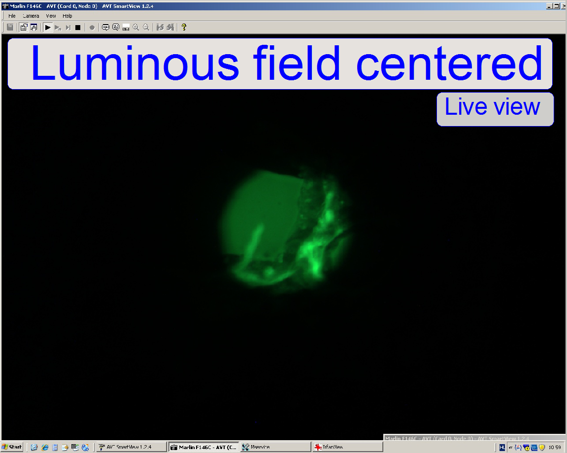 The right
“Luminous field position” is found if the beam is in the centre of the luminous
field iris. The adjustment is done with the “Luminous field position” tools. You can check
it by observing the iris pupil in relation to the beam. You can see the reflected
light of the beam from the condenser side. If the pupil border is evenly
illuminated by the beam, the adjustment is finished. You can see the tissue in
the centre of the screen, if the luminous field size is nearly closed.
The right
“Luminous field position” is found if the beam is in the centre of the luminous
field iris. The adjustment is done with the “Luminous field position” tools. You can check
it by observing the iris pupil in relation to the beam. You can see the reflected
light of the beam from the condenser side. If the pupil border is evenly
illuminated by the beam, the adjustment is finished. You can see the tissue in
the centre of the screen, if the luminous field size is nearly closed.
12. Now
open it carefully until the screen border is reached by the tissue and check
the luminous field position again. If the position is correct, the not
illuminated parts in the corners should be equal in size. A fine adjustment of
the luminous field position can be done now, if necessary. Tighten the fixing for the tool bolts.
13. Remember,
that the “Luminous field size” tool can deform the result of the field
position; therefore, during adjusting the field position, the field size tool
should be moved up / down from time to time, at least, before the adjustment
seems to be finished.
Check the filter block positions
·
 For
correct exciting of the FOV during fluorescent scan the insertion of the
filters in all used positions should be checked / adjusted.
For
correct exciting of the FOV during fluorescent scan the insertion of the
filters in all used positions should be checked / adjusted.
·
For this check use always the same filter
cube in each position of the filter wheel.
·
During this checks, the field size
diaphragm should be fully closed.
1. Start
the scan program “SlideScanner.exe”.
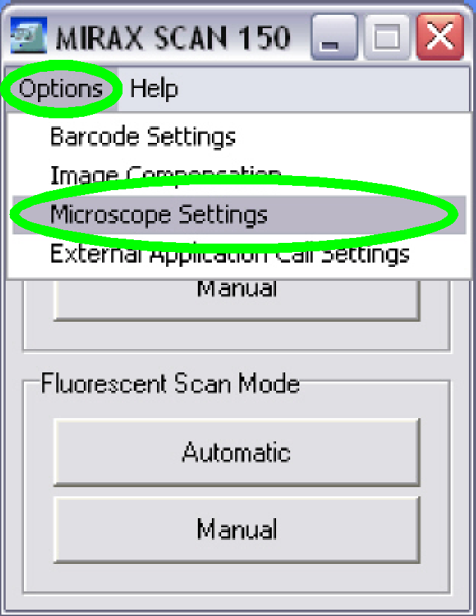
2. Select
“Microscope settings” in the menu “Options”.
3. Connect
and switch on the fluorescent light source.
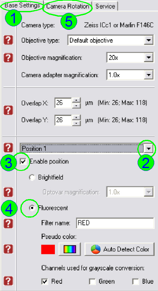
4. In the
tab “Base Settings” (1) select the desired filter position; e.g. “Position 1” (2).
5. Insert
the filter cube into the filter wheel, position 1.
6. Check
“Enable position” (3).
7. Set
the radio button “Fluorescent” (4).
8. Select
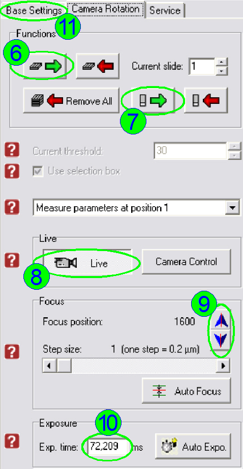
the tab “Camera Rotation” (5).
9. Load a
Magazine (6) and insert a slide with (any) tissue (7) (in the first filter
position only).
10. Check
“Live view” (8).
11. Find a
FOV inside the tissue and adjust the focus position (9) (in the first filter
position only).
12. Set
the “Auto Expo”sure time (10) (in the first filter position only).
13. Close
the tool “Field size”; only a small circle should be seen, nearly in the middle
of the red cross.
Remark: If the deviation
of the filter block axis in relation to the optical axis is very much, may be
you can not see the tissue (the screen is fully black). In such cases open the
luminous field size until the tissue becomes visible. Adjust the filter
position parts as described in “Reduce the
deviation from the center” then close the tool “Field size” again.
Repeat this procedure, until the center
of the red cross is met inside the tissue and the tool “Field size” is
fully closed.
14. Make a
screenshot with “Print Screen” and save it; e.g. with “Irfan view”; the file
name should be the filter position.
15. Switch off the live view, go
back with the tab “Base settings” (11) and remove the filter cube.
16. Select
the next filter position; e.g. “Position 2”,
insert the filter and repeat from step 6 logically.
17. Execute
the screenshots in all (desired) filter positions.
18. Analyze
the “Print screens”.
If the center of the
red cross can be found always inside the tissue, the filter cubes are inserted
well and no further adjustments are needed.
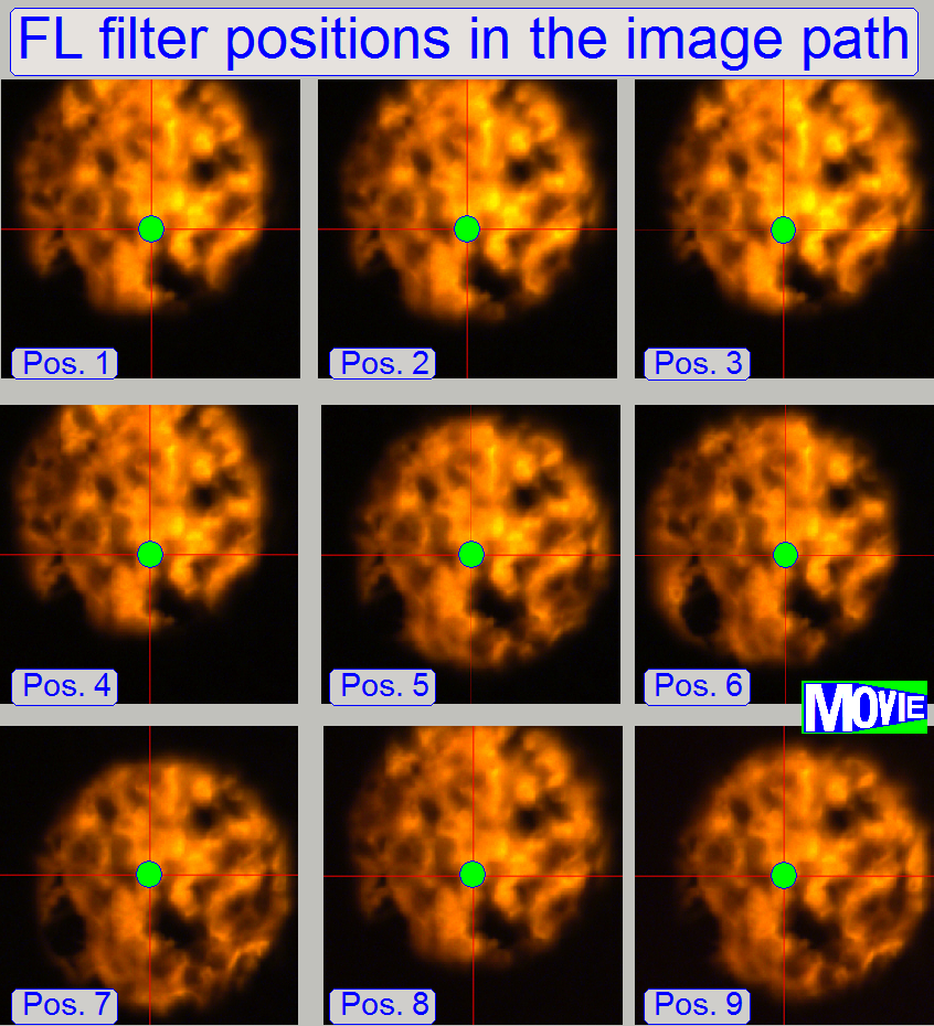
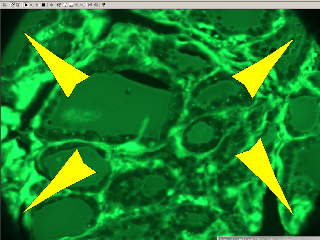
The screenshots
on the right show acceptable deviations from the center.
A real result of
the adjustment can be found in the slide show: “Filter positions”
The field size of
the luminous field is set to the minimum. Because the tissue is visible in the
center (shown with the red cross) of each filter position, the adjustment is
acceptable, but the position of the field diaphragm might be adjusted a bit
more precise.
Reduce the deviation from the
center
There are 4 possibilities to reduce the elongation of
the luminous field from the center of the red cross:
1.
Check the backlash of the
filter wheel; the tightness of the belt.
2.
Adjust the luminous
field stop position in the filter positions 2, 5 and 8, find the optimum
and check always the correct insertion of the filter block in the named
positions also.
3.
Check / adjust the value for the first filter
position more precise.
4.
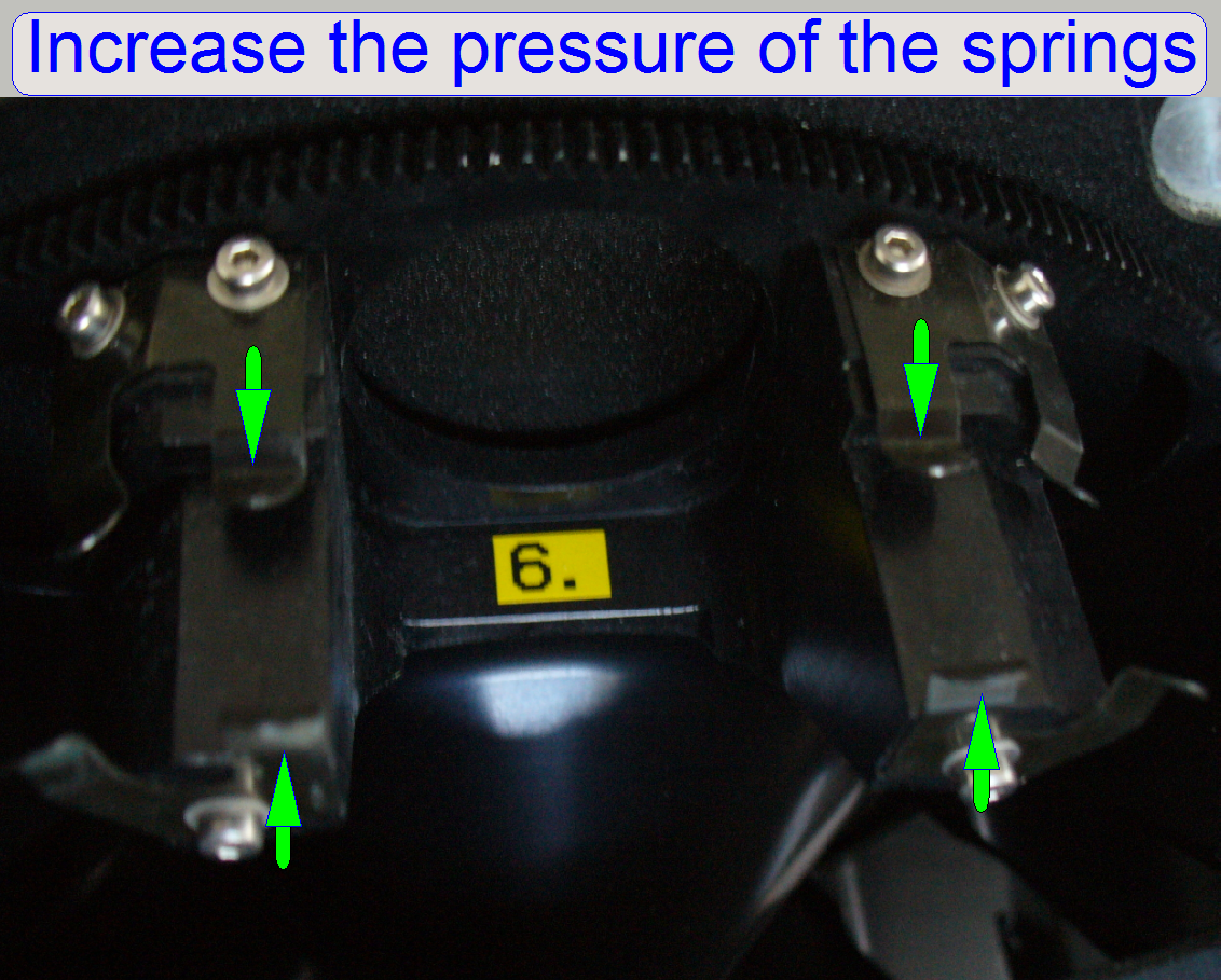 Increase
the pressure of the springs carefully for the filter block mounting in these
filter positions, where the deviation from the center is too much.
Increase
the pressure of the springs carefully for the filter block mounting in these
filter positions, where the deviation from the center is too much.
 Adjust
the luminous field size
Adjust
the luminous field size
·
Increase the luminous field size until the
entire screen is filled with tissue. Stop the adjustment and tighten the
luminous field size tool. For best results the adjustment should be done two or
three times.
·
Check the correct field size after all
filters are inserted; the seen FOV must not be cut.
Adjust
the aperture intensity
 Close fully
the aperture intensity tool then open it carefully until the brightness is
not increased more. Stop the adjustment and tighten the tool fixing. For
best results the adjustment should be done two or three times.
Close fully
the aperture intensity tool then open it carefully until the brightness is
not increased more. Stop the adjustment and tighten the tool fixing. For
best results the adjustment should be done two or three times.
Check
the mechanical shutter closed position
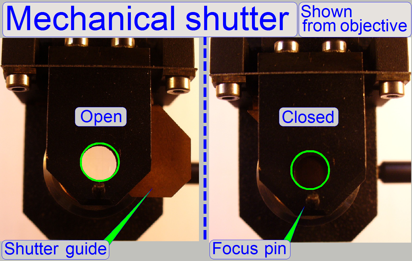 During a fluorescent
FOV is visible on the screen switch on and off the bright field
illumination several times with the service program. If the shutter is in
proper position the brightness of the view must not change.
During a fluorescent
FOV is visible on the screen switch on and off the bright field
illumination several times with the service program. If the shutter is in
proper position the brightness of the view must not change.
Parameters in the file
“MicroscopeConfiguration.ini”
[Version]
CurrentInifileVersion=1.9; actual
MicroscopeConfiguration.ini file version since MScan.exe version 1.9 or higher,
do not modify
[Microscope]
SerialNumber=xxxx; a
four digit number defines the serial number of the P250, so the file
MicroscopeConfiguration.ini is assigned to the hardware.
MicroscopeType=3DMic9; 3DMic9
means Pannoramic 250
ScanCameraType=; not
used
PreviewCameraType=CVrmc_m8_pPro; the preview camera
BarcodeReaderType=PreviewCamera
ReflectorTurretType=RT_3DH_10Pos_Belt; see also: P250_turret_unit
BrightfieldLightSourceType=FlashLight2010; see also: Brightfield light
source
BrightfieldLightSourceType=FlashLight2012; see also: “ND filter unit” and “Upgrade to the
software version 1.16”
ObjectiveChangerType=OC_2Pos; see also: Configure …
ObjectGuideXYZType=OGXYZ_FLASH3; see also: P250_X_Y_stage_unit
FlashUnitType=FlashUnit_Type2; see also: Flash light source
NDFilterType=NDType2; see
also: ND-filter unit
PreviewLightType=PreviewLightUnitType_Type2; see also: Preview illumination unit
PowerSwitchBoardType=PowerSwitchBoard_Type1; see also: Power
distribution & switch board
[HardwareLimits] The
number of steps is always defined without mechanical jamming
ReflectorTurretMin=-300; not
used in the belt driven version
ReflectorTurretMax=58700; not
used in the belt driven version
[ReflectorTurret]; at the
end of the file
StartingMotorPosition=-30;
here
named as “First filter position”.
MotorPositionDelta=3200; Number
of motor steps between two filter positions