Handling
the INI files
For
technicians!
 The following chapter contains information
about the *.ini-files with explanation of used parameters and their meaning.
The following chapter contains information
about the *.ini-files with explanation of used parameters and their meaning.
The sample, etalon file “MicroscopeConfiguration.ini”
is stored as “MicroscopeConfiguration.txt” containing all the parameters, used
in the software 1.18 and may be used as starting file for upgrading to the
appropriate software version.
Important
· The scanner specific parameter values of
the etalon ini-file in the sections [HardwareLimits],
[PreviewAndBarcodeScanning] and other sections should not be copied to the
ini-file of the scanner in front of you!!
· The etalon ini-files should be used only
to verify the existence of required parameters; values are mostly unique in
each scanner!
· Please make a security backup of the
existing ini-files before manipulating parameters and values!
·
If modifications are done in the file
“MicroscopeConfiguration.ini”, the scan software “SlideScanner.exe” has to be
started again; only so the modifications take effect (this is true for some
parts of the service program also).
If you working with the service program, please refer
also to “SlideScannerService”
Contents
Construction
of “MicroscopeConfiguration”
Sections
in the file “MicroscopeConfiguration.ini”
[WaterFeeder]; PCON
[Shutter]; PCON
As commonly known, the file “MicroscopeConfiguration.ini”
and the file “MicroscopeSettings.ini” contain scanner specific information and
are unique for each scanner.
Before the software version 1.9 these files were
named as “tdhmic_config.ini” and “tdhmic_settings.ini”.
Since the software version 1.9, the files are named
as “MicroscopeConfiguration.ini” and “MicroscopeSettings.ini”.
The file “MicroscopeConfiguration.ini”
contains hardware specific parameters and values concerning the scanner hardware;
these should be modified only during system integration or repair procedures by
a qualified technician!
The file “MicroscopeSettings.ini”
contains settings information concerning the used camera(s), installed
objective type(s) and magnification as well as implemented filters for
fluorescent scan mode. These values are updated during the saving procedure of
the dialogue “Microscope
settings”.
The original versions of the ini-files are stored in
the EEPROM of the Scanner’s USB controller also; please refer to “EEPROM”
· The parameter values of the file
“MicroscopeConfiguration.ini” are not collected in a dialogue, so the technician
has to patch the values by the use of a simple text editor, then the file has
to be saved as a file without formatting information; as a “txt only” type file
with the extension ".ini".
Information about the path of the appropriate
ini-file can be found in the chapter “Paths and locations”
Construction of the file
“MicroscopeConfiguration.ini”
The entire file is divided into sections; the
sections starting with the section name, and this is defined within brackets.
The length of the section, the section body, is defined until the next section
name is found.
[SectionName]
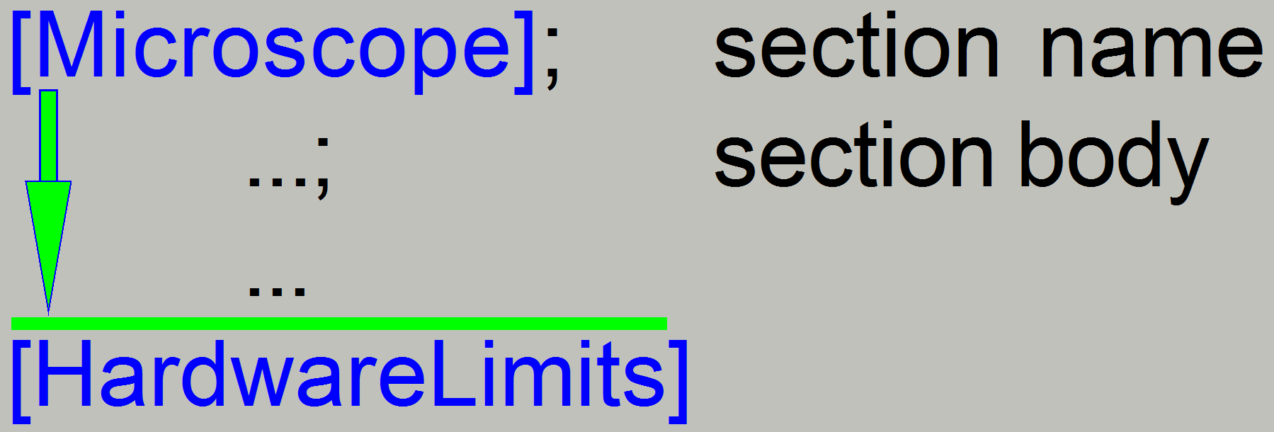 The sections are following each other
sequential in the file.
The sections are following each other
sequential in the file.
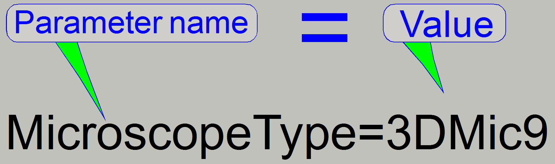
Inside the section body, the parameter value is found
by comparing the parameter name.
· A semicolon “;” behind the value is used
to define comment text in the appropriate line
· If a line starts with a semicolon “;” in
the first character position of the line, the entire line is comment text only.
This is often used to exclude parameters and values from the appropriate
section; so variants of the parameter value can be tested easily and quickly.
·  Each section contains specific parameter
names; the parameter names are unique in the entire file.
Each section contains specific parameter
names; the parameter names are unique in the entire file.
· The value, assigned to the parameter name,
is shown on the right side of the equal sign “=”.
· Negative values starting with a minus (-)
sign!
· Values related to the moving part of the
unit and defined outside the hardware limit are cut to the hardware limit by
the scan software!
Sections in the file
“MicroscopeConfiguration.ini”
 It contains information about the construction
of the ini-file; usually the slide scanner software version number is used
since the modification of the ini-file handling is done. This value defines how
to handle the ini-file.
It contains information about the construction
of the ini-file; usually the slide scanner software version number is used
since the modification of the ini-file handling is done. This value defines how
to handle the ini-file.
CurrentInifileVersion=1.8; the
construction is realized in the file “tdhmic_config.ini”
· If the section [Version] or
the parameter “CurrentInifileVersion=” does not exist, the file format is
handled like in the file “tdhmic_config.ini”
Because new parameters are implemented in
the software version 1.9 the construction of the ini-files was modified.
· To decide, how the ini-file
must be handled, the version number was increased.
CurrentInifileVersion=1.9
Since the software version 1.9, the content and the
structure of the files was modified.
The file “MicroscopeConfiguration.ini”
contains hardware specific parameters and values concerning the scanner; these
should be modified only during system integration or repair procedures by a
qualified technician!
The file “MicroscopeSettings.ini”
contains user specific settings concerning the used camera(s), installed
objective type(s) and magnification as well as implemented filters for
fluorescent scan mode. These values are updated during the saving procedure of
the dialogue “Microscope settings”; please see “Setup filters” for
example.
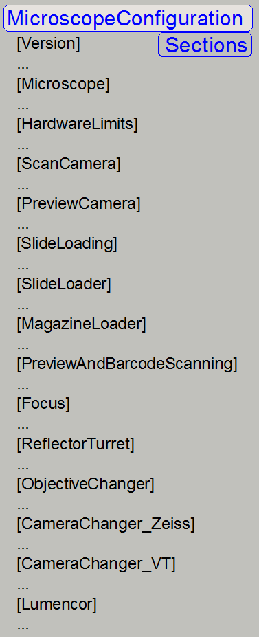
· An example of the sections since the
version 1.9 is shown on the right.
· Not required sections may be left out from
the sequence.
· The sequence of the sections is
unimportant and may vary in the ini-file of the scanner in front of you!
The section [Microscope] contains scanner specific
information concerning the implemented units and components.
An explanation about parameters and values can also
be found in the chapter “Configure …”
of the appropriate unit.
[Microscope]
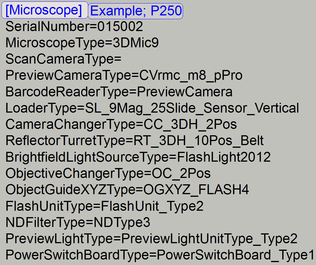 SerialNumber=xxxxxx; a
six digit number defines the serial number of the P250, so the file MicroscopeConfiguration.ini
is assigned to the hardware. The serial number should be equal (at least
partial) with the serial number on the label of the scanner. The serial number
may contain 15 alphanumerical characters.
SerialNumber=xxxxxx; a
six digit number defines the serial number of the P250, so the file MicroscopeConfiguration.ini
is assigned to the hardware. The serial number should be equal (at least
partial) with the serial number on the label of the scanner. The serial number
may contain 15 alphanumerical characters.
MicroscopeType=3DMic9; 3DMic9
means Pannoramic 250, see “ScannerType”
ScanCameraType=; not
used, defined in the “MicroscopeSettings.ini”
see
Scan
cameras
PreviewCameraType=CVrmc_m8_pPro; the
preview camera type; see Configure
preview unit
BarcodeReaderType=PreviewCamera; Barcode
reading is done by the preview camera
LoaderType=SL_9Mag_25Slide_Sensor_Vertical; Magazine unit type, see: Configure
magazine unit
CameraChangerType=CC_3DH_2Pos; see:
Configure
camera changer
ReflectorTurretType=RT_3DH_10Pos_Belt; see: Configure the turret
unit
;BrightfieldLightSourceType=FlashLight2010; see: Configure
brightfield light source
BrightfieldLightSourceType=FlashLight2012; see also: Configure ND filter unit
ObjectiveChangerType=OC_2Pos; see:
Configure objective changer
ObjectGuideXYZType=OGXYZ_FLASH3; see:
Configure
the X-Y-stage unit
 FlashUnitType=FlashUnit_Type2; see: Configure electronics components
NDFilterType=NDType2; see:
Configure ND-filter
unit
PreviewLightType=PreviewLightUnitType_Type2; see: Configure the preview unit
PowerSwitchBoardType=PowerSwitchBoard_Type1; see: Configure
electronics components
![]() “Focus unit OC” and “Configure the scanner”
“Focus unit OC” and “Configure the scanner”
· Not required parameters may be left out
from the parameter sequence
· Wrongly defined parameter names and values
will be ignored (as it would not be present) or causes a software error
· The sequence of the parameters is
unimportant so it may vary in the ini-file of the scanner in front of you!
Parameter options of the section
· Wrongly defined parameter
names and values will be ignored (as these would not be present) or causes a
software error
MikroscopeSubtype
MicroscopeSubtype=Confocal; modular
MicroscopeSubtype=SCS; modular
Preview Camera
PreviewCameraType=CVrmc_m8_pPro; S_M_D, P250, PCON,
Preview camera for delivered scanners since SW version 1.15
PreviewCameraType=DFK21F04; S_M_D type scanners; Preview camera
for delivered scanners until SW version 1.14
Following
software versions handling the DFK21F04 furthermore!
PreviewCameraSerialNumber=000XXX; SCS; because there are
several VR-magic cameras connected via USB to the same computer, the serial
number is used to distinguish the cameras.
PreviewCameraType =
CVrmc_m8_pPro_Double; DESK_II; the
extension "Double" is used to indicate that the capturing procedure
is done twice.
PreviewCameraType= CVrmc_m8_pPro; the camera VRMC-8+/C is
also recognized by the previously code for delivered scanners since SW version
Preview Illumination type
PreviewLightType=PreviewLightUnitType_Type4;
since SW version 1.20; P250 Flash;
Preview and barcode illumination connected to XYZND controller, SCAN_II
PreviewLightType=PreviewLightUnitType_Type3;
since SW version 1.20; S_M_D,
MIDI_OC; SCAN_OC;Preview and barcode illumination connected to DC-controller,
as usual in MIDI and DESK type scanners.
PreviewLightType=PreviewLightUnitType_Type2; P250 and Flash types; Backgrund and DF
Preview illumination present; BF and FL scan
PreviewLightType=PreviewLightUnitType_Type1; P250 and Flash types; DF preview
illumination removed; BF scan only
Reflector turret type
ReflectorTurretType=RT_None; any scanner without turret unit mounted;
BF scan only type scanners
ReflectorTurretType=RT_3DH_10Pos_Belt; P250, SCS; S_M_II
ReflectorTurretType=RT_3DH_10Pos_Gears; SCAN and
Camera Changer type
CameraChangerType=CC_None; MIDI_OC; SCAN_OC; PCON, SCS; S_M_D_II, any
scanner without motorized camera changer
CameraChangerType=CC_3DH_2Pos; P250, any scanner with motorized camera changer
mounted
CameraChangerType=CC_3DH_Fix1PosType1; since SW-version 1.18.2; 90° camera tube
present
Objective changer type
ObjectiveChangerType=OC_None; S_M_D type scanners
without motorized objective changer or parameter not used
ObjectiveChangerType=OC_2Pos; any scanner with
motorized objective changer
Loader type
LoaderType=SL_9Mag_25Slide_Sensor_Vertical; P250 and Flash types; the magnet
disc stops with the rising edge of the sensor
LoaderType =
SL_6Mag_25Slide_NoSensor_Vertical; SCAN;
the magnet disc stops with the falling edge of the sensor; 3Dmic6 and 3Dmic8
LoaderType =
SL_6Mag_25Slide_NoSensor_Vertical_2; SCAN
150, PSCAN, S_II the magnet disc stops with the rising edge of the sensor;
3Dmic8
LoaderType =
SL_1Mag_12Slide_Sensor_Horizontal;
LoaderType =
SL_1Mag_12Slide_Sensor_Horizontal2; PCON;
LoaderType =
SL_1Mag_12Slide_Sensor_Horizontal_SCS; special
tray for iSaCS; the transporter can reach the tray position 1 of the modular
LoaderType =
SL_1Slide_DoubleWide DESK_II,
single and double width slide
LoaderType =
SL_1Mag_12Slide_Sensor_Horizontal3; MIDI_II
Brightfield scan illumination type
BrightfieldLightSourceType=BLS_Halogen_5W; MIDI_OC; SCAN_OC; S_M_D type scanners
BrightfieldLightSourceType=FlashLight2012; P250 Flash types; BF scan with 40x
magnification possible
BrightfieldLightSourceType=FlashLight2010; P250; BF scan with 40x magnification
impossible
BrightfieldLightSourceType
= RGBLedLight; RGB illumination
unit, PCON, S_M_D_II
Power distribution and switch board type
PowerSwitchBoardType=PowerSwitchBoard_None; MIDI_OC; SCAN_OC; S_M_D type scanners
PowerSwitchBoardType=PowerSwitchBoard_Type1; P250 and Flash type scanners, iSaCS
Object guide type
ObjectGuideXYZType=OGXYZ_1; S_M_D; MIDI_OC;
SCAN_OC; 1.0mm slides; Step motor contains control electronics
ObjectGuideXYZType=OGXYZ_FLASH2; Y-stage=89600steps; 1.0mm slides;
step motor control realized in XYZND-controller
ObjectGuideXYZType=OGXYZ_FLASH3; P250, P250 Flash;
Y-stage=89600steps; XYZND-controller; slides 1.2mm
ObjectGuideXYZType=OGXYZ_FLASH4; Flash2; Stepper motor firmware upgraded
ObjectGuideXYZType =
OGXYZ_TypeDouble; D_II
ObjectGuideXYZType =
OGXYZ_1.2mm MIDI_II
Flash unit type
FlashUnitType=NoFlashUnit; MIDI_OC; SCAN_OC;
S_M_D type scanners
FlashUnitType=FlashUnit_Type2 P250; P250 Flash; P250 Flash2;
X-Y-Z-ND Flash-controller present
ND filter type
NDFilterType=ND_None; MIDI_OC;
SCAN_OC; S_M_D type scanners
NDFilterType=NDType3; Motor driver
firmware upgrade to reach the high scan speed in Flash3 type scanners, since
SW-version1.18.2
NDFilterType=NDType2; P250; P250
Flash;
Water
feeder
WaterFeederType =WF_None; PCON; water feeder not
present
WaterFeederType=WaterFeeder_Type1; PCON; water feeder present
Shutter
motor
ShutterMotorType=Shutter_Motor; PCON; Shutter motor present
ShutterMotorMin= 0
ShutterMotorMax= 300
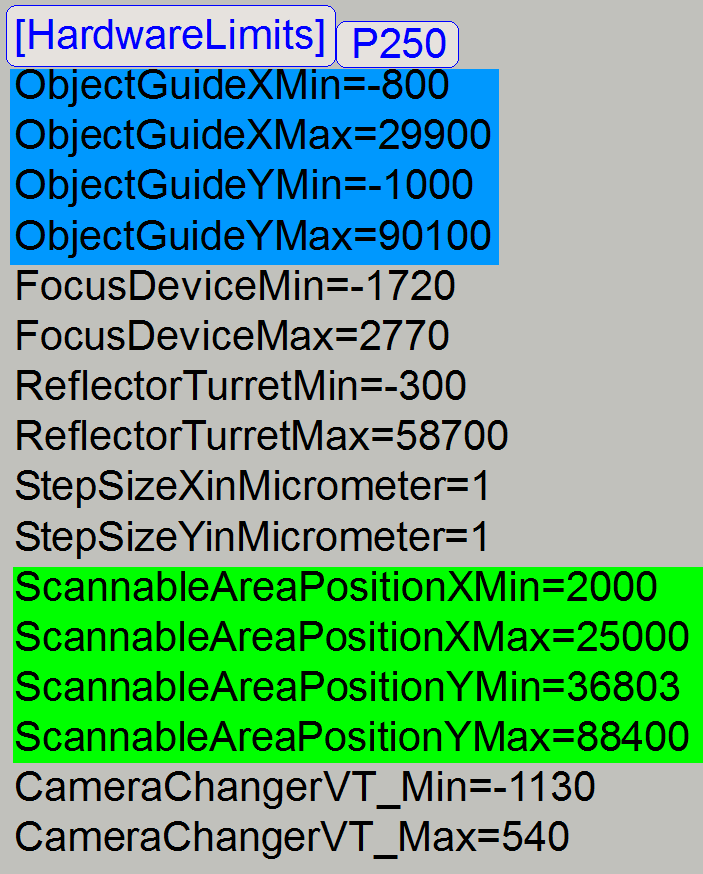
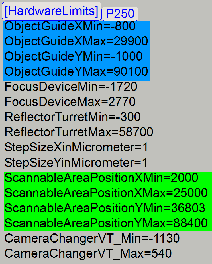 This section contains the hardware limits of
the moving parts of the units and related values, used in the scanner.
This section contains the hardware limits of
the moving parts of the units and related values, used in the scanner.
· Parameter value “min” is
always less than parameter value “max”!
ObjectGuideXMin=; ObjectGuideXMax=
These values defining the real movement
range of the moving part of the X-stage unit.
![]() “How to define hardware limits”, “X-direction_P250”
and “X-direction_S_M_D”
“How to define hardware limits”, “X-direction_P250”
and “X-direction_S_M_D”
ObjectGuideYMin=; ObjectGuideYMax=
These values defining the real movement
range of the moving part of the Y-stage unit.
![]() “How to define hardware limits”, “Y-direction_P250”
and “Y-direction_S_M_D”
“How to define hardware limits”, “Y-direction_P250”
and “Y-direction_S_M_D”
FocusDeviceMin=; FocusDeviceMax=
These values defining the real movement
range of the moving part of the Focus unit; the shutter off and shutter on
positions.
![]() “How to define hardware limits”, “Focus unit_P250”
and “Focus unit
_S_M_D”
“How to define hardware limits”, “Focus unit_P250”
and “Focus unit
_S_M_D”
ReflectorTurretMin=; ReflectorTurretMax=
These values defining the real movement
range of the Filter wheel in the reflector turret unit (used in the gear driven
version only).
![]() “How to define hardware limits”, “RTU_P250”
and “RTU_S_M”
“How to define hardware limits”, “RTU_P250”
and “RTU_S_M”
StepSizeXinMicrometer=1; StepSizeYinMicrometer=1; please do not modify
Movement accuracy of the mechanical drive
in X and Y-direction
· These values are constant in all scanner
types.
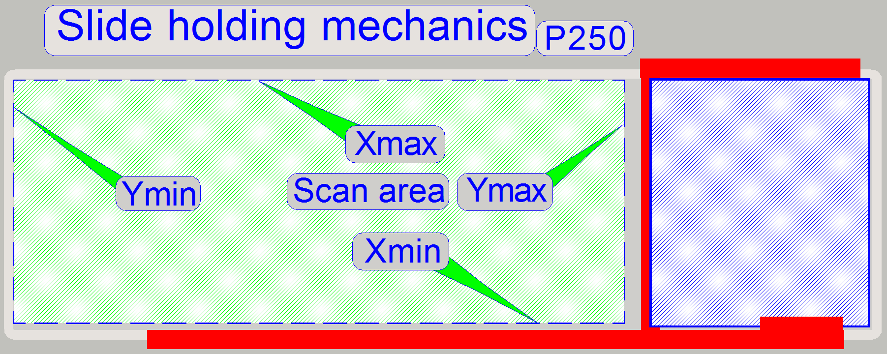
ScannableAreaPositionXMin=; ScannableAreaPositionXMax=
ScannableAreaPositionYMin=; ScannableAreaPositionYMax=
· The scan area is defined just before the
focus pin or the objective touches the specimen holder mechanics of the
scanner.
· The value of the parameter
“ScannableAreaPositionYMin=” will be modified as a result of the preview
calibration procedure.
Detailed information about the scan area
of the appropriate scanner can be found in the chapter:
Physical construction of the specimen
holder “PCON”, “P250”, “SCAN”, “MIDI” and “DESK”
Define
the scan area “PCON”, “P250”, “S_M_D”
Further parameters can be found in the
file “MicroscopeConfiguration.ini” of the PCON,
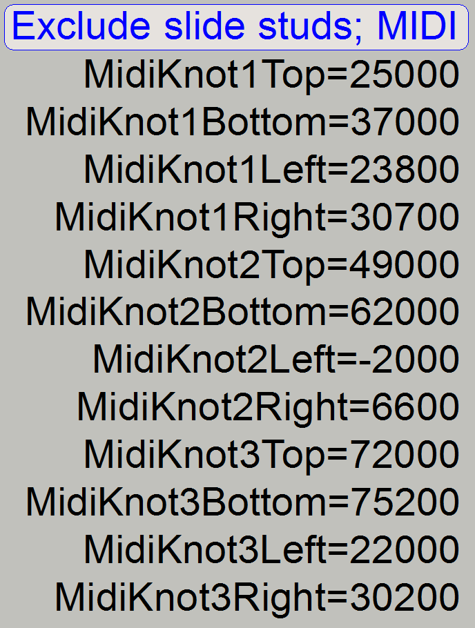
· The area of the slide stud is cut out
explicitly from the scan area of the slide; since the software version 1.16 and higher.
Further information can be found in the chapters:
![]() Scan area
and specimen holder “PCON”, “PMIDI”
and “PDESK”
Scan area
and specimen holder “PCON”, “PMIDI”
and “PDESK”
·  Values on the right are for demonstration only!
Remark
· Values, outside the defined hardware
limits are cut to the hardware limit by the scan software!
MidiTrayMoverMin=; MidiTrayMoverMax=
The movement range of the tray conveyor
unit is defined with these parameters.
More information about the values can be
found in the chapter:
![]() “Tray- and slide loading”, “Check the physical limits of the tray loader”
“Tray- and slide loading”, “Check the physical limits of the tray loader”
MidiFeederArmMin=; MidiFeederArmMax=
The movement range of the slide loader is
defined with these parameters.
More information about the values can be
found in the chapter:
![]() “Tray- and slide loading”, Define “MidiFeederArmMin”
and “MidiFeederArmMax”
“Tray- and slide loading”, Define “MidiFeederArmMin”
and “MidiFeederArmMax”
CameraChangerVT_Min=; CameraChangerVT_Max=
These values defining the real movement
range of the camera changer stepper motor’s rotor.
· The sum of both values must exceed the
rotation angle of 180º = 1600rotor steps!
![]() “How to define hardware limits”, “Camera
changer unit” and “Find the
hardware limits”
“How to define hardware limits”, “Camera
changer unit” and “Find the
hardware limits”
PCON, SCAN,
ObjectGuideXYTimeDelayBeforeImageAcquisition=30
This value defines a “pause time” in [ms] between
reaching the desired slide position of the X-Y-stage unit and start of FOV
capturing.
The value is used in the “start-stop” scan mode only
and should help to eliminate vibrations.
· The recommended value is 30ms
· A value of “
· Higher values decreasing the scan speed
(drastically)!
 This section contains initial parameter
values for the scan camera; since the software version 1.12 these values are
handled by the scan program SlideScanner.exe; do not modify.
This section contains initial parameter
values for the scan camera; since the software version 1.12 these values are
handled by the scan program SlideScanner.exe; do not modify.
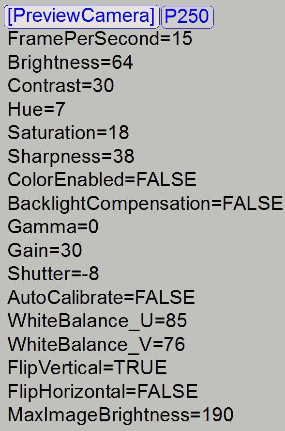 This section contains initial parameter
values for the preview camera; since the software version 1.12 these values are
handled by the scan program SlideScanner.exe; do not modify.
This section contains initial parameter
values for the preview camera; since the software version 1.12 these values are
handled by the scan program SlideScanner.exe; do not modify.

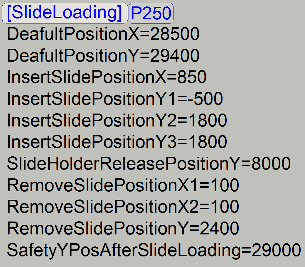
![]() PCON: “Tray_slide_loading”
PCON: “Tray_slide_loading”
P250: “Magazine unit; Slide handling”
SCAN: “Magazine
unit; Slide handling”
DESK: “Define
slide insert and remove parameters”
· Please do not modify these values!
· Please do not modify these values!
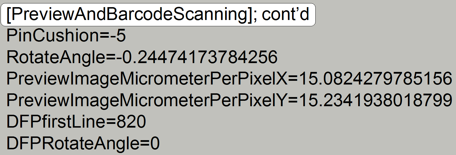
Section
[PreviewAndBarcodeScanning]
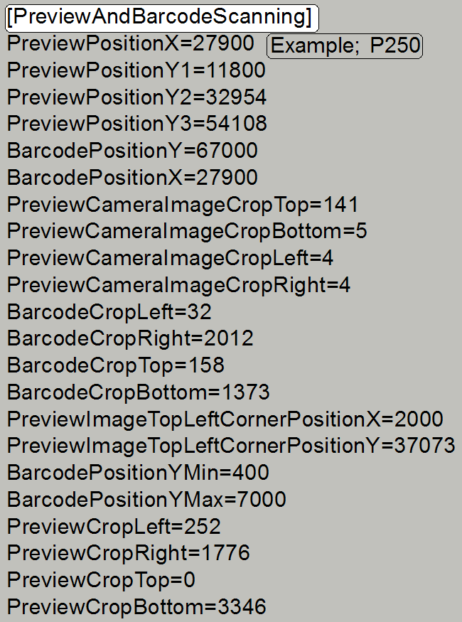
![]() “Field of view and Preview Area”
“Field of view and Preview Area”
S_M_D: “Preview
unit”
P250: “Preview
unit” and “Darkfield
preview”
PCON: “Preview”
and “Darkfield
preview”
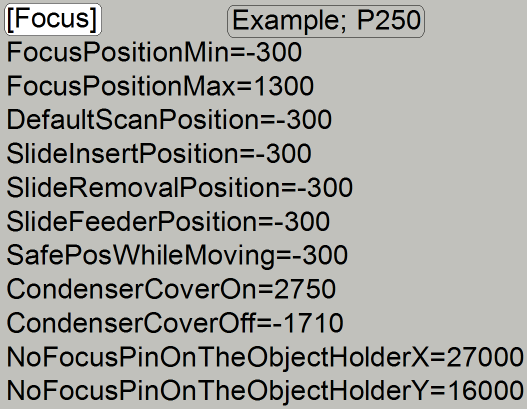 CondenserCoverOn= CondenserCoverOff=
![]() S_M_D: “Focus unit” “Find the hardware limits”
S_M_D: “Focus unit” “Find the hardware limits”
P250: “Objective changer” “Find the hardware limits”
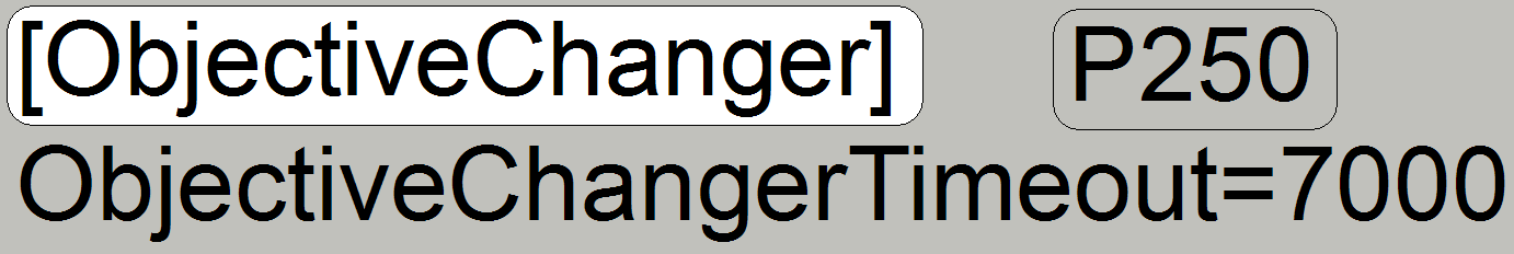
FocusTimeDelayBeforeImageAcquisition=40
Since the SW-version 1.17 defines this value a “pause
time” in [ms] between reaching the desired slide position of the X-Y-stage unit
and start of FOV focusing.
· The recommended value is 40ms
· A value of “
· Higher values decreasing the scan speed!
![]() “FocusDeviceMin=;
FocusDeviceMax=”
“FocusDeviceMin=;
FocusDeviceMax=”
· Please do not modify not explained parameter values!
![]()
 PCON: “Objective changer” “Find the hardware
limits”
PCON: “Objective changer” “Find the hardware
limits”
StartingMotorPosition=
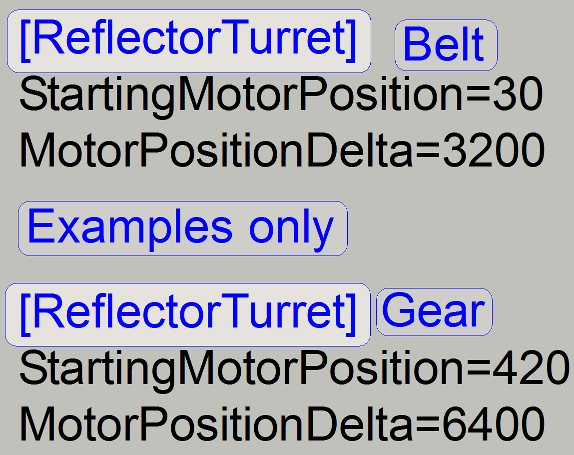
· Defines the correct filter position in
[motor steps] related to the illumination and image path.
· With this value, a deviation to the found
position of Home1,2 is defined, so the next or previous filter position will
fit exactly the image path also.
![]() S_M: “Find the
first filter position”
S_M: “Find the
first filter position”
P250: “Find the first
filter position”
MotorPositionDelta= Do not modify!
· Defines the distance between two filter
positions in [motor steps] related to the illumination and image path.
![]() S_M: ”Drive and limits”
S_M: ”Drive and limits”
P250: “Principle of
belt drive”
· Please do not modify these values!
 The unit is not implemented
· Please do not modify these values!
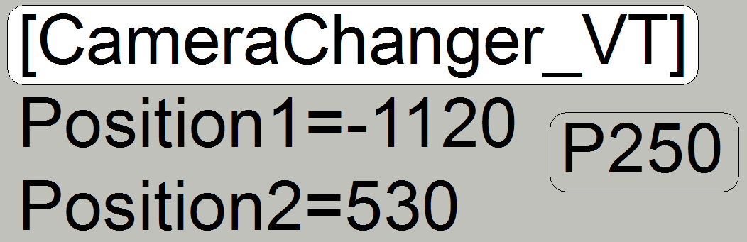 Position1= Position2=
· These parameters defining the mirror working position
in the camera position 1 and 2

![]() “Lumencor SPECTRA light
engine” and “Check and update the USB port
address”
“Lumencor SPECTRA light
engine” and “Check and update the USB port
address”
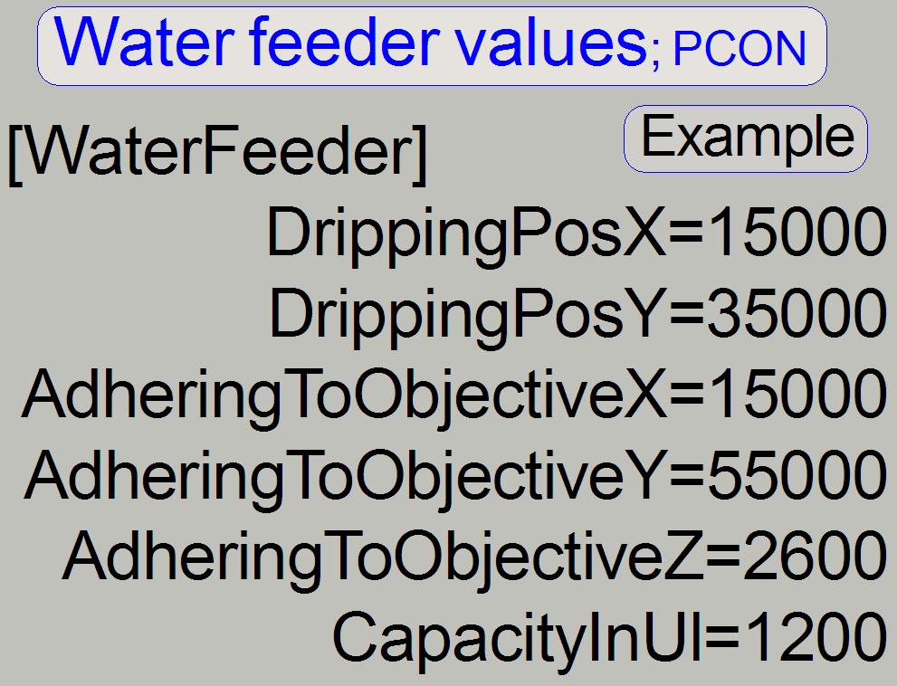 Used in PCON only
· Values for information only!
[WaterFeeder]
DrippingPosX=15000
DrippingPosY=35000
AdheringToObjectiveX=15000
AdheringToObjectiveY=55000
CapacityInUl=1200
![]() “Immersion liquid feeder_control” and “Immersion
Liquid Feeder_optics”
“Immersion liquid feeder_control” and “Immersion
Liquid Feeder_optics”
Used in PCON only
· Values for information only!
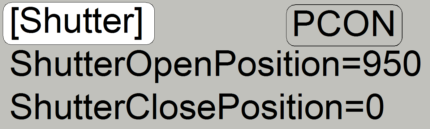
Please refer to the chapter “Shutter mechanics” and “Mechanical shutter”
Section
[Confocal]
ConfocalCalibationFilterPosition
= 1; During Start-up the Aurox
unit will be calibrated in the named filter cube position
Possible values are 1 or 2 or 3
ShutterMotorMin= 0
ShutterMotorMax= 300
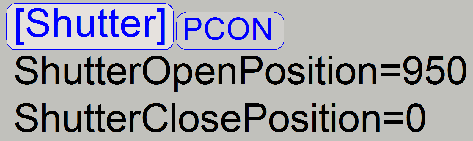
[Shutter]
ShutterOpenPosition=0
ShutterClosePosition= 200
· The etalon ini-files got the extension
“.txt” to avoid an unwanted overwrite of the original ini-file!
· Use these ini-files to check the existence of
parameter names in the appropriate sections of your MicroscopeConfiguration.ini
file.
· Open the file with “NotePad”
· The values, shown in the etalon ini-files
are for information only; please don’t use these without checks!
|
Scanner |
MicroscopeType |
Remark |
Download |
||
|
|
|||||
|
PCON |
Subtype=Confocal |
|
|||
|
P250 |
P250; and Flash types |
|
|||
|
PSCAN |
Without objective changer |
|
|||
|
PSCAN_OC |
SCAN modular; with OC |
|
|||
|
PMIDI |
Without objective changer |
|
|||
|
PMIDI_OC |
|
|
|||
|
DESK |
|
|
|||
|
SCAN_II |
3DMic11 |
|
|
||
|
MIDI_II |
3DMic10 |
|
|
||
|
DESK_II |
|
|
|||
|
|
|
|
|
||