FOV and Preview Area
For experienced technicians and beginners
The following chapter shows the preview image path, captured with the
preview camera and the image path of the Field Of View, captured by the scan camera.
Mainly the construction, proportions and relations of the optical paths to each
other are discussed and calculations are performed in relation to different
sensor and pixel sizes of the preview and the scan camera. These calculations
are performed by the preview calibration program and resulting values are used
during the preview creation process of “SlideScanner.exe”.
Contents
Optical path and Field Of
View
Influence of the camera adapter
Pixel
position and corrections
· The following
procedures are done by software, automatically, but in some situations the
shown information may help to understand processes.
The slide dimensions are defined as:
Width (X): 25.00 to 26.00mm
Length (Y): 75.00 to 76.00mm
 Pannoramic
scanners including always a preview unit and a scanner unit to create a virtual
tissue from the sample, situated on the slide.
Pannoramic
scanners including always a preview unit and a scanner unit to create a virtual
tissue from the sample, situated on the slide.
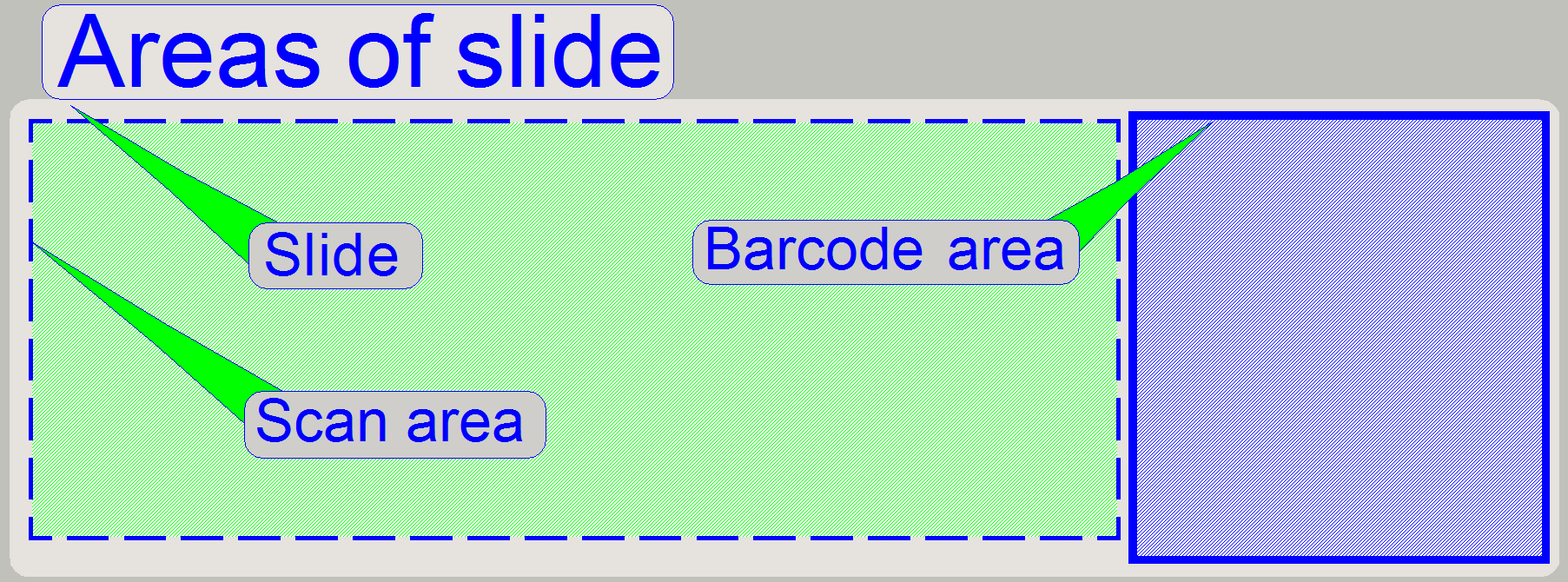
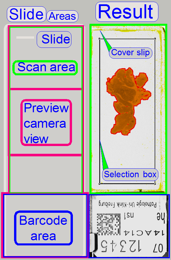
· The entire slide
is principally divided into 2 areas, the scan area where the sample is expected
to be and the barcode area, containing information about the tissue.
The made preview is shown in the preview window of Slide Scanner and it
shows the entire content of the scan area, so the user is able to select the
tissue, parts of the tissue (if the tissue is large) or only small areas of interest.
· The preview camera
captures the barcode area also during the preview creation process and the
taken image is transferred to the barcode analyzing and decoding software
module.
· In aspects of
hardware, the main difference between both areas is that any part of the scan
area may be seen by the scan camera also while the barcode area can only be
seen by the preview camera.
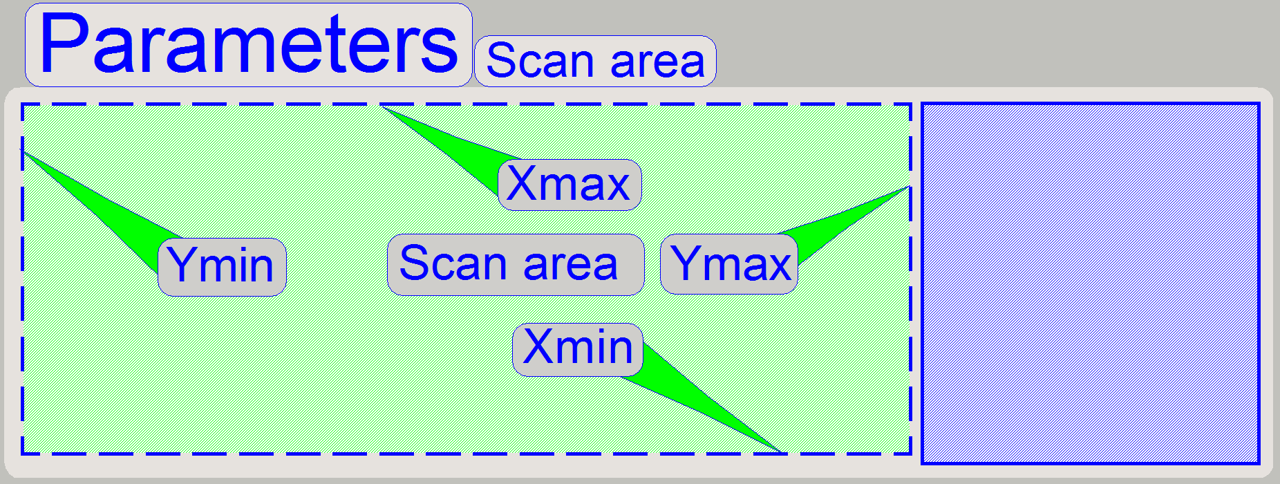 The scan area
(shown for SCAN and P250), defined by the values of “Scan area” X-min, X-max,
Y-min and Y-max differ in each scanner type and in scanners of the same type
also, but the parameters are named in each scanner type as shown.
The scan area
(shown for SCAN and P250), defined by the values of “Scan area” X-min, X-max,
Y-min and Y-max differ in each scanner type and in scanners of the same type
also, but the parameters are named in each scanner type as shown.
· The scan area on
the slide is ~24.5mm (X) x ~54.5mm (Y) (SCAN and P250); it depends highly on
the scanner type and the slide holding mechanics.
· In the file
“MicroscopeConfiguration.ini” the parameters of “Scan area” are named as
“ScannableArea” and found in the section [HardwareLimits].
More information can be found in the chapter “Specimen holder” of “P250”, “SCAN”, “MIDI” and “DESK”.
See also: “Areas of slide” “S_M_D” and “P250”
 In DESK and
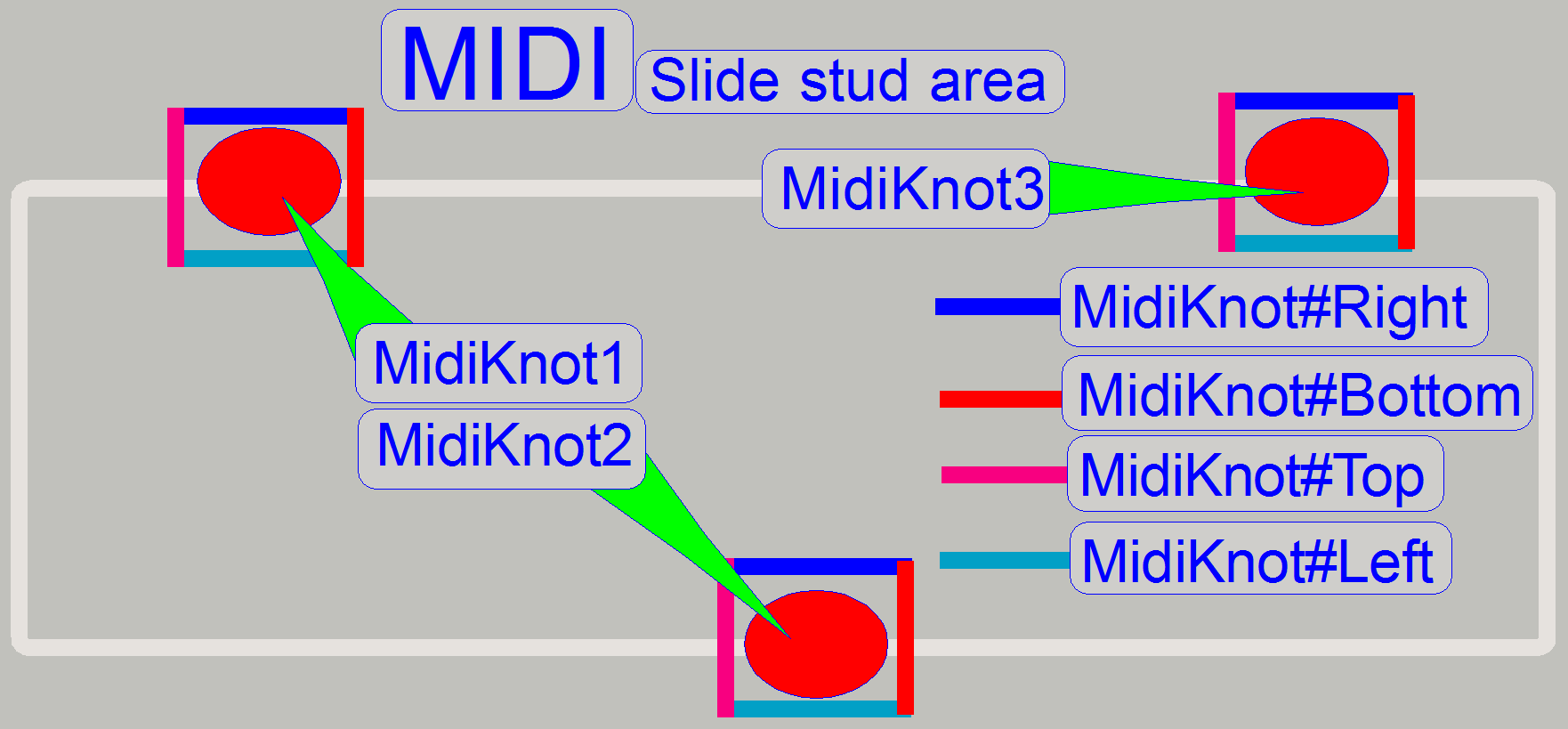
More information can be found in the chapter “Slide stud area” “MIDI” and “DESK”
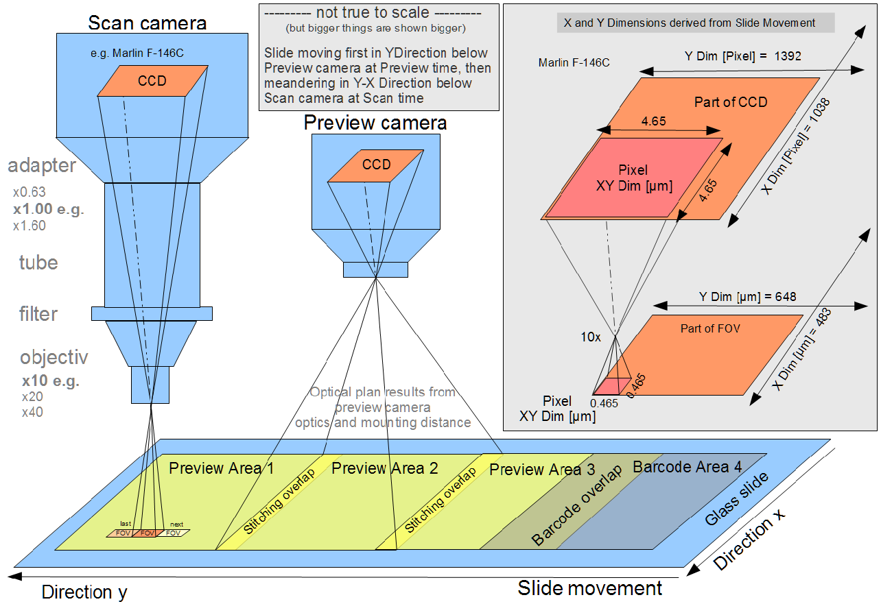
· The task of the
preview image path is done with the preview camera and its own preview
objective; while the path of the scan image is handled by the scan objective, the
camera adapter and the scan (main) camera.
· Both optical paths
are separated from each other and are in physical distance to each other.
· The arrangement of
the preview camera’s optical path works correctly like a common known digital
camera.
· The preview camera
creates a view of a slide part by
reducing the seen area to the size of the preview camera’s sensor.
· The arrangement of
the scan camera’s optical path works inversely in relation to a common known
digital camera.
· The image path of
the scan camera will enlarge
a very small area on the slide, the Field Of View (FOV) to the size of the
sensor.
· This means, the construction of the
image path of both cameras is inverse to each other!
By moving the slide over the scan objective’s pupil, the tissue,
situated on the scan area of the slide, will be scanned.
The scanned fields of view are rotated, cut and stitched by the
“SlideScanner.exe” and then, the virtual tissue or “Virtual Slide” can be
analyzed by the help of the Slide Viewer.
Remark
To
avoid confusion,
· we are not using
the term FOV (Field Of View) for the preview camera, use the term “Preview
camera view” instead!
· The slide area, seen
with the scan camera will always be named as “FOV”!
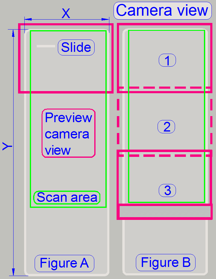 By moving the
slide over the view of the preview camera, only a part of the slide will be
seen (figure A).
By moving the
slide over the view of the preview camera, only a part of the slide will be
seen (figure A).
The distance and orientation of the camera, as well as the preview objective
magnification was chosen so, that the entire X-dimension can be seen, and a bit
more, so stitching becomes possible.
Because the scan area in Y-direction is much larger than the vertical view
of the preview camera, the entire preview image will be captured in 3 sections
(3 images; figure B).
· The overlapping of
the images is required for stitching!
The 3rd capturing of the scan area is much more than required; so the
not required part of the image will be cut at the end of the preview creation
process.
· The preview camera
makes a fourth image also; its content is the entire barcode area.
 The three images,
made by the preview camera view will be rotated, stitched and finally cut to
the dimensions of the Scan Area by software.
The three images,
made by the preview camera view will be rotated, stitched and finally cut to
the dimensions of the Scan Area by software.
· By correcting each
preview image by the preview camera rotation angle, the images are rotated
exactly horizontal.
· By fitting
(stitching) the images exactly to each other, no gaps are visible or
overlapping of the images will not occur.
· By cutting the
assembled images to the size of the Scan Area of the slide, the preview
capturing process is finished and the content of the Scan Area is shown in the
preview window of the program “SlideScanner.exe”.
The barcode area itself is captured by 1 image of the preview
camera.
· The barcode area
will be rotated by the camera rotation angle; the image is rotated exactly
horizontal.
· The X-dimension
will be cut, but it is a bit larger than the X-dimension of the Scan Area (its
limit is the widest possible slide dimension X).
· The Y-dimension is
cut only by the deviation from the horizontal direction (defined by the
rotation angle of the camera), to keep the barcode area as large as possible.
· The barcode image is not stitched to the Scan Area; it will be shown
in a separate “Barcode window” instead!
· During execution
of the preview calibration procedure steps, required values for the position
and size of the captured images, rotating angle of the preview camera view and
stitching values are defined.
· Accordingly
parameters and values are collected and found in the section
[PreviewAndBarcodeScanning] of the file ‘MicroscopeConfiguration.ini”.
Brightfield illuminated
preview; double width slide
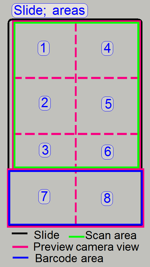
Because the slide is double in width, the preview
images are also made twice.
The advantage of this is, that the mechanics and
optics modifications are minimized.
The images are taken as shown with numbers.
·
In practice we can say, the image
capturing process of the single width slide preview is done twice.
Define
sample dilation
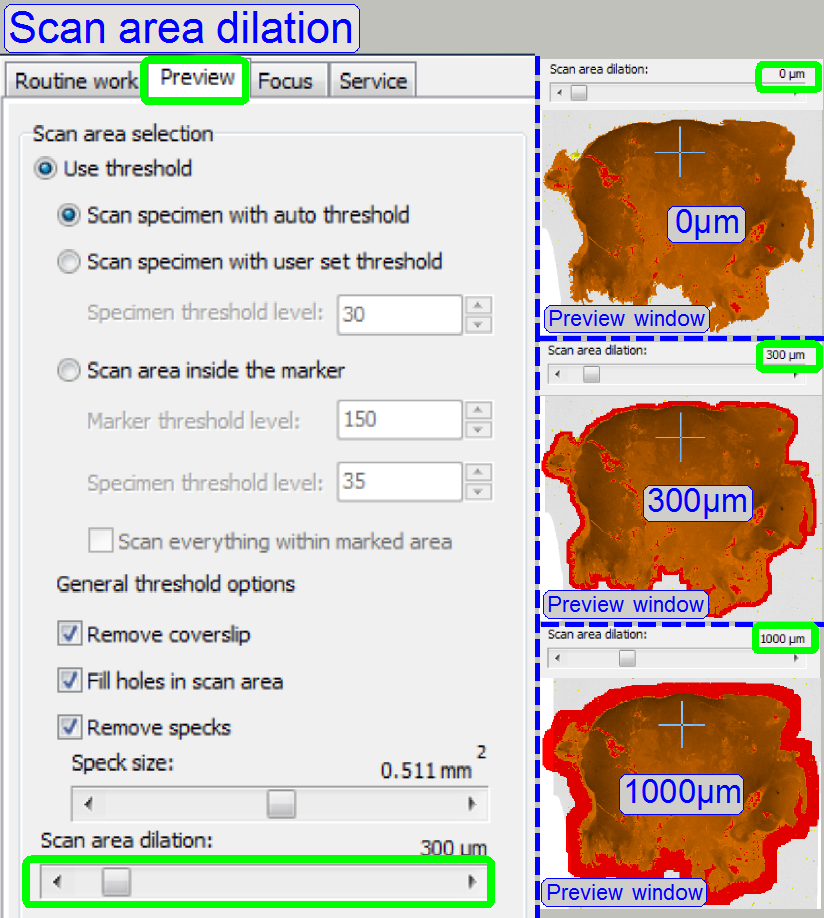 To be sure, the
entire sample will be scanned, dilation can be defined.
To be sure, the
entire sample will be scanned, dilation can be defined.
· Usually, the dilation’s
size is between 300 and 1000μm, seldom above.
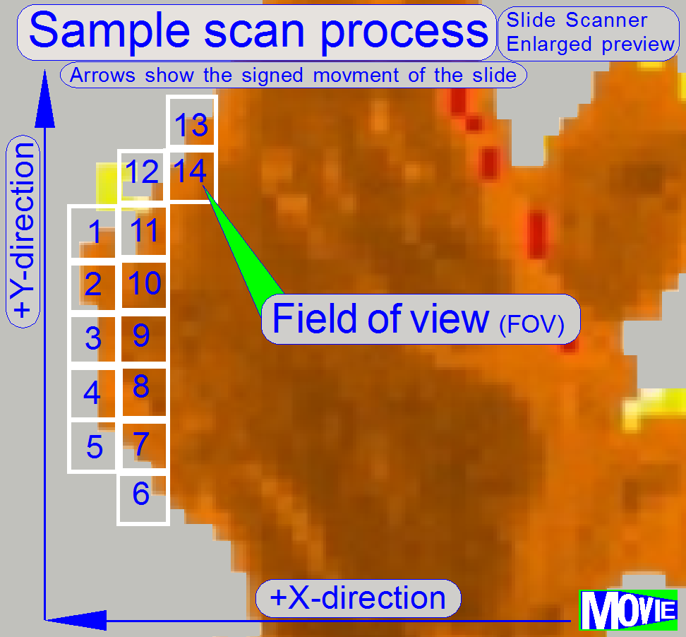
The software
divides the sample to be scanned, seen by the preview camera into fields of
views; the size of the FOV depends on the resolution of the scan camera and the
magnification of the camera adapter and of course, the magnification of the
objective. Each field of view contains a small part of the neighbor FOV. In
this way, stitching becomes possible. Because the capturing of the FOV’s is
done on a meandering course, the Y-direction is often changed. If the
hysteresis in Y-direction is too much, stitching will not work correctly;
therefore, we have to check the hysteresis in Y-direction. The maximal allowed
hysteresis is 4 μm (=4 motor steps).
First, we are discussing the preview image path related to the pixel
size of the preview camera and then, we calculate the entire view of the
preview camera. This algorithm is more precise in relation to other techniques,
because all dimensions will be referenced to the slide surface and can be
handled in [μm].
· If we are doing
the same procedure with the FOV of the scan camera (later in this chapter),
differences between the position of the FOV in relation to the start point of
the preview camera’s view can be eliminated and so, starting co-ordinates of
both views can be fit to each other.
The distance of the preview objective to the slide may vary in a small range,
because we adjusting the preview camera’s position and its rotation angle.
· By adjusting the
focus of the preview objective and / or the position of the preview camera, the
magnification of the objective will be a bit affected.
· To avoid
confusion, we are not using the term FOV (Field Of View) for the preview
camera, we using the term “Preview camera view” instead!
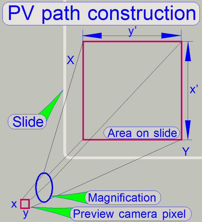
The seen area on the slide
can be calculated as follows:
Seen preview camera area pro pixel = (Preview camera pixel size) *
(Preview objective magnification)
 Example calculations
|
Camera |
Effective pixel
array size |
Active pixel size |
||
|
(H) pixels |
(V) pixels |
(H) µm |
(V) µm |
|
|
2056 |
1544 |
3.2 |
3.2 |
|
|
Used: |
2048 |
1536 |
3.2 |
3.2 |
|
640 |
480 |
5.6 |
5.6 |
|
Preview objective magnification DFK 21F04 ~ 8.2
Preview objective magnification Tamron (VRmagic) ~ 4.7
Seen slide area / pixel X
[µm] = (Preview camera pixel size X) * (Preview objective magnification)
Seen slide area / pixel Y
[µm] = (Preview camera pixel size Y) * (Preview objective magnification)
So we can say:
x’ = 5.6 x 8.2 Seen
preview camera area pro pixel x’ (DFK 21F04 (H)) = ~46 µm
y’ = 5.6 x 8.2 Seen
preview camera area pro pixel y’ (DFK 21F04 (V)) = ~46 µm
x’ = 3.2 x 4.7 Seen preview
camera area pro pixel x’ (VRmagic (H)) = 15.04 or ~15µm
y’ = 3.2 x 4.7 Seen
preview camera area pro pixel y’ (VRmagic (V)) = 15.04 or ~15µm
The CCD size of the preview camera DFK 21F04 is
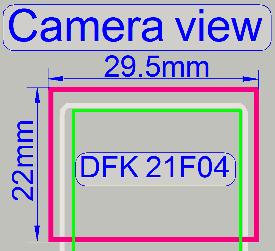 640 (H) x 480 (V) pixels.
If we are multiplying the value
of the seen area on the slide with the number of pixels (H) the result is
~29.5mm
and multiplied with the number of pixels (V) the result is ~22mm.
· The preview
camera’s view (DFK 21F04) has a size of 29.5mm
x 22mm.
Because the preview camera’s view is stitched and cut to the Scan Area
on the slide, a width of approximately 24.5mm is used.
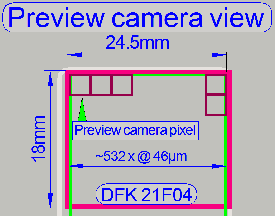
By dividing this value by the width of the preview camera pixel width on
the slide (46μm), the used pixel number is approximately 532 preview
camera pixels horizontal.
The
same calculations can be executed with the preview camera VRmagic; the
principle is the same.
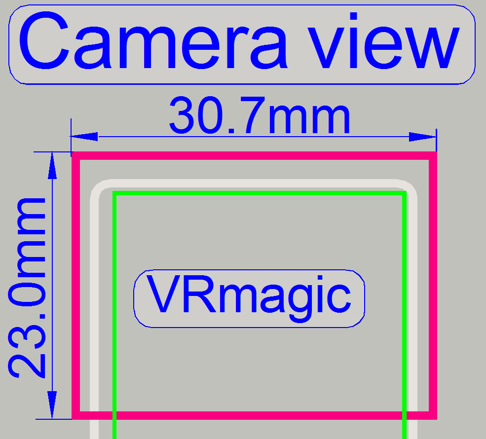
The used sensor size of the preview camera VRmagic is
2048 (H) x 1536 (V) pixels.
If we are multiplying the value
of the seen area on the slide 15µm with the number of pixels (H) 2048 the result is
30.72mm
and
multiplied with the number of pixels (V) the result is 23.04mm.
· The preview
camera’s view (VRmagic) has a size of 30.7mm
x 23.0mm.
One pixel of the preview camera
VRmagic sees an area of 15 x 15µm on the slide.
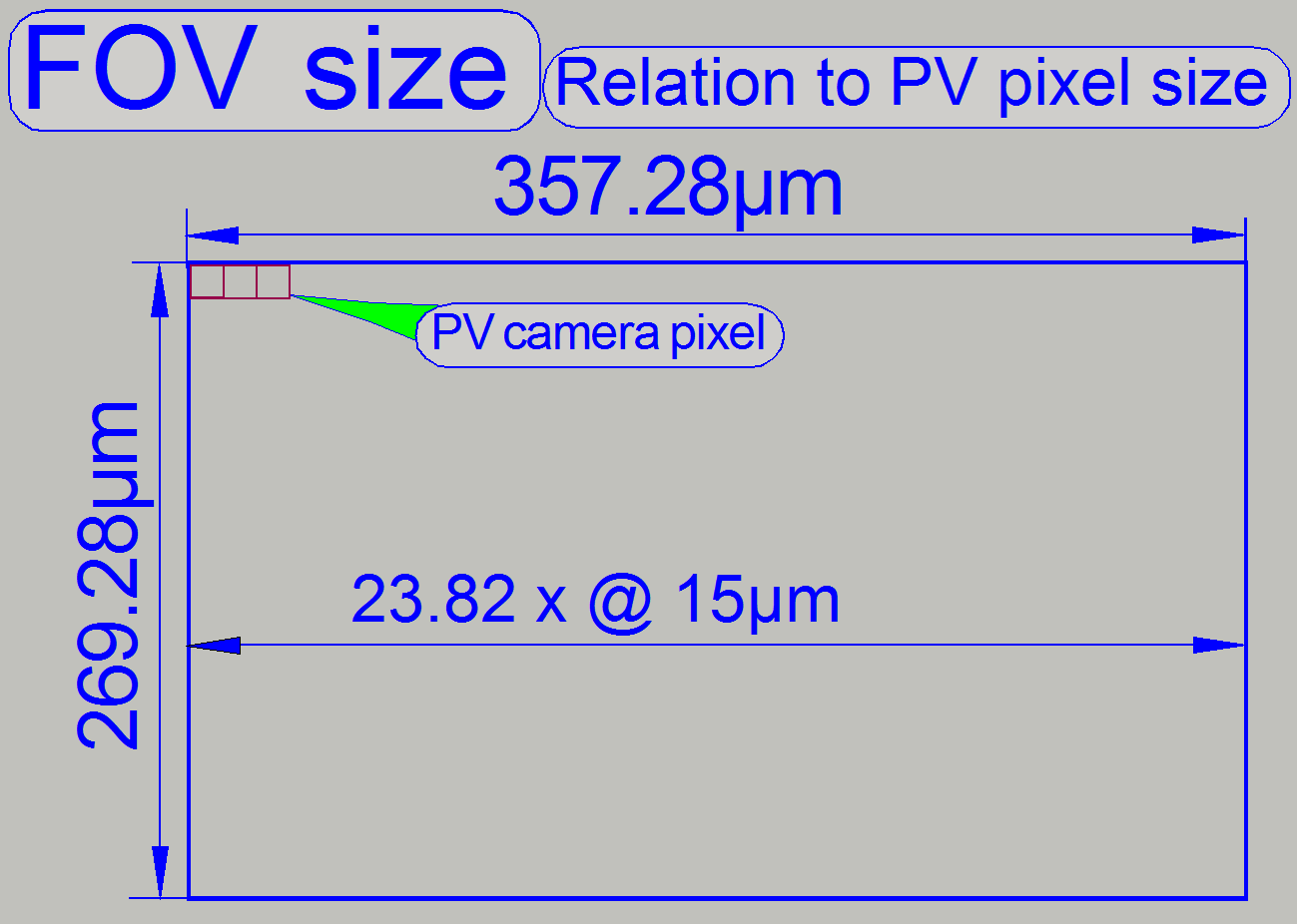
· This area (FOV size:
see the example FOV size) is
seen by the scan camera on the slide within ~ 24 x 18 pixels of the preview
camera (VRmagic).
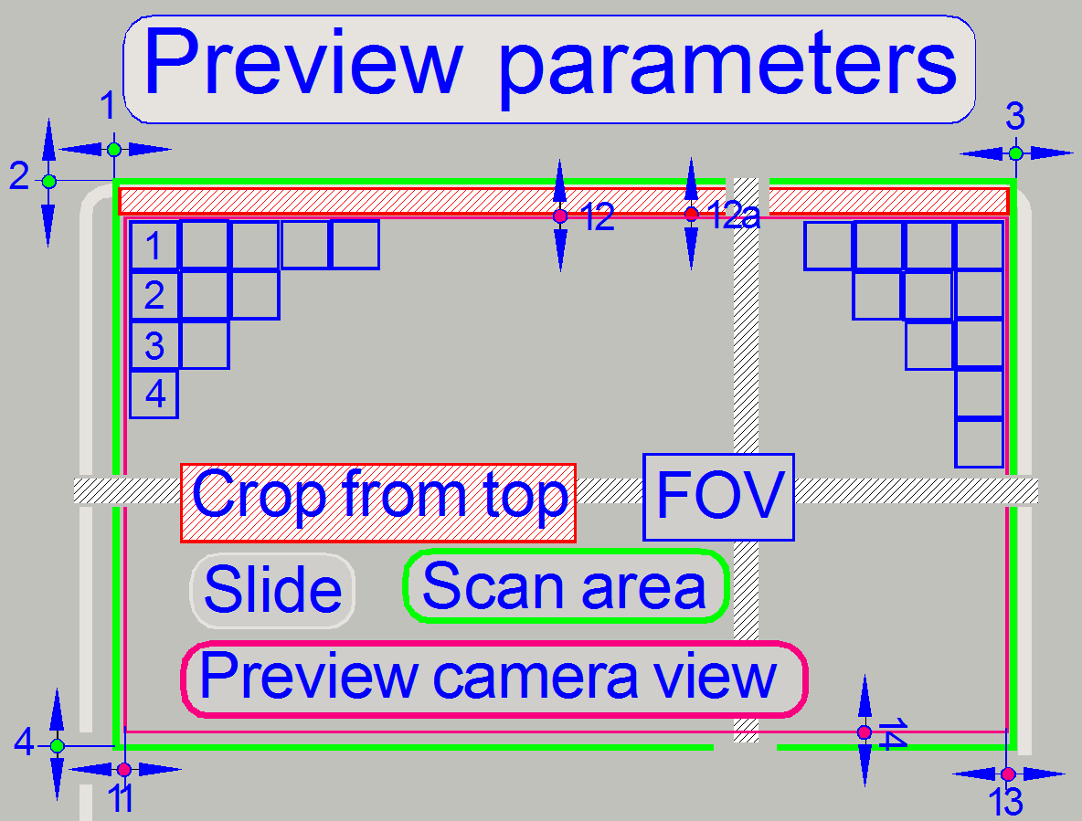 The following
parameters (and others) are influenced during the preview calibration process.
The following
parameters (and others) are influenced during the preview calibration process.
· Parameters used
for the pixel position adjustment are shown only!
· See also: “Handling the *.ini files”
and “PreviewAndBarcodeScanning”
[HardwareLimits]
These values are defined before the preview calibration process starts!
![]() 1 =
ScannableAreaXMin
1 =
ScannableAreaXMin
2 = ScannableAreaYMin
3 = ScannableAreaXMax
4 = ScannableAreaYMax
Following parameter values are defined during the preview calibration
process!
[PreviewAndBarcodeScanning]
![]() 11 = PreviewCropLeft
11 = PreviewCropLeft
12 = PreviewCropTop;
often zero, its value is included in “Crop from Top”
12a = Crop From Top;
13 = PreviewCropRight
14 = PreviewCropBottom
FOV size: see the example FOV size
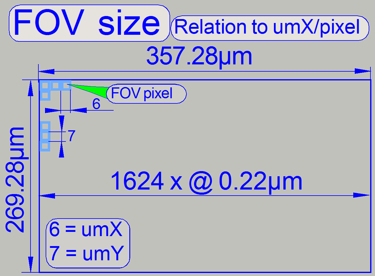
6 = umX/Pixel
7 = umY/Pixel
These values are defined by the used optics in the image path of the
scan camera!
umX/pixel [µm] = (CCD X pixel size (H)) / (objective magnification *
camera adapter magnification)
umY/pixel [µm] = (CCD Y pixel size (V)) / (objective magnification *
camera adapter magnification)
PreviewImageTopLeftCornerPositionX
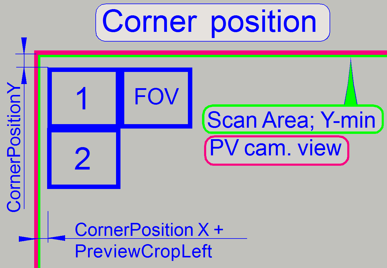 PreviewImageTopLeftCornerPositionX
= ScannableAreaXMin
PreviewImageTopLeftCornerPositionX
= ScannableAreaXMin
· The values of
PreviewImageTopLeftCornerPositionX and ScannableAreaXMin are identical.
CornerPositionY =
PreviewImageTopLeftCornerPositionY
CornerPositionX =
PreviewImageTopLeftCornerPositionX
· The value of the
parameter “PreviewImageTopLeftCornerPositionY” defines the starting FOV’s
position in Y-direction. The value of the parameter “ScannableAreaYmin” will be
set to the calculated value of “PreviewImageTopLeftCornerPositionY” after the
preview calibration procedure is finished.
· The X-value for
the start position of the first FOV is defined by the value of “PreviewImageTopLeftCornerPositionX” and the
value of “PreviewCropLeft”
Optical path and Field Of View
 The pupil of the scan
objective is very close to the tissue, so, the small area on the tissue will be
enlarged by the objective and the camera adapter.
The pupil of the scan
objective is very close to the tissue, so, the small area on the tissue will be
enlarged by the objective and the camera adapter.
The seen area on the slide is always defined by the size of the camera’s
CCD; more precise, the effective number of pixels horizontal and vertical and
the optical means in the image path.
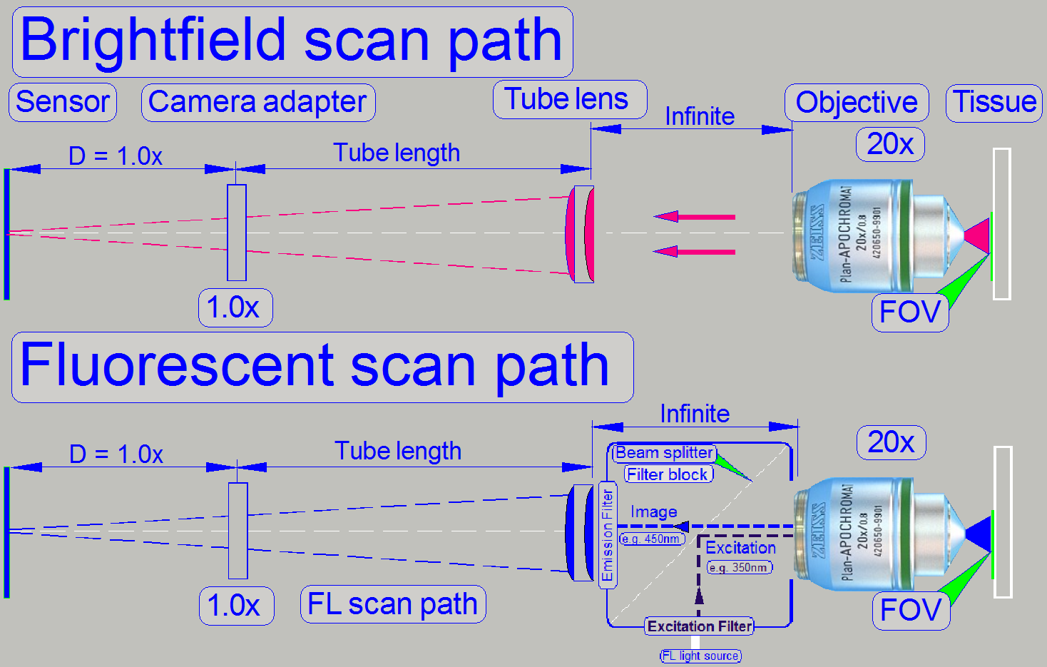
The objective type “Plan-Apochromat” requires a tube lens to create the
image. In opposite to other objective types, an infinite space exists between
the objective and the tube lens, in which the light
rays are parallel.
So, optical means, like the filter block in fluorescent
scan sessions can be inserted (by the help of the turret unit)
· The filter block’s
components do not affect the magnification of the image path!
Remark
Links refer to P250!
Calculate the FOV pixel size
Example

If we assume that the scan camera has the named values (see below), we
can easily calculate the area for 1 pixel, seen on the slide; this is also the
maximal resolution in the optical path for the example construction. If the
calculation is done with an objective magnification of 20x and the camera
adapter magnification should be 1x, the result will be:
CIS-
VCC-F52U25CL
Effective Pixel Number: 1624
(H) × 1224 (V)
Unit Cell Size: 4.40μm
(H) × 4.40μm (V)
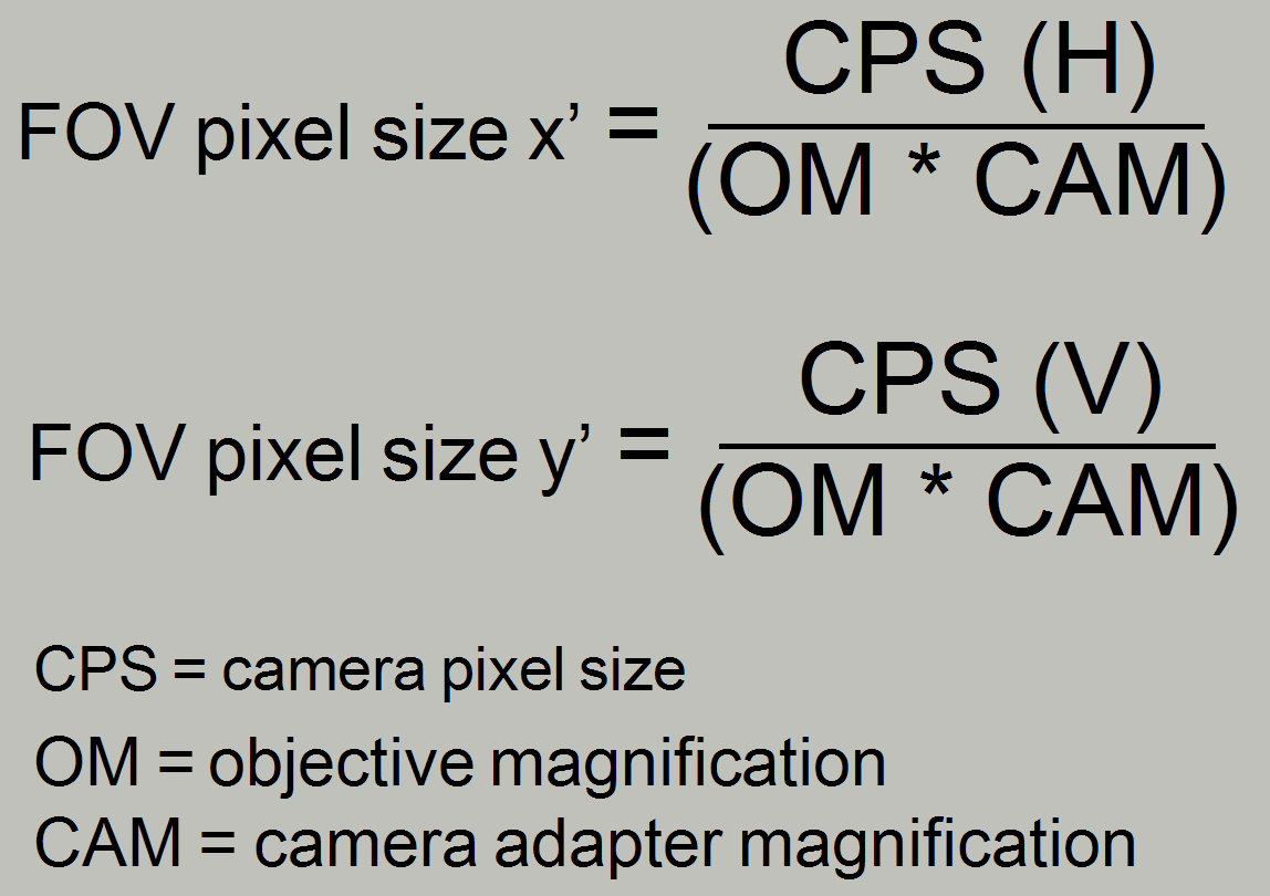
x’ [μm] =
4.40 (H) divided by 20 = 0.22μm or 220nm
y’[μm] = 4.40(V) divided by 20 = 0.22μm
or 220nm
The value of x’ is also named as umX/pixel [µm] and
The value of y’ is also named as umY/pixel
[µm]
If the values are multiplied with the effective number of pixels (H) and
(V) the result will be:
0.22 x 1624 = 357.28 [μm] (H) and
0.22 x 1224 = 269.28 [μm] (V)
So the dimension of the FOV for this example image path will be
Example
FOV size: Slide X-direction 357.28µm (H) x Slide Y-direction 269.28µm (V)!
· The real dimension of the FOV depends highly on the
optical means, used in the image path!
Influence of the camera adapter
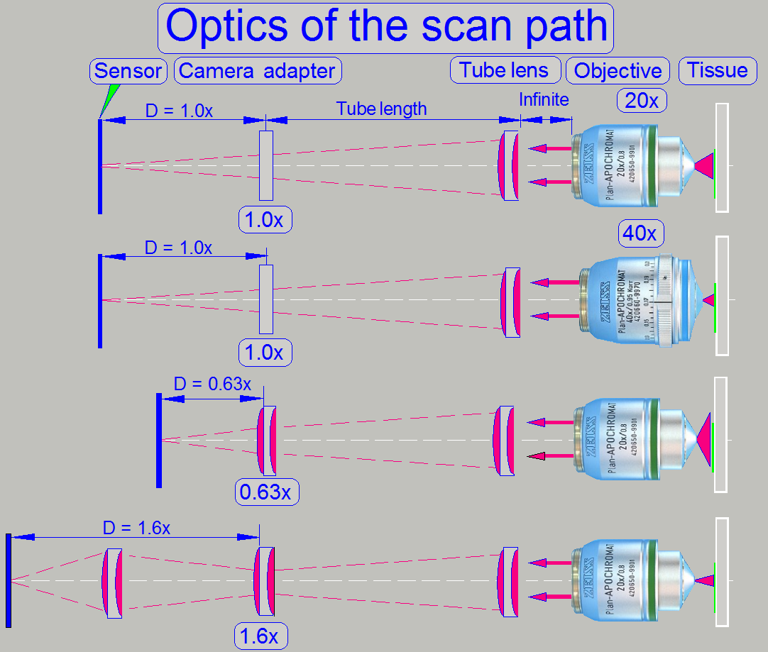
The useable magnification of the camera adapter depends on the size of
the sensor (useable geometry x and y in pixels), the used objective
magnification and the construction of the image path (Length of the camera
tube).
· The resulting
magnification of the image path is defined by the product of Objective
Magnification multiplied by the Camera Adapter Magnification.
Example
If the Objective Magnification is 20x and the camera adapter
magnification is 0.63x the resulting magnification of the image path will be
12.6x.
Image
magnification = 20 x 0.63 = 12.6
Advantage
By reducing the image
magnification, the dimension of the FOV will be increased; the scan speed
increases because the number of FOVs to be scanned is reduced.
Disadvantage
The resolution of the virtual
tissue is reduced.
Conclusion
· The camera adapter
fits the image, seen by the objective in the focus of the camera sensor and
influences the resulting magnification of the image path and the size of the
FOV.
· If the camera adapter
magnification is 1x, then no lenses are inserted, and the sensor is in the
focus of the tube lens; the optical magnification is defined by the objective
magnification.
· If the camera
adapter magnification is 0,63x, then the lens of the camera adapter enlarges
the FOV; the resolution of the scanned tissue is decreased.
· If the camera
adapter magnification is 1,6x, then the optics of the camera adapter makes the
FOV smaller, and the resolution of the scanned tissue is increased!
|
Preview
cameras |
||||
|
Camera |
Effective pixel
array size |
Active pixel
size |
||
|
(H) pixels |
(V) pixels |
(H) µm |
(V) µm |
|
|
2056 |
1544 |
3.2 |
3.2 |
|
|
Used: |
2048 |
1536 |
3.2 |
3.2 |
|
640 |
480 |
5.6 |
5.6 |
|
Preview camera pixel view =
(Preview camera pixel size) * (Preview objective magnification)
Preview objective magnification DFK 21F04 ~ 8.2x
Preview objective magnification VRmagic ~ 4.7x
·
Preview camera pixel view DFK 21F04 = 46µm
·
Preview camera pixel view VRmagic = 15µm
|
Useable magnifications
and resulting resolutions of scan (main) cameras |
|||||||||||
|
Camera |
Pixel array size used ; [Pixels] |
Pixel size [µm] |
Useable Magnification; Resolution [µm] |
||||||||
|
Active |
Valid |
0.63x |
1.0x |
1.6x |
|||||||
|
(H) |
(V) |
(H) |
(V) |
(H or V) |
20x |
40x |
20x |
40x |
20x |
40x |
|
|
Grasshopper3; color* 3) |
2448 |
2048 |
3.45 |
3.45 |
4.87* |
0.39 |
0.19 |
0,24 |
0.12 |
X |
X |
|
1380 |
1030 |
4.65 |
4.65 |
6.58* |
0.52 |
0.26 |
0.33 |
0.16 |
X |
X |
|
|
Marlin* 1) |
1368 |
1024 |
4.65 |
4.65 |
6.58* |
0.52 |
0.26 |
0.33 |
0.16 |
X |
X |
|
4096 |
3072 |
5.5 |
5.5 |
7.78* |
X |
X |
X |
X |
0.24 |
0.12 |
|
|
1624 |
1224 |
4.40 |
4.40 |
4.40 |
0.35 |
0.18 |
0.22 |
0.11 |
X |
X |
|
|
2048 |
2048 |
5.5 |
5.5 |
7.78* |
X |
X |
0.39 |
0.19 |
0.24 |
0.12 |
|
|
1360 |
1024 |
4.65 |
4.65 |
4.65 |
0.37 |
0.18 |
0.23 |
0.12 |
X |
X |
|
|
Sony DFW-X710*
1) |
1024 |
768 |
4.65 |
4.65 |
6.58* |
0.52 |
0.26 |
0.33 |
0.16 |
X |
X |
|
Monochrome scan cameras (FL or RGB illuminated) |
|||||||||||
|
2448 |
2048 |
3.45 |
3.45 |
3.45 |
0.27 |
0.14 |
0,17 |
0.08 |
X |
X |
|
|
1388 |
1040 |
6.45 |
6.45 |
6.45 |
X |
X |
0.32 |
0.16 |
X |
X |
|
|
2048 |
2048 |
6.5 |
6.5 |
6.5 |
X |
X |
0.32 |
0.16 |
X |
X |
|
|
PCO-edge 5.5_@
2.5Mp |
1600 |
1600 |
6.5 |
6.5 |
6.5 |
X |
X |
0.32 |
0.16 |
X |
X |
|
PCO-edge 5.5_@
4.0Mp |
1920 |
1920 |
6.5 |
6.5 |
6.5 |
X |
X |
0.32 |
0.16 |
X |
X |
|
PCO-edge 5.5_PCON |
2560 |
2160 |
6.5 |
6.5 |
6.5 |
X |
X |
0.32 |
0.16 |
X |
X |
X)
Not defined, can not be used
* Calculations for
these cameras are done by using the factor sqrt(2)
Resolution [µm] = (Active camera pixel size * sqrt(2) ) /
(objective magnification * camera adapter magnification); used if single chip
camera with Bayer method
· sqrt(2)= required,
because debayering (creation of color information in single chip cameras with Bayer method); and generation
of JPEG file
If real color camera or monochrome (FL)
camera:
Resolution [µm] = (Active camera pixel size) / (objective
magnification * camera adapter magnification)
1) No longer delivered
2) Useable since SW
version 1.20 only!
3) Useable since SW
version 1.21only!
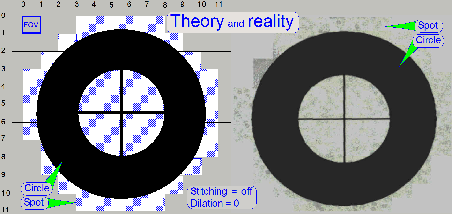
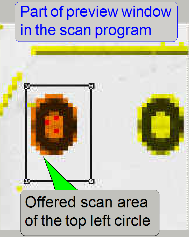
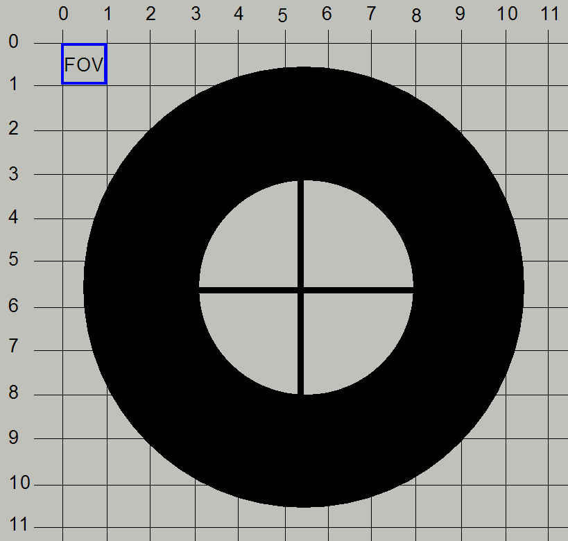
Pixel position and corrections
If the preview calibration procedure is just finished and we scan one of
the circles, the offered area to be scanned, offered by the preview window in
the SlideScanner.exe, mostly will not fit the real position of the circle.
Parts of the circle will be cut.
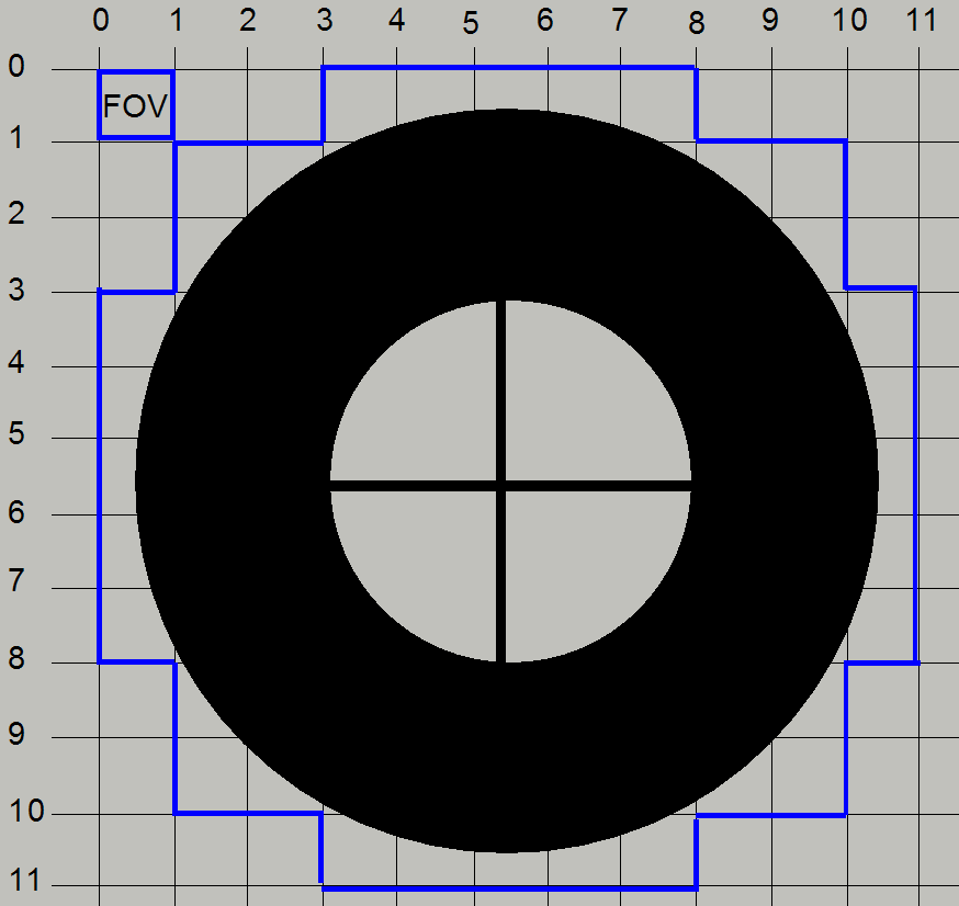
· Check the FOV
position of the scan camera in relation to the pixel position of the preview
camera.
Adjust the pixel
position of the preview camera to the field of view of the scan camera.
The goal of this adjustment
is, to see the same part of the tissue with the scan camera and the preview
camera also.
This task is done
by the preview calibration program, but the software is not able to find this
position correctly. Therefore, we need to adjust the position of the pixel of
the preview camera more precise to the position of the field of view of the
scan camera “manually” by modifying pre-calculated parameter values.
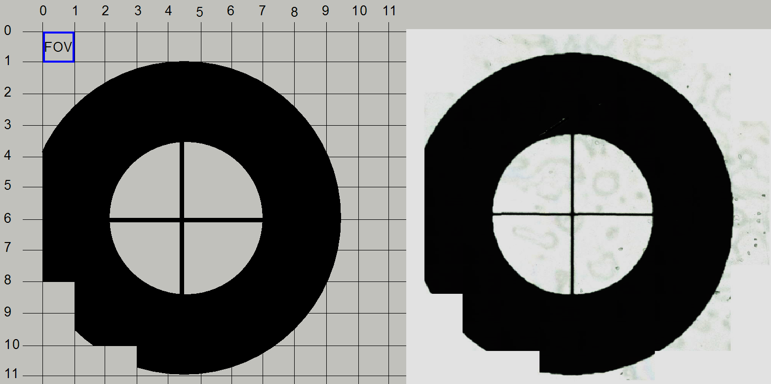
As shown on the
right the scan program offers in the preview window the entire circle for scanning
(dilation=0; the red-brown area).
By checking the
scan result with the viewer, we can see, the circle is cut, so the position of
the offered area is incorrect.
·
The size and position of the cut part is
variable.
This chapter
describes which parameter values must be modified to fit both areas.
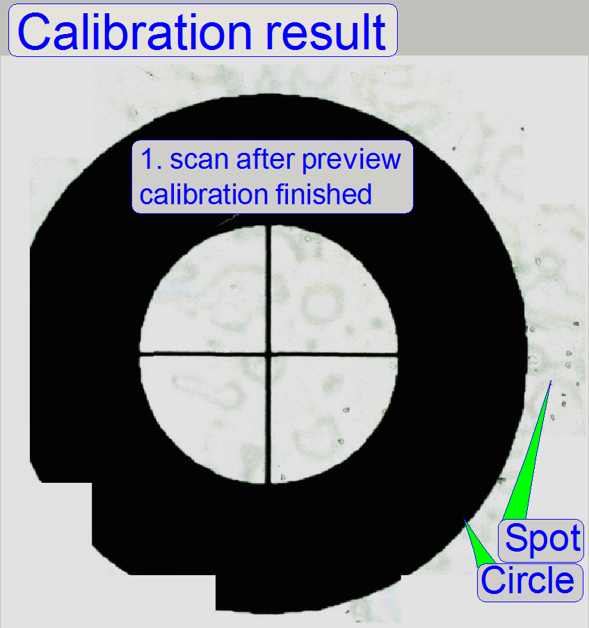
Important remarks
·
The offered scan area, offered by the
preview camera’s view, will be named as “Spot”
·
The really scanned area is represented by
the “Circle”.
·
Of course, the entire area is scanned by the
scan camera, but our reference position will be the center of the circle in
relation to its surrounding.
·
In the picture above, the circle is cut,
this means, the offered area for scanning (offered by the preview camera) will
not met the real position of the circle on the slide.
·
Therefore, we have to shift the offered
preview area (the spot) to the left and a bit downward; so we will see the
circle in the center of the offered scan area.
·
All modifications, described below are
done with the offered scan area, offered by the preview camera’s view!
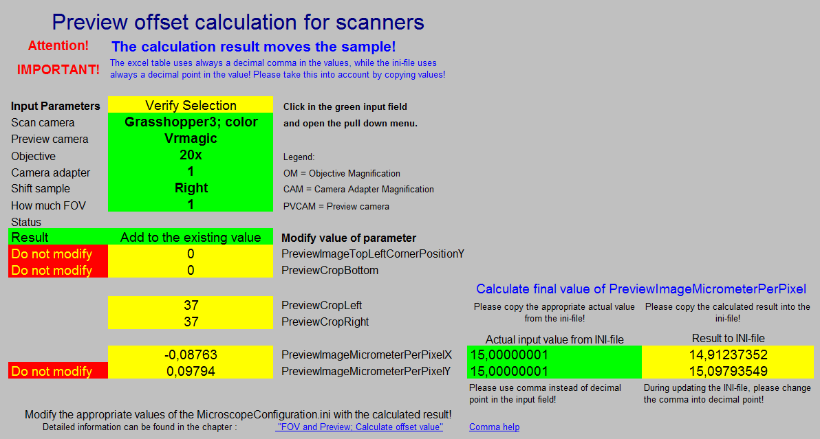
Calculate required offset value
 See
also: “Preview_S_M_D”
and “Adjust the
pixel position of the preview camera”
See
also: “Preview_S_M_D”
and “Adjust the
pixel position of the preview camera”
“P250_Preview” and “Adjust the pixel
position of the preview camera”
If the status message “OM or
Nevertheless, the
calculated result is always correct for all selected combinations!
·
See also the table above “Scan (main) cameras”
·
The camera “PCO-edge
5.5_PCON” can not be used in conjunction with the DFK 21F04,
but the result is even so correct!
PreviewImageMicrometerPerPixelX
If the value of
the Parameter "Shift sample" is Left or right, the right hand circles are shifted to the
left or to the right, as the selected value shows.
Because the value
of PreviewImageMicrometerPerPixelX
affects mainly the right hand circles, these will be shifted to the left
or to the right, by the calculation result.
PreviewImageMicrometerPerPixelY
If the value of
the Parameter "Shift sample" is Up or Down, the lower circles are shifted Up or Down, as
the selected value shows.
Because the value
of PreviewImageMicrometerPerPixelY
affects mainly the bottom circles, these will be shifted up or down, by
the calculation result.
 If we assume, the
image on the right shows the scan result of the circle, we can say, the circle
position fits not the center of the offered scan area (offered by the preview),
the circle must be shifted to the right and upward a bit to meet the center of
the spot.
If we assume, the
image on the right shows the scan result of the circle, we can say, the circle
position fits not the center of the offered scan area (offered by the preview),
the circle must be shifted to the right and upward a bit to meet the center of
the spot.
·
In reality, we are always shifting the offered preview scan area of the circle,
named as spot.
·
In the example on the right, the offered scan area
have to be shifted to the left and a bit downward.
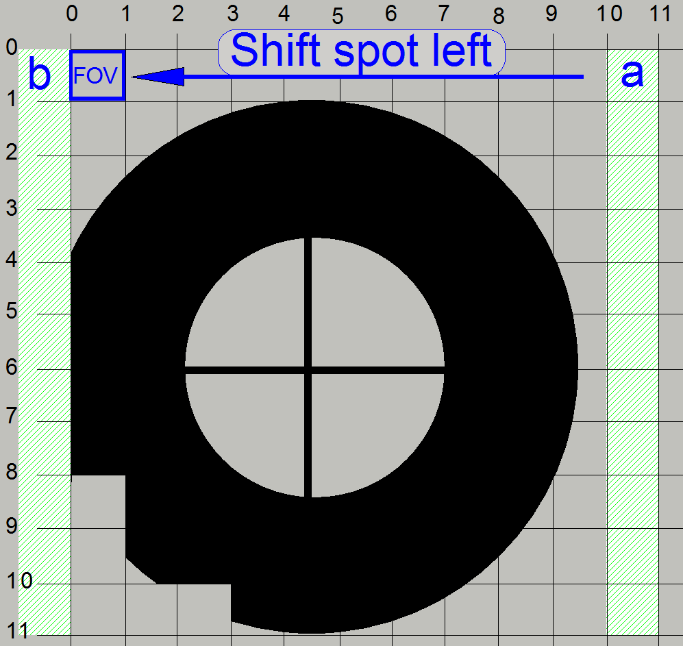 If we are shifting
the entire spot to the left by the size of 1 FOV, the FOV column, shown with
“a” will be cut and the content of the FOV column, shown with “b” will be seen,
the circle stays seemingly unchanged.
If we are shifting
the entire spot to the left by the size of 1 FOV, the FOV column, shown with
“a” will be cut and the content of the FOV column, shown with “b” will be seen,
the circle stays seemingly unchanged.
This way, because the offered area for 1 circle has not changed (only
its position was moved) the circle can be fit to the center of the offered scan
area for the circle.
Shift
sample right
See: “Important”
"PreviewCropLeft" = (Number of FOVs) x ((FOV X-dimension) /
(PVcam µmX/pixel))
"PreviewCropRight" = (Number of FOVs) x ((FOV X-dimension) /
(PVcam µmX/pixel))
·
Add the result to or subtract the result from the
existing value of "PreviewCropLeft" and "PreviewCropRight".
The image on
the right is conventionalized!
· We know that the real
FOV’s dimension depends on the optical means, used in the scan image path and
the sensor dimensions!
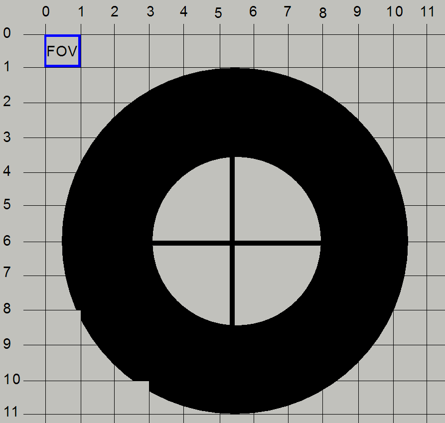 The result is
shown on the right.
The result is
shown on the right.
The image on
the right is conventionalized!
· We know that the real
FOV’s dimension depends on the optical means, used in the scan image path and
the sensor dimensions!
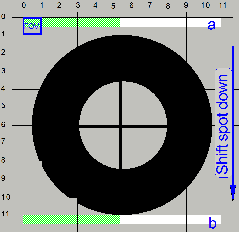 If we are shifting
the spot by a half FOV size downward, the upper part, shown with “a” will be cut
and the part, shown with “b” will be displayed. The circle moves seemingly
upward.
If we are shifting
the spot by a half FOV size downward, the upper part, shown with “a” will be cut
and the part, shown with “b” will be displayed. The circle moves seemingly
upward.
Shift
sample up
See: “Important”
"PreviewImageTopLeftCornerPositionY" = (Number of FOVs) x (FOV
Y-dimension)
"PreviewCropBottom" = -
("PreviewImageTopLeftCornerPositionY" / (PVcam µmY/pixel))
FOV Y-dimension [μm] = (Camera pixel size [μm] / (Objective
magnification x
The image on
the right is conventionalized!
· We know that the
real FOV’s dimension depends on the optical means, used in the scan image path
and the sensor dimensions!
Expected result
·
 No
parts of the circle are cut!
No
parts of the circle are cut!
The image on
the right is conventionalized!
· We know that the
real FOV’s dimension depends on the optical means, used in the scan image path
and the sensor dimensions!
Calculate required values
Scan camera
 umX/pixel [µm] =
(Sensor (H) pixel size [µm]) /
(objective magnification * camera adapter magnification)
umX/pixel [µm] =
(Sensor (H) pixel size [µm]) /
(objective magnification * camera adapter magnification)
umY/pixel [µm] = (Sensor (V)
pixel size [µm]) / (objective magnification * camera adapter
magnification)
sqrt(2)= required, because debayering; (create color information in
single chip cameras with Bayer method) and generation of JPEG file
FOV pixel size = (Scan camera pixel size) / (objective magnification *
camera adapter magnification)
· Add the result of
the following calculations to or subtract the result from the existing value of
the appropriate parameter value.
Following formulas are prepared so, that the movement of the circle will
be executed.
· E.g.: If we using the formula “Shift sample up”,
the circle will be moved upward!
The image on
the right is conventionalized!
· We know that the
real FOV’s dimension depends on the optical means, used in the scan image path
and the sensor dimensions!
FOV Pixel size =Camera pixel size / (Objective magnification x
FOV size x = FOV pixel size x’ [μm] * Sensor (H) [pixels]
FOV size y = FOV pixel size y’ [[μm] * Sensor (V) [pixels]
umX/pixel [μm] = FOV Pixel size x' [μm] = Camera pixel size (H) [μm] / (Objective magnification x
umY/pixel [μm] = FOV Pixel size y' [μm] = Camera pixel size (V) / (Objective
magnification x
FOV X-dimension [μm] = ((Camera pixel size [μm] / (Objective magnification x
FOV Y-dimension [μm] = ((Camera pixel size [μm] / (Objective
magnification x
Shift sample up
"PreviewImageTopLeftCornerPositionY" = (Number of FOVs) x
(Camera pixel size [μm] /
(Objective magnification x
"PreviewCropBottom" = -
("PreviewImageTopLeftCornerPositionY" / (PVcam µmY/pixel))
Shift sample down
"PreviewImageTopLeftCornerPositionY"=
- ((Number of FOVs) x (FOV Y-dimension))
"PreviewCropBottom" =
("PreviewImageTopLeftCornerPositionY") / (PVcam µmY/pixel))
Shift sample right
"PreviewCropLeft" = +(((Number of FOVs) x (FOV X-dimension)) /
(PVcam µmX/pixel))
"PreviewCropRight" = +(((Number of FOVs) x (FOV X-dimension))
/ (PVcam µmX/pixel))
Shift sample left
"PreviewCropLeft" = - (((Number of FOVs) x (FOV X-dimension))
/ (PVcam µmX/pixel))
"PreviewCropRight" = - (((Number of FOVs) x (FOV X-dimension))
/ (PVcam µmXpixel))