Preview unit; S_M_D
For technicians and
partly for sales managers!
 To
find the position of the entire tissue to be scanned or parts of it, a preview
of the slide is made. The tissue is defined as a darker part of the slide in relation
to its surrounding. Because dust, grease or fingerprints (specks) fulfills
often the same requirement as the tissue itself; specks may be viewed as tissue
also. Therefore, the surface of the slide and the cover slip should be as clean
as possible.
To
find the position of the entire tissue to be scanned or parts of it, a preview
of the slide is made. The tissue is defined as a darker part of the slide in relation
to its surrounding. Because dust, grease or fingerprints (specks) fulfills
often the same requirement as the tissue itself; specks may be viewed as tissue
also. Therefore, the surface of the slide and the cover slip should be as clean
as possible.
The following description is based on the Software
version 1.15 and the scanner “Pannoramic SCAN”, the components, procedures and
adjustments are the same in the
The entire preview unit is a part of the scanner unit
and designed to fulfill the following 2 tasks:
Contents
 Service program for Pannoramic scanners
and actual license file
Service program for Pannoramic scanners
and actual license file- Pannoramic Viewer software and actual
license file or dongle
- The
test slide #2
- 0.9, 1.5, 2.5, 3 hex key wrenches
- Deeper knowledge of handling the Pannoramic scan
and Pannoramic Viewer software.
- Already installed
VRmagic driver or installed driver for the camera DFK 21F04.
The version numbers of the service program
“SlideScannerService.exe” and the scan program “SlideScanner.exe” are important,
because the preview calibration program uses program parts (.dll-files) of the
program “SlideScanner.exe”.
Attention: Do not mix the versions of SlideScanner.exe and SlideScannerService.exe!
Always use these programs with the same version number; otherwise the
SlideScannerService.exe program could produce unwanted results and
SlideScanner.exe does not work correctly or even freeze!
Since the software version
1.16 the units of the scanner are configured in the file
“MicroscopeConfiguration.ini”, section [Microscope].
The actual version of the preview unit in the scanner Pannoramic 250 is
defined by the use of the following parameters and values:
[Microscope]
SerialNumber=xxxxx
MicroscopeType=3DMicX
ScanCameraType=
PreviewCameraType=CVrmc_m8_pPro
BarcodeReaderType=PreviewCamera
LoaderType=SL_6Mag_25Slide_NoSensor_Vertical
ReflectorTurretType=RT_3DH_10Pos_Gear
ObjectGuideXYZType=OGXYZ_1
PreviewLightType=PreviewLightUnitType_Type1
Remark
In earlier scanner versions this section may be very
small, only the preview camera type may exist. If parameters and values are
missed, these options are handled like usually for Pannoramic S_M_D.
MicroscopeType=3DMicX
· The
scanner type is defined here: 3DMic5 = DESK 3DMic6 = MIRAX SCAN 3DMic7 =
Depending on the presence of the darkfield preview
illumination there are two parameter values possible in the section
[Microscope].
PreviewLightType=PreviewLightUnitType_Type1; The darkfield preview illumination is
not present; only brifhtfield preview images are possible.
PreviewLightType=PreviewLightUnitType_Type2; if the darkfield preview illumination
unit is present; this enables the creation of the darkfield preview also.
PreviewCameraType=CVrmc_m8_pPro; if
the preview camera is “VRmagic”
PreviewCameraType=DFK_21F04; if
the preview camera is “DFK 21F04”
Principle
of brightfield preview
Brightfield illuminated
preview
 The preview illumination
illuminates the background of the entire field of view of the preview
camera, behind the slide.
The preview illumination
illuminates the background of the entire field of view of the preview
camera, behind the slide.- Because the
slide is much larger then the field of the preview camera’s view, the scan area of the
slide is captured in 3 sections; the made 3 images are rotated, cut and
assembled by software; the required parameters are defined during the preview
calibration process and collected in the section
[PreviewAndBarcodeScanning] of the file MicroscopeConfiguration.ini.
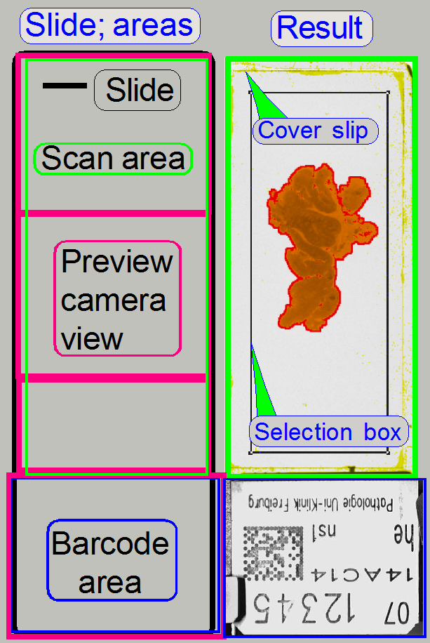
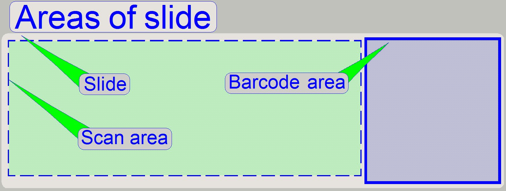
- The assembled
preview, the scan area of the slide, is shown in the preview window of the
slide scanner program.
- The barcode
area is only a little bit smaller than the captured field of the preview
camera’s view and is shown in the barcode window.
![]() “Scan area” and “Barcode area”
“Scan area” and “Barcode area”
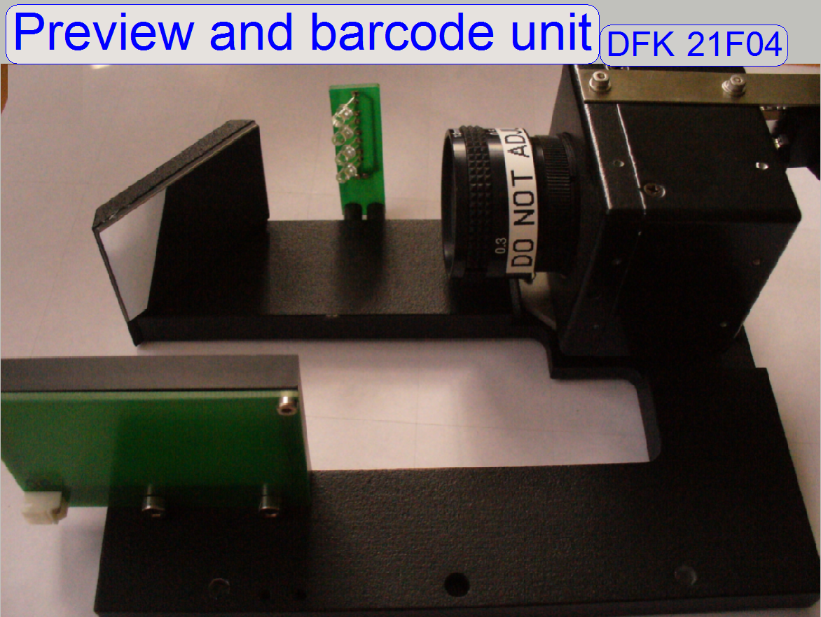
 The
entire preview and barcode unit is situated on the “horseshoe”; and this is a part of the scanner unit.
The
entire preview and barcode unit is situated on the “horseshoe”; and this is a part of the scanner unit.
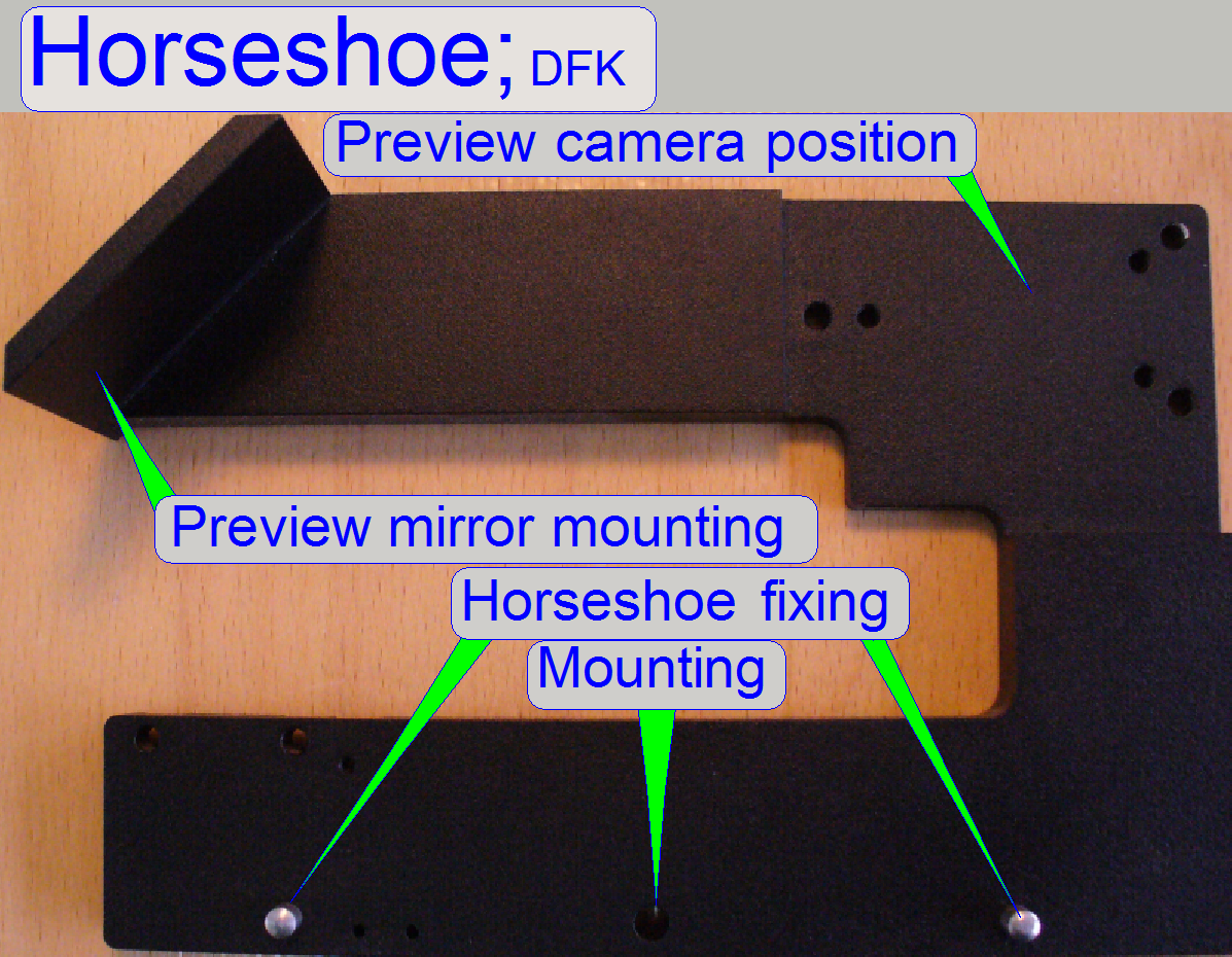
Horseshoe
The horseshoe is a part of the scanner unit, and
contains the following components:
- Objective
and camera holder
- Preview
camera VRmc-8+ PRO
- Preview
objective, TAMRON
23FM16SP
- Preview mirror
- Barcode
illumination
The
preview mirror reflects the image of the preview in an angle of
90 degrees; the mirror does not need adjustments.
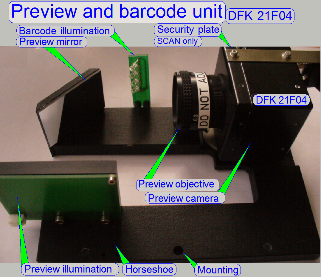
![]() Construction,
Preview camera DFK
21F04
Construction,
Preview camera DFK
21F04
The preview illumination illuminates the background of
the slide in the size of the preview camera’s field of view.
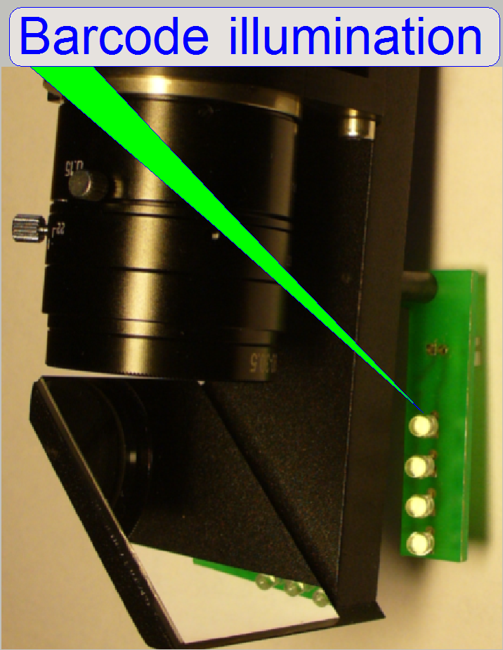 The
barcode illumination consists of four LED’s and these are situated on a small
PCB.
The
barcode illumination consists of four LED’s and these are situated on a small
PCB.
To reach an evenly and bright illuminated barcode area,
the position of the LED’s can be modified by positioning the entire PCB if the
mounting bolts are loosened or by bending the LED’s carefully, separately.
![]() “Barcode adjustments” “Barcode illumination”.
“Barcode adjustments” “Barcode illumination”.
The entire
preview unit is situated on the edge of the scanner plate, parallel to the
magazine unit.
 The
position is fixed with two fixing pins and hold by the mounting bolt.
The
position is fixed with two fixing pins and hold by the mounting bolt.
![]() “Scanner plate” and “Horseshoe mounting”
“Scanner plate” and “Horseshoe mounting”
Remove the
preview unit
· Disconnect
the cables for the preview illumination, the barcode illumination and the
preview camera’s FireWire cable
· Remove
the mounting bolt and then the entire preview unit can be removed frontward.
Mount the preview
unit
· Fit
the fixing pins of the scanner unit into the position fixing holes of the
horseshoe and push the entire preview unit onto the edge of the scanner unit.
· Drive
in the mounting bolt.
· Connect
the cables for the preview illumination, the barcode illumination and the
preview camera’s FireWire cable
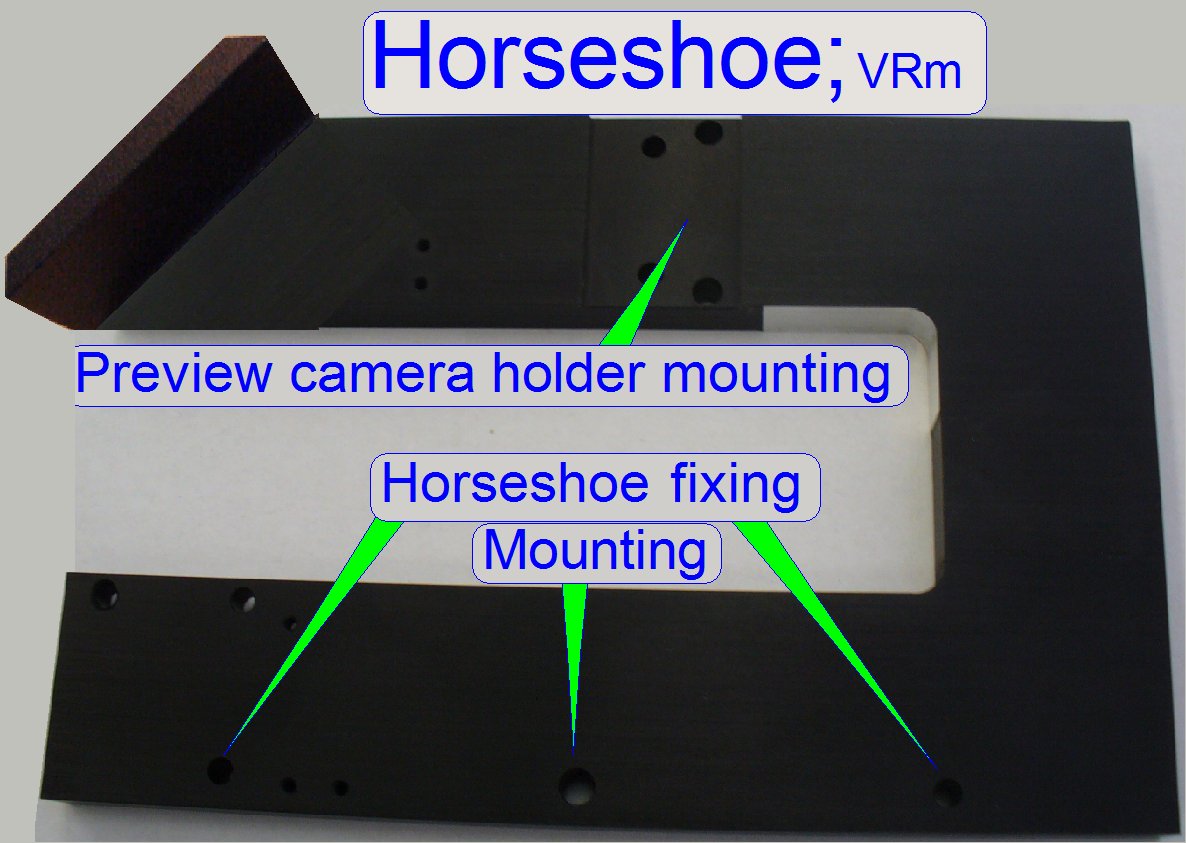 Because
the production of the preview camera “DFK 21F04” was discontinued, the scanners
S_M_D are delivered since spring 2013 with the camera VR magic “VRmc-8+ PRO”.
Because
the production of the preview camera “DFK 21F04” was discontinued, the scanners
S_M_D are delivered since spring 2013 with the camera VR magic “VRmc-8+ PRO”.
· The
horseshoe is modified to the requirements of the camera and objective holder
for the camera VR magic “VRmc-8+ PRO”.
· The
construction of the camera mounting is the same as in the P250.
Preview camera and objective holder
Camera DFK 21F04
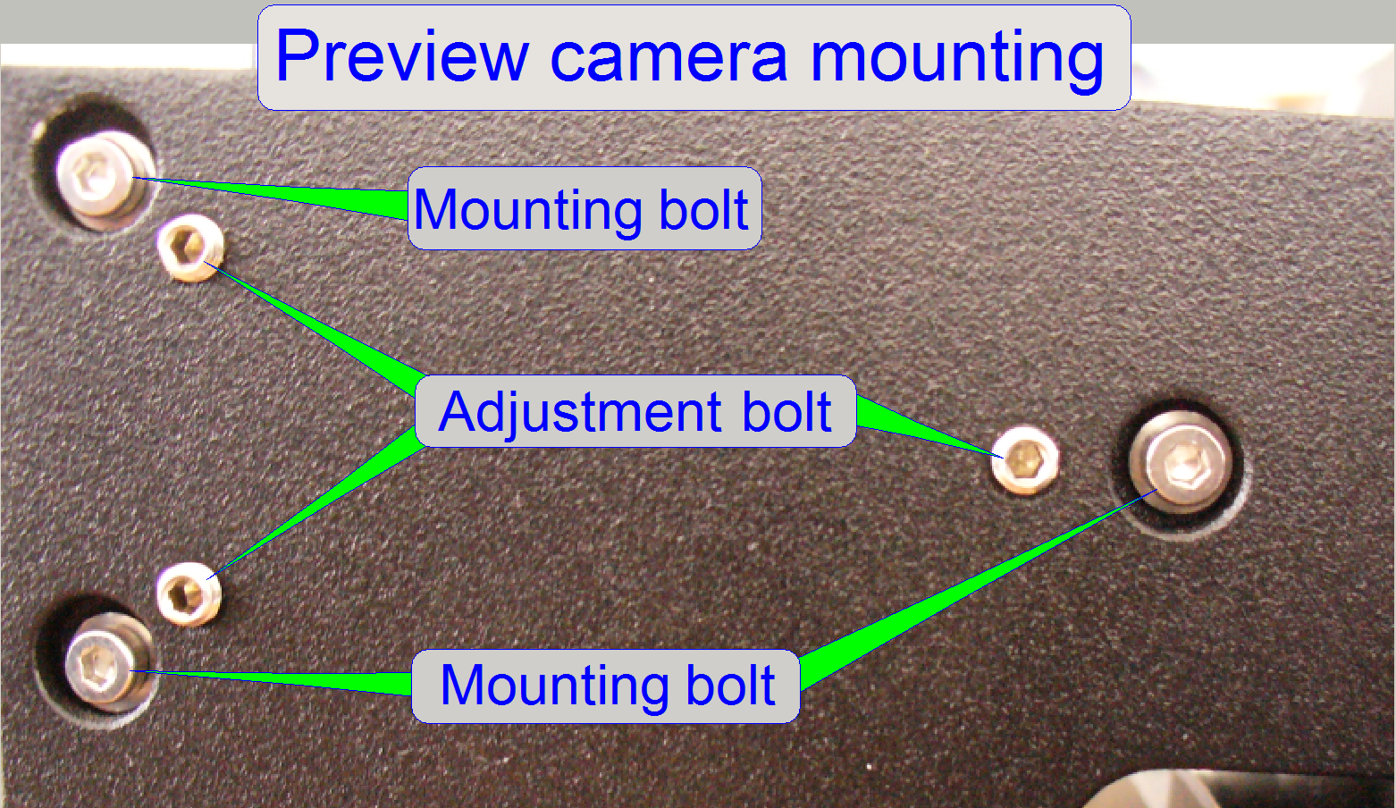
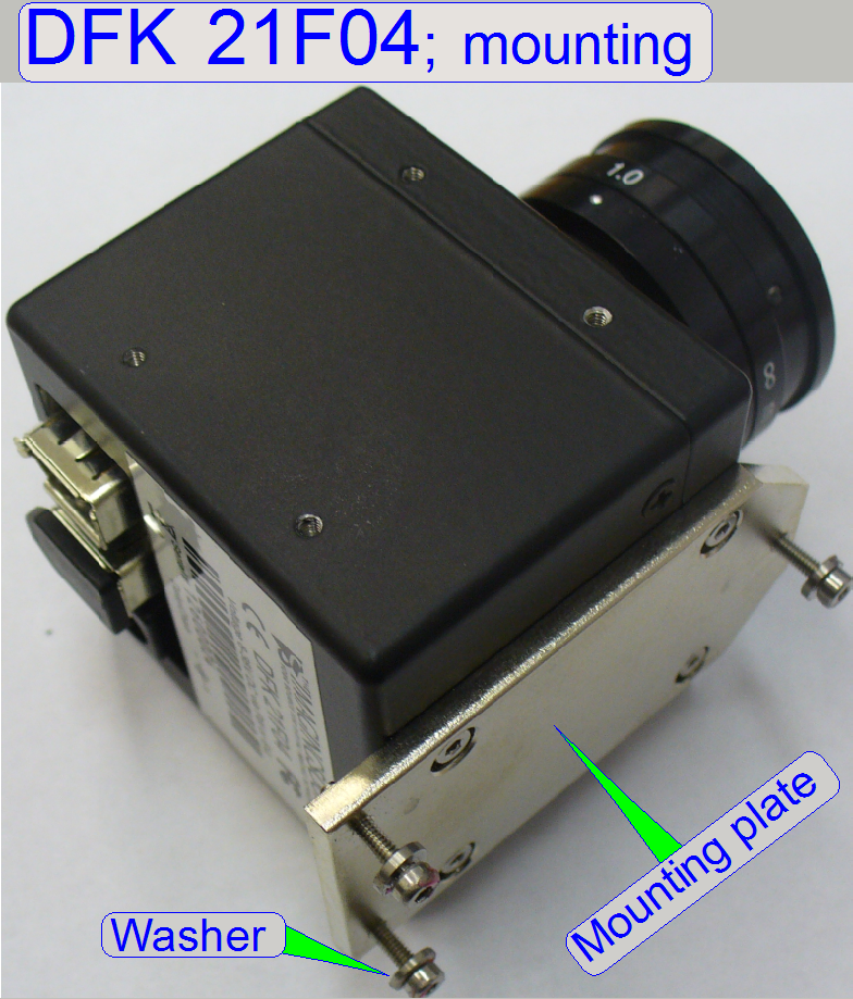 To make the preview camera position adjustable, a mounting
plate is used. The mounting plate is mounted to the horseshoe at three
positions, so a three-point-adjustment is realized.
To make the preview camera position adjustable, a mounting
plate is used. The mounting plate is mounted to the horseshoe at three
positions, so a three-point-adjustment is realized.
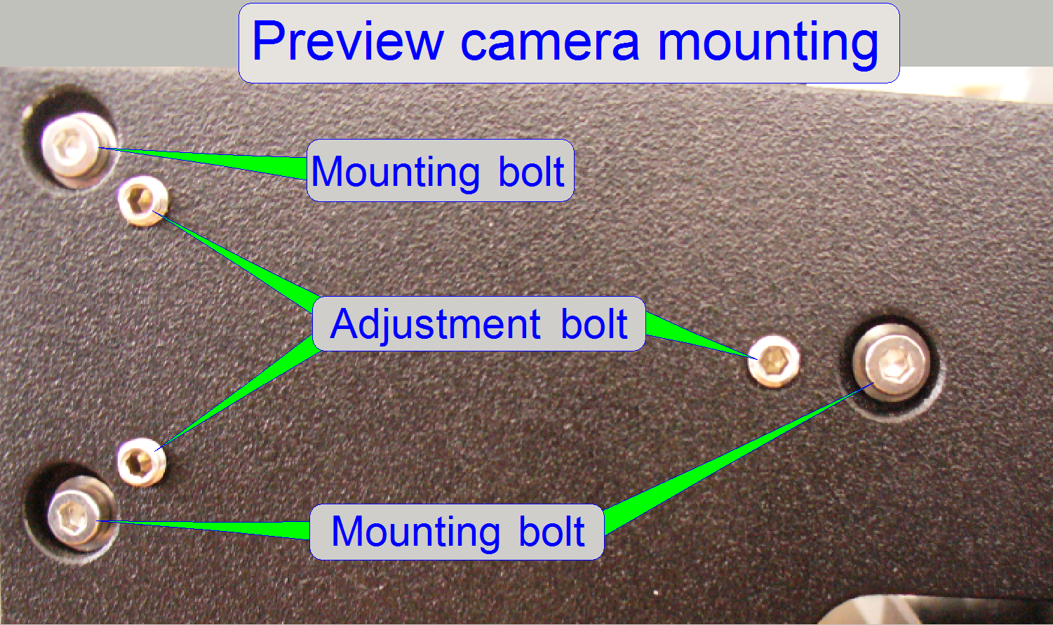
· With
the “Adjustment bolts” the plane of the preview camera will be defined and this
position is fixed by the “Mounting bolts”.
· By
adjusting the plane of the preview camera, the camera rotation angle will be
adjusted also!
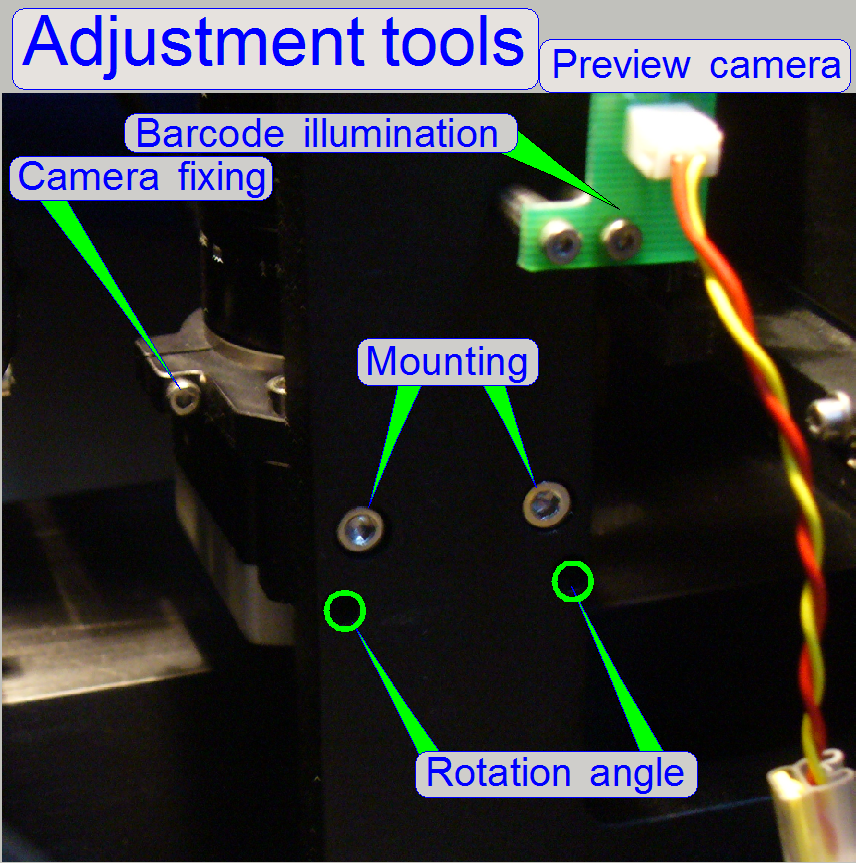
Camera VR magic
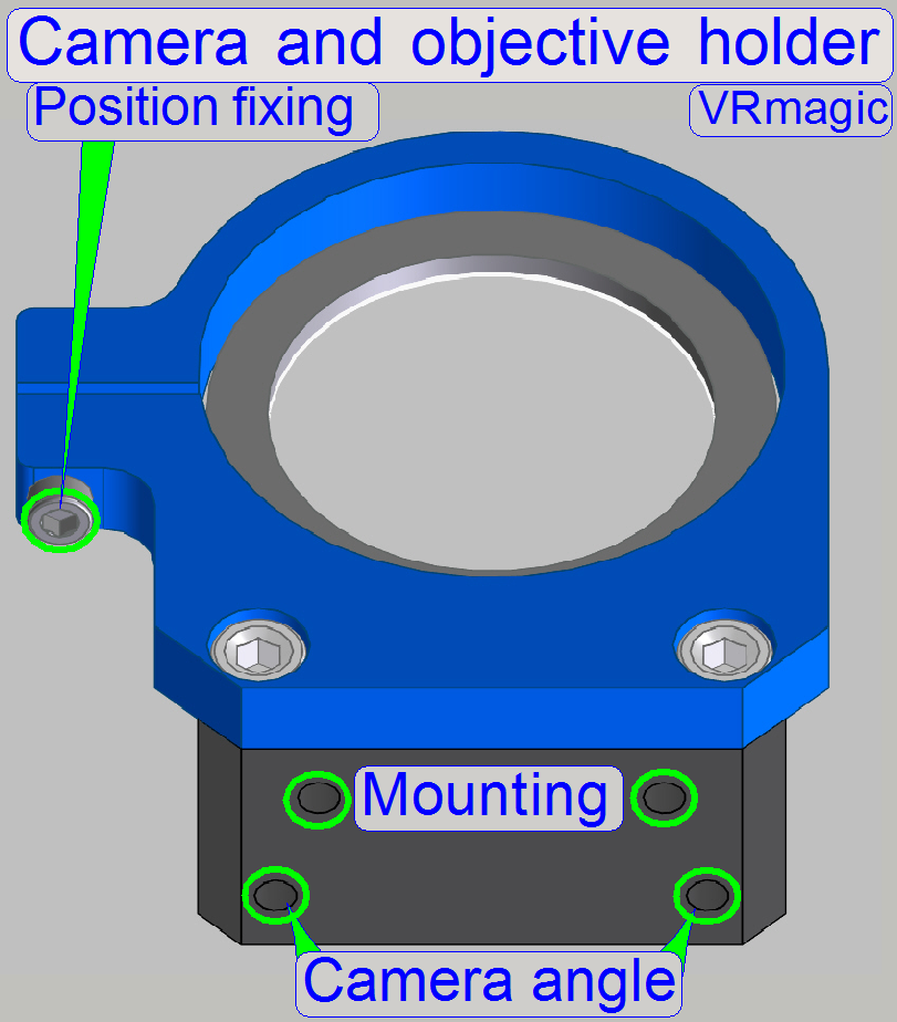
The preview objective and camera holder allows the
adjustment of the preview camera rotation angle in a limited range.
To adjust the camera rotation angle:
- Hold the camera from beneath (the rear of the camera) and loosen
the position fixing bolt a little bit until the camera becomes barely
moveable.
- By loosening one of the “Rotation angle” bolts and tightening the
opposite bolt, the rotation angle will be modified.
- If the correct camera rotation angle is found, tighten the
“Position fixing” bolt; further information can be found in the chapter “Adjust the
preview camera rotation angle”.
In the scanners
S_M_D the preview camera VRmc-8+ PRO can be used to create
the brightfield preview and also to capture the barcode since the
software version 1.16.
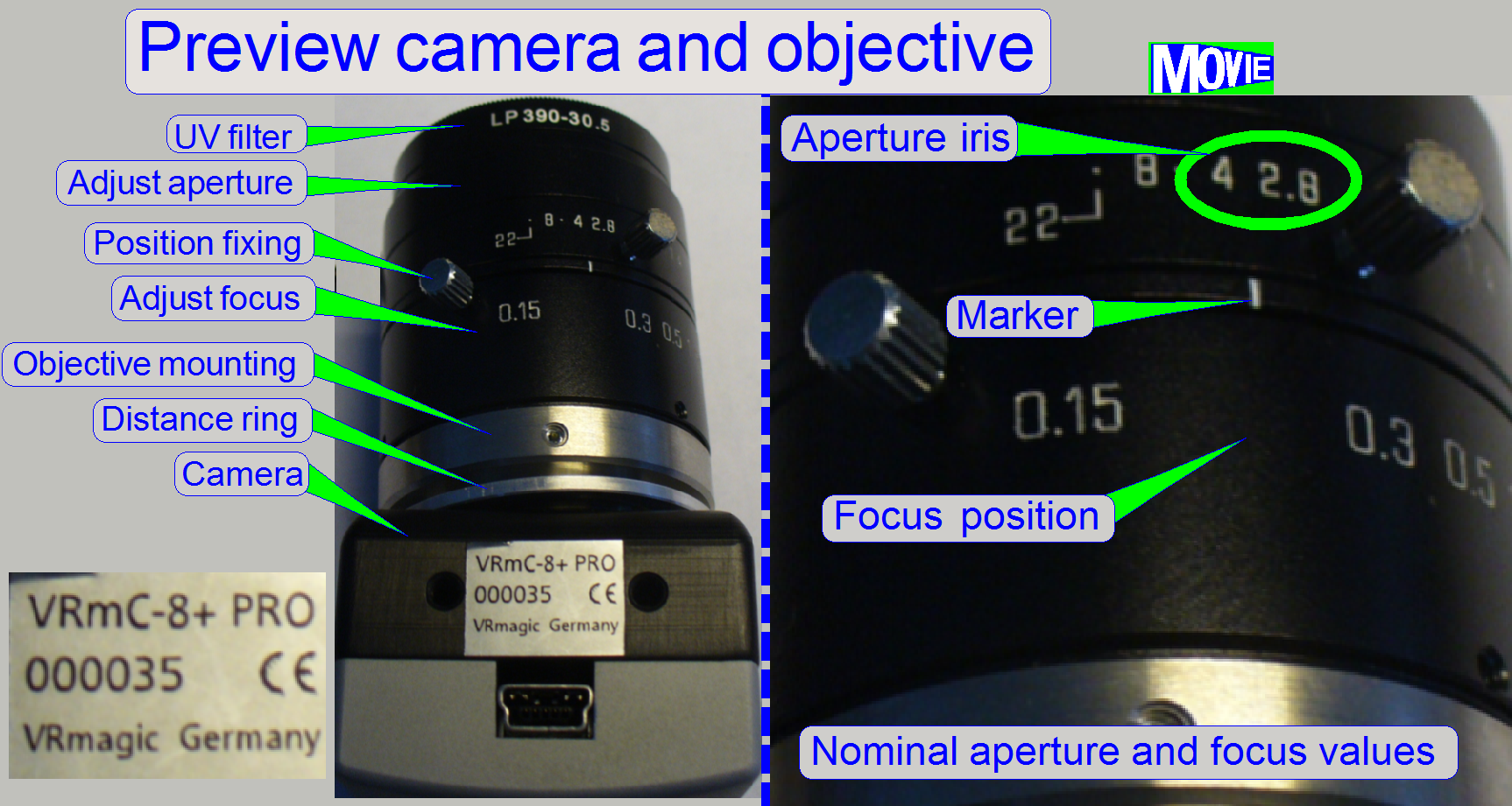
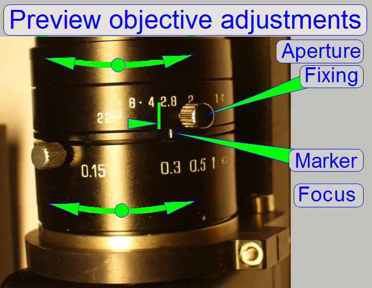
Because the camera has 2 different tasks, each kind of
image is illuminated from another illumination source and these are of a
different kind also, the adjustment of the aperture iris size and the focus
position of the objective are important.
- The distance ring has a thickness of 1.5 mm nominal.
- The shown
focus value is for information only, the real value will be found during
the preview calibration process.
- Set the value
of the aperture iris to 3.0.
Preview objective, TAMRON 23FM16SP
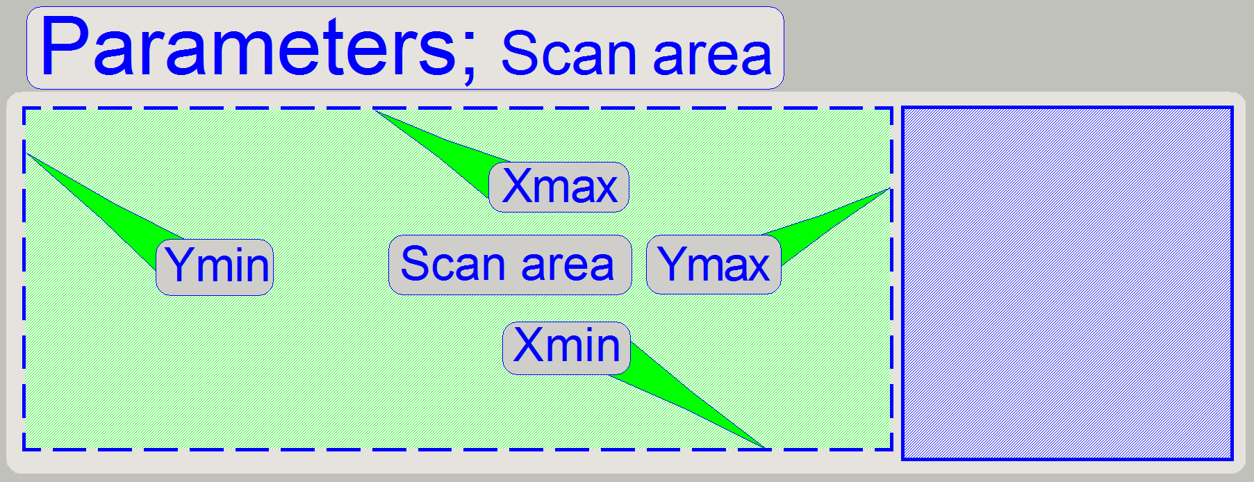
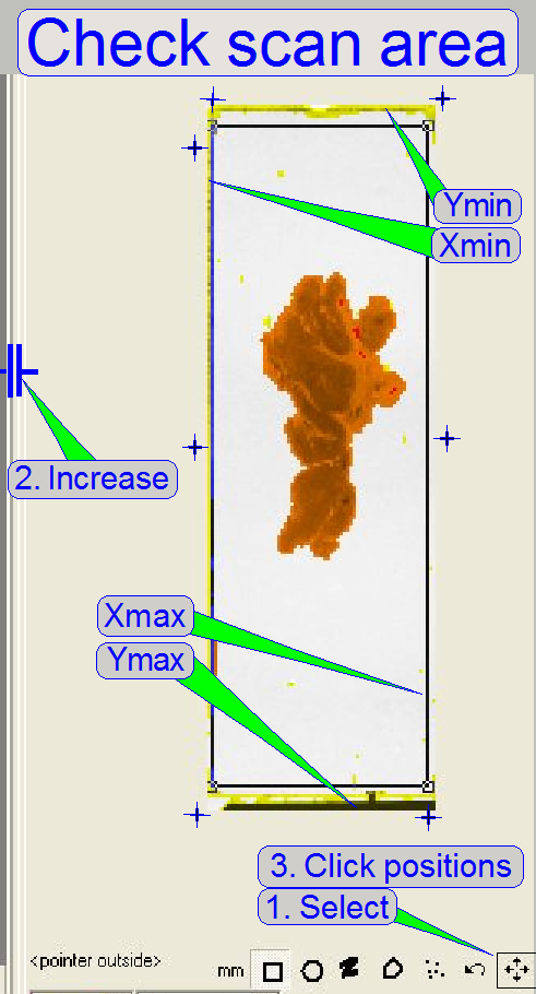
 The scan area
defines the part of the slide on which the tissue, scanned by the scan camera,
is expected to be. The entire scan area is captured by the preview
camera in three sections and is shown in the preview area of the program
SlideScanner.exe.
The scan area
defines the part of the slide on which the tissue, scanned by the scan camera,
is expected to be. The entire scan area is captured by the preview
camera in three sections and is shown in the preview area of the program
SlideScanner.exe.
The scan area is limited by the mechanical
construction of the specimen holder and should be defined as large as possible;
it is not defined in relation to the cover slip.
In all cases, the specimen holder should never be
touched by the focus pin or the objective! In other words, the scan area
is that area of the slide, on which the focus pin and the objective can be
moved seemingly during scanning the tissues, without touching the specimen
holder.
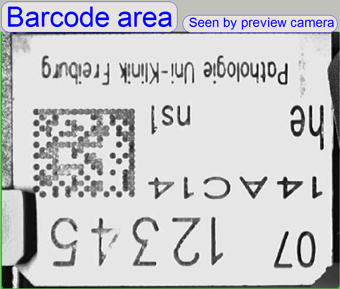 The
barcode area is situated beside the scan area and contains stickers or labels
with information about the tissue.
The
barcode area is situated beside the scan area and contains stickers or labels
with information about the tissue.
If the label contains a barcode, the analyzed and
decoded barcode can be used as file name for the scanned tissue.
· The
entire barcode area is captured by one field of view of the preview camera.
· To see
the information of the barcode area, it is illuminated by the barcode
illumination.
· An
evenly illuminated barcode area and a well adjusted focus of the preview
objective increase the readability of the barcode.
· The
correct position of the barcode area will be defined in the step 16 of the
preview calibration procedure.
Important
Stickers and labels should be placed only beside the
cover slip; the opposite surface from beneath is glass only. If labels are placed
on the opposite side also, the slide will not be hold correctly in the specimen
holder and “slant fields of view” are produced during the scan process; see
also: “Stage skew
check”.
![]() “Barcode illumination”; “Adjust the barcode
illumination”, “Step 16 of the preview
calibration procedure” and “Barcodes in practice”
“Barcode illumination”; “Adjust the barcode
illumination”, “Step 16 of the preview
calibration procedure” and “Barcodes in practice”
When shall I check or define the scan area?
- If the X-Y-stage was exchanged
- If the parallelogram was adjusted
- If any modifications on the specimen holder or its mounting was
taken
- If the scan area of the slide is too small or too much.
The scan area is defined during the system integration
procedure.
If the scan area was modified, the steps and checks,
described under “Adjust
the pixel of the preview camera to the field of view of the scan camera” must be executed.
The scan area values may vary from scanner
to scanner (depending on the specimen holder and parallelogram adjustment and
mechanical tolerances); so the scan area has to be defined for each
scanner separately.
In all cases, the scan area values of X-min,
X-max, Y-min and Y-max are set just before the focus pin or the objective
touches the specimen holder; the accuracy of the limits is 100 steps.
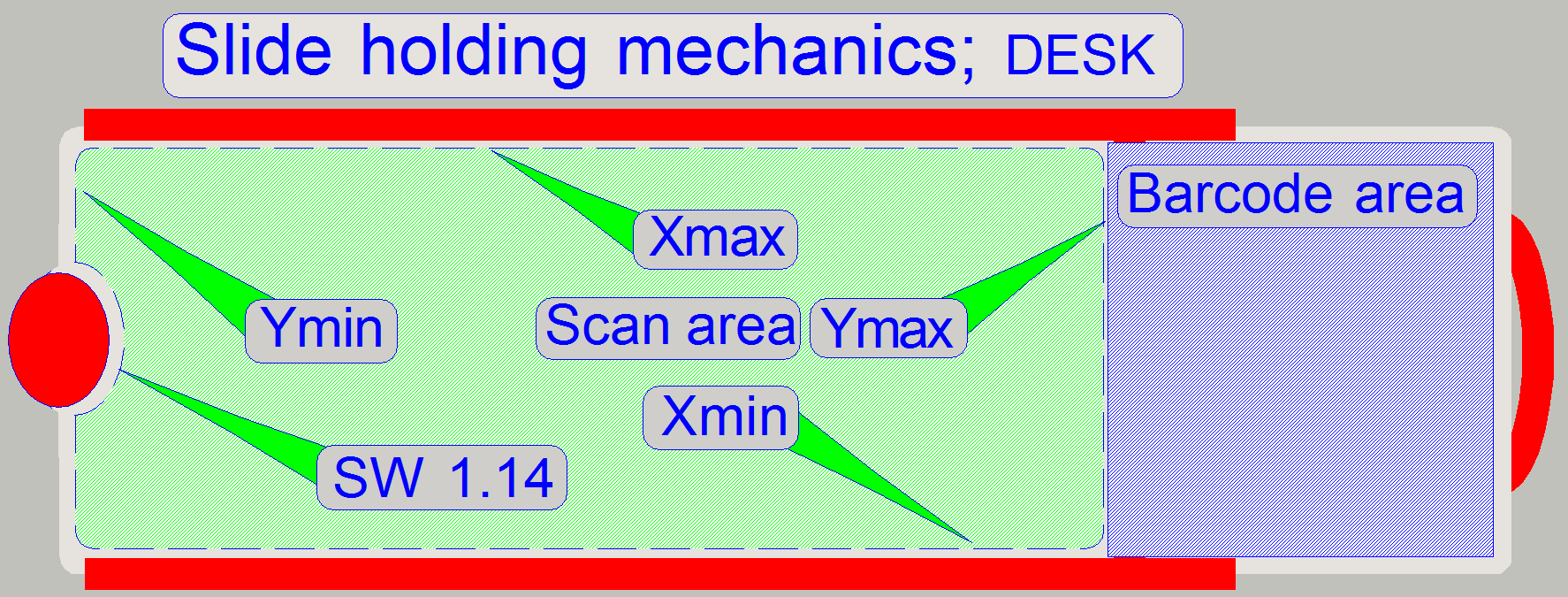
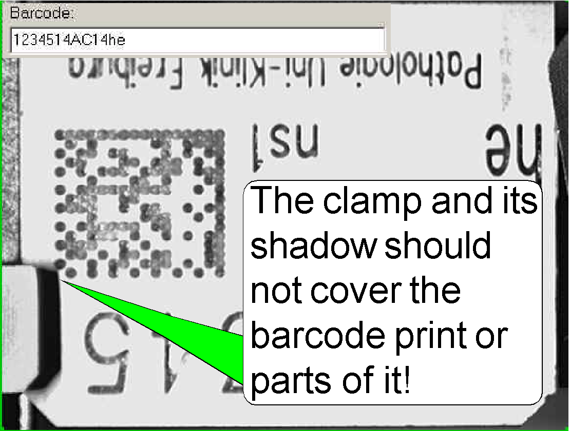
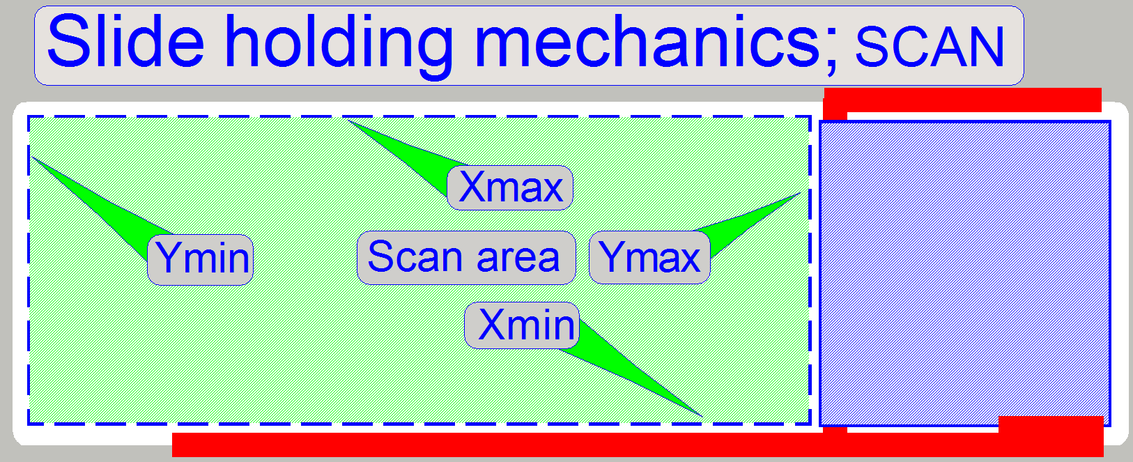 The
slide is hold by the specimen holder on the longer, lower edge and with a slide
clamp on its upper edge, on the barcode area; see the red lines on the right.
As you can see, the definition of the limits X-min and Y-max are critical.
The
slide is hold by the specimen holder on the longer, lower edge and with a slide
clamp on its upper edge, on the barcode area; see the red lines on the right.
As you can see, the definition of the limits X-min and Y-max are critical.
X-max and Y-min are given by the maximal usable slide
size and are not critical; they could be the slide edge of the largest, allowed
slide dimensions.
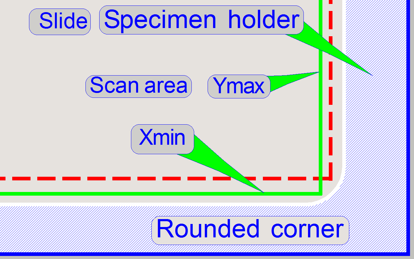 Because
there is a rounded corner on the specimen holder as shown on the right (X-min
and Y-max corner), there are two possibilities to define
the scan area, shown with the red and green lines.
Because
there is a rounded corner on the specimen holder as shown on the right (X-min
and Y-max corner), there are two possibilities to define
the scan area, shown with the red and green lines.
The Y-max value
can be more decreased (the scan area will be shortened in
Y-direction) and the value of X-min can be decreased (the scan area
will be larger in X-direction). Technically, both solutions can be accepted,
but in practice, the users prefer the solution as shown with the green lines.
The difference between both solutions is more hundred steps in each direction.
Please take this into account if you are defining the scan area.
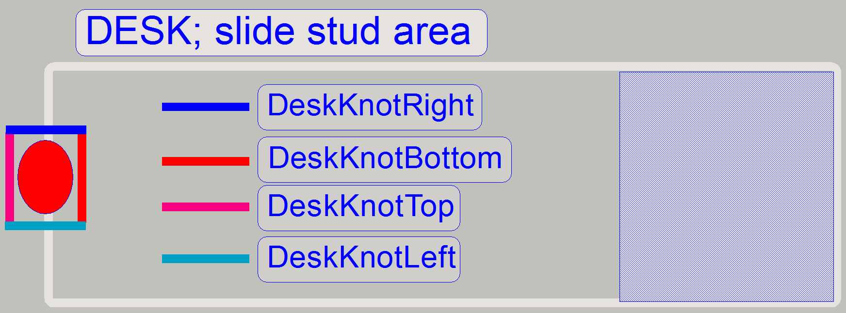
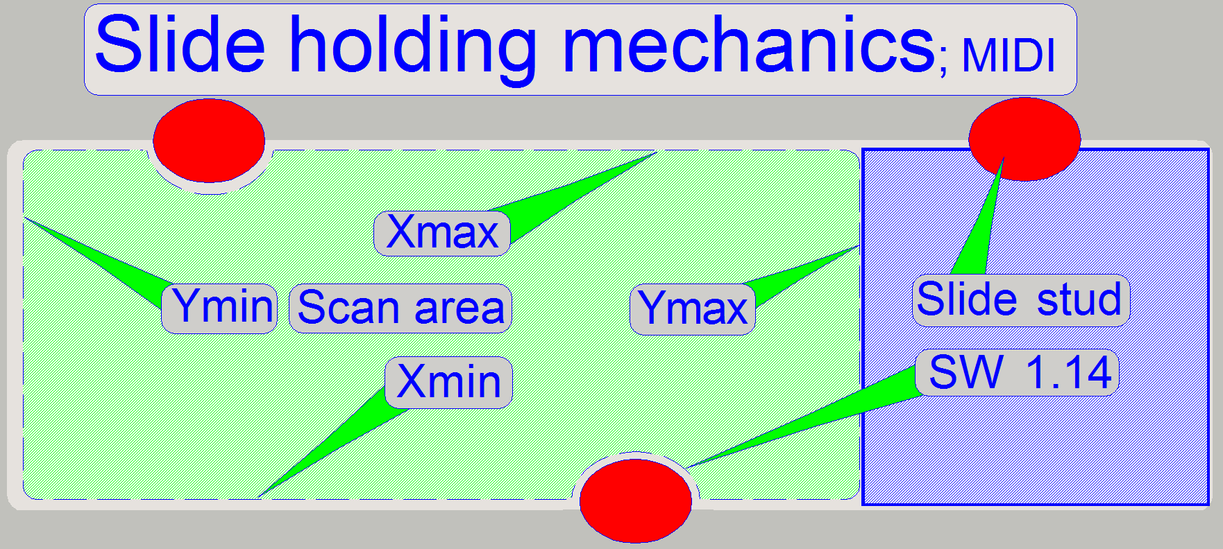 The
slide is held in the specimen holder with the help of three slide studs,
situated on the longer edges as shown.
The
slide is held in the specimen holder with the help of three slide studs,
situated on the longer edges as shown.
The surrounding of the slide stud is left out
automatically from the scan process since the software version 1.14 and needs
not more to be excluded manually from the scan area (until software version
1.16).
·
During movements with the service program,
please do never touch the slide stud with the focus pin or the objective!
Since the software version 1.16
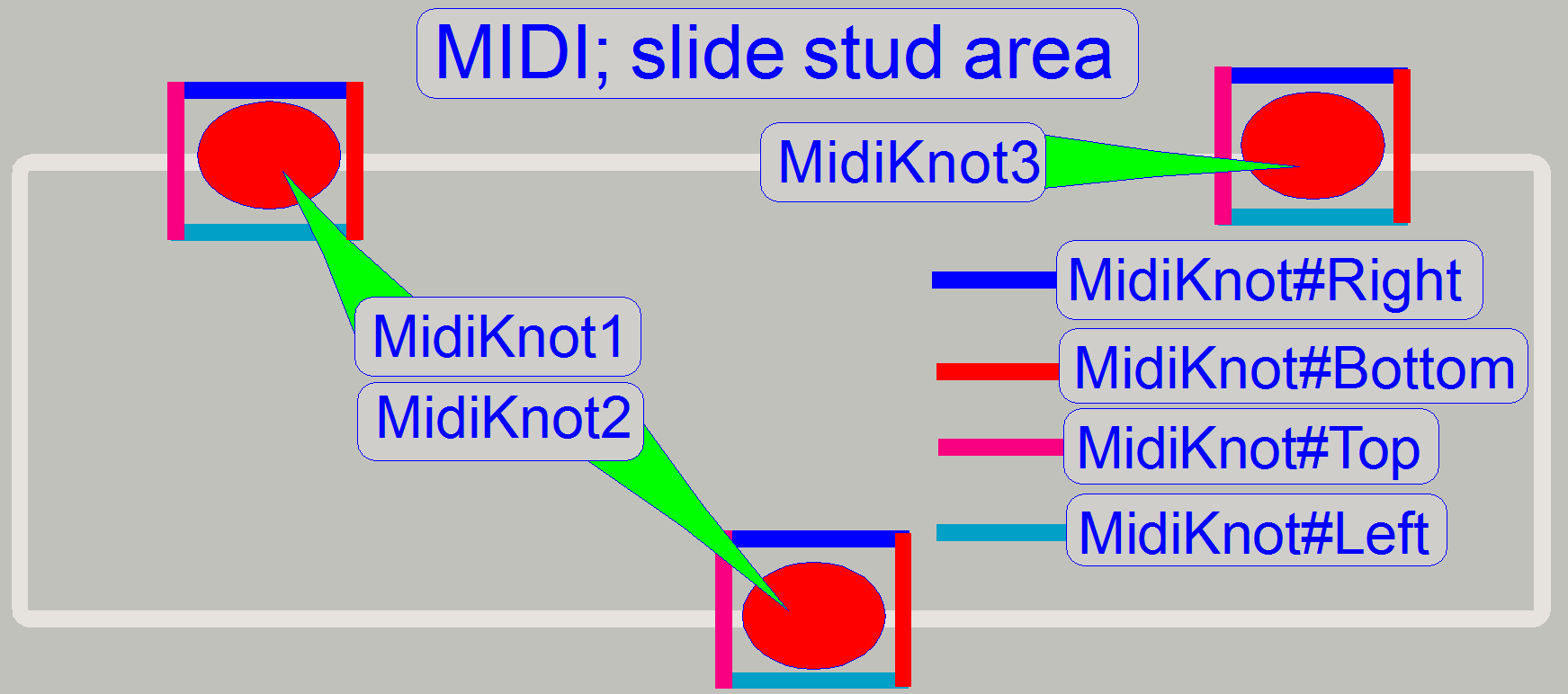 To
avoid, that the objective may touch the slide stud, the area of the slide studs
is defined explicitly; new parameters are implemented in the section
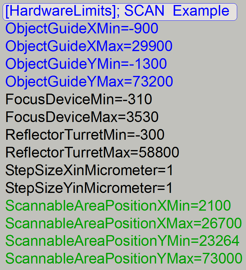
[HardwareLimits] of the file “MicroscopeConfiguration.ini”.
To
avoid, that the objective may touch the slide stud, the area of the slide studs
is defined explicitly; new parameters are implemented in the section
[HardwareLimits] of the file “MicroscopeConfiguration.ini”.
· Move
the stage to the positions “Knot#Left”, “Knot#Right”, “Knot#Top” and
“Knot#Bottom” just before the objective would touch the slide stud and
actualize the value of the appropriate parameter; the accuracy should be 100
steps.
· If the
objective was changed from 20x to 40x the slide stud area has to be defined
again.
· Because
the objective will never reach the slide stud “MidiKnot3”, these values should
be left unchanged.
· Please
take this into account, if software is upgraded from an earlier version to the
version 1.16 or higher!
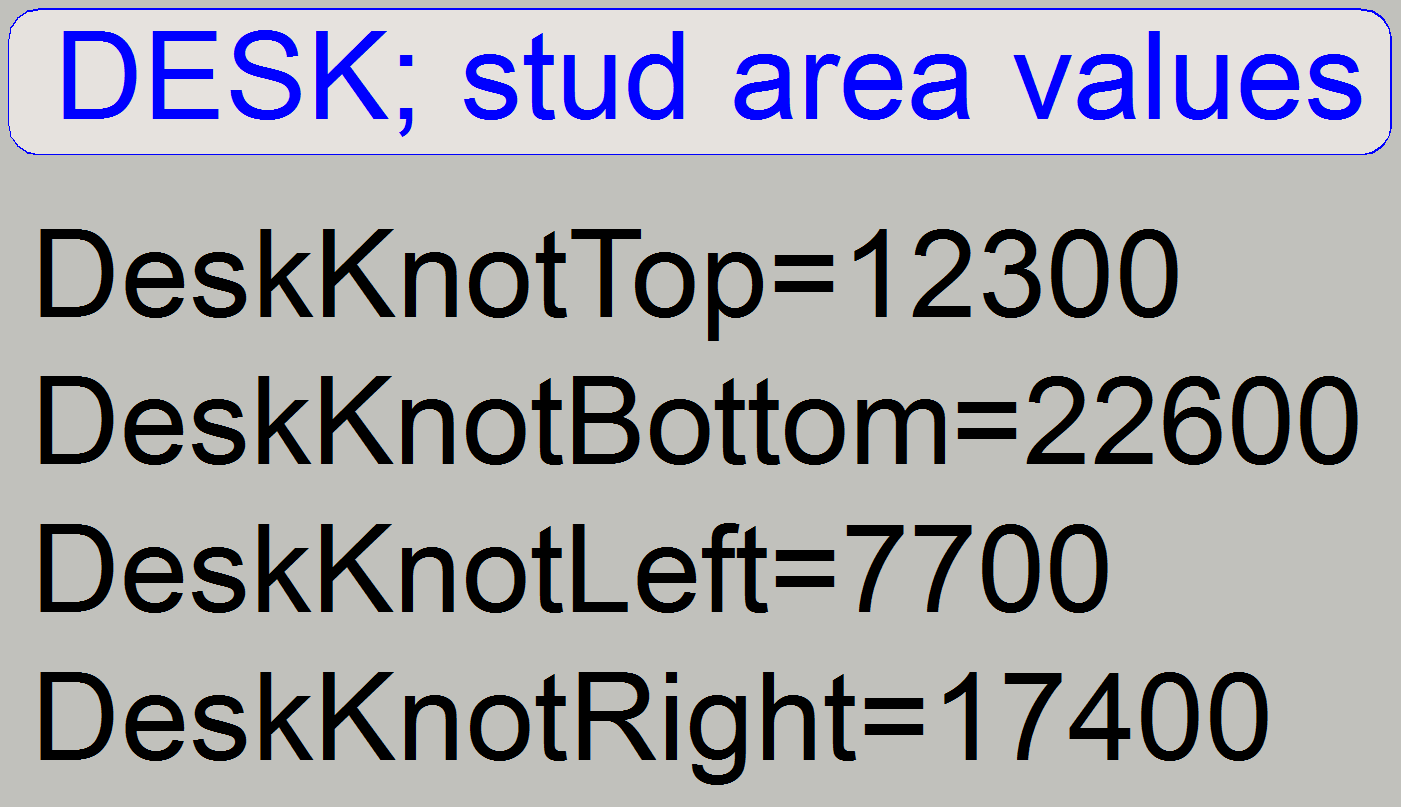
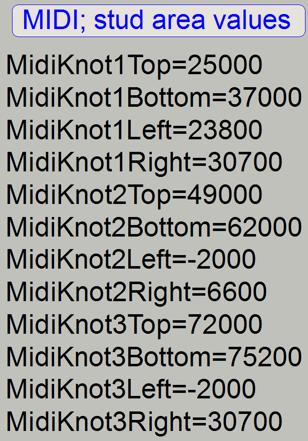 The
values are found at the end of the section [HardwareLimits] in the file
“MicroscopeConfiguration.ini”.
The
values are found at the end of the section [HardwareLimits] in the file
“MicroscopeConfiguration.ini”.
· The values, shown on the right are for
demonstration only and should not be used
· The defined areas are excluded from the scan area!
· Because
the objective will never reach the slide stud “MidiKnot3”, these values should
be left unchanged.
· The
path of the file “MicroscopeConfiguration.ini”, since the version 1.15 is:
C:\ProgramData\3DHISTECH\SlideScanner\MicroscopeConfiguration.ini
Remark
Because the values are always checked before executing
the number of steps to go in the scan program, the value of “-2000 steps” will
be cut to the value of the hardware limit!
The
stud has a size of about
Top to bottom: 12mm
Left to right: 8mm

 The
slide is hold in the specimen holder by the help of one slide stud on the shorter,
inner edge and by the lock handle on the outer, shorter edge. Furthermore,
along the longer edges of the slide there are leading rails situated to lead
the slide during slide insertion. All this facts should be taken into account
if the scan area is defined. The surrounding of the slide stud is left out
automatically from the scan process since the software version 1.14 and needs
not to be excluded manually from the scan area (until software version 1.16).
If you are working with the service program take care of the focus pin and the
objective.
The
slide is hold in the specimen holder by the help of one slide stud on the shorter,
inner edge and by the lock handle on the outer, shorter edge. Furthermore,
along the longer edges of the slide there are leading rails situated to lead
the slide during slide insertion. All this facts should be taken into account
if the scan area is defined. The surrounding of the slide stud is left out
automatically from the scan process since the software version 1.14 and needs
not to be excluded manually from the scan area (until software version 1.16).
If you are working with the service program take care of the focus pin and the
objective.
·
During movements with the service program,
please do never touch the slide stud with the focus pin or the objective!
Since the software version 1.16
 To avoid,
that the objective may touch the slide stud, the area of the slide stud is
defined explicitly; new parameters are implemented in the section
[HardwareLimits] of the file “MicroscopeConfiguration.ini”.
To avoid,
that the objective may touch the slide stud, the area of the slide stud is
defined explicitly; new parameters are implemented in the section
[HardwareLimits] of the file “MicroscopeConfiguration.ini”.
· Move
the stage to the positions “KnotLeft”, “KnotRight”, “KnotTop” and “KnotBottom”
just before the objective would touch the slide stud and actualize the value of
the appropriate parameter; the accuracy should be 100 steps.
· If the
objective was changed from 20x to 40x the slide stud area has to be defined
again.
· Please
take this into account, if software is upgraded from an earlier version to the
version 1.16!
The values are found at the end of the section
[HardwareLimits] in the file “MicroscopeConfiguration.ini”.
· The values, shown on the right are for
demonstration only and should not be used!
· The defined area is excluded from the scan area!
· The
path of the file “MicroscopeConfiguration.ini”, since the version 1.15 is:
C:\ProgramData\3DHISTECH\SlideScanner\MicroscopeConfiguration.ini
Check
the found limit position
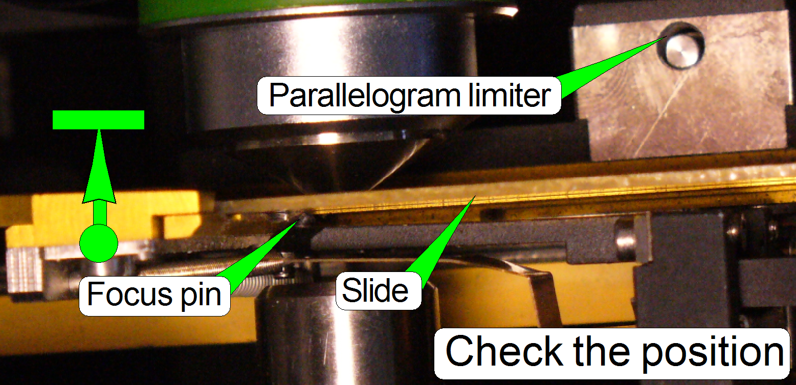 To decide, the focus pin is whether on glass
or metal is touched, the following actions can help.
To decide, the focus pin is whether on glass
or metal is touched, the following actions can help.
· Move
the focus pin to the focus position of 800steps.
· Move
the specimen holder with the finger nail carefully to the left
by about 0.5 mm maximal so, that the mechanical preload of the
specimen holder is overridden; the slide is even disconnected from the focus
pin.
· Release
the specimen holder abruptly.
· The behavior
and the sound can be used to decide the focus pin is whether on glass or on
metal.
· To use
this method effectively, try this some times on different, non critical and
critical positions on the slide; listening and memorize the sound for glass.
The following “flow chart” describes the steps for
Pannoramic SCAN especially. The steps for
· This procedure
assumes that the hardware limits of the X-Y-stage unit are already defined.
· The
path of the file “MicroscopeConfiguration.ini”, in the version 1.14 is:
C:\ Documents and Settings\All Users\Application
Data\3DHISTECH\SlideScanner\ MicroscopeConfiguration.ini
· The
path of the file “MicroscopeConfiguration.ini”, since the version 1.15 is:
C:\ProgramData\3DHISTECH\SlideScanner\MicroscopeConfiguration.ini
·
The scan area values to
be used are set just before the focus pin or the objective touches the specimen
holder mechanics. The accuracy of the limits is 100 steps.
1.
Insert a medium large slide or the Test slide #2.
2.
Start the Mservice.exe program, Low level service
part.
3.
Go forward to 26000 steps in +X direction.
4.
Press Home1 then Home2 for the Y-stepper motor.
5.
Press Home1 then Home2 for the X-stepper motor.
6.
Go to position X=4000 steps.
7.
 To find the
“rounded” corner of the specimen holder, go to the position Y-max. This
position is nearly 74000 steps or somewhat below. The real value can be found
in the section [HardwareLimits]. If the specimen holder is touched by the focus
pin, move the Y-stepper backward by 100 steps until the specimen holder is not
touched and memorize this number of steps in Y-direction. If necessary, go to
Y-Home1,2 for the Y-stepper motor and forward again to the memorized position
(if steps where lost).
To find the
“rounded” corner of the specimen holder, go to the position Y-max. This
position is nearly 74000 steps or somewhat below. The real value can be found
in the section [HardwareLimits]. If the specimen holder is touched by the focus
pin, move the Y-stepper backward by 100 steps until the specimen holder is not
touched and memorize this number of steps in Y-direction. If necessary, go to
Y-Home1,2 for the Y-stepper motor and forward again to the memorized position
(if steps where lost).
8.
To find the lower edge of the “rounded” corner of the
specimen holder, decrease the number of steps by
9.
After each movement of the specimen holder (either in
X- or Y-direction) check the limit as described in the paragraph above “To
check the found limit position”.
10. Decrease / increase
the number of steps in the X-direction and the Y-direction until the correct
corner point is found (see also “The physical construction of the specimen
holders”).
11. If the corner
point is found without touching the specimen holder and without lost steps
update the parameter “ScannableAreaPositionXmin” with the found value of steps
in X-direction and the value of the parameter “ScannableAreaPositionYmax” with
the found value of steps in Y-direction in the file
“MicroscopeConfiguration.ini” section [HardwareLimits] and save the file.
12. With the 3200
steps button go backward in -Y-direction (along the specimen holder side,
defined by the parameter X-min) until the inner edge of the slide is reached
and check after each click the correctness of the value for the parameter
“ScannableAreaPositionXmin” as described in the paragraph above “To check the
found limit position”. Collision with the specimen holder must not occur! Do
the step 12 logically on each already defined edge.
13. To define the
values for the parameters “ScannableAreaPositionXmax” and
“ScannableAreaPositionYmin”, move the specimen holder into the opposite corner
and repeat the flow chart from step 3 logically. In step 6 start with the
position X = 24000 and in step 7 use the value of Y=23000 steps as a starting
point.
14. If the corner
point is found without touching the specimen holder and without lost steps
update the parameter “ScannableAreaPositionXmax” with the found value of steps
in X-direction and the value of the parameter “ScannableAreaPositionYmin” with
the found value of steps in Y-direction in the file
“MicroscopeConfiguration.ini” section [HardwareLimits] and save the file.
15. Repeat step 12
logically with all four edges of the defined scan area. If anywhere collision
occurs, define the appropriate parameter value again and actualize it in the
file “MicroscopeConfiguration.ini” section [HardwareLimits] and save the file.
Define
the slide stud area
· The values of the
slide stud area are defined just before the objective would touch the slide
stud; please use an accuracy of 100 steps.
·
To define the values, please use the same technique as
described above, in the chapter “Define the scan area”.
· The defined areas are excluded from the scan area!
· Because
the objective will never reach the slide stud “MidiKnot3”, these values should
be left unchanged.
· See
also “Scan area and specimen
holders”, “PMIDI” and “PDESK”
Adjustments of the
preview unit
The
adjustment of the preview unit includes:
- Adjust the aperture
iris size of the preview objective ˙(Tamron objective only)
- Adjust
the focus position of the preview objective
- Adjust
the preview camera rotation angle
- Execute
the preview calibration procedure
- Adjust the
preview pixel to the field of view of the scan camera
- Save the configuration file into the EEPROM.
- Adjust the
barcode illumination
- Check barcode reading
Prerequisites for
the BF preview calibration
The success of the preview calibration procedure is
bound to the following components and parameter values:
- Driver of the preview camera is installed.
- Hardware limits of the X-, Y- and focus unit are defined.
- Home position of the turret unit is already adjusted; the first
filter position is defined.
- Brightfield preview illumination was checked with the service
program and can be switched on / off.
 When shall I do a
preview calibration?
When shall I do a
preview calibration?
- If the focus position of the preview objective was altered.
- If the preview camera was loosened, dismounted, changed.
- If adjustments are done on the parallelogram or the specimen holder
or the X-Y-stage was exchanged.
- If the scanned area of the tissue is different from the selected
area in the preview window.
Steps
of the preview calibration procedure
- Set the aperture
of the preview objective (Tamron objective only).
- Start the
preview calibration procedure
3.
Adjust the focus
of the preview objective.
4.
Adjust the
rotation angle of the preview camera.
- Adjust the objective position
of the 20x scanner objective (if not adjusted previously).
- Define the barcode area
Attention: If you adjusted the
mechanical mounting of preview camera or you adjusted the focus of preview
camera, a preview calibration should be done again. Otherwise, the scanned area
of tissue will be different from the shown area in the preview window.
To adjust the preview camera you need a
Start the service program “SlideScannerService.exe”
and the option “Preview calibration”.
Adjust the preview camera position
Bring the Y-stepper in the position of -800 steps if the hardware limit
of the Y-min position allows it. This value is suggested for all three scanner
types. Set the X-stepper value to 28000.
The preview camera mounting is realized with three bolt pairs. The
adjustment bolts define the distance of the camera holding plate from the base.
The mounting bolts fix this distance.
· By loosening the
mounting and the adjustment bolts the preview camera becomes movable.
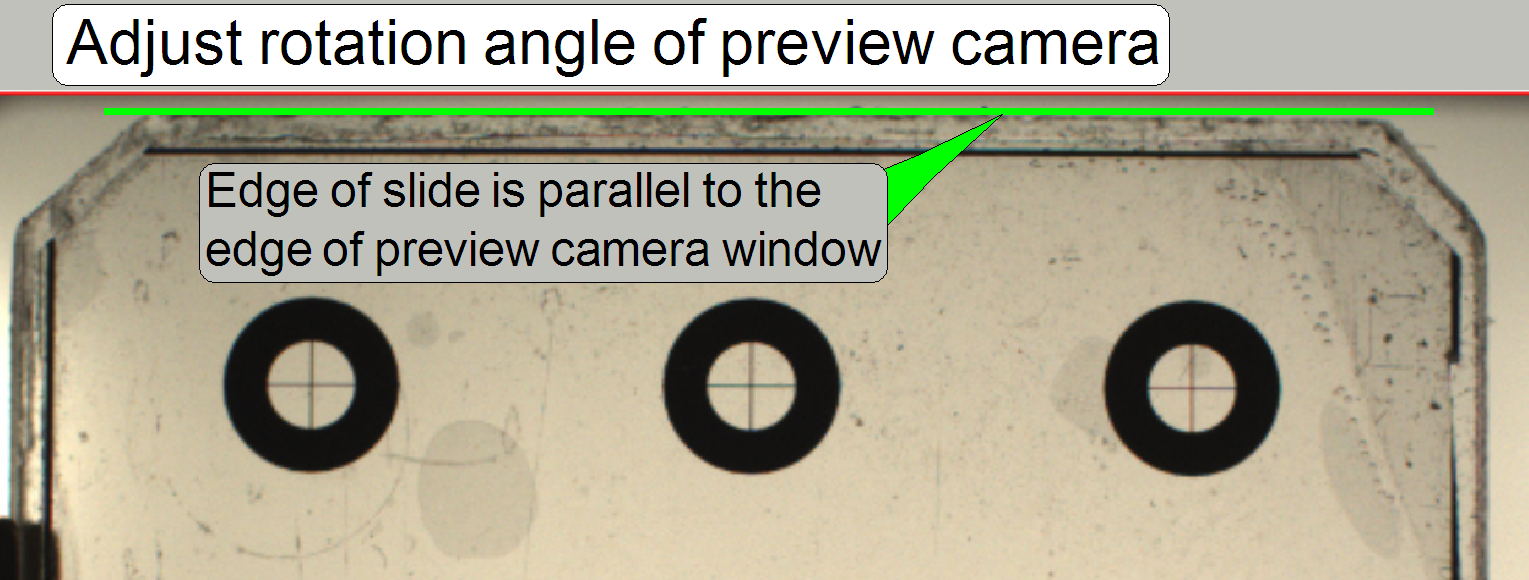 Adjust the
top slide edge parallel to the edge of the live view preview camera window
(in reality, the preview camera image will be rotated). The camera
rotation angle is acceptable if the top of the slide edge is parallel to
the top edge of the preview camera window; an acceptable deviation is
often less then 0.5 degrees.
Adjust the
top slide edge parallel to the edge of the live view preview camera window
(in reality, the preview camera image will be rotated). The camera
rotation angle is acceptable if the top of the slide edge is parallel to
the top edge of the preview camera window; an acceptable deviation is
often less then 0.5 degrees.
After tightening the mounting
bolts and adjustment bolts, any kind of shadow should be minimized and the top
of the slide should not be cut too much.
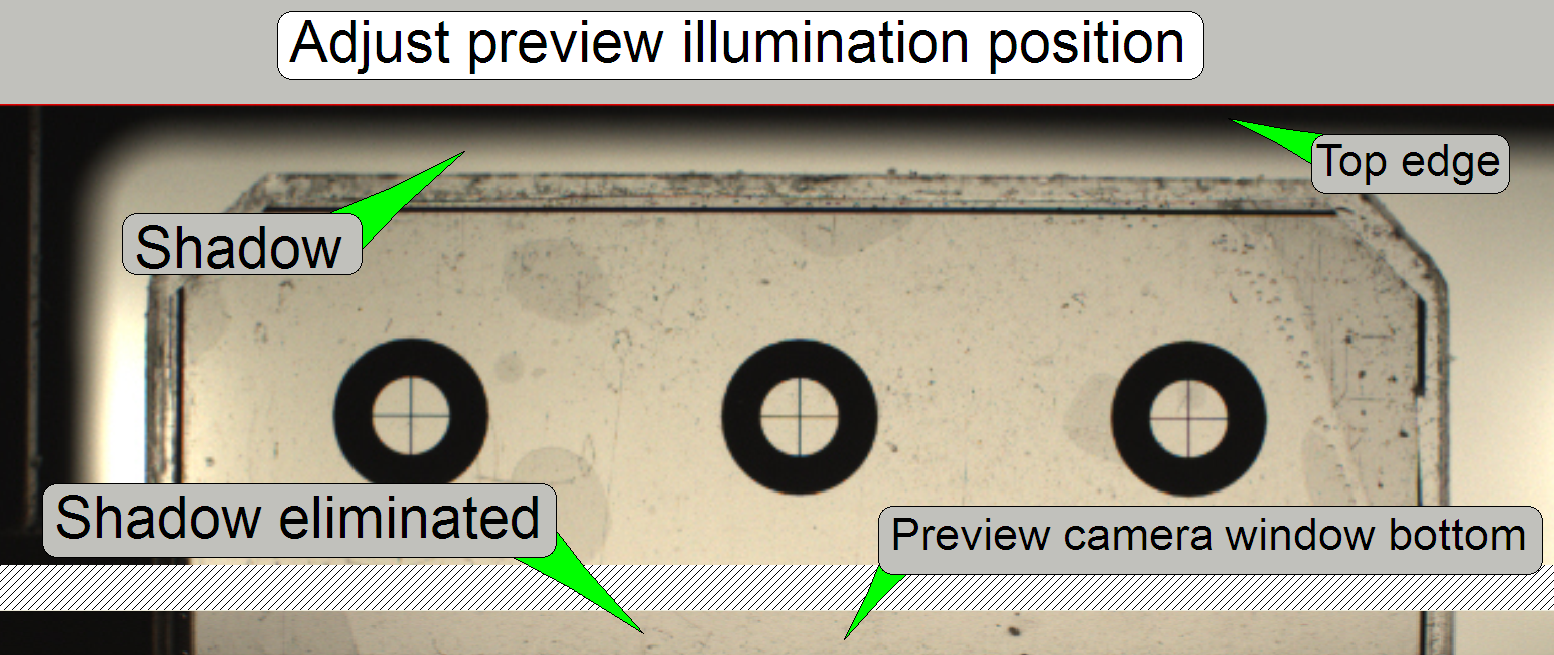 Remark: The shadow on
the top edge of the preview will be cut later, during the preview calibration procedure;
“Step 2”.
Remark: The shadow on
the top edge of the preview will be cut later, during the preview calibration procedure;
“Step 2”.
· On the
slide bottom any kind of shadow must be eliminated!
After inserting the calibration slide the live view of preview camera is
shown in the camera window.
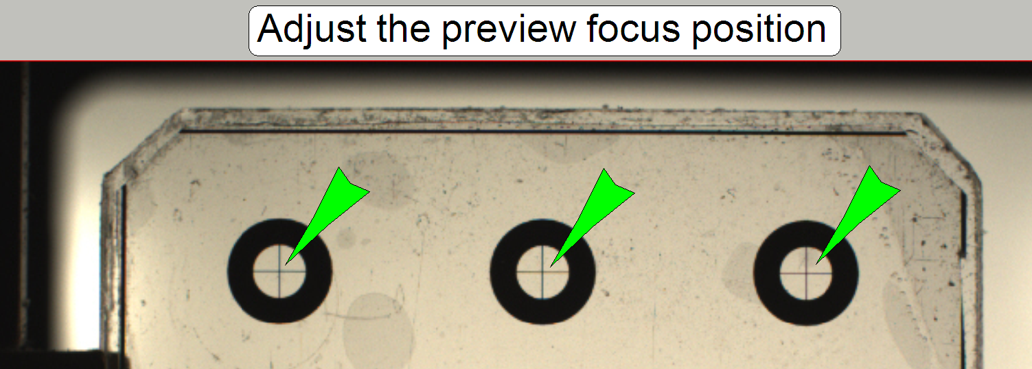
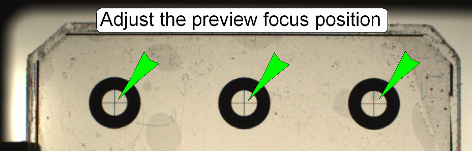
 Use the crosses of
the calibration slide to adjust the focus of the preview camera objective.
After starting the preview procedure this focus position should never be
changed, otherwise, the preview calibration procedure has to be done again.
Use the crosses of
the calibration slide to adjust the focus of the preview camera objective.
After starting the preview procedure this focus position should never be
changed, otherwise, the preview calibration procedure has to be done again.
 Use
the crosses of the calibration slide to adjust the focus of the preview camera
objective.
Use
the crosses of the calibration slide to adjust the focus of the preview camera
objective.
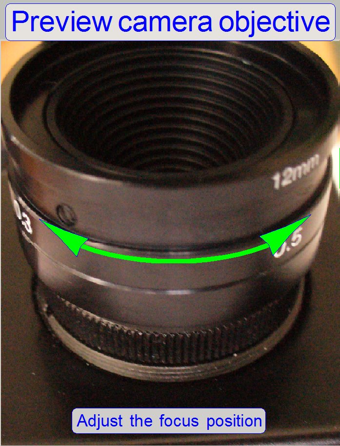
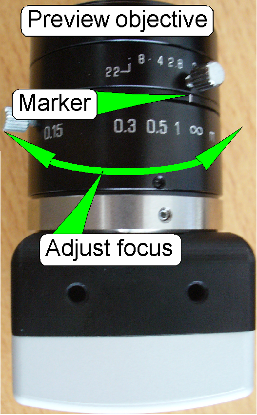
- Loosen the fixing bolt of the focus part of the preview objective,
adjust the focus position so, that the centers of the circles are in focus
and then tighten the fixing bolt.
Set
aperture; Tamron
- Loosen the aperture fixing bolt, set the aperture to a value of 3.0
and tighten the fixing bolt.
Remark: To
adjust the aperture of the preview objective the focus unit should be removed
or the horseshoe can be dismounted.
Adjust the focus position; Tamron
Start the service program and select the option
“Preview calibration”.
Load the preview slide in “Manual” or “Automatic” mode; select the
appropriate option.
- The manual mode should be selected if the magazine unit is removed.
- The automatic mode should be used if the magazine and slide loading
procedure is done by the magazine unit and the slide loader.
See also: “Insert or
remove a slide manually”
After inserting the preview calibration slide (Test slide #2) the live view of the
preview camera is shown in the camera window.
 Use
the crosses of the calibration slide to adjust the focus of the preview camera
objective.
Use
the crosses of the calibration slide to adjust the focus of the preview camera
objective.
- Loosen the fixing bolt of the focus part of the preview objective,
adjust the focus position so, that the centers of the circles are in focus
and then tighten the fixing bolt.
Adjust the camera position; VRm
Bring the Y-stepper motor in the position where the
edge of the slide is near to the top edge of the preview window. Set the
X-stepper value to 28800.
- Loosen the brightfield preview illumination adjustment and
fixing bolts a little bit and remove the shadow from the top edge of the
live view window, then tighten the bolts carefully; they are driven into
plastic!
Remark: This
adjustment is done only to see the top edge of the slide as sharp as possible;
so the camera rotation angle can be adjusted properly.
To loosen the camera and
objective holder you need a 1.5 mm hex wrench.
- Hold the camera from beneath (the rear of the camera) and loosen
the camera holder fixing bolt a little bit until the camera becomes barely
moveable.
By loosening one of the “Rotation angle” bolts and
tightening the opposite bolt, the rotation angle will be modified; see also
“Preview objective and camera holder” above.
- Adjust the
top slide edge parallel to the edge of the live view preview camera window
(in reality, the preview camera image will be rotated). The camera
rotation angle is acceptable if the top of the slide edge is parallel to
the top edge of the preview camera window; an acceptable deviation is
often less then 0.5 degrees.
Remark: The shadow on the
top edge of the preview will be cut later, during the preview calibration
procedure; “Step 2”.
· On the
slide bottom any kind of shadow must be eliminated!
· Modify
the preview illumination position, until the requirement is fulfilled; check
also the correct preview camera position!
The preview calibration part of
the SlideScannerService program adjusts the pixel view of the preview
camera to the FOV (Field of view) of the scan camera, because both cameras are
physically in distance to each other.
The preview calibration includes:
1. Defining
the position of the preview camera’s pixel and the scan camera’s FOV.
2. Adjusts
the pixel position of the preview camera to the FOV position of the scan
camera.
3. The
preview camera takes three images from the slide. The parameters for assembling
the three parts are defined in the preview calibration process.
4. Defining
the barcode area.
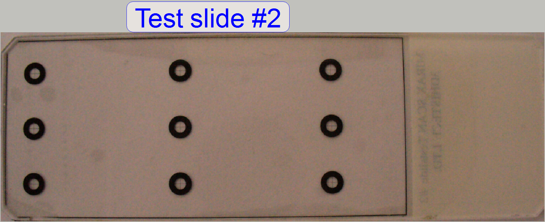
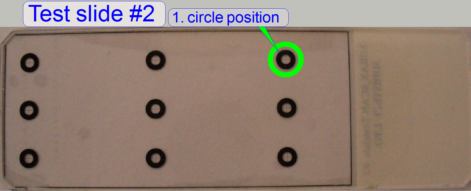
The calibration slide (Test slide #2) defines positions
inside the scan area with circles containing a cross. The centers of
the crosses are marker positions for the preview camera and the scan camera
also.
Calibration
program tools
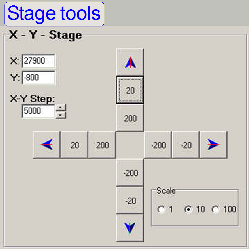
X- Y- Stage area
X: steps Actual position
of the X-stepper motor
Y: steps Actual position
of the Y-stepper motor
X-Y step: 5000 Step range
for the blue arrow buttons
Scale 1, 10, 100
The step number of the numbered buttons can be varied
between at least 2 steps (Scale=1) and 2000 steps (Scale=100). This way, you
can find desired positions quicker.
· With a
right click on a numbered or arrow button the original direction will be
inverted. The stepper motor is moved with the number of steps written in the
button but the movement occurs in opposite direction.
Focus
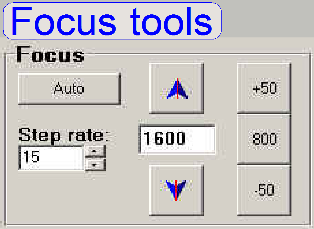 Auto: Finds
the focus position via the auto focus function, realized in the program
SlideScanner.exe.
Auto: Finds
the focus position via the auto focus function, realized in the program
SlideScanner.exe.
1600: Actual focus position field
Step rate: Step
rate for the blue arrows. By right clicking on an arrow button (or a numbered
button also), the original direction will be inverted by the actual number of
steps, given in the field “Step rate”.
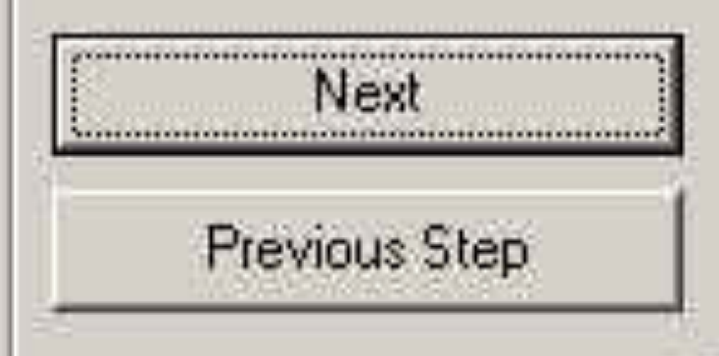 Each
step of the preview calibration procedure is finished by pressing the NEXT
button.
Each
step of the preview calibration procedure is finished by pressing the NEXT
button.
With the Previous Step button you can go backward step
by step. At some steps this option is not available.
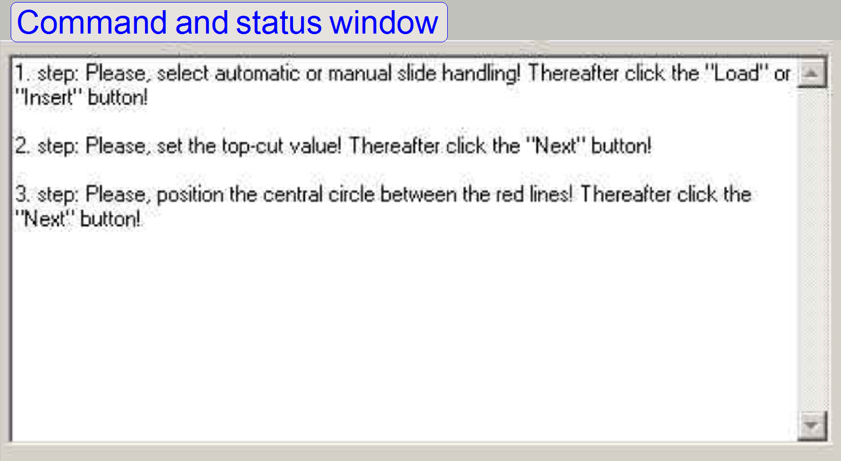 The command
and status window tells you the instructions, what to do and results of
calculations.
The command
and status window tells you the instructions, what to do and results of
calculations.
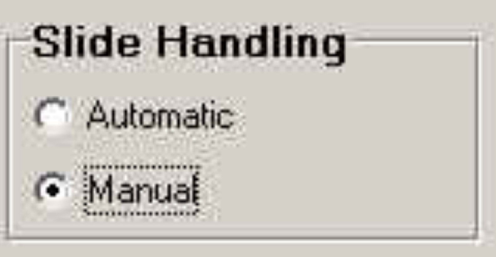 Step 1: Automatic
slide handling: uses
the slide insert and remove options offered by the SlideScanner.exe
program.
Step 1: Automatic
slide handling: uses
the slide insert and remove options offered by the SlideScanner.exe
program.
Manual: moves
the specimen holder to a position where a slide can be easily inserted or
removed. The insert or remove procedure is done by the user, manually (e.g. if
the magazine unit is removed).
![]() “Insert or
remove a slide manually”
“Insert or
remove a slide manually”
Step 2: Cut from top:
![]() Go to
the position Y= 14000 with the Y-Stage tool, so that the top of the slide is
visible. If the preview camera is already adjusted and there is a shadow
visible on the top part, it has to be cut off with this option. Because the
entire preview is assembled from three preview camera images, this shadow have
to be fully cut. See also „Adjust the
preview camera position”.
Go to
the position Y= 14000 with the Y-Stage tool, so that the top of the slide is
visible. If the preview camera is already adjusted and there is a shadow
visible on the top part, it has to be cut off with this option. Because the
entire preview is assembled from three preview camera images, this shadow have
to be fully cut. See also „Adjust the
preview camera position”.
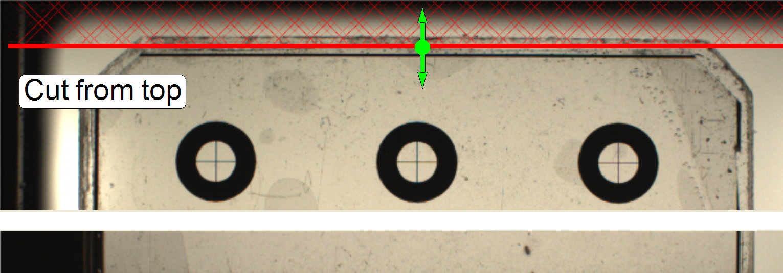
Step
3: Position the central circles between the red lines:
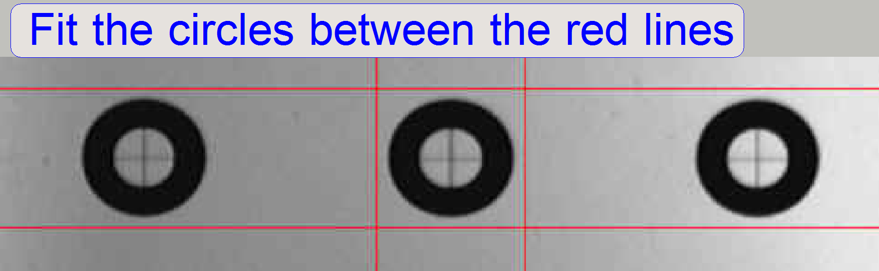 With
the tools in the “X- Y-Stage area” the desired result will be reached. An
accuracy of 200 steps is enough.
With
the tools in the “X- Y-Stage area” the desired result will be reached. An
accuracy of 200 steps is enough.
Step
4: Adjust the threshold until only the
circles are visible:
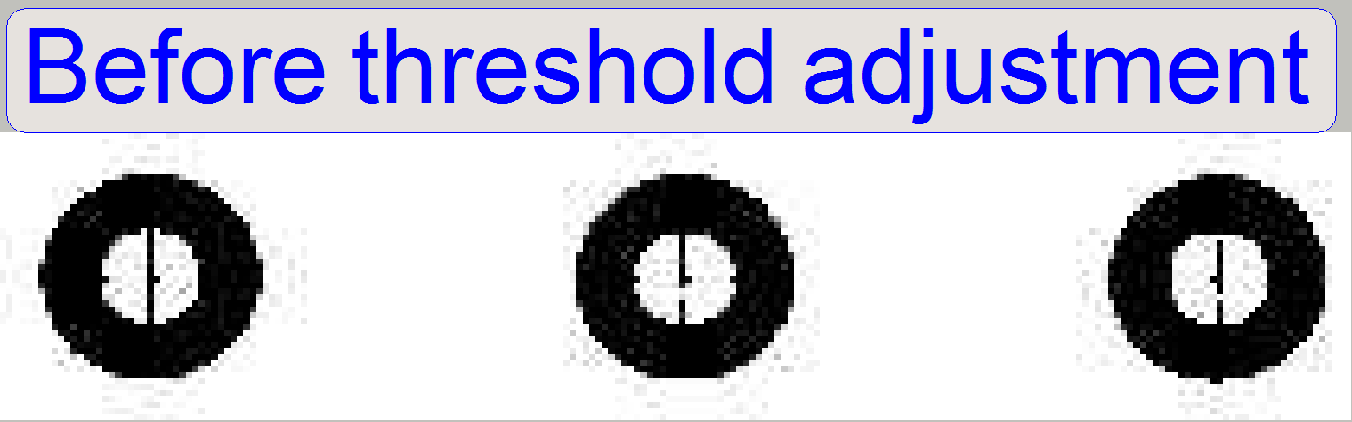
Remark: This step is done only one time, if the three circles
are in the middle of the preview window.
Before
threshold adjustment
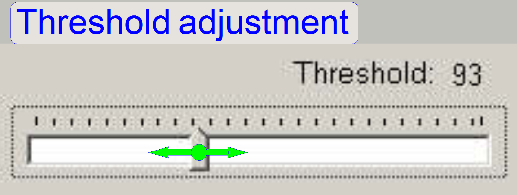 Adjust
threshold until the inside of the circles is empty, without dots or lines, but
the circles are fully visible.
Adjust
threshold until the inside of the circles is empty, without dots or lines, but
the circles are fully visible.
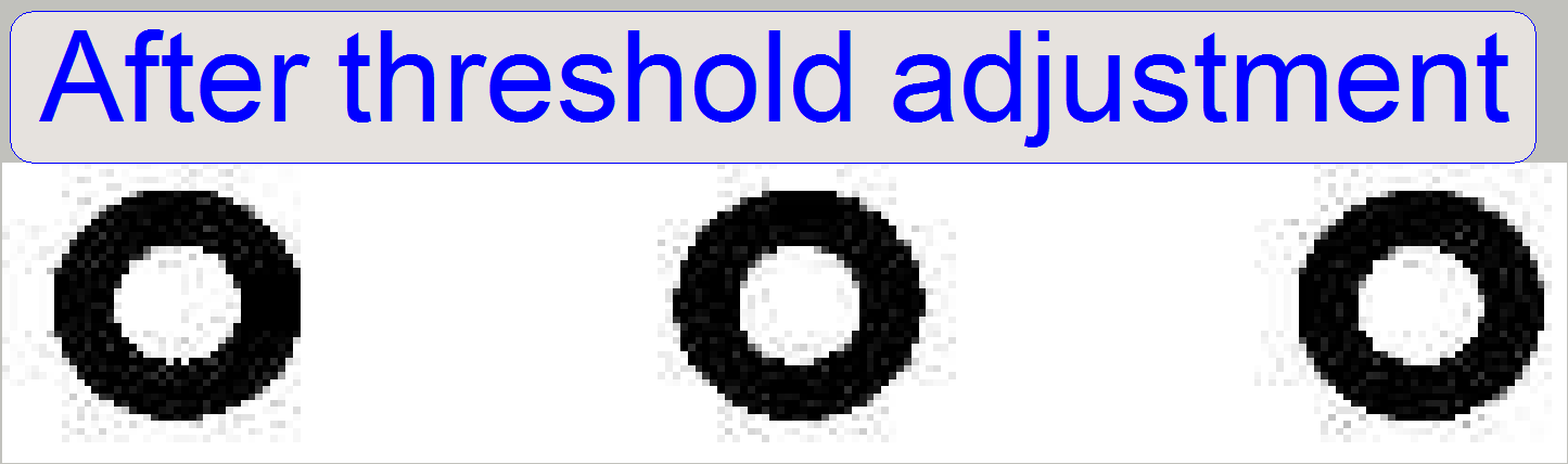 The desired
result after the threshold adjustment
The desired
result after the threshold adjustment
Step
5: Place the red squares over the circles:
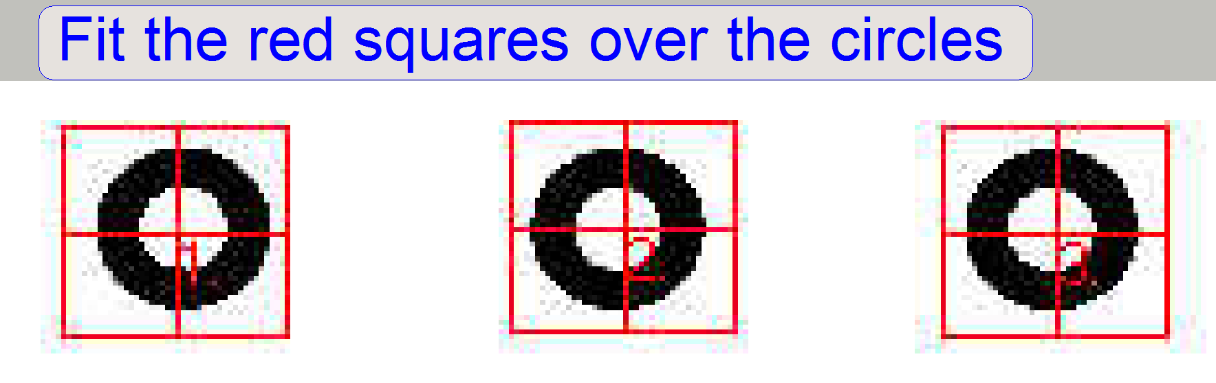 The
cross in the middle of the red squares should be inside of the circle, but an exact
match with the center of the circle is not required. The squares are numbered;
please place the squares in the right order: 1, 2, and 3 from left to right.
The
cross in the middle of the red squares should be inside of the circle, but an exact
match with the center of the circle is not required. The squares are numbered;
please place the squares in the right order: 1, 2, and 3 from left to right.
- By dragging one of the red squares with the left mouse button all
three squares are moved at the same time, by dragging with the right
button, you can move each square separately.
· The
squares are numbered; please place the squares in the right order: 1, 2, 3 from
left to right.
Step
6: If the calculated circle centers are
correct...
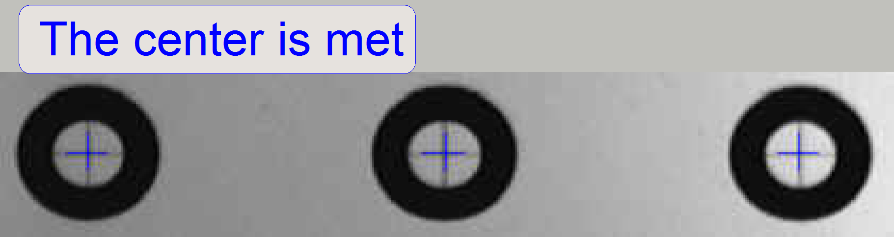 The
correct result is shown on the right.
The
correct result is shown on the right.
The blue crosses meeting the center
of the circles.
Step 7, 8 and 9:
Repeat the steps 3, 5 and 6 on the
top of the camera window logically.
Step 10, 11 and 12:
Repeat the steps 3, 5 and 6 on the bottom
of the camera window logically.
Step 13: Move the stage to the most
homogenous background illumination
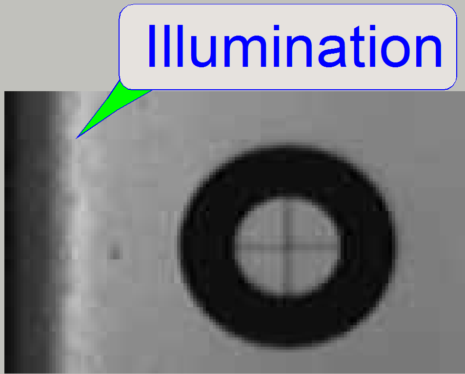 Some times on the
left edge of the camera window illumination differences are visible. By moving
the stage to the right by several hundreds of steps the uneven illumination can
be eliminated or minimized.
Some times on the
left edge of the camera window illumination differences are visible. By moving
the stage to the right by several hundreds of steps the uneven illumination can
be eliminated or minimized.
·
If the stage is moved too much in the direction X-min
of the scan area, the unevenly part of the illumination may be visible.
Without
uneven illumination
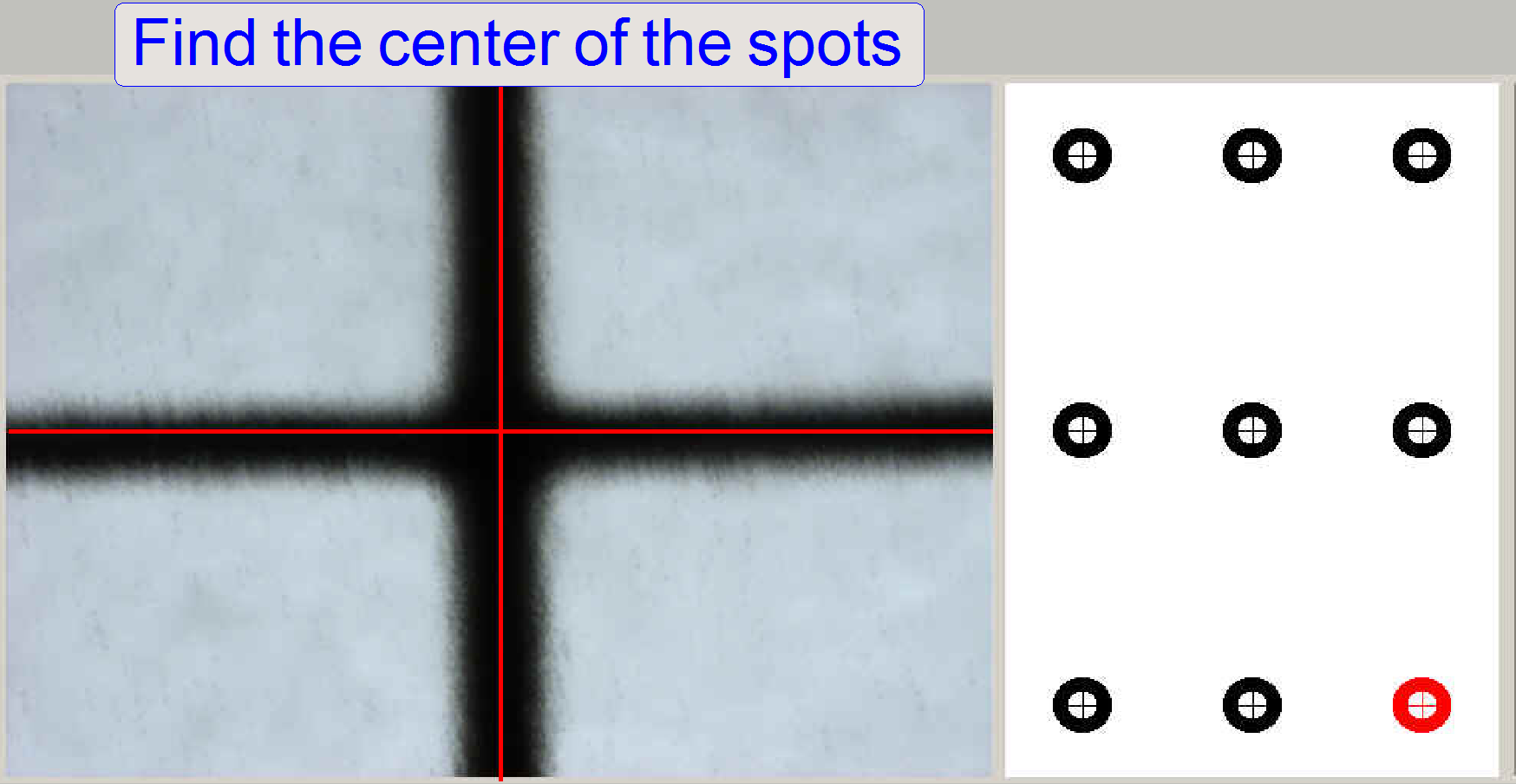
Step 14: Find
the centre of the spots
Fit the center of the black cross with the
centre of the red cross by using the X- Y- stage control buttons.
 Before you press
the NEXT button for the first time, you can correct the scan camera position /
rotation angle and the 20x objective focus position.
Before you press
the NEXT button for the first time, you can correct the scan camera position /
rotation angle and the 20x objective focus position.
After starting this step the auto focus option
adjusts the focus position for the scan camera. Now you can adjust the focus
position of the objective for the scan camera manually, if required.
After pressing the button “TEST Backlash” check
the position of the crosses to each other again and correct this if necessary.
After pressing the TEST button the X-Y-stage is moved to the next circle by
pressing the NEXT button (the same button with double task).
 Repeat this procedure with all 9 circles
· Since the software
version 1.15 only the 4 corner circles are used.
Step 15: Place the red
squares onto the corner circles
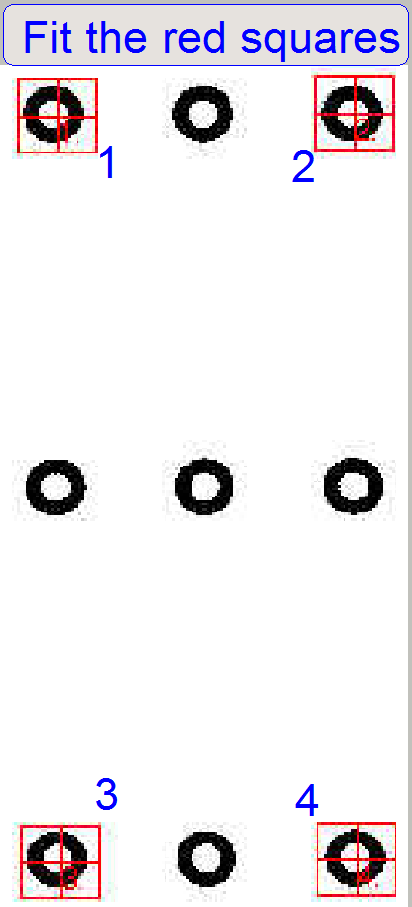 The
cross in the middle of the red squares should be inside of the circle, but an
exact match with the center of the circle is not required.
The
cross in the middle of the red squares should be inside of the circle, but an
exact match with the center of the circle is not required.
By dragging one of the red squares
with the left mouse button all four squares are moved at the same time, by
dragging with the right button you can move each square separately.
· The
squares are numbered! Please place the squares in the right order: 1, 2, 3 and
4 from top left to bottom right.
Step 16:
Fit the barcode area into
the red square
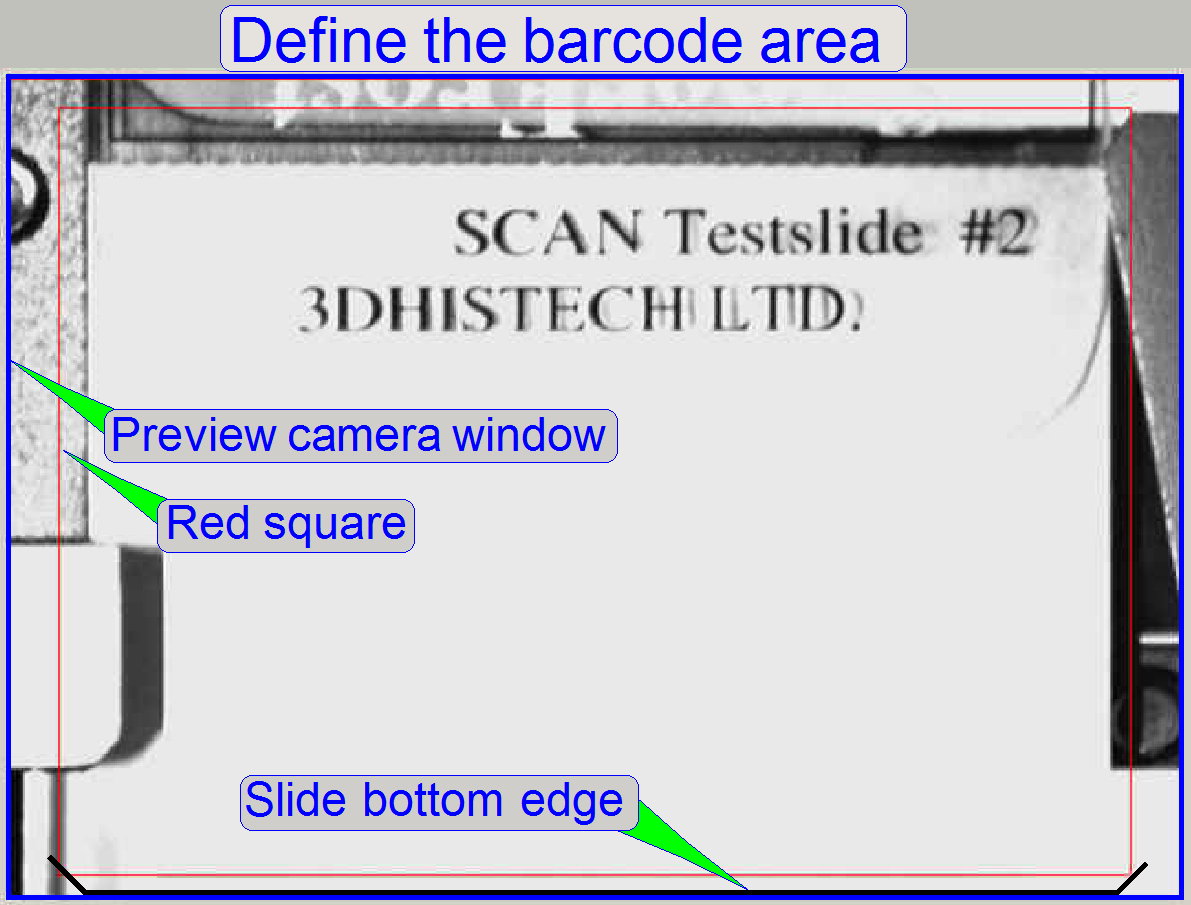
With the X-Y-stage control buttons bring the
barcode area of the slide into the red rectangle. The border, given by the red
rectangle should be a little bit away from the left slide edge. Because the
slide width tolerances of the allowed slide size are growing up or reduces the
right side of the slide, the right edge should be fully inside the red
rectangle if we are not using the widest possibke slide.
The lower edge of the slide should be equal with
the lower edge of the preview camera window.
Furthermore, we adjust now the barcode
illumination.
· Bend the LEDs
carefully so, that the barcode area is illuminated nearly homogenously.
· Modify the
exposure time of the preview camera to lower values, so the adjustment can be
checked easier.
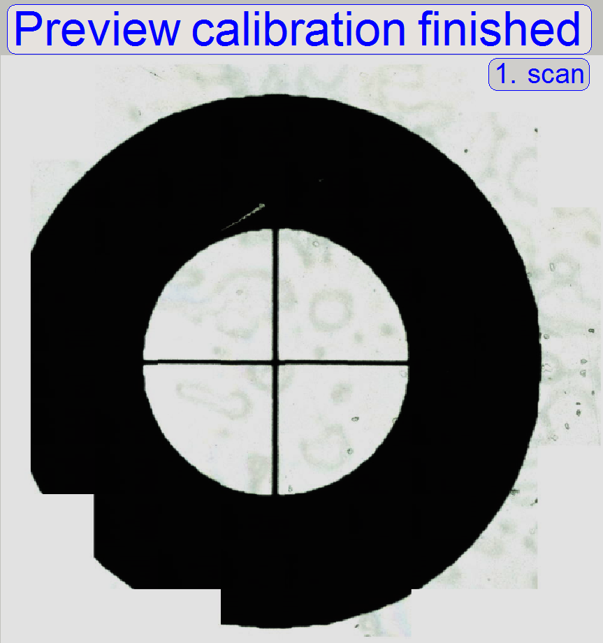
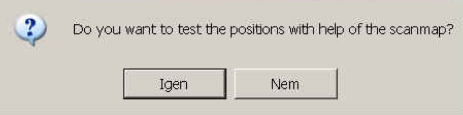 After
finishing step 16 a dialog appears on the screen and you can check
the result of preview calibration visually, if you answering YES (Igen).
After
finishing step 16 a dialog appears on the screen and you can check
the result of preview calibration visually, if you answering YES (Igen).
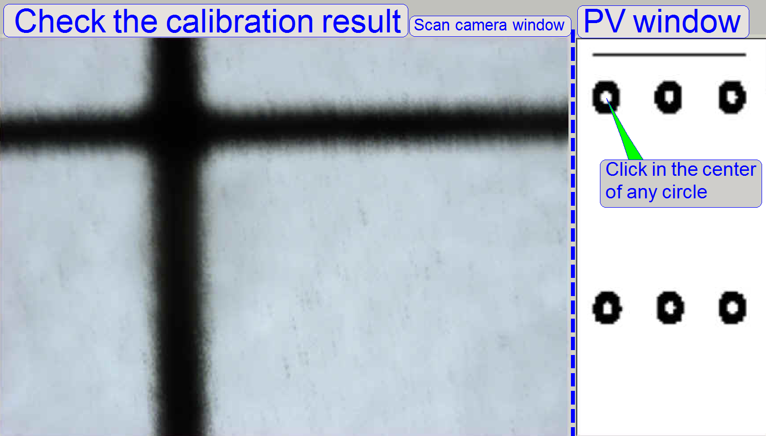
 Step 17: Test the result
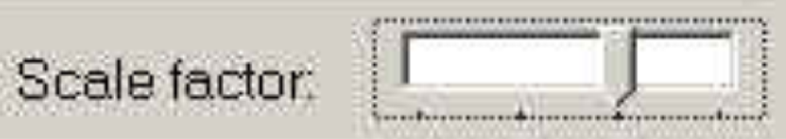
By selecting a higher resolution with
the “Scale factor” the possibility to find the centre of the circle is higher.
The goal of this option is that by clicking with the cursor in the middle of a
circle on the preview window (right window), to see the center of the circle in
the camera window.
This way, you can check the result
of the calibration before exiting the calibration program.
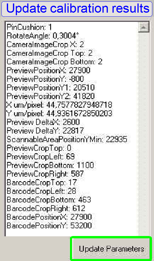 At the end of calibration, please do not forget to
save the resulting parameter values to the file “MicroscopeConfiguration.ini” by
pressing the ”Update Parameters” button.
At the end of calibration, please do not forget to
save the resulting parameter values to the file “MicroscopeConfiguration.ini” by
pressing the ”Update Parameters” button.
Exit the preview
calibration program by pressing the button DONE.
Next we scan the top left circle with the program
“SlideScanner.exe”.
Adjust
the pixel position of the preview camera
 Adjust
the pixel position of the preview camera to the field of view of the scan
camera.
Adjust
the pixel position of the preview camera to the field of view of the scan
camera.
The goal of this
adjustment is, to see the same part of the tissue with the scan camera and the
preview camera also.
This task is done
by the preview calibration program, but the software is not able to find this
position correctly. Therefore, we must adjust the position of the pixel of the
preview camera more precise to the position of the field of view to the scan camera
“manually” by modifying pre-calculated parameter values.
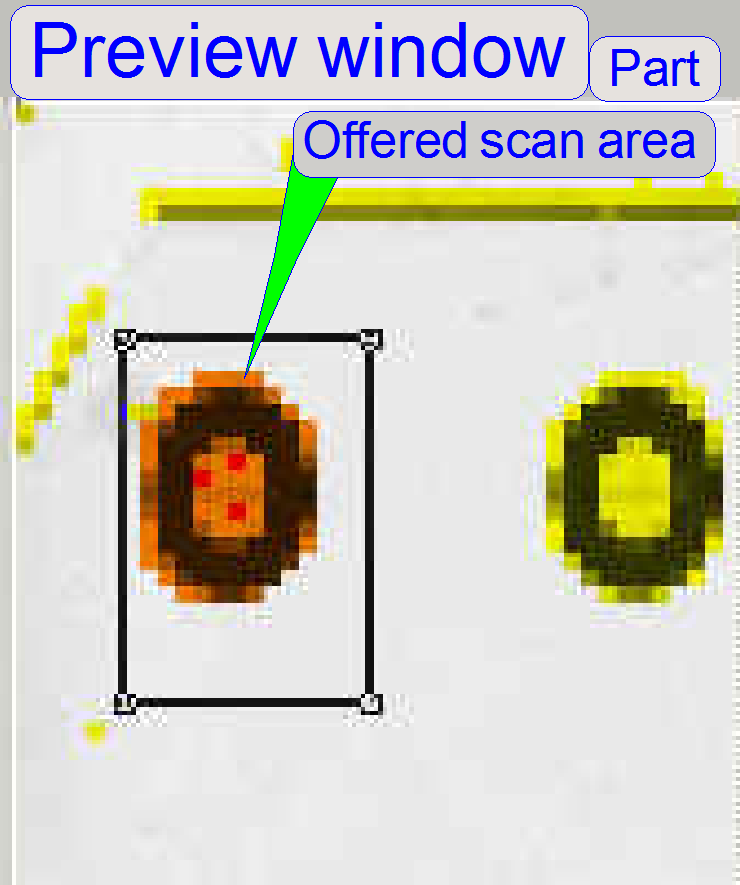
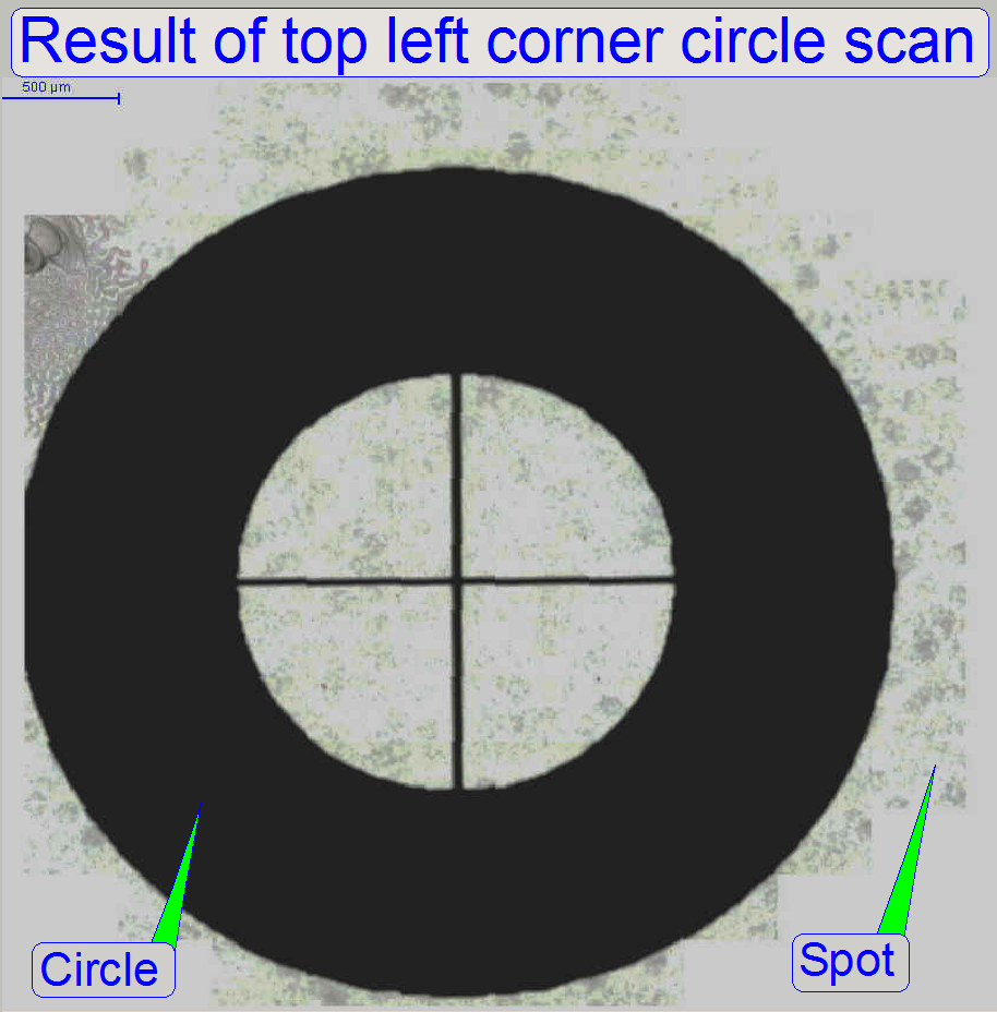
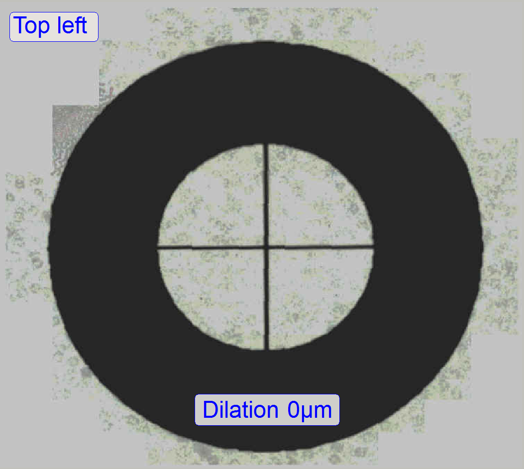
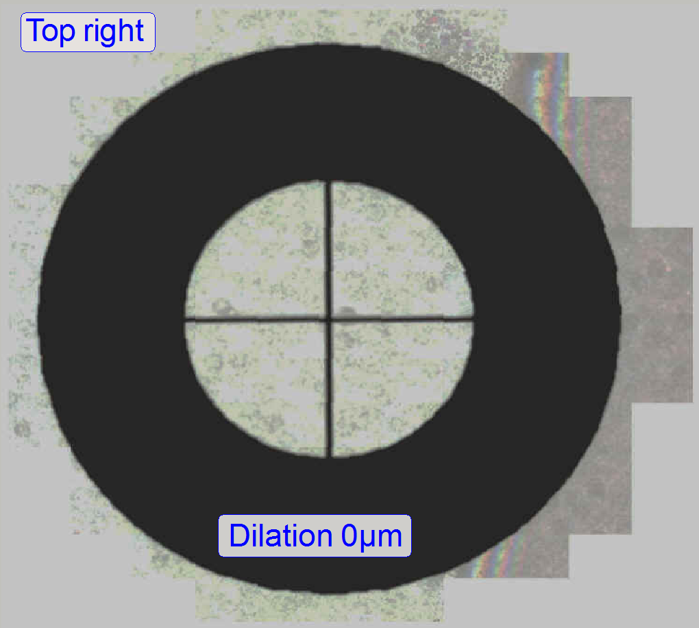
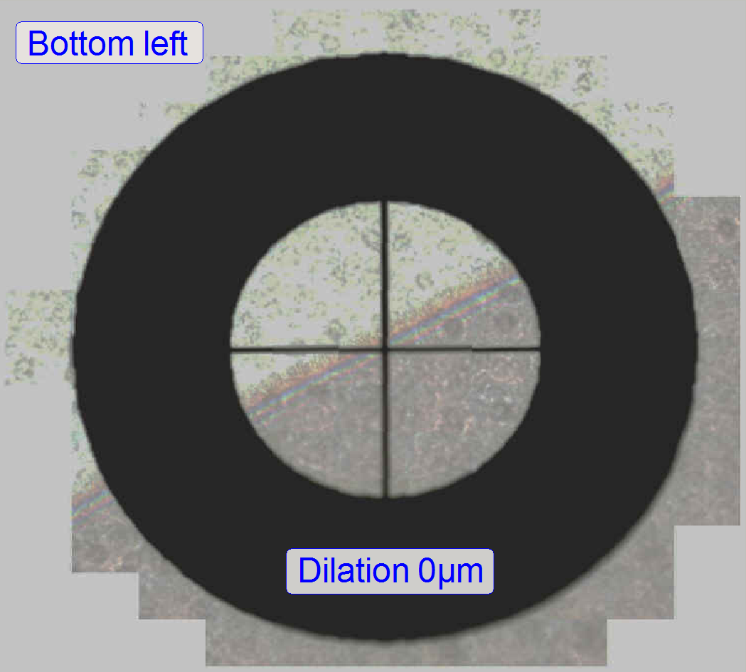
As shown on the
right the scan program offers in the preview window the entire circle for
scanning (dilation=0; the red-brown area).
By checking the
scan result with the viewer, we can see, the circle is cut, so the offered area
is incorrect.
·
The size of the cut part is variable.
This chapter
describes which parameter values must be modified to fit both areas.
Important remark
·
The offered scan area, offered by the
preview camera’s view, will be named as “Spot”
·
The really scanned area is represented by
the “Circle”.
·
Of course, the entire area is scanned by
the scan camera, but our reference position will be the center of the circle in
relation to its surrounding.
·
In the picture above, the circle is cut,
this means, the offered area for scanning (offered by the preview camera) will
not met the real position of the circle on the slide.
·
Therefore, we have to shift the offered
preview area (the spot) to the left and a bit downward; so we will see the
circle in the center of the offered scan area.
·
All modifications, described below are
done with the offered scan area, offered by the preview camera’s view!
![]() Pixel position
and corrections
and FOV
and Preview
Pixel position
and corrections
and FOV
and Preview
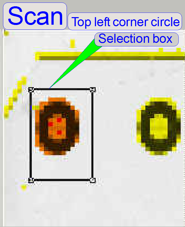
Scan the top
left corner circle
 Start
the SlideScanner.exe, load a magazine
with the calibration slide, insert the calibration slide and set the following
options:
Start
the SlideScanner.exe, load a magazine
with the calibration slide, insert the calibration slide and set the following
options:
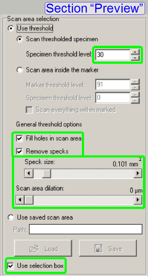
In the preview
section check the box “Use selection box”.
Select the upper left corner circle of the calibration
slide with the selection box as shown. Hereby it is important, that a small not
scanned area is included inside the selection box (white area).
Select the
options “Fill holes in scan area” and “Remove specks”.
Select the “Scan
area dilation” to zero.
With “Manual threshold” checked, adjust the threshold
of the preview so, that unwanted pixels are not disturbing the view.
Adjust the “Speck
size” as needed.
Select
“Live view” in the section “Focus”.
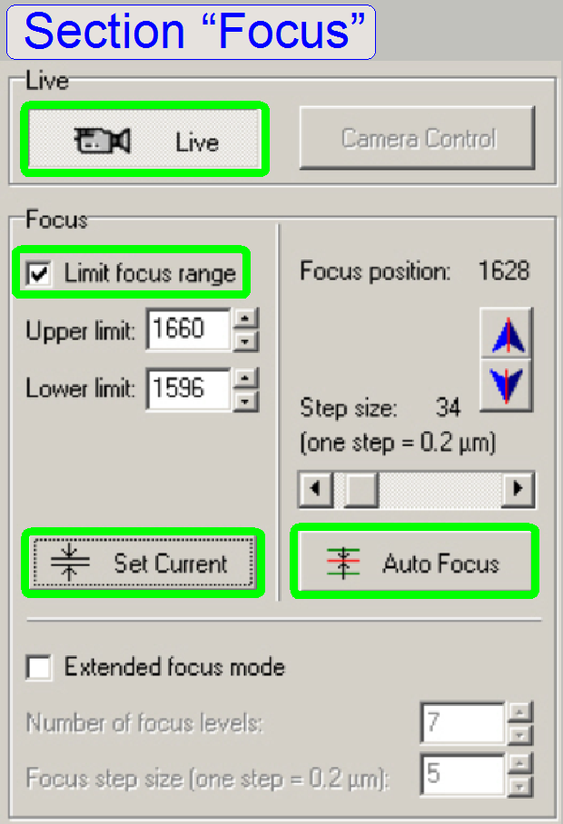
Find any edge or a part of the cross with the
positioning tool (below the preview window) in the upper left corner circle in the
preview window and bring it into focus.
Check the option “Limited focus range” and click “Set
current”.
This way we are using the limited focus range for the
upper left corner circle during the scan process.
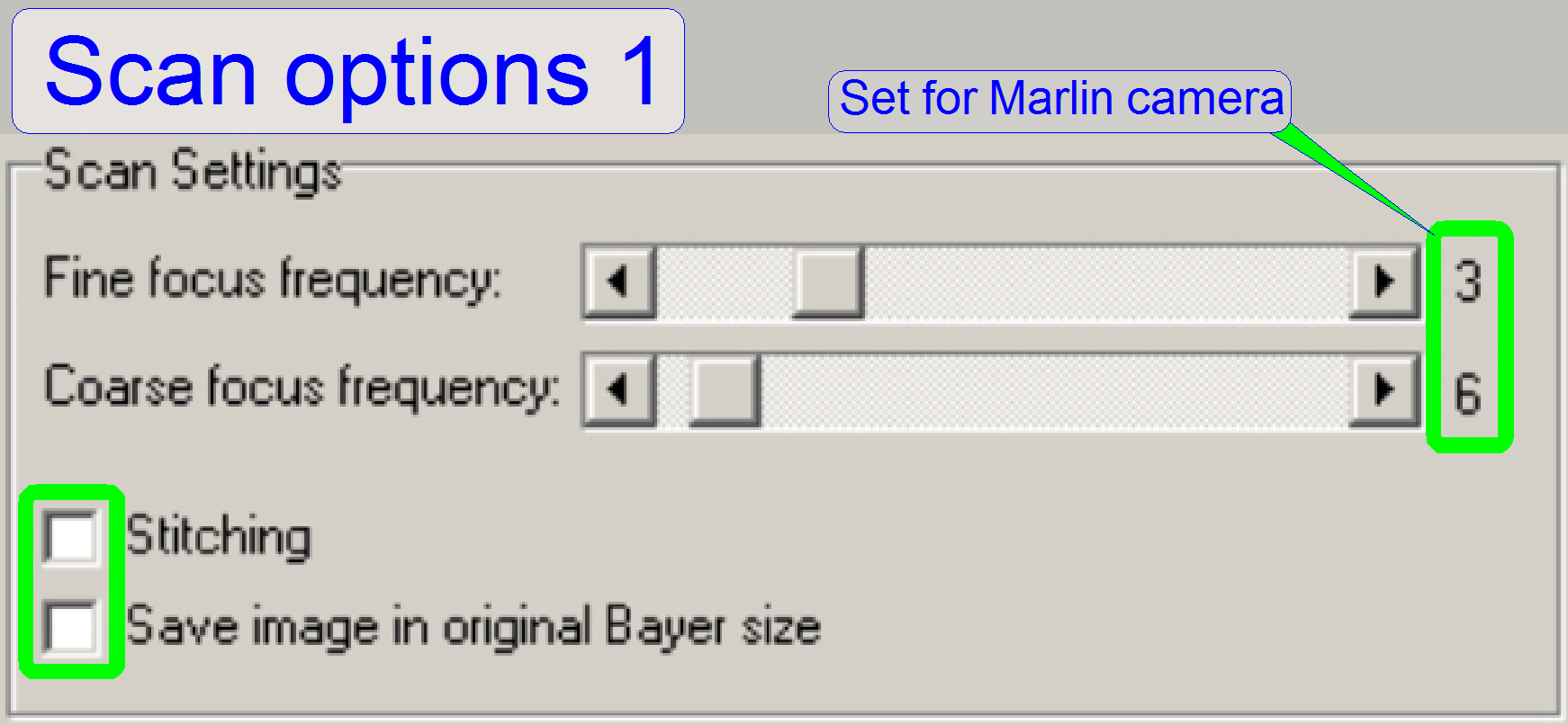
In the dialog “Scan options” uncheck the checkbox
“stitching”.
The focus frequency values are shown for the marlin
camera.
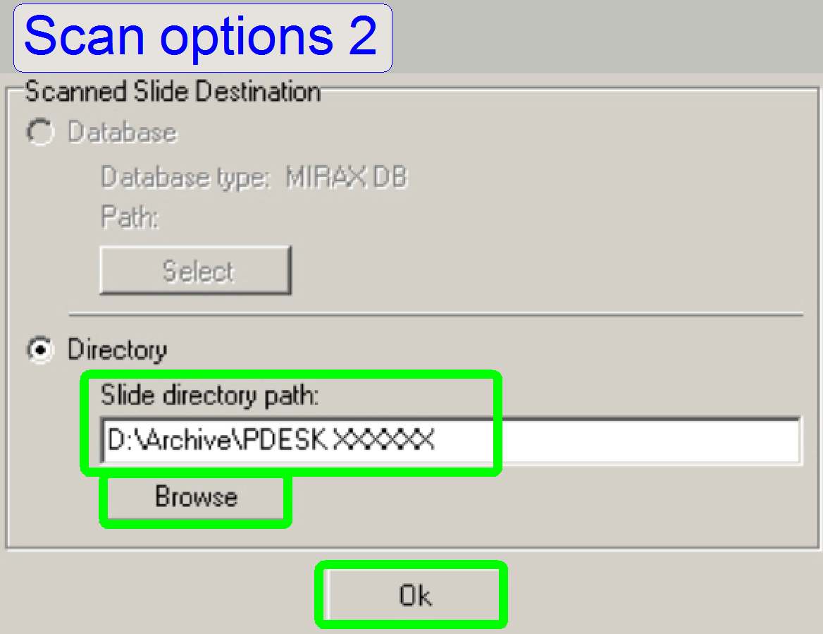 Define
a destination path for the slide to be scanned.
Define
a destination path for the slide to be scanned.
If the directory already exists, you can select it by
using “Browse”, otherwise you can type in a path in the field “Slide directory
path”.
Exit the dialogue “Scan options” with OK.
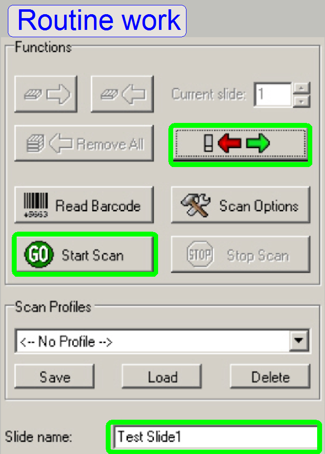 Type
in a file name and start the scan process.
Type
in a file name and start the scan process.
 With
the viewer program we checking now the result, it can be somewhat like this.
With
the viewer program we checking now the result, it can be somewhat like this.
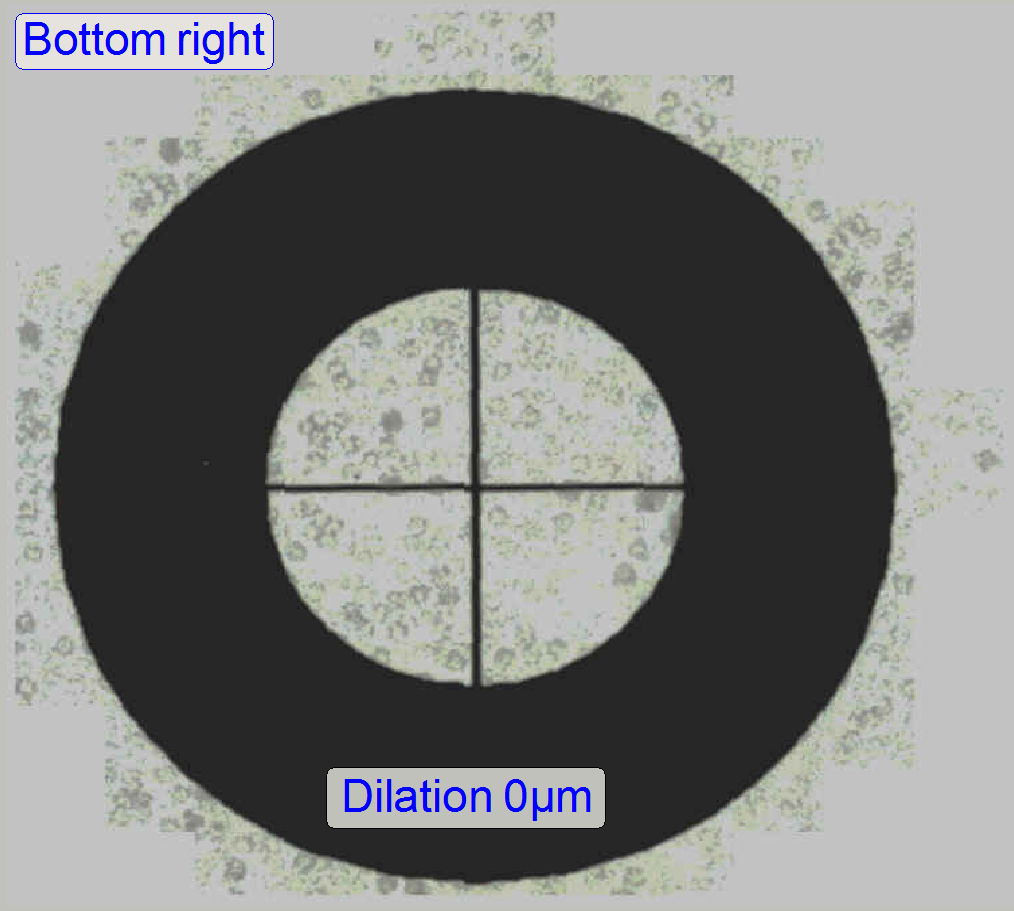
As visible, the circle is situated in the bottom left
corner of the spot, defined by the preview camera. Therefore, the circle should
be moved to the right and upward in relation to the spot.
· In practice,
we are shifting the spot (the tissue area, offered by the preview camera)
downward and to the left, so, the circle position moves center-ward!
· The spot
represents the scan area, offered by the preview camera.
· The
circle represents the actual position of the scan camera in relation to the
preview camera (the spot).
· The
goal is now to move the circle into the center of the spot.
Use this calculation
table to correct the position of the circle
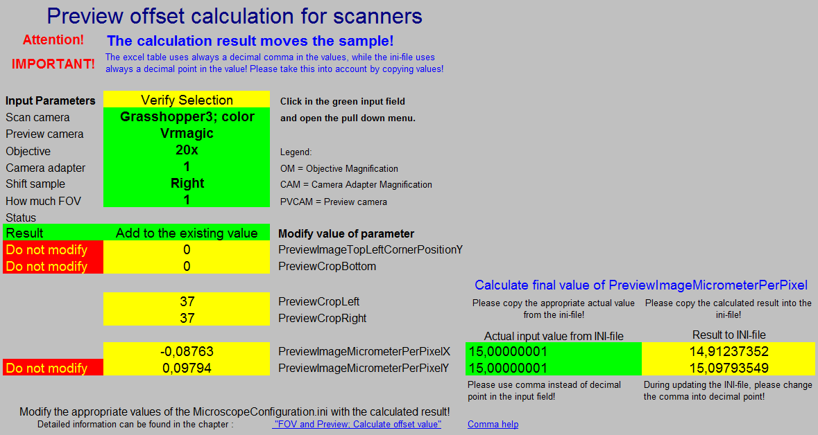
This
table is available as an Excel file and by setting the desired input parameters
(In the green pull down menus) the configuration in front of you can be
selected. The result is shown in the yellow fields; this value should be added
or subtracted respectively from the named parameter value. The parameters are
found in the file MicroscopeConfiguration.ini section
[PreviewAndBarcodeScanning].
The “Status” line shows mistakes, if the selected
parameters can not be used in conjunction with the defined scan camera, but the
calculated result is always correct for actually set options!
· The status informs you, that the selected combination is incorrect, it
is a warning only!
![]() “FOV and
Preview”; “Calculate
offset value” and “Sensor characteristics”
“FOV and
Preview”; “Calculate
offset value” and “Sensor characteristics”
Preview
corrections and pixel position
 Scan
the 4 corner circles of “Test slide #2”. To achieve a good scan quality it is
necessary to define a focus limit range in the option “Focus” of the scan
program. With the Pannoramic viewer program we are checking the
relation between tissue (the circle with cross) and the spot (visible
surrounding of the sample) of the scanned test slide #2. The goal is to fit the
image, offered by the preview camera (the spots) with the circles, the real
position of the tissue. Use the table above to calculate the values for fitting
the tissue nearly to the center of the spot.
Scan
the 4 corner circles of “Test slide #2”. To achieve a good scan quality it is
necessary to define a focus limit range in the option “Focus” of the scan
program. With the Pannoramic viewer program we are checking the
relation between tissue (the circle with cross) and the spot (visible
surrounding of the sample) of the scanned test slide #2. The goal is to fit the
image, offered by the preview camera (the spots) with the circles, the real
position of the tissue. Use the table above to calculate the values for fitting
the tissue nearly to the center of the spot.
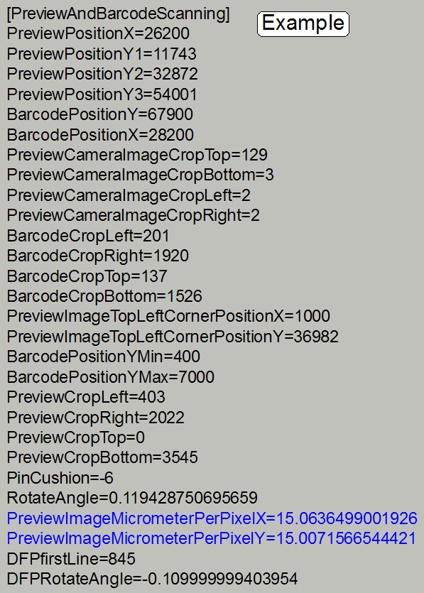
The appropriate parameters are found in the file
“MicroscopeConfiguration.ini” section [PreviewAndBarcodeScanning]. In
reality, we are moving the spot (the area, seen from the preview camera), not
the tissue (position of the scan camera). All corrections described here are
made with the preview image. The calculated values are added to or subtracted
from the actual values. For correction you can use integer values only (except “PreviewImageMicrometerPerPixelX”
and
“PreviewImageMicrometerPerPixelY”), fractions should be rounded.
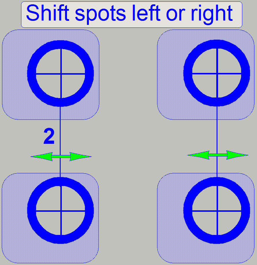
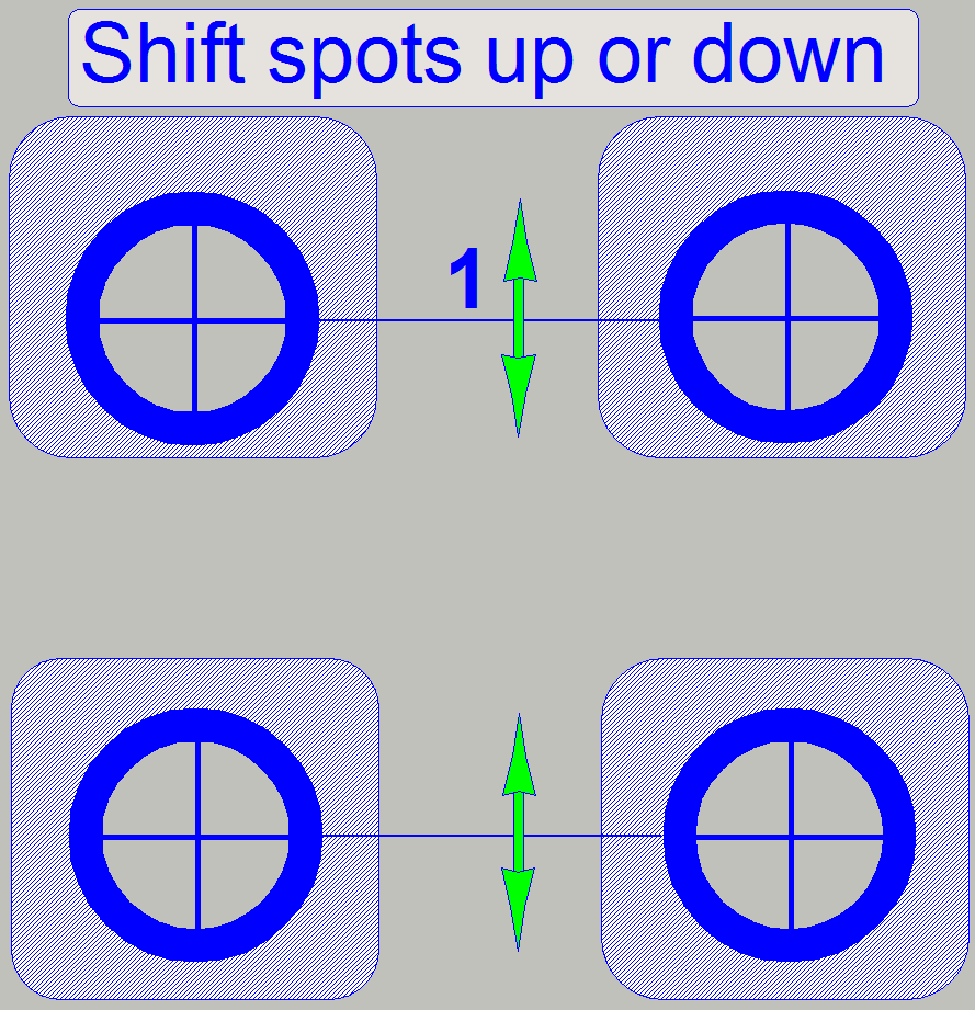 With
this correction the entire tissue (all four corner circles) are moved seemingly
up or down respectively and only the circles connected with line
“1” should be observed after correction and scanning, in relation to the
spots of the previous scan result. In reality the position of the scan area,
seen by the preview camera is modified (the position of the spot). This way,
the pixels, seen by the preview camera are adjusted to the FOV of the scan
camera. In some cases, you are unable to fit the circles exactly; then you
should use an optimum value. The parameter value to be modified for this
adjustment is “PreviewImageTopLeftCornerPositionY” and is
situated in the file “MicroscopeConfiguration.ini” section
[PreviewAndBarcodeScanning].
With
this correction the entire tissue (all four corner circles) are moved seemingly
up or down respectively and only the circles connected with line
“1” should be observed after correction and scanning, in relation to the
spots of the previous scan result. In reality the position of the scan area,
seen by the preview camera is modified (the position of the spot). This way,
the pixels, seen by the preview camera are adjusted to the FOV of the scan
camera. In some cases, you are unable to fit the circles exactly; then you
should use an optimum value. The parameter value to be modified for this
adjustment is “PreviewImageTopLeftCornerPositionY” and is
situated in the file “MicroscopeConfiguration.ini” section
[PreviewAndBarcodeScanning].
To shift the spots downward, increase the value of the
parameter “PreviewImageTopLeftCornerPositionY”.
· In the
example on the right, increase the value of the parameter “PreviewImageTopLeftCornerPositionY”.
![]() Pixel position and corrections
and FOV
and Preview
Pixel position and corrections
and FOV
and Preview
 With
this correction the entire tissue (all four corner circles) are seemingly moved
left or right respectively and only the circles, connected with line “
With
this correction the entire tissue (all four corner circles) are seemingly moved
left or right respectively and only the circles, connected with line “
To shift the spots to the right, increase the value of
the parameter “PreviewCropLeft”.
· In the
example on the right, increase the value of the parameter “PreviewCropLeft”.
![]() Pixel position and corrections
and FOV
and Preview
Pixel position and corrections
and FOV
and Preview
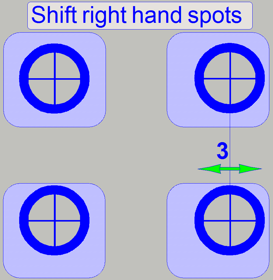 The
pixel size of the preview will be corrected or modified in X-direction of the
entire sample. Because the influence of this parameter to the left hand part of
the sample (circles) is very small, you can really use it to correct the
position of the right hand circles, connected with line “
The
pixel size of the preview will be corrected or modified in X-direction of the
entire sample. Because the influence of this parameter to the left hand part of
the sample (circles) is very small, you can really use it to correct the
position of the right hand circles, connected with line “
· In
the example on the right, increase the value of the parameter “PreviewImageMicrometerPerPixelX”.
![]() Pixel position and corrections
and FOV
and Preview
Pixel position and corrections
and FOV
and Preview
 The
pixel size of the preview will be corrected or modified in Y-direction of the
entire preview image. Because the influence of this parameter to the upper
circles is very small, you can really use it to correct the position of the
lower circles, connected with line “
The
pixel size of the preview will be corrected or modified in Y-direction of the
entire preview image. Because the influence of this parameter to the upper
circles is very small, you can really use it to correct the position of the
lower circles, connected with line “
· In the
example on the right, decrease the value of the parameter “PreviewImageMicrometerPerPixelY”.
![]() Pixel position and corrections
and FOV
and Preview
Pixel position and corrections
and FOV
and Preview
Prepare the
preview for scanning
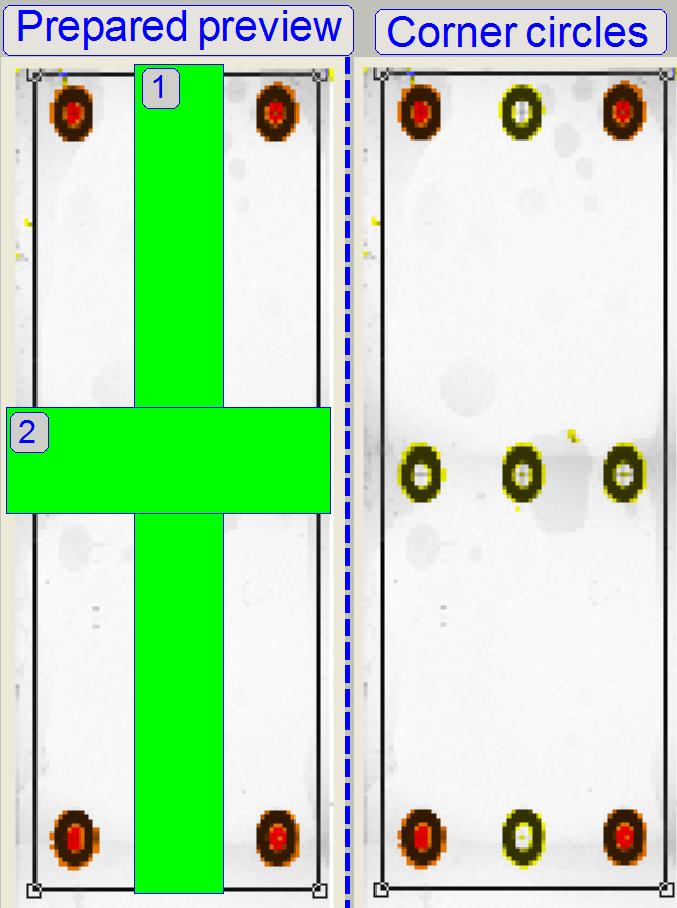 Start
the Pannoramic SCAN software, load a magazine with the calibration
slide, insert the calibration slide and prepare the preview of the test slide
#2 as described above in the chapter “To scan the upper left corner
circle”.
Start
the Pannoramic SCAN software, load a magazine with the calibration
slide, insert the calibration slide and prepare the preview of the test slide
#2 as described above in the chapter “To scan the upper left corner
circle”.
In the preview tools select the tools:
· “Square
or Rectangle” (a)
· “Not
scanned” (b) and
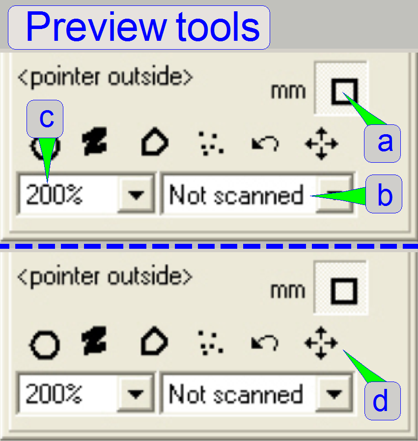 · “Zoom
200%” (c).
· “Zoom
200%” (c).
By drawing rectangles, exclude the horizontal and
vertical center circles from the scan process as shown with 1 and 2 of “The
prepared preview”.
With the limited focus the scan process of the test
slide is done quicker and the circles are scanned sharpen. To ensure, that all
four circles are scanned sharpen, the focus position must be checked for each
of the circles, and depending on the focus position of each circle the limited
focus range must be defined.
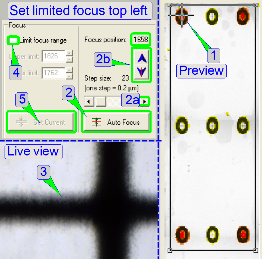
1. With
the positioning tool selected, find the center or any edge of the circle
(1).
2. Press
the button “Auto focus” (2).
3. Select
a step rate of 5 or 10 focus steps and check the found focus position of
sharpness (2a, 2b).
4. If the
sharp life view is found (3), check the checkbox “Limited focus range” (4) and
press the button “Set current” (5). The software defines the limited focus range
by the upper limit = actual focus position + 32 focus steps and the lower focus
limit = actual focus position -32 focus steps.
Check or set the focus
limit for the other 3 circles
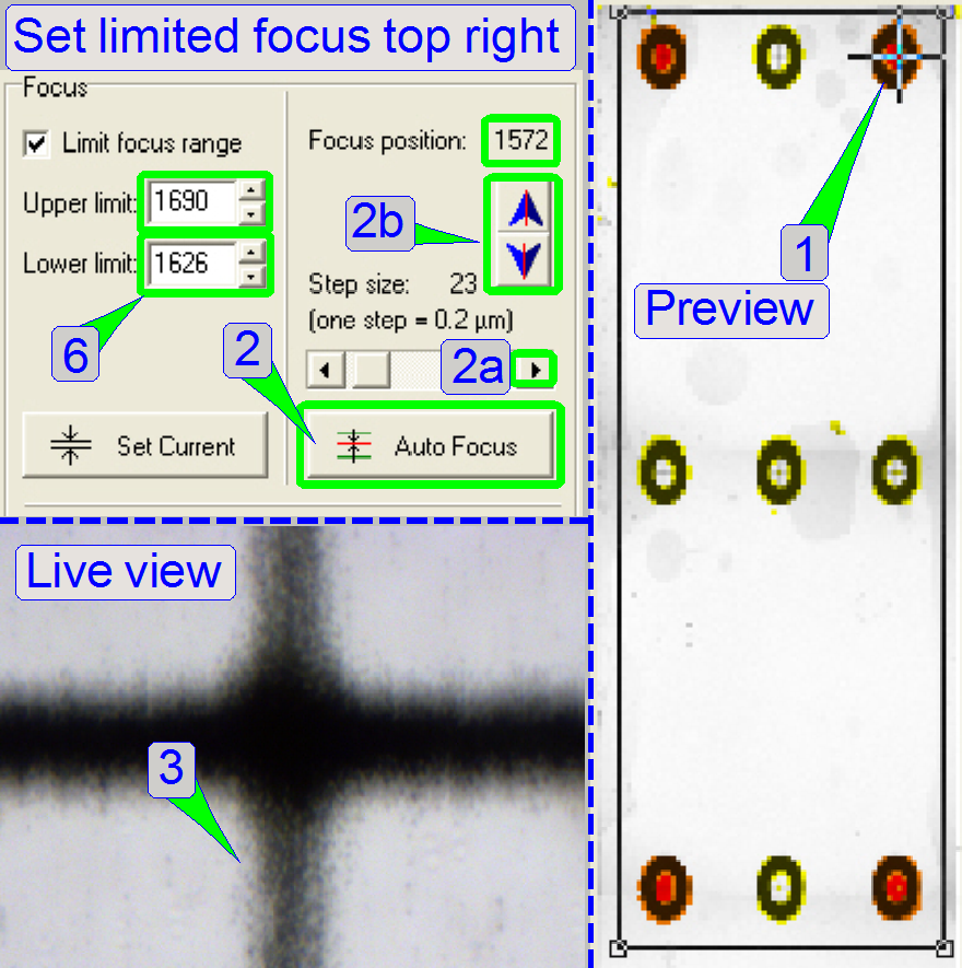
5. Repeat
steps 1 to 3 with the next circle.
6. Check
the found focus position in relation to the existing focus range. If the found
focus position is inside the existing focus limits, check the next circle.
7. If the
found focus position is outside the existing focus limit, type a new value for
the upper or lower focus limit respectively as required (6). In the example on
the right a value of 1560 for the lower limit would be acceptable. If the
scanned circles are partly not sharp, might be the focus range must be defined
larger.
Correct
the preview and adjust the pixel position
1. Insert
test slide #2 and prepare the preview so, that only the four corner circles
will be scanned. Check the focus position of all four corner circles as
described above and define a limited focus range. Use always a
different file name for each scanned slide.
2. Scan
test slide #2.
3. Switch
to SlideViewer.exe and load the just scanned test slide.
4. Check
the position of the upper two circles in relation to their spots. For better
visibility use the “color panel” “correction” option and shift the contrast
slider downward and the gamma slider fully up. So you get better contrast for
the spot and it will be more visible.
5. Calculate
the number of FOV for shifting the sample up or down respectively and modify
the appropriate parameters (PreviewImageTopLeftCornerPositionY and PreviewCropBottom) in
“MicroscopeConfiguration.ini” and save the file.
6. Exit
the entire SlideScanner.exe program and start it again to reload the
.ini files with the new parameter values. Repeat steps 1 to 6 until the
tissue fits their spots in Y-direction, see also above “Shift sample up / down.
If this adjustment is finished, go to step 7.
7. Repeat
Steps 1 to 6 logically, but now we adjust the spots by shifting them left
/right. See also above “Shift sample left / right. Repeat this
sequence until the position of the circles, connected with line “2” are in
the centre of their spots, so the X-position is defined. If this
adjustment is finished, go to step 8.
8. Repeat
Steps 1 to 6 logically, but now we are adjust the spots connected with line “3”by
shifting them left /right. This we achieve by modifying the parameter value
of Preview ImageMicrometerPerPixelX. See also above
“Shift the right hand spots”.
9. Repeat
Steps 1 to 6 logically, but now we are adjust the spots connected with line “4” by
shifting them up / down. This we achieve by modifying the parameter value
of PreviewImage MicrometerPerPixelY. See
also above “Shift the lower spots”.
· Please do not forget to uncheck the option “Limited focus range” and to
check the option “Stitching”.
 If the
preview calibration and the pixel size adjustment was done and the program
SlideScanner.exe is running, load a slide, increase the preview area size if
necessary and check the correctness of the scan area adjustment as
follows:
If the
preview calibration and the pixel size adjustment was done and the program
SlideScanner.exe is running, load a slide, increase the preview area size if
necessary and check the correctness of the scan area adjustment as
follows:
· After
the positioning tool is selected click on the edges and outside of the slide
(in the preview area window) and check after each click the correctness of the
position as described in the paragraph above “Check the found
limit position”. The limit of specimen holder movement is always
the scan area. If the focus pin is jamming or the check
sounds like metal, the scan area is too large and must be decreased at the
appropriate edge.
· Check
the corners also, especially the “rounded” corner.
Save
the file “MicroscopeConfiguration.ini” to the EEPROM of your scanner.
Barcode
reading and adjustments
For
technicians and sales managers!
 These
instructions describe the procedure to define the barcode area and the
adjustments necessary for reading barcodes with Pannoramic S_M_D scanners,
equipped with
These
instructions describe the procedure to define the barcode area and the
adjustments necessary for reading barcodes with Pannoramic S_M_D scanners,
equipped with
- The preview camera VRmc-8+ PRO or
DFK 21F04
and
- The preview objective, TAMRON
23FM16SP or the objective, used with the DFK camera
If the barcode reading is not allowed in the dongle for
the SlideScanner software, barcodes can not
be read; nevertheless the barcode dongle is connected.
Check the barcode reader unit for
necessary adjustments:
· If the barcode print quality on
the barcode area is high or acceptable and barcodes can be read, but some barcode
types are unreadable (with also a high print quality), then adjustments may be
needed.
Requirements
- Service program for Pannoramic scanners
(SlideScannerSrevice.exe) with actual license file
- Pannoramic SCAN and Pannoramic Viewer software
(SlideScanner.exe, SlideScannerViewer.exe) with actual license file /
dongle
- Dongle for barcode reading
- Installed Matrox library
for barcode reading (MIL 9.0; received with the installation CD)
- 1.5, 2.5, 3 and 5 mm hex key wrenches,
 Before
you start adjusting the components of the barcode reader, try to read barcodes of
different kind and codes and do the following checks; see also barcodes in practice:
Before
you start adjusting the components of the barcode reader, try to read barcodes of
different kind and codes and do the following checks; see also barcodes in practice:
1. If there is no
barcode readable or available:
· Check
the Matrox
driver installation
· Check
the presence of the dongle
for barcode reading
· Check
the validity of the license file or dongle
· Check
the focus
position of the preview camera
· Check
the size of the preview
objective aperture
· Check the
selected barcode type in the dialogue “Barcode settings”
2. If several barcodes are
unreadable:
· Check the barcode print quality on
the slide’s barcode area
· Check
the uniformity of
illumination on the barcode area
· Check the size of the barcode area
· Check the
focus position of
the preview camera
· Check
the size of the preview
objective aperture
· Check
the selected barcode type in the dialogue “Barcode settings”
Define the barcode area
We assume that the preview calibration procedure is
already done and the barcode area is defined properly. For details to define the
barcode area please refer to the “Step 16:
Fit the barcode area into the red square”.
Driver
installation
Attention:
· Do not copy the MIL Runtime folder to your desktop!
Instead copy the folder to C:\. Because there are a lot of long file- and
folder names inside the MIL Runtime folder, the maximal path length will exceed
the limit, and the install procedure can not be executed successfully. Never
install the MIL Runtime via network!
· For further information please refer to “Setup
the Matrox Imaging Library”.
Start the Pannoramic scan software and check the barcode readability.
Adjust the preview camera parameters and barcode
illumination for barcode
reading and preview capturing
For a successful barcode reading the adjustment
of the barcode
illumination, the correct setting of the focus position of the
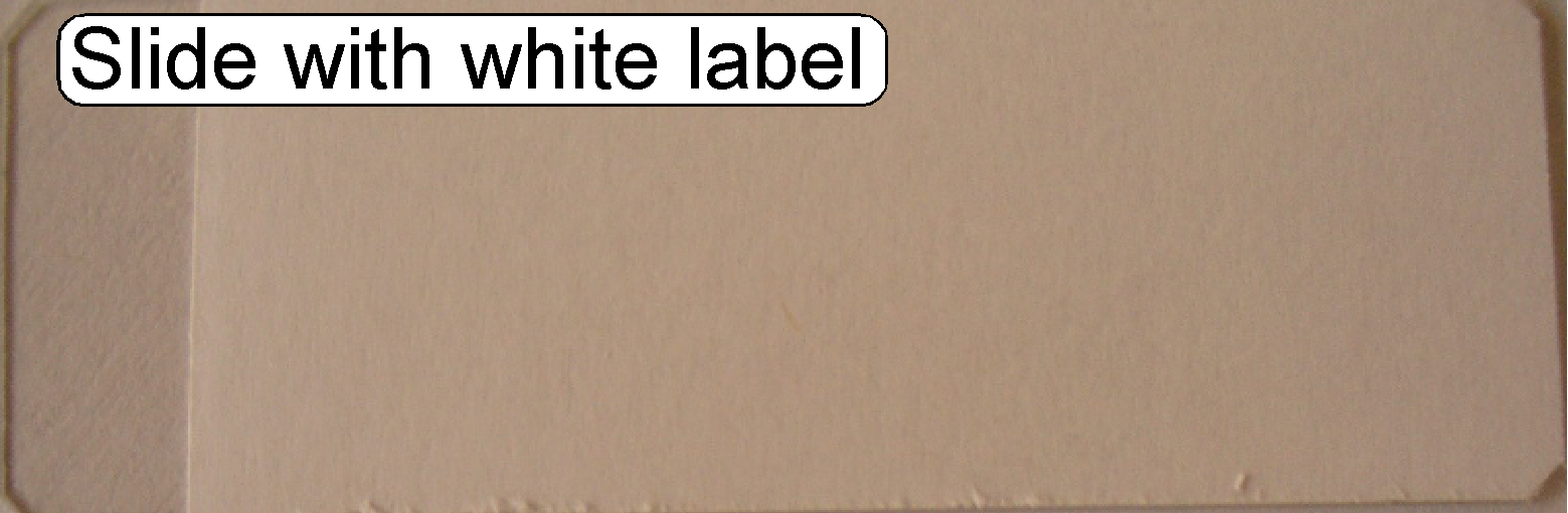
preview camera is essential. For this adjustment a slide with a white label
area and a barcode test set is required.
 Attention
If you adjusted the focus position of the preview camera objective you
have to do the preview calibration process again. For details to execute
the preview calibration please refer to the “Preview calibration above”.
A fully white barcode area can be created easily by
sticking a blank adhesive label onto the slide and the edges are cut around
with a utility knife. The white barcode area is required to check the
uniformity of illumination.
Adjust the barcode
illumination
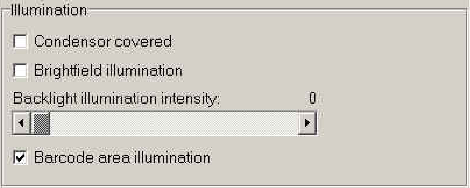
Start the program “SlideScanner.exe” with the service
password. Insert a slide with white label area and select the tab “Service” and
“Microscope control”. In the pull down menu “Video source” select the “Preview
camera”. After click on “live view” check the checkbox “Barcode area
illumination” and set the “Backlight illumination intensity” to zero.
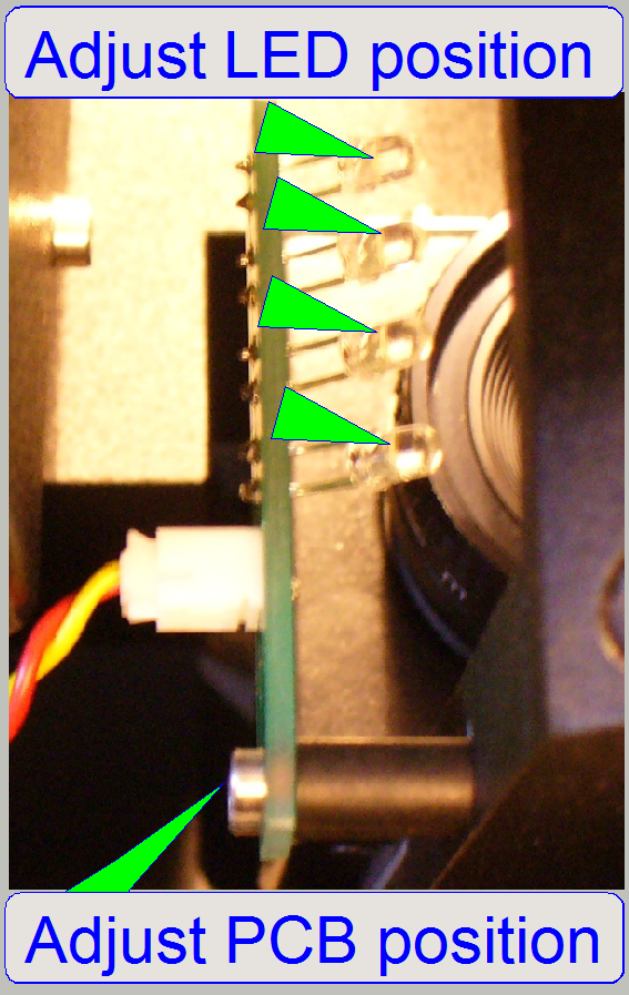
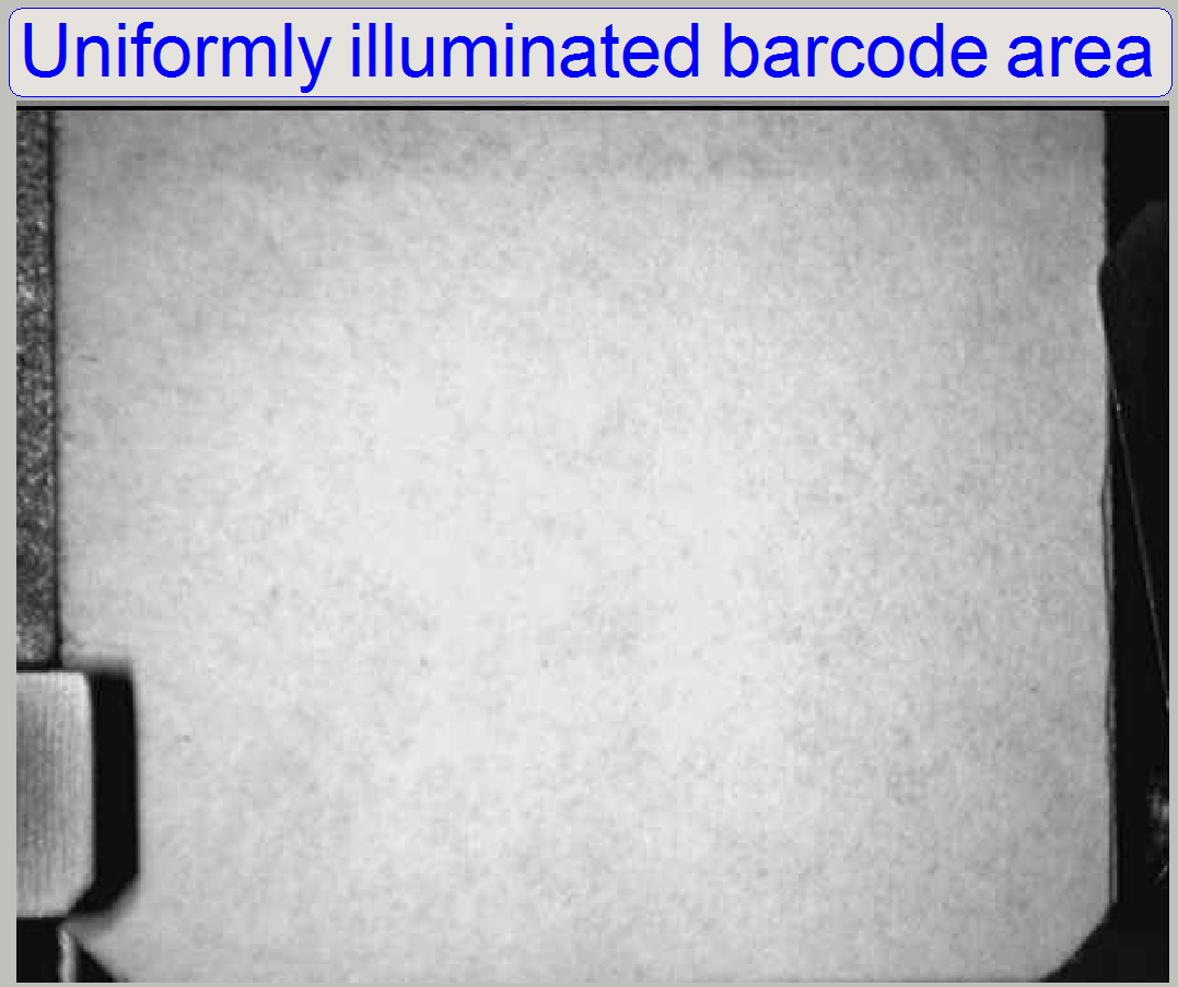
To reach a uniform barcode area illumination, please
bend the LED’s carefully and observe the live view. By modifying the PCB
position, the uniform illumination of the barcode area can be also reached.
1.
Adjust the position of the PCB.
2.
Bend the LEDs carefully until a uniform
barcode area illumination is reached.
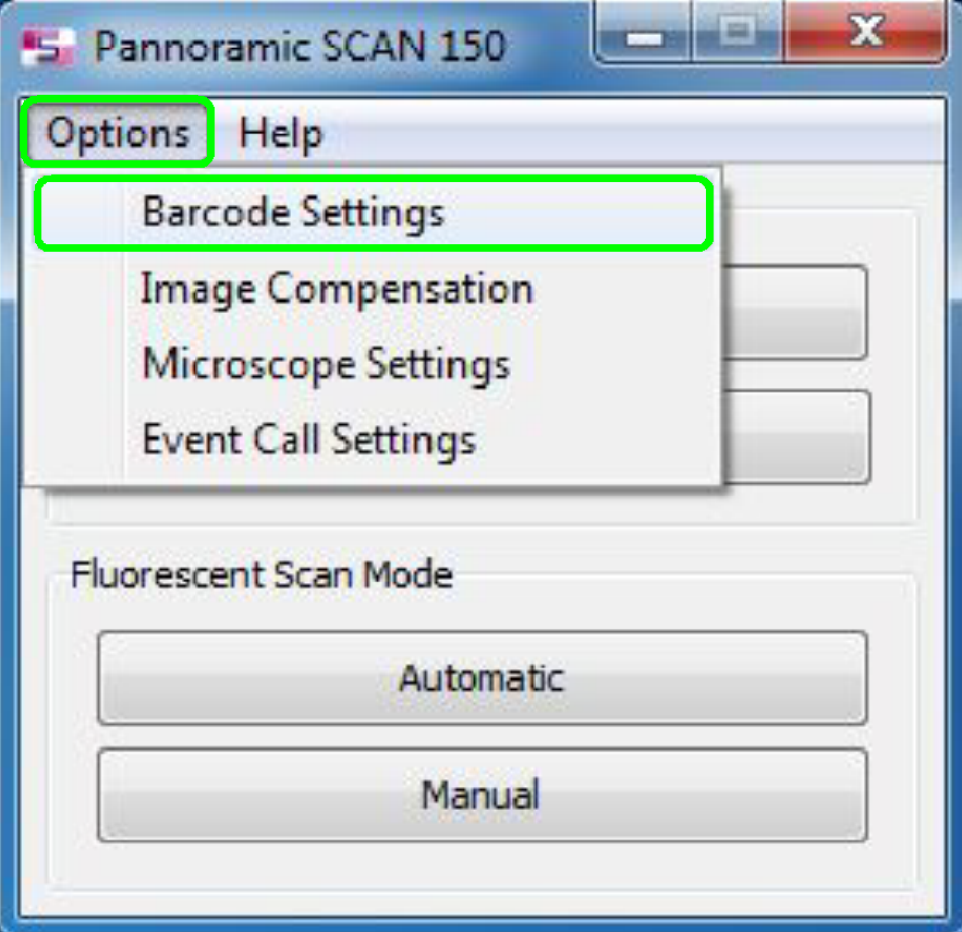
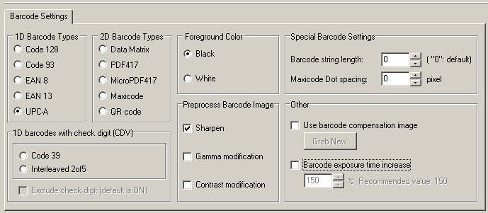
The following dialog is implemented since the
version 1.11 in the program “SlideScanner.exe” and can be found in
“Options”, “Barcode settings”.
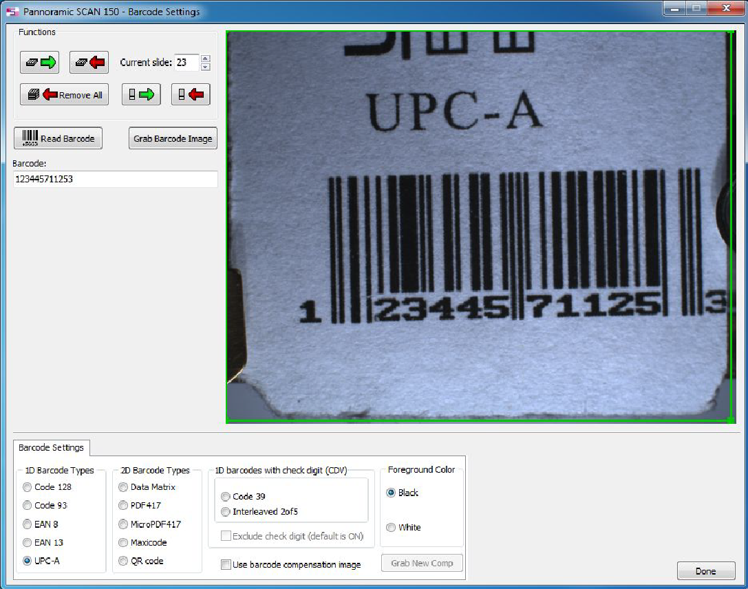
1D Barcode Types, 2D Barcode Types
Check the appropriate radio button for the barcode
type you are expected to read. In the file “Barcode print check.pdf”
you will find enclosed the barcode set and you can compare the view of barcode
to the samples.
 1D
Barcodes with check digit
1D
Barcodes with check digit
This barcodes including a check of correct reading the
barcode and this is added as a digit of the barcode (always the last character
position). With checked checkbox “Exclude check digit” this check digit is not
displayed and is also not a part of the read barcode. For test possibilities
you can uncheck this checkbox, the check digit will be displayed and is a part
of the read barcode.
Fore ground color
The foreground color is black. If the barcode is
reverse printed (white barcode on black background) select the foreground color
as white.
Preprocess Barcode Image
Sharpen
The sharpness is calculated meanwhile the barcode
image is taken.
Gamma modification
A slider will be opened and you can adjust a value for
gamma in the range of
Contrast modification
A slider will be opened and you can adjust a value for
contrast in the range of
Special Barcode Settings
Barcode string length
You can define a string length, coded in the barcode.
This way, the barcode detection will be quicker. If the number of
coded characters in the barcode and the number of characters to be read defined
here is not identical, an error message occurs, “There is no barcode”. If zero
is selected (default) any string length can be read.
Maxi code dot spacing
The dot spacing for the dots in the maxi code can be
defined. Maxi code barcode can be created with dot spacing different from the
default value (0). For successful barcode decoding this dot spacing value must
be defined here.
Other
Use barcode compensation Image
This is one of two possibilities to increase the
readability of barcodes. The compensation image, taken with the “Grab New”
option is used to compensate the barcode image for best barcode decoding
results. The image is stored and will be used until this checkbox is checked.
Grab New
A new compensation image is taken of the barcode area
and will be stored; the previously took compensation image will be overwritten.
It is important, that an exact white (not light gray) area is inserted and the
surface should be very smooth. An only white paper surface is too rough.
Barcode exposure time increase
This is another possibility to increase the
readability of barcodes. Because the automatically calculated exposure time
often produces a too dark view of the barcode area, you can increase the
brightness of the view; and so you increase the readability of barcodes. The
calculated exposure time reflects to the value of 100 percent. To find a well
usable value for the exposure time, the start value of 100 percent should be
increased by a step rate of 10 percent until the optimum was found.
Check barcode reading with different barcodes and types
Now we are checking the readability of defined
barcodes. For this purpose a set of barcodes is required that fulfill the
requirements in pixel size and mechanical dimensions for the smallest, readable
barcodes. In the appendix you find a set of barcodes for testing. If this page
is printed onto an adhesive label sheet and each label is stuck on a slide, you
created your own barcode test set. For further details see the appendix. After
all these barcodes are recognized successfully by the Matrox Imaging
Library, check some samples of the user’s unreadable barcodes. See also chapter
“7 Barcodes in practice”.
1. Start
the program “SlideScanner.exe” and in the tab “options” of the first selector
screen select the option “Barcode Settings”.
2. Insert
a slide with barcode.
3. In the
selector guide “Barcode settings” select the barcode type to be decoded. The
type, shown on the slide label and selected in the “Barcode settings” must be
equal.
4. Press
the button “Read barcode”.
5. The
software starts the barcode reading and decoding, the result is written in the
field below the button “Read barcode”. If the barcode can not be decoded in 5
attempts the error message “There is no barcode” is displayed.
Attention:
Some 1D barcodes can be read with different types and the contents of
the barcode is different also. To achieve the correct barcode content select
always the appropriate barcode type in “barcode settings”!
1. Repeat
steps 2 to 4 with all slides of the barcode check set.
2. Read
barcodes from the users “Hard to read” collection.
The following examples show barcodes, coded
with Data-matrix. The left hand column shows the original barcode area of
the slides and on the right hand column you find the same slide as it is seen
by the preview camera for barcode analyzing and decoding. In the following we
analyze the barcode print. Slides with visible faults in the barcode should be
excluded from the tissue creation process. All the following barcode prints was
read with the same illumination setup. Unreadable barcode prints could also not
be read after illumination modifying. To ensure a high print quality and to
increase the readability of the barcode the slide’s barcode area should be
clean and dry, free of moisture, before printing. The printers, even ink jet
printers should be maintained in the defined time interval and the ink
cartridge should be changed if the “ink low” message occurs. Ink jet printers
have often an integrated service part with a “Clean” option in their drivers.
Run the “clean” and “Test print” options if the print quality is reduced.
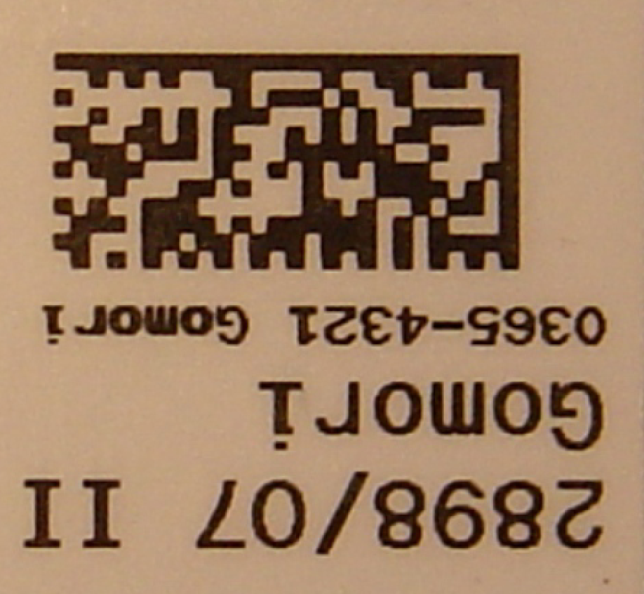
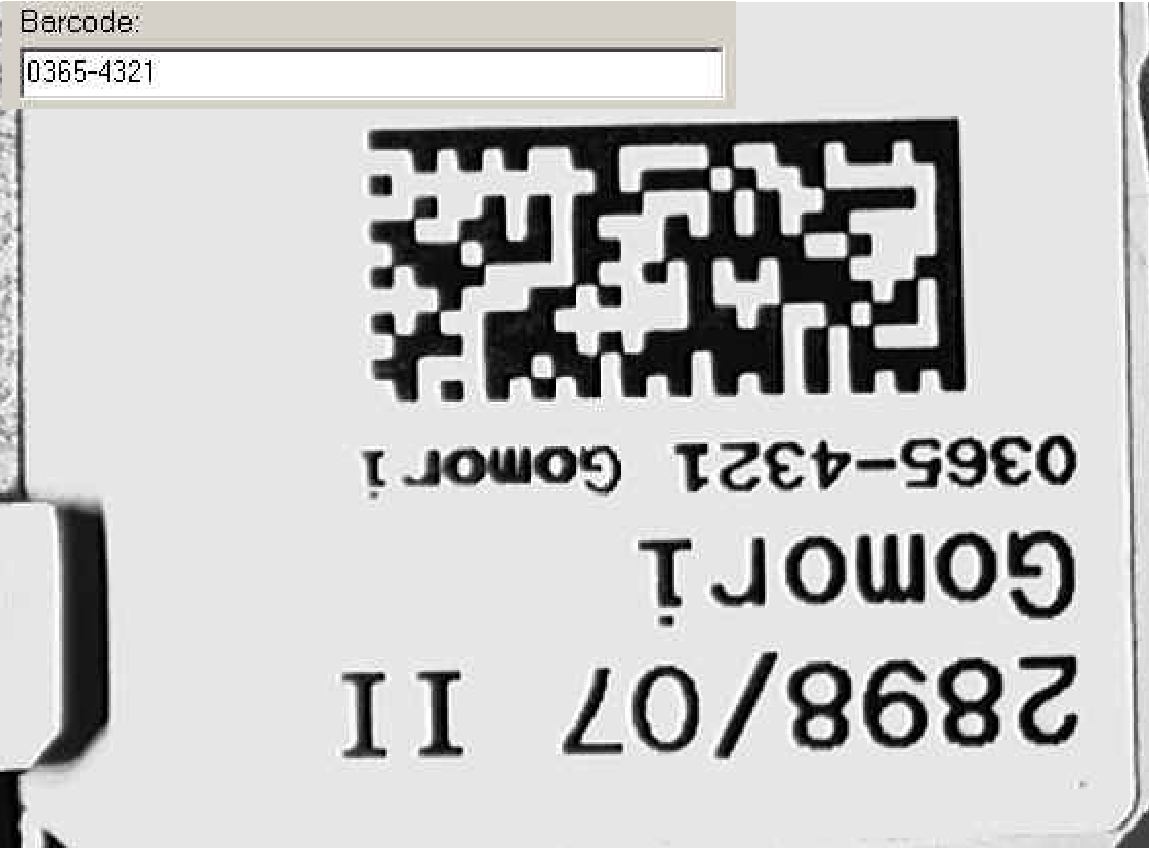
Figure 1: The
slide has a LASER printed barcode paper label. A good solution, the barcode
print is rich in contrast and therefore easily and safely readable.
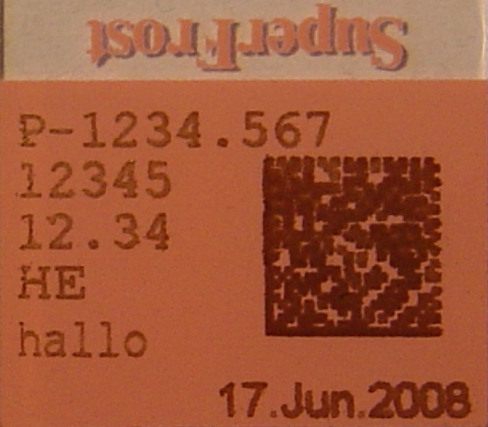
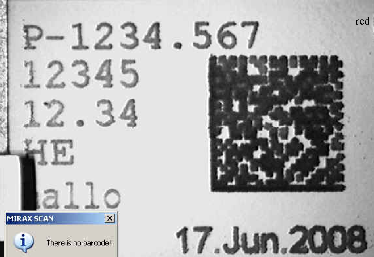
Figure 2: The
barcode was printed with an ink jet printer direct onto the surface of the
slide. May be there was too much ink, the slide was moved before the ink was
dry or moisture is on the barcode area meanwhile printing. Contrast poor,
blurry or diffuse barcode print is unreadable.
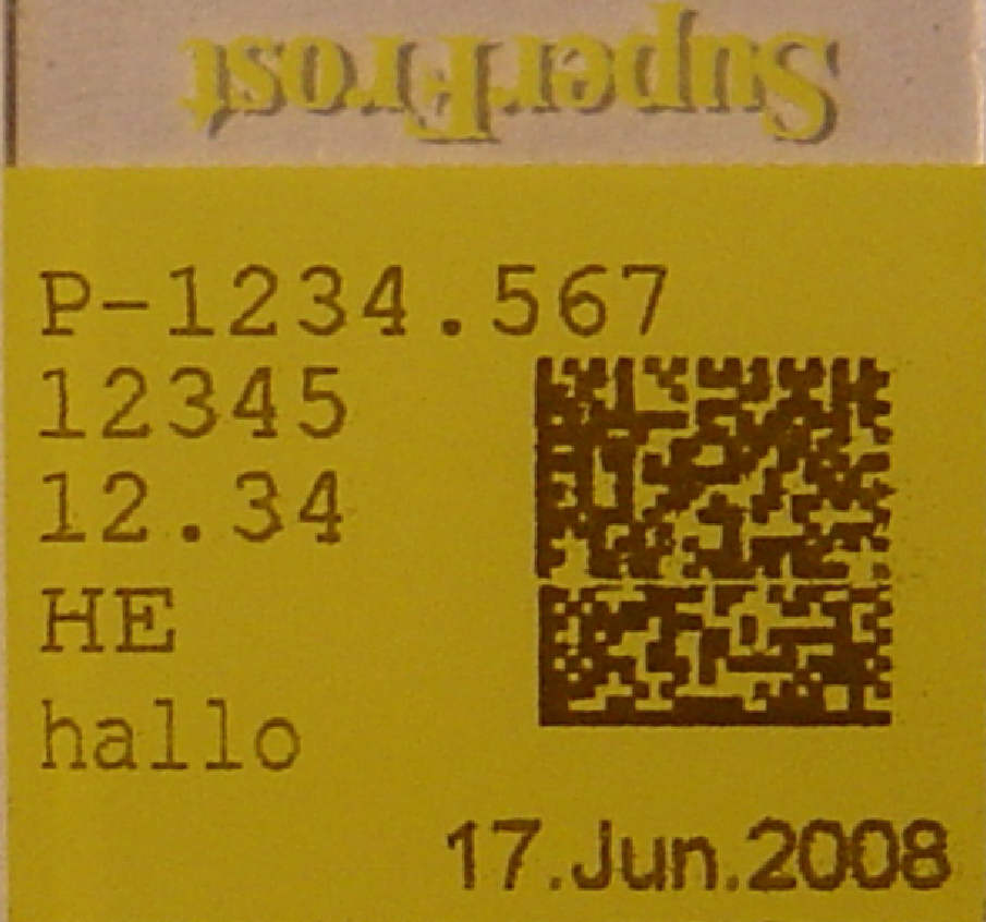
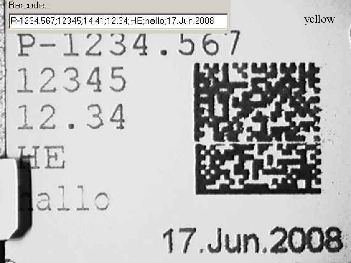
Figure 3: The
barcode was printed with an ink jet printer direct onto the surface of the
slide. A nozzle does not work during printing. A missed jet in the print may be
readable or not, it depends on the position, where the jet is lost. Maintain
the printer.
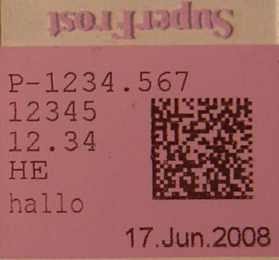
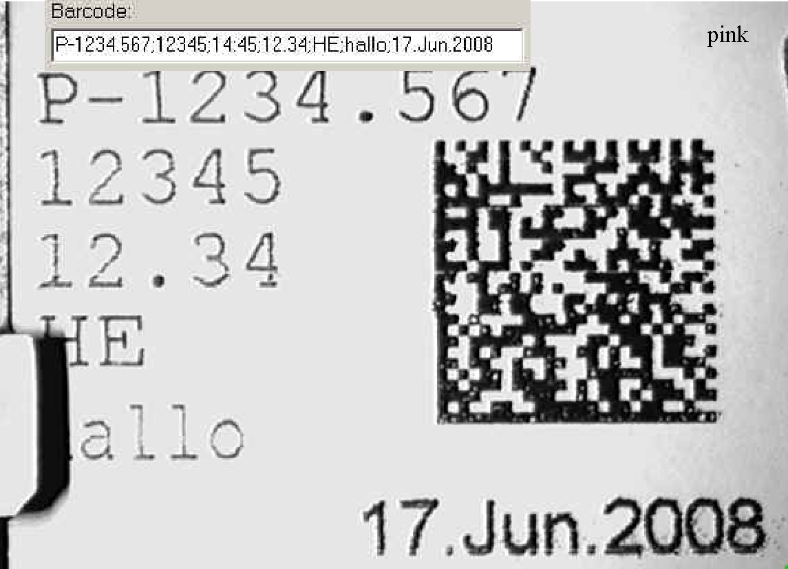
Figure 4: The
barcode was printed with an ink jet printer direct onto the surface of the
slide. Some jets have not enough ink, so the contrast is partially reduced. A
contrast reduced print may be readable or not. Maintain the printer and / or
change the ink patron earlier.
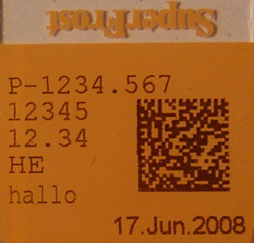
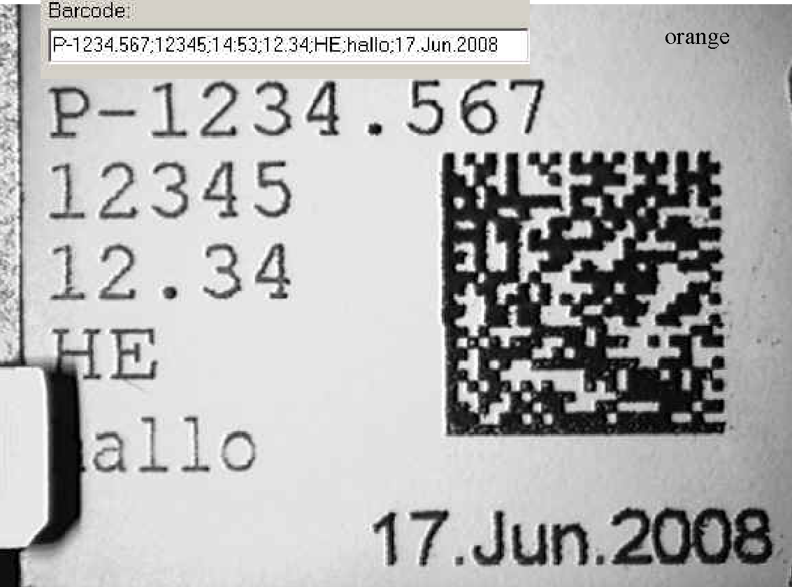
Figure 5: The
barcode was printed with an ink jet printer direct onto the surface of the
slide. Some jets have not enough ink, so the contrast is partially reduced. A
contrast reduced print may be readable or not. Maintain the printer and / or
change the ink patron earlier.
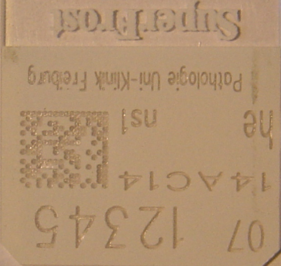
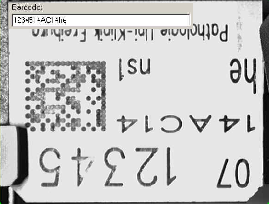
Figure 6: The
barcode is engraved by a LASER beam. The contrast is reduced because a white
surface (=background) is “printed” (as a result of engraving) with glass, so
the contrast cannot be much. This barcode needs very uniform adjusted
illumination, exact adjusted white balance and shutter values.
Appendix
Create your own barcode check set.
 In the
file “Barcode print check.pdf” you will find enclosed the barcode set. The
content of this page generates a full, specified barcode test set.
In the
file “Barcode print check.pdf” you will find enclosed the barcode set. The
content of this page generates a full, specified barcode test set.
Please print the file “Barcode print check.pdf”
perhaps with a LASER printer onto an adhesive label sheet with 27 labels
organized as 3 columns with 9 lines of labels, the upper border is 5
mm and the lower border is 3 mm, with no border on the left and no
border on the right.
The size of one label is 70 mm x 32
mm without space to each other.
After printing, stick each label onto a slide and cut
it around with a utility knife.
Take into account that the slide clamp lower part
in Pannoramic SCAN cuts out a bit of the barcode area. The shadow
should not disturb the barcode print.
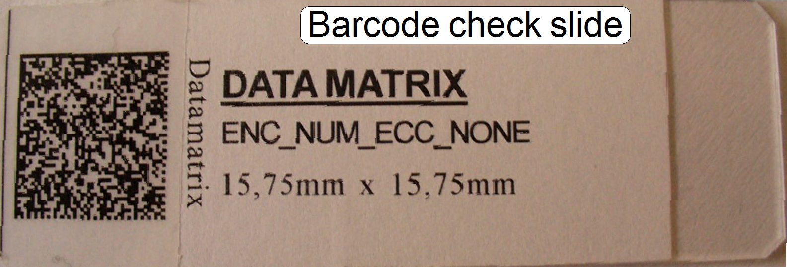 To prevent the barcode print from dust and
finger prints during use, stick a strip “tesa Film crystal clear” 19
mm in with or equivalent translucent strip over the barcode print; so it
becomes cleanable. If the adjustments are correct and no mistake occurred
meanwhile creation, all this barcodes are readable; even if the label is
stacked on slanted.
To prevent the barcode print from dust and
finger prints during use, stick a strip “tesa Film crystal clear” 19
mm in with or equivalent translucent strip over the barcode print; so it
becomes cleanable. If the adjustments are correct and no mistake occurred
meanwhile creation, all this barcodes are readable; even if the label is
stacked on slanted.