Prerequisites cont’d
For technicians and sales managers!
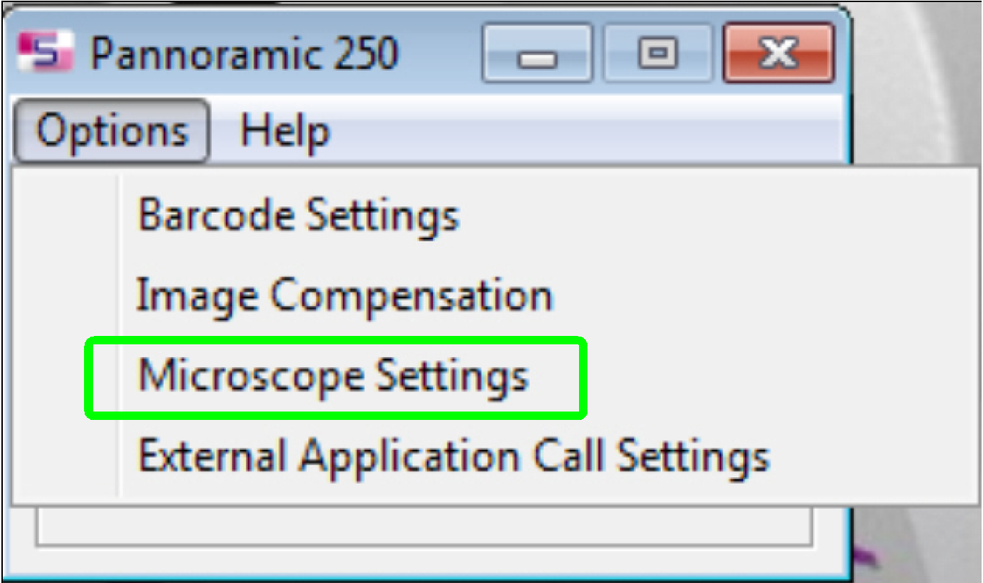 Since the software
version 1.14 usable scan cameras as well as other settings of the scanner are defined
in the dialogue “Microscope settings” in the menu “Options” of the selector
dialogue.
Since the software
version 1.14 usable scan cameras as well as other settings of the scanner are defined
in the dialogue “Microscope settings” in the menu “Options” of the selector
dialogue.
Adimec
Q-12A180 CXP
All cameras with “CL” (Camera Link interface) in the name will be
handled via the SOLIOS or the RADIENT board!
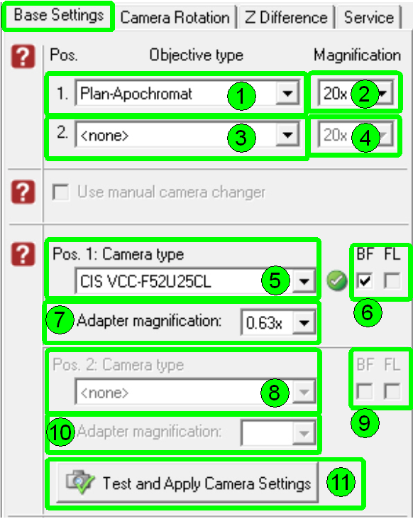
“Base Settings”
 All hardware
(camera implementation or exchange) and driver modifications have to be done
prior to starting the program SlideScanner.exe and the dialogue “Base
Settings”; the driver have to be already installed, the camera have to be
connected and powered on!
All hardware
(camera implementation or exchange) and driver modifications have to be done
prior to starting the program SlideScanner.exe and the dialogue “Base
Settings”; the driver have to be already installed, the camera have to be
connected and powered on!
The objective settings should
be done or checked together with the setup of the camera(s); the items (1) to
(4).
![]() “Setup and define
implemented objectives”
“Setup and define
implemented objectives”
Pos.
1: Camera type (FL-camera)
By opening the pull down menu (5) one of the implemented cameras can be
selected. The selected camera type has to be identical with the connected
camera type.
If the Pannoramic
scanner is equipped with a camera changer unit, the fluorescent scan camera has
to be defined here.
If the 90º camera tube
is installed, the brightfield camera has to be
defined here.
![]() “Camera positions on the camera
changer”.
“Camera positions on the camera
changer”.
BF
Check this checkbox (6), (9) if the selected camera should be used for brightfield scan.
FL
Check this checkbox (6), (9) if the selected camera should be used for
fluorescent scan.
Check both checkboxes if the
camera should be used for BF and FL scan operation (if only one camera is
installed or for test purposes).
Adapter
magnification
Select the real value for the camera adapter magnification (7), (10); it
can be found on the
camera adapter itself.
Pos.
2: Camera type (Brightfield camera)
If the Pannoramic scanner is equipped with a
camera changer unit the brightfield camera has to be
defined here. The camera, defined for position 1 will be excluded from the list
of this pull down menu. Furthermore, if the position 1 camera was defined as FL
scan, the position 2 camera can be defined for BF scan only and vice versa (8).
![]() “Camera positions on the camera
changer”.
“Camera positions on the camera
changer”.
Test
and Apply Camera Settings
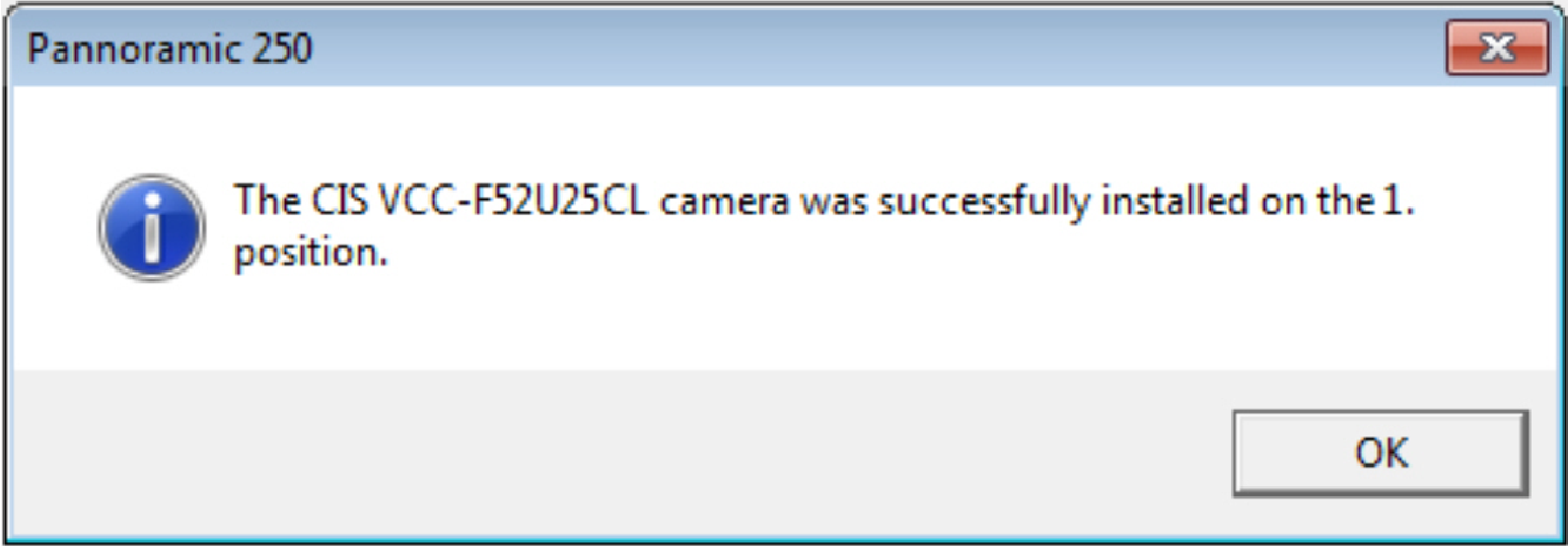
The defined camera type(s) will be checked for system integrity (11). If
the result of the check is positive, the camera types are accepted and are
integrated into the system; the success is shown with a “![]() ”
mark beside the selected camera type. An information window shows the result of
the check.
”
mark beside the selected camera type. An information window shows the result of
the check.
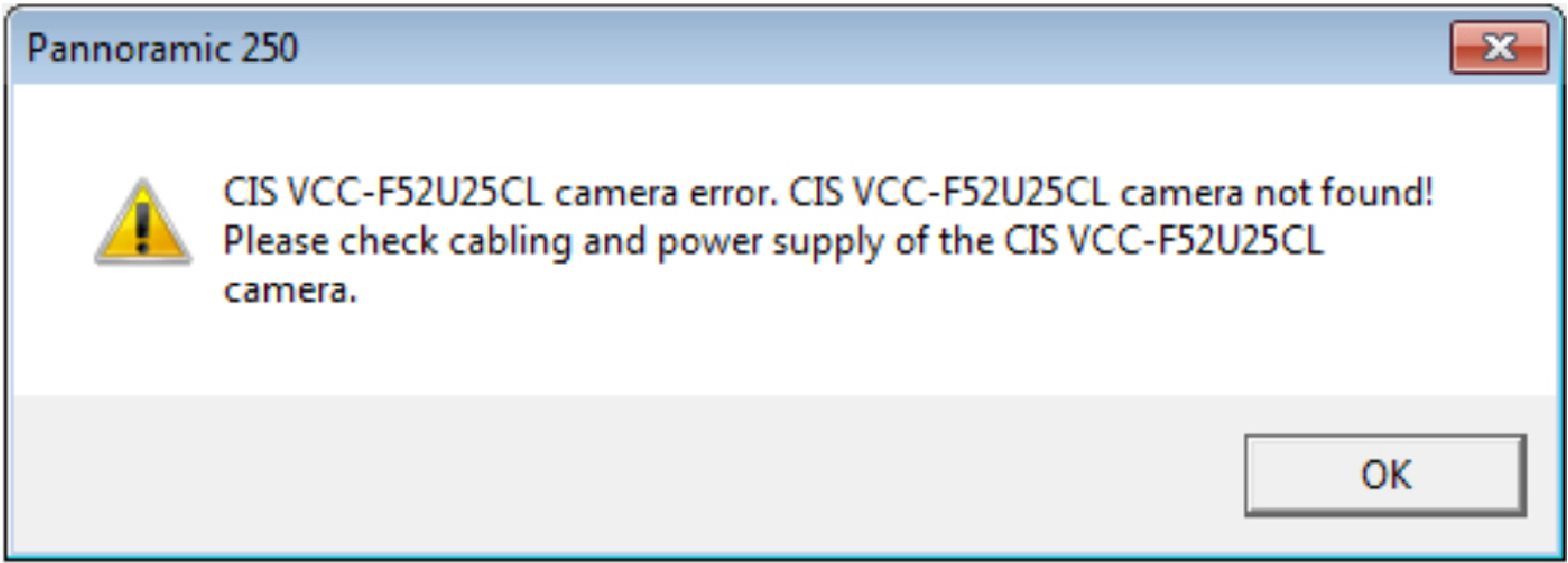
If there is trouble with any
selected camera an error message occurs; the unsuccessful integrity is shown
with a “![]() ”
mark.
”
mark.
![]()
Success of camera integrity check
![]()
Camera integrity check failed
If the camera integrity check has failed
Check the Camera Link
connection between Solios board and camera; the
cables should be connected to the appropriate port (connector) and the lock
bolts should be tightened on all four headers.
·
Check the power of the camera; the power connector
should be connected well; the camera should be switched on.
·
Check the enable or disable state of the “Power
distribution and switch board” in the file “MicroscopeConfiguration.ini” or
check the external power supply (if present).
Check the correct power
connector position on the “Power
distribution and switch board”.
·
Check the trigger cable and its connection between
camera and “X-Y-Z-ND
motor & flash light control” electronics; the trigger connector should
be connected right.
·
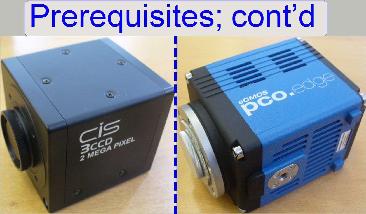
See also: “Camera
CIS-VCC-F52U25CL” and “Camera pco.edge”
respectively
Check the port (cable
connection and power supply) of the failed camera, the installation of the
MIL_9.0 or the driver
installation.
Important
If the switch “TRG” or “Vref” of the flash light
source is not set to “External” the camera installation may be not finished
correctly in the dialog “Microscope settings” or the scan program fails the
camera installation with the error message.
Following tables summarizing parameters of the preview and scan cameras in
optical aspects for scanning purposes.
|
Preview cameras |
||||
|
Camera |
Effective pixel array size |
Active pixel size |
||
|
(H) pixels |
(V) pixels |
(H) µm |
(V) µm |
|
|
2056 |
1544 |
3.2 |
3.2 |
|
|
Used: |
2048 |
1536 |
3.2 |
3.2 |
|
640 |
480 |
5.6 |
5.6 |
|
Preview camera pixel view = (Preview
camera pixel size) * (Preview objective magnification)
Preview objective magnification DFK 21F04 ~ 8.2x
Preview objective magnification VRmagic ~
4.7x
·
Preview camera pixel view DFK 21F04 = 46µm
·
Preview camera pixel view VRmagic
= 15µm
|
Useable magnifications
and resulting resolutions of scan (main) cameras |
|||||||||||
|
Camera |
Pixel array size used ; [Pixels] |
Pixel size [µm] |
Useable Magnification; Resolution [µm] |
||||||||
|
Active |
Valid |
0.63x |
1.0x |
1.6x |
|||||||
|
(H) |
(V) |
(H) |
(V) |
(H or V) |
20x |
40x |
20x |
40x |
20x |
40x |
|
|
2448 |
2048 |
3.45 |
3.45 |
4.87* |
0.39 |
0.19 |
0,24 |
0.12 |
X |
X |
|
|
1380 |
1030 |
4.65 |
4.65 |
6.58* |
0.52 |
0.26 |
0.33 |
0.16 |
X |
X |
|
|
Marlin* 1) |
1368 |
1024 |
4.65 |
4.65 |
6.58* |
0.52 |
0.26 |
0.33 |
0.16 |
X |
X |
|
4096 |
3072 |
5.5 |
5.5 |
7.78* |
X |
X |
X |
X |
0.24 |
0.12 |
|
|
1624 |
1224 |
4.40 |
4.40 |
4.40 |
0.35 |
0.18 |
0.22 |
0.11 |
X |
X |
|
|
2048 |
2048 |
5.5 |
5.5 |
7.78* |
X |
X |
0.39 |
0.19 |
0.24 |
0.12 |
|
|
1360 |
1024 |
4.65 |
4.65 |
4.65 |
0.37 |
0.18 |
0.23 |
0.12 |
X |
X |
|
|
Sony DFW-X710*
1) |
1024 |
768 |
4.65 |
4.65 |
6.58* |
0.52 |
0.26 |
0.33 |
0.16 |
X |
X |
|
Monochrome scan cameras (FL or RGB illuminated) |
|||||||||||
|
2448 |
2048 |
3.45 |
3.45 |
3.45 |
0.27 |
0.14 |
0,17 |
0.08 |
X |
X |
|
|
1388 |
1040 |
6.45 |
6.45 |
6.45 |
X |
X |
0.32 |
0.16 |
X |
X |
|
|
2048 |
2048 |
6.5 |
6.5 |
6.5 |
X |
X |
0.32 |
0.16 |
X |
X |
|
|
PCO-edge 5.5_@
2.5Mp |
1600 |
1600 |
6.5 |
6.5 |
6.5 |
X |
X |
0.32 |
0.16 |
X |
X |
|
PCO-edge 5.5_@
4.0Mp |
1920 |
1920 |
6.5 |
6.5 |
6.5 |
X |
X |
0.32 |
0.16 |
X |
X |
|
PCO-edge 5.5_PCON |
2560 |
2160 |
6.5 |
6.5 |
6.5 |
X |
X |
0.32 |
0.16 |
X |
X |
X)
Not defined, can not be used
* Calculations for
these cameras are done by using the factor sqrt(2)
Resolution [µm] = (Active camera pixel size * sqrt(2) )
/ (objective magnification * camera adapter magnification); used if single chip
camera with Bayer method
· sqrt(2)= required,
because debayering (creation of color information in
single chip cameras with Bayer
method); and generation of JPEG file
If real color camera or monochrome (FL)
camera:
Resolution [µm] = (Active camera pixel size) / (objective
magnification * camera adapter magnification)
1) No longer delivered
2) Useable since SW
version 1.20 only!
3) Useable since SW
version 1.21only!
![]() Rolling shutter vs. Global
shutter
Rolling shutter vs. Global
shutter
Scan
cameras for Pannoramic digital slide scanners
Used in: P250 FLASH 3, SW-version
1.20 and higher
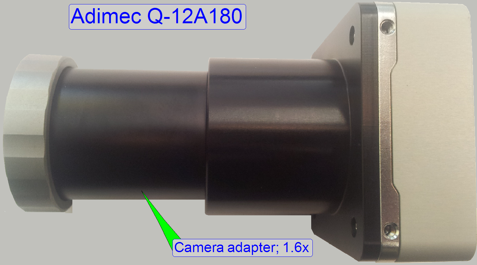 The Adimec
QUARTZ Q-12A180 is a12 Megapixel camera at 187 fps with a maximum of only 9W
power consumption in a small outline; with the highest image quality today and
the QUAD CoaXPress interface.
The Adimec
QUARTZ Q-12A180 is a12 Megapixel camera at 187 fps with a maximum of only 9W
power consumption in a small outline; with the highest image quality today and
the QUAD CoaXPress interface.
Sensor
· Type: CMV12000
LINK
·
Global shutter CMOS
·
A/D conversion 32 channels 8 or 10bit ADC
·
 Optical size APS-C
·
Resolution 12MPixels - 4096(H) x 3072(V)
·
Pixel size 5.5 x 5.5 μm
·
Active
pixels 4096
(H) x 3072 (V)
· Frame rate 300 fps (10 bit)
132
fps (12 bit)
·
Chroma Mono, Mono NIR enhanced and
RGB
Triggering Internal or external
Power Input 24Vdc PoCXP
(Power over CXP)
Operating temperature
Interface CoaXPress; Configurable 1, 2 or 4 lanes
Board: Matrox Radient eV-CXP; PCIe 2.0 x8, PoCXP
![]() Rolling shutter vs. Global
shutter (stored); Useable
magnifications and resulting resolutions of scan cameras
Rolling shutter vs. Global
shutter (stored); Useable
magnifications and resulting resolutions of scan cameras
![]() ”Specifications”
(stored); “CoaXPress”; “Multyway-connector” (stored); “Matrox_Radient_ev_cxp.pdf”
(stored)
”Specifications”
(stored); “CoaXPress”; “Multyway-connector” (stored); “Matrox_Radient_ev_cxp.pdf”
(stored)
Image
sensor CMV12000 ©AMS (stored)
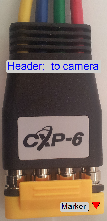
![]()
If the LED of any wire is flashing red, then the appropriate line is not
recognized or not connected or the line is not controlled yet by software!
Power
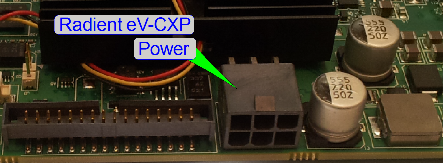 The power for the
camera is provided over the CXP cables
The power for the
camera is provided over the CXP cables
Important
To provide power for the camera the internal power connector of the Radient eV-CXP board has to be
connected with the power supply!
Cabling
See the images on the right
If the LED of any wire is flashing red, then the appropriate line is not
recognized or not connected or the line is not controlled yet by software!
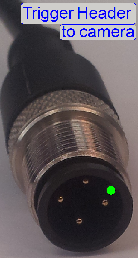
Trigger
Camera
adapter
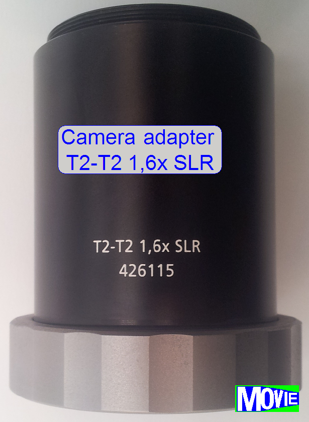
Because the camera Adimedc has a very large
CMOS sensor, the camera is always used with a camera adapter of 1.6x
Manufacturer: POINTGREY
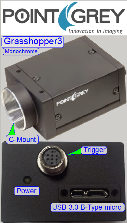
 Model: GS3-U3-51S5 M-C;
monochrome and
Model: GS3-U3-51S5 M-C;
monochrome and
GS3-U3-51S5
C-C; Color
Monochrome
version used in: delivered
S_M_D_II type scanners since summer 2016 as BF and FL scan camera or in other
scanner types as FL scan camera
Color version used in: scanner types, delivered before summer 2016,
as BF scan camera (momentarily not used; not implemented)
SW Version: 1.21
or higher.
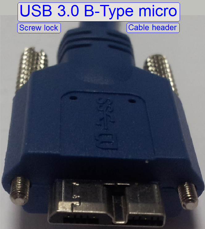
Interface type: USB
3.0
Power: Supplied
over USB 3.0 or external; 4.5W max.
The Grasshopper3 is an USB 3.0 interfaced monochrome scan camera, used
mainly in improved SCAN,
The camera requires the software version 1.21. Because improved S_M_D
type scanners got an RGB brightfield scan
illumination unit, the FOV is captured three times, one time by each
color. The 3 gray scale images, taken by
the Grasshopper3 monochrome camera, define the partial intensity of the
appropriate color. By assembling the raw RGB images and using the software
coloring method, images of a very high quality and color fidelity with improved
resolution can be produced.
The color version of the camera may be used in upgraded Pannoramic type scanners with Halogen lamp BF illumination;
it offers higher pixel resolution and higher image transfer speed.
Improvements
·
Only one camera is required for BF and FL scan
sessions
·
Camera changer unit not required
·
Higher scan quality, faster scan speed
·
Higher pixel resolution
·
10 times faster image transfer over USB3.0 (in
relation to Stingray camera)
|
Features; GS3-U3-51S5 |
||
|
Parameter |
M-C (mono) |
C-C (color) |
|
Resolution (H x V) |
2448 x 2048 |
2448 x 2048 |
|
Pixel Size |
3.45 µm |
3.45 µm |
|
Megapixels |
5.0 MP |
5.0 MP |
|
Chroma |
Mono |
Color |
|
Sensor Name |
Sony IMX250 |
Sony IMX250 |
|
Sensor Type |
CMOS |
CMOS |
|
Readout Method |
Global shutter |
Global shutter |
|
Sensor Format |
2/3" |
2/3" |
|
Frame Rate |
75 FPS |
75 FPS |
|
Lens Mount |
C-mount |
C-mount |
|
ADC |
10-bit or 12-bit |
10-bit or 12-bit |
|
Interface |
USB 3.0 |
USB 3.0 |
![]() POINTGREY
home page
POINTGREY
home page
Getting started manual (stored)
Technical Reference
(stored)
Imaging Performance
(stored)
Data sheet (stored)
Getting started manual (stored)
Rolling shutter vs. Global
shutter (stored); Useable
magnifications and resulting resolutions of scan cameras
Important
Please use always a FRESCO FL 1100 USB 3.0 interface board, type
U3-PCIE1XG211 to interfacing Grasshopper3 type cameras in Pannoramic
Scanners.
·
By using other USB 3.0 interface ports, the camera
might not work.
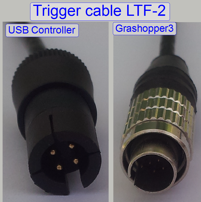
Trigger
HW triggering
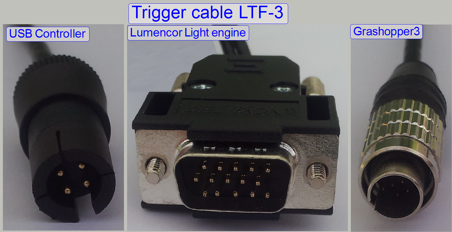
 If an RGB brightfield illumination unit is used and the camera works
as BF scan camera (S_M_D), the camera will be triggered by the trigger output
of the scanner.
If an RGB brightfield illumination unit is used and the camera works
as BF scan camera (S_M_D), the camera will be triggered by the trigger output
of the scanner.
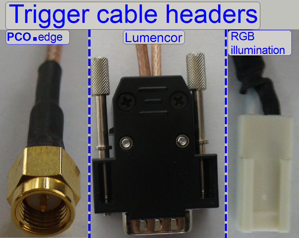
Two types of trigger cable are used:
LTF-2: The
scanner’s USB control electronics triggers the camera
LTF-3: The scanner’s USB control
electronics triggers the camera and the lumencor
spectra light engine©
SW triggering
If the camera works as FL scan camera in scanners with camera changer,
the camera will be triggered by software.
Driver setup
Used in: P250, SCAN,
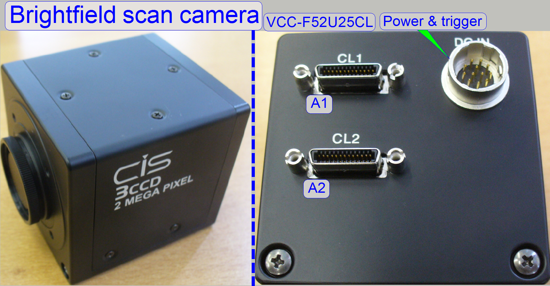
The VCC-F52U25CL is a
camera link interfaced, 3CCD high-resolution industrial color video camera
module utilizing a 1/1.8 type PS IT CCD. The 2M pixels CCD image sensor with
on-chip micro-lenses realizes high sensitivity and high resolution. The full
size field of view can be read out within approx. 30fps.
CIS-
VCC-F52U25CL
Device Type: 1/1.8 type Interline
Transfer Color CCD
![]() CCD/sCMOS: SONY ICX274AL
CCD/sCMOS: SONY ICX274AL
Effective Pixel Number: 1628 (H) × 1236 (V)
Unit Cell Size: 4.40μm (H) × 4.40μm
(V)
Chip Size: 8.50mm (H) × 6.80mm
(V)
![]() “Possible scan modes with different cameras and
magnifications in the software version 1.16; 1.17beta and 1.17
“Possible scan modes with different cameras and
magnifications in the software version 1.16; 1.17beta and 1.17
“Useable magnifications
and resulting resolutions of scan cameras”
Further
information about features, precautions and detailed technical information can
be found in the file “vcc-f52u25cl_en.pdf”.
![]() Rolling shutter vs. Global
shutter (stored)
Rolling shutter vs. Global
shutter (stored)
Power
The camera gets its power of 12V-DC, 6.0W by default from the “Power
distribution and switch board” of the scanner.
The camera interface is a so called “Hot plug interface” so the cable
header may be removed or plugged during the computer is powered on, but wait
until the data transfer between camera and link board is finished (if in
progress).
Nevertheless, the camera should be powered off before any connection
modification is taken.
Unplug the power header of
the camera or switch off the entire scanner.
Make the desired connections
and secure the header connection with the lock bolts.
Switch on the scanner, or
plug the power header.
 Check the camera
integrity or implementation with the dialogue “Microscope Settings”.
Check the camera
integrity or implementation with the dialogue “Microscope Settings”.
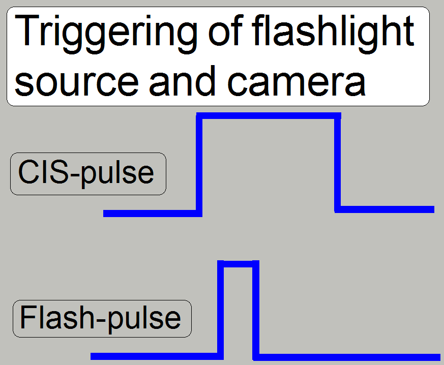
Triggering
The trigger input pulse width of the camera as well as the width of the
trigger pulse of the flash light source is controlled by the firmware. The trigger
cable of the camera is connected to the appropriate connector of the “X-Y-Z-ND motor and flash
light control” electronics.
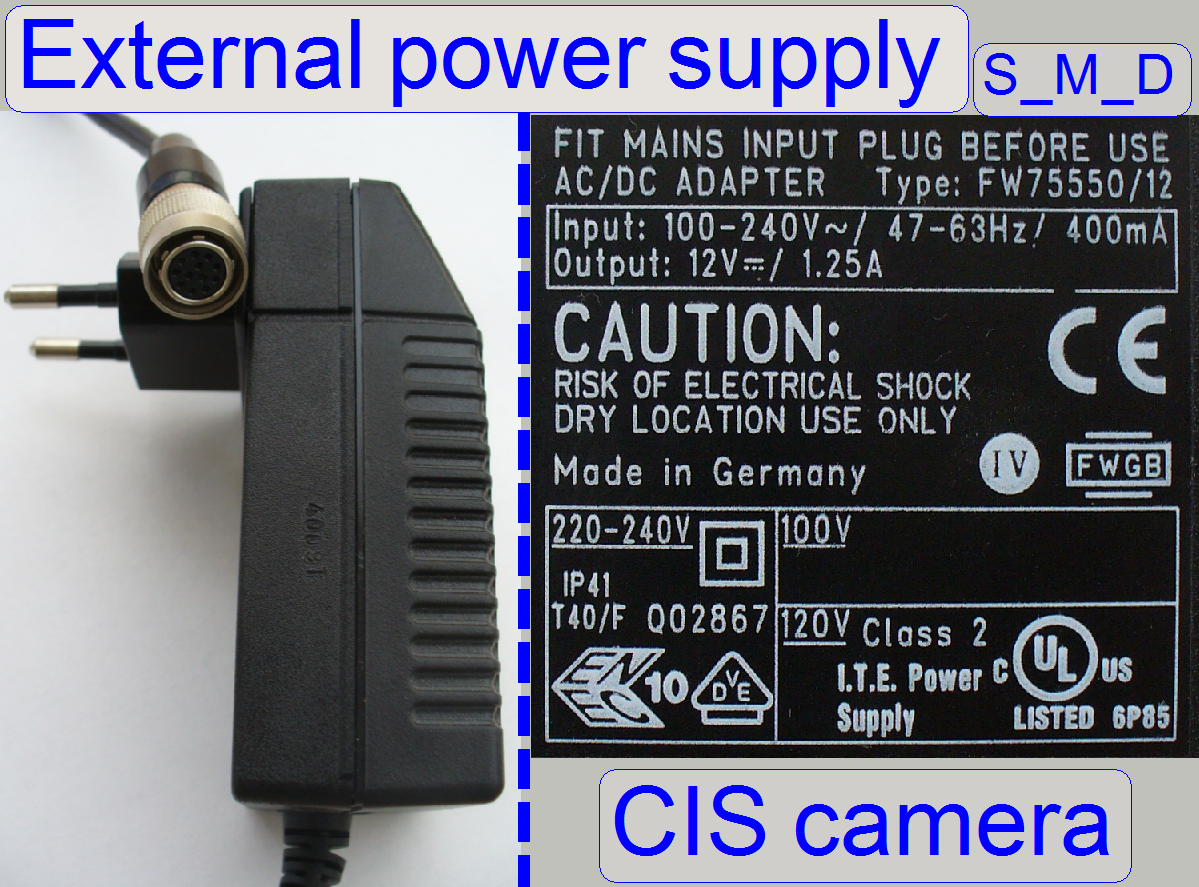 This power supply
is used if the CIS-camera works in SCAN or
This power supply
is used if the CIS-camera works in SCAN or
The timing of the camera’s
shutter in the SCAN or the
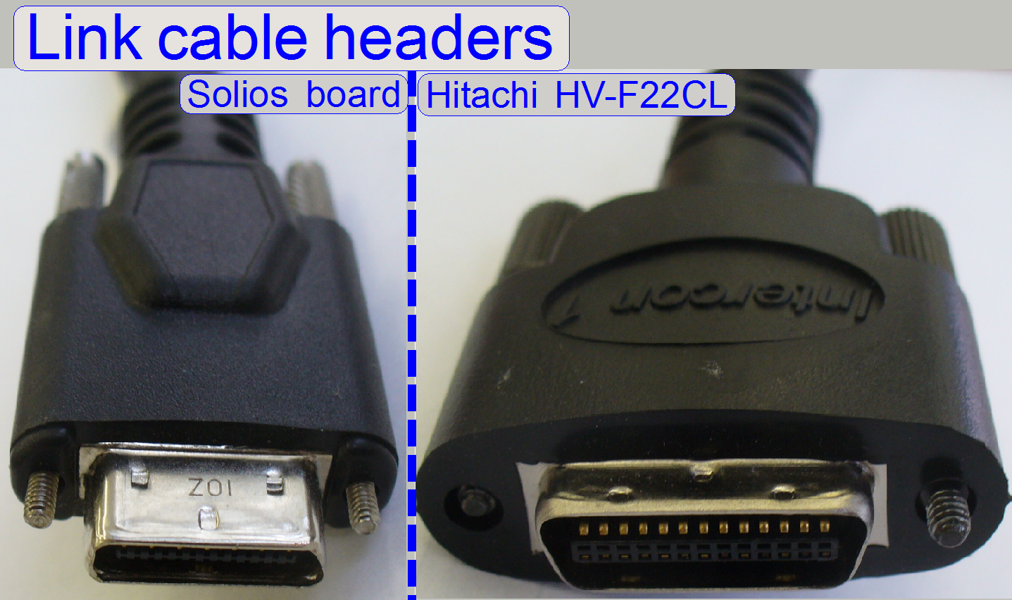
Camera Link
connection
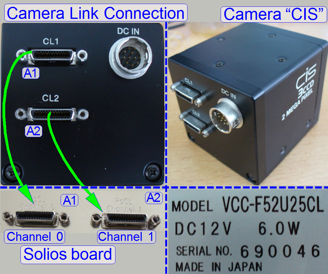
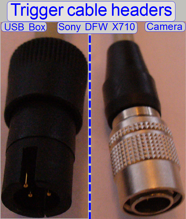
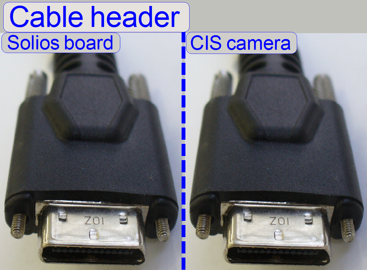 Both camera link
cables are from the same type and the headers are wired 1:1, so any cable
header can be connected to the Solios board or to the
camera as well.
Both camera link
cables are from the same type and the headers are wired 1:1, so any cable
header can be connected to the Solios board or to the
camera as well.
Important
The Camera link cable, connected to the port “CL1” of the camera have to
be connected to the “Channel
If
these conditions are not met, the camera will not be found or recognized by the
software!
Important
If the switch “TRG”
or “Vref” of the flash light
source is not set to “External” the camera installation may be not finished
correctly in the dialog “Microscope settings” or the scan program fails the
camera installation with the error message.
Driver
install
The CIS-camera is fully handled by the scan software “SlideScanner.exe”
via the Solios board; therefore, an explicit driver
installation procedure is not required.
![]() “Setup the Matrox Imaging Library version 9.0 (MIL 9.0)”
“Setup the Matrox Imaging Library version 9.0 (MIL 9.0)”
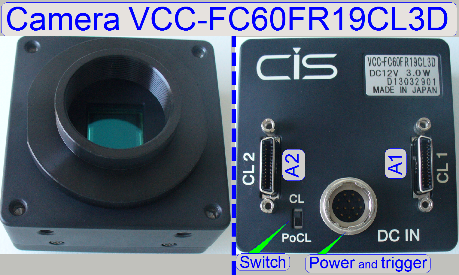
Used in: iSaCS, P250, SCAN,
The VCC-FC60FR19CL is a
camera link interfaced, 4Mpixels high-resolution industrial color video camera
module. The 4M pixels global shutter CMOS sensor realizes high sensitivity and
high resolution. The full size field of view can be read out within 135fps,
depending on the configuration.
VCC-FC60FR19CL
 Effective pixel number: 2048 (H) x 2048 (V)
Cell size: 5.5μm (H) x
5.5μm (V)
Frame rate: 68 to 135fps;
depending on configuration
![]() VCC-FC60FR19CL Product
specification and Operational Manual ©CIS-Corporation (stored)
VCC-FC60FR19CL Product
specification and Operational Manual ©CIS-Corporation (stored)
“Possible scan
modes with different cameras and magnifications in the software version 1.16; 1.17beta and 1.17
“Useable
magnifications and resulting resolutions of scan cameras”
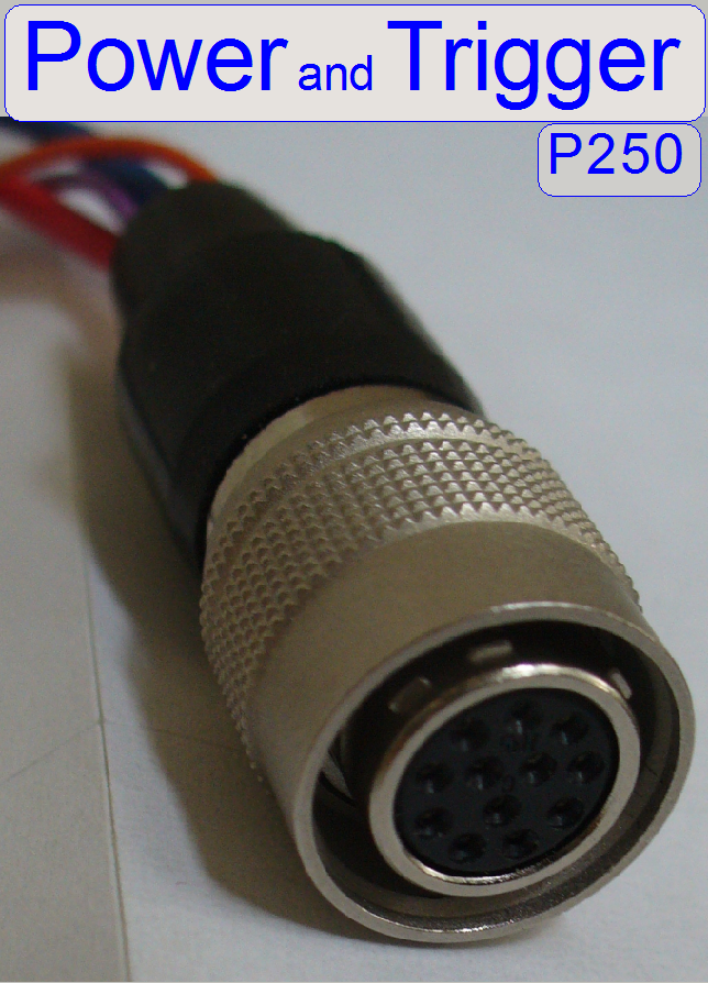
CL: In this position the power is
supplied via the “Power & trigger” connector (DC IN).
PoCL: The power is supplied via the
camera link interface (PoCL= Power over Camera Link).
Set the switch into the
position “CL” and use the power and trigger connector!
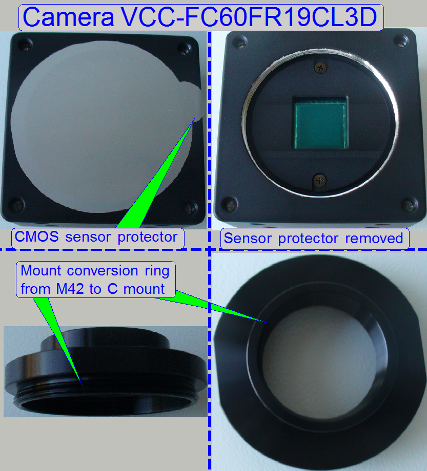
Remove
the CMOS sensor protector and mount the conversion ring.
![]() Rolling shutter vs. Global
shutter (stored)
Rolling shutter vs. Global
shutter (stored)
P250
FLASH II speed measurement
Power;
P250
The camera gets its power of 12V-DC, 3.0W by default from the “Power
distribution and switch board” of the scanner.
The camera interface is a so called “Hot plug interface” so the cable
header may be removed or plugged during the computer is powered on.
Nevertheless, the camera should be powered off before any connection
modification is taken.
Unplug the power header of
the camera or switch off the entire scanner.
Make the desired connections
and secure the header connection with the lock bolts.
Switch on the scanner, or
plug the power header.
Check the
camera migration with the dialogue “Microscope Settings”.
Power;
S_M_D
Please refer to
“External power supply”
Triggering

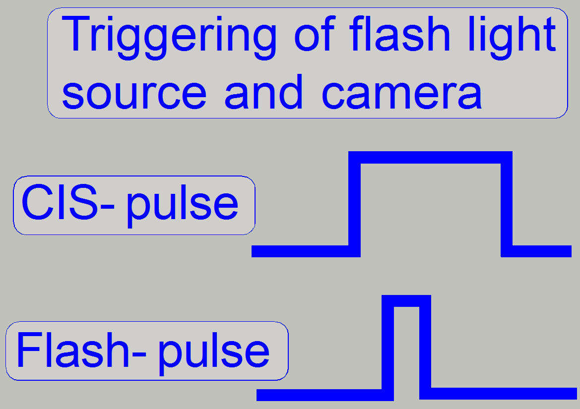 The trigger input pulse
width of the camera as well as the width of the trigger pulse of the flash
light source is controlled by the firmware. The trigger cable of the camera is
connected to the appropriate connector of the “X-Y-Z-ND motor & flash
light control” electronics.
The trigger input pulse
width of the camera as well as the width of the trigger pulse of the flash
light source is controlled by the firmware. The trigger cable of the camera is
connected to the appropriate connector of the “X-Y-Z-ND motor & flash
light control” electronics.
Camera Link connection
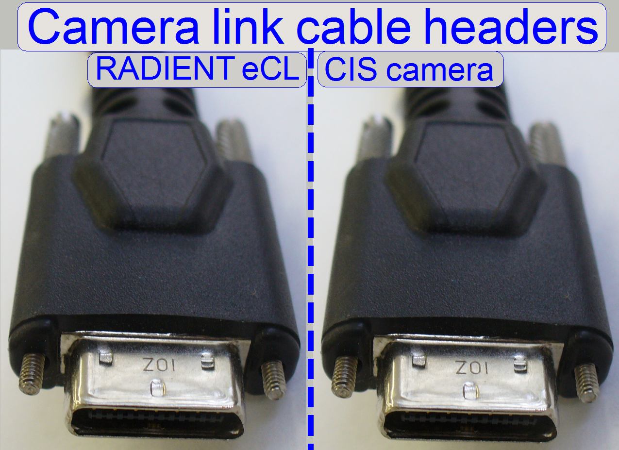 Both camera link
cables are from the same type and the headers are wired 1:1, so any cable header
can be connected to the grabber card RADIENT eCL (or
to the Solios board, if only 1 camera is used in the
scanner) or to the camera as well.
Both camera link
cables are from the same type and the headers are wired 1:1, so any cable header
can be connected to the grabber card RADIENT eCL (or
to the Solios board, if only 1 camera is used in the
scanner) or to the camera as well.
Important
The Camera link cable, connected to the port “CL1” of the camera have to
be connected to the “Channel
If
these conditions are not met, the camera will not be found or recognized by the
software!
Important
If the switch “TRG” or “Vref” of the flash light
source is not set to “External” the camera installation may be not finished
correctly in the dialog “Microscope settings” or the scan program fails the
camera installation with the error message.
Driver
install
The camera CIS is fully handled by the scan software “SlideScanner.exe”
via the RADIENT eCL board;
therefore, an explicit driver installation procedure is not required.
![]() “Setup the Matrox Imaging Library version 9.0 (MIL 9.0) Radient eCL”
“Setup the Matrox Imaging Library version 9.0 (MIL 9.0) Radient eCL”
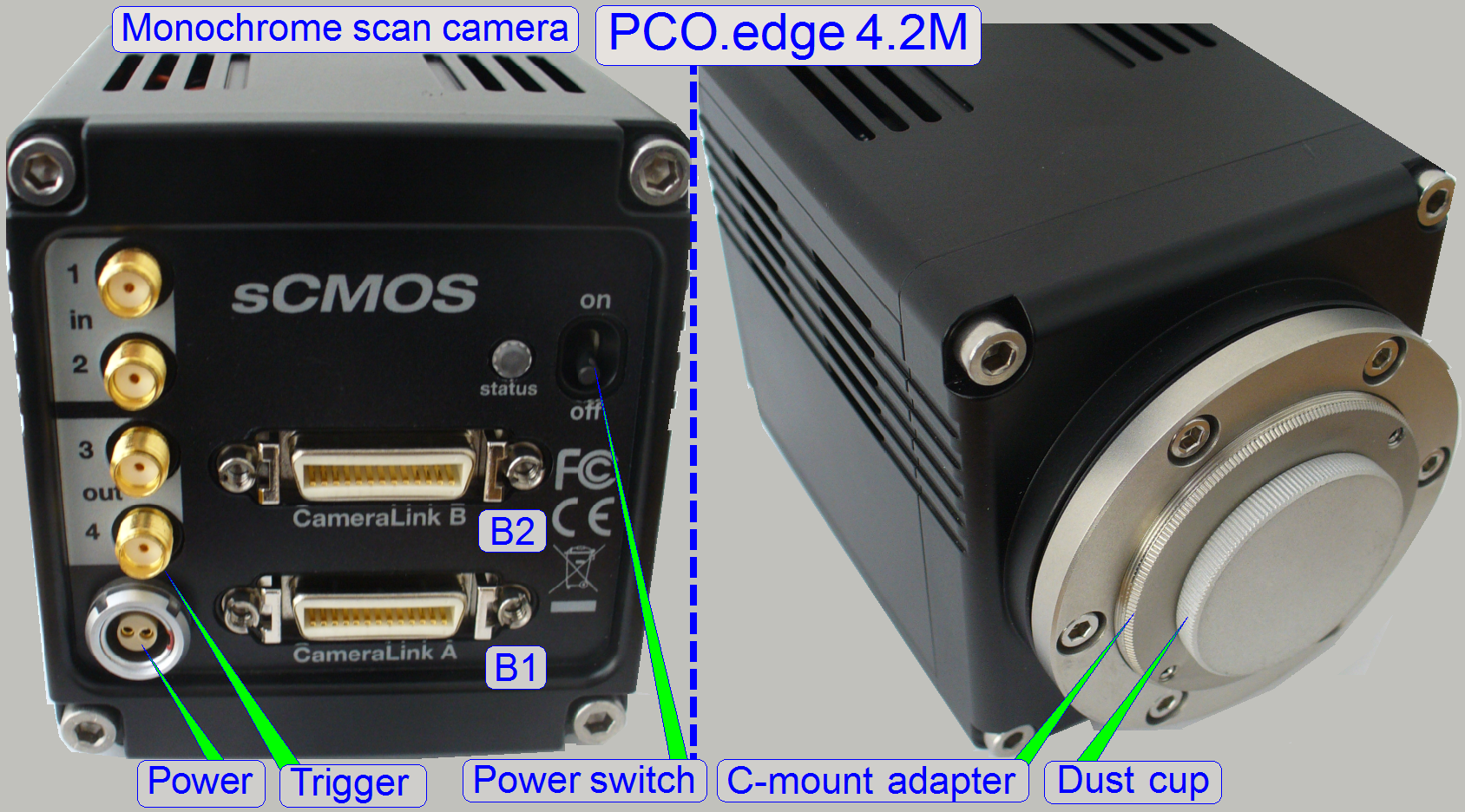
Camera
PCO-edge 5.5MP
Used in: PCON, P250, SCAN and
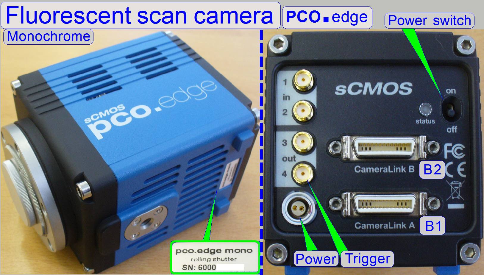
 The pco.edge
is a camera link interfaced, monochrome camera and is used for scanning of
stained tissues in the fluorescent scan mode. In the scanner type “PCON” all
scan modes are handled with this camera. The color (wave length of the light)
is defined by the used filter block and the gray scale image, taken by the pco.edge camera, defines the partial intensity. By using
the software coloring method, images of a very high quality and color fidelity
can be produced.
The pco.edge
is a camera link interfaced, monochrome camera and is used for scanning of
stained tissues in the fluorescent scan mode. In the scanner type “PCON” all
scan modes are handled with this camera. The color (wave length of the light)
is defined by the used filter block and the gray scale image, taken by the pco.edge camera, defines the partial intensity. By using
the software coloring method, images of a very high quality and color fidelity
can be produced.
Sensor: Scientific CMOS CIS2051
Resolution: 5.5Mpixels
Pixel array: 2560 (H) x 2160 (V)
Pixel size (h x v): 6.5
µm x 6.5 µm
Transfer rate: 100fps (full size)
Power
requirements
Power consumption:
20W max. (typ. 10 W @
Remark
This camera is used in some configurations with a smaller sensor size;
the size is reduced by software.
In these cases, the camera is named as
· PCO-edge_5.5_@2.5MP
and
More information about sensor
size and resolutions can be found on the shown links.
![]() “Possible scan modes with different cameras and
magnifications in the software version 1.16; 1.17beta and 1.17
“Possible scan modes with different cameras and
magnifications in the software version 1.16; 1.17beta and 1.17
“Useable
magnifications and resulting resolutions of scan cameras”
Information
about features, precautions and others can be found in the file: “pco_edge_20110527.pdf”
or
further, detailed technical information: “pco_edge_manual_V1-01.pdf”
(stored).
![]() Rolling shutter vs. Global
shutter (stored)
Rolling shutter vs. Global
shutter (stored)
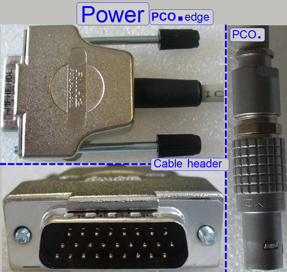
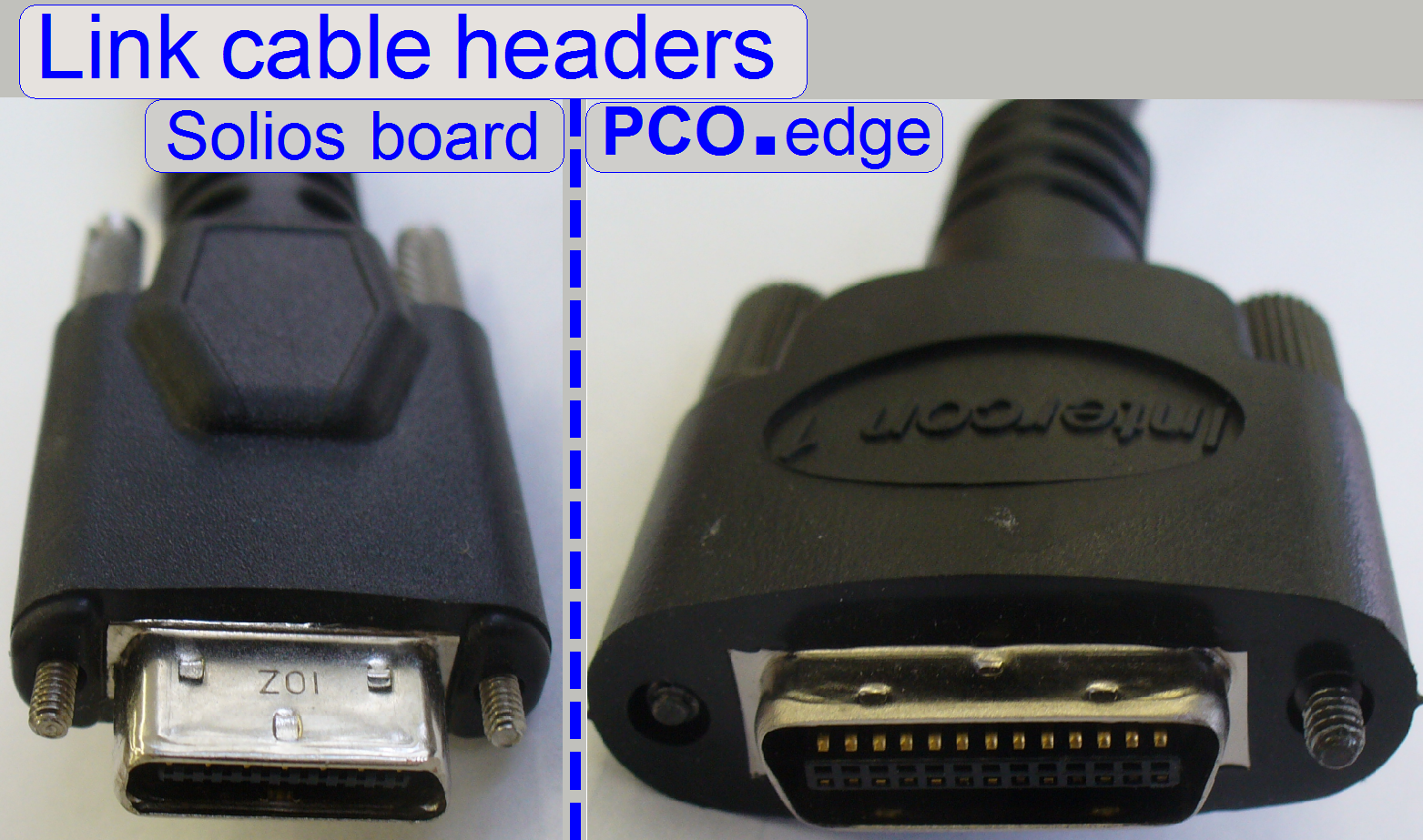
Camera Link connection
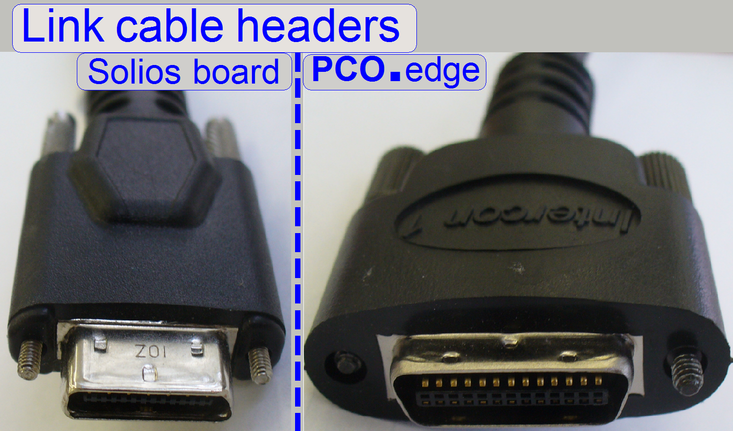 The data transfer between camera
and Solios board is realized with two Camera link
cables.
The data transfer between camera
and Solios board is realized with two Camera link
cables.
Both camera link cables are
from the same type and the headers are wired 1:1.
The cable header on the Solios board side is a “Camera link HDR26” (CL mini) type
connector during on the camera side a “Camera link (CL) original” type cable
header is used.
Important
The Camera link cable, connected to the port “CameraLink
A” of the camera have to be connected to the “Channel
If
these conditions are not met, the camera will not be found or recognized by the
software!
Driver
install
The camera PCO.edge is fully handled by the
scan software “SlideScanner.exe” via the Solios
board(s); therefore, an explicit driver installation procedure is not required.
![]() “Setup the Matrox Imaging Library version 9.0 (MIL 9.0)”
“Setup the Matrox Imaging Library version 9.0 (MIL 9.0)”
Power;
P250
 The camera gets
its power of 12V- DC 15W by default from the “Power
distribution and switch board” of the scanner; in exceptions or special
conditions an external power supply may be used (e.g. SCAN,
The camera gets
its power of 12V- DC 15W by default from the “Power
distribution and switch board” of the scanner; in exceptions or special
conditions an external power supply may be used (e.g. SCAN,
The camera interface is a so called “Hot plug interface” so the cable
header may be removed or plugged during the computer is powered on, but wait
until the data transfer between camera and link board is finished (if in
progress).
Nevertheless, the camera should be powered off before any connection
modifications are done.
Switch off the camera or
unplug the power header or switch off the entire scanner.
Make the desired connections and secure the
header connection with the lock bolts.
Switch on the scanner, the
camera or plug the power header.
Triggering
The trigger output 4 of the camera is used to trigger the Lumencor
SPECTRA light engine.
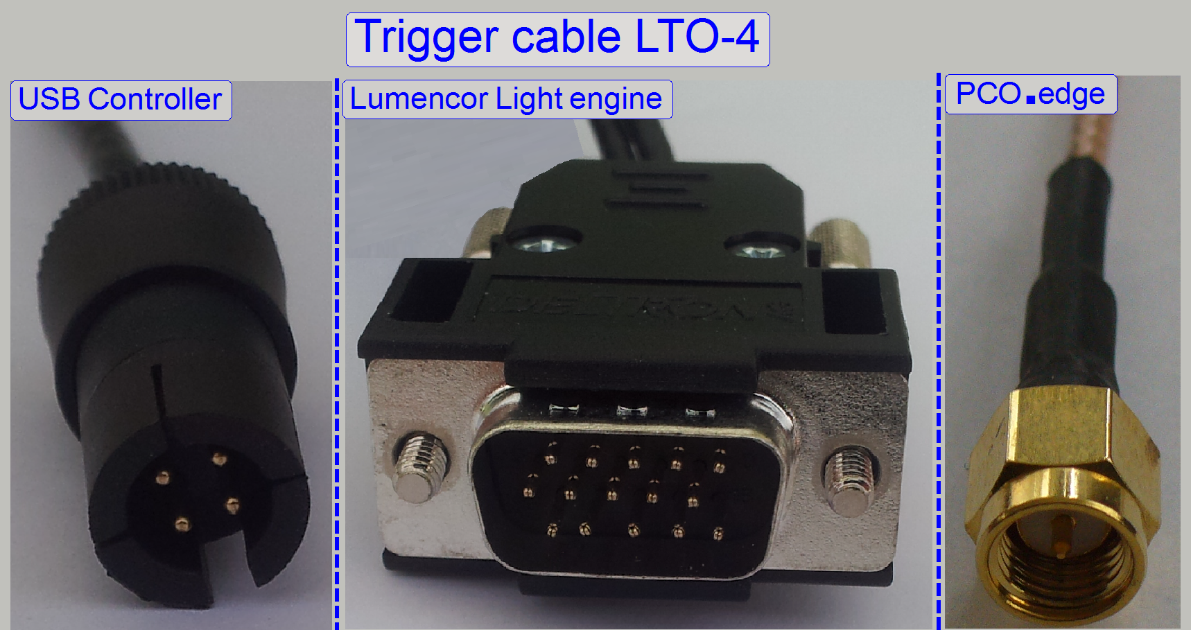
In SCAN_II and MIDI_II type scanners the trigger cable LTO-4 is used.
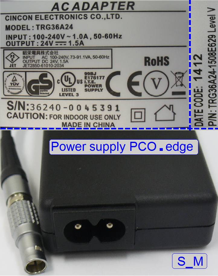 This power supply
is used if the PCO.edge camera works in SCAN or
This power supply
is used if the PCO.edge camera works in SCAN or
PCON
 The principle of
triggering is the same as for the P250 but cable headers are modified!
The principle of
triggering is the same as for the P250 but cable headers are modified!
The trigger output 4 of the camera is used to trigger the Lumencor
SPECTRA light engine and the RGB illumination
unit.
![]() Control,
cables and connections
Control,
cables and connections
Used in: P250, SCAN,
 The pco.edge
2.4M is a camera link interfaced, monochrome camera and is used for scanning of
stained tissues in the fluorescent scan mode. The color (wave length of the
light) is defined by the used filter block, the wavelength of the exciting
light beam and the gray scale image, taken by the pco.edge
camera defines the partial intensity. By using the software coloring method,
images of a very high quality and color fidelity can be produced.
The pco.edge
2.4M is a camera link interfaced, monochrome camera and is used for scanning of
stained tissues in the fluorescent scan mode. The color (wave length of the
light) is defined by the used filter block, the wavelength of the exciting
light beam and the gray scale image, taken by the pco.edge
camera defines the partial intensity. By using the software coloring method,
images of a very high quality and color fidelity can be produced.
Sensor: Scientific CMOS CIS2020A
Resolution: 4.2Mpixels
Pixel array: 2048 (H) x 2048 (V)
Pixel size (h x v): 6.5
µm x 6.5 µm
Transfer rate: 100fps (full size)
![]() Rolling shutter vs. Global
shutter (stored)
Rolling shutter vs. Global
shutter (stored)
Power
requirements
Input: 12 … 24 VDC (+/- 10 %)
Power consumption:
20W max. (typ. 10 W @
![]() “Possible scan modes with different cameras and
magnifications in the software version 1.16; 1.17beta and 1.17
“Possible scan modes with different cameras and
magnifications in the software version 1.16; 1.17beta and 1.17
“Useable
magnifications and resulting resolutions of scan cameras”
Information
about features, precautions and others can be found in the file: “BR_pco_edge42_105_online.pdf”
or further, detailed technical information: “pco_edge_manual_V1-01.pdf”.
Camera Link connection
 The data transfer between camera
and Solios board is realized with two Camera link
cables.
The data transfer between camera
and Solios board is realized with two Camera link
cables.
Both camera link cables are
from the same type and the headers are wired 1:1.
The cable header on the Solios board side is a “Camera link HDR26” (CL mini) type
connector during on the camera side a “Camera link (CL) original” type cable
header is used.
Important
The Camera link cable, connected
to the port “CameraLink A” of the camera have to be
connected to the “Channel
If
these conditions are not met, the camera will not be found or recognized by the
software!
Power;
P250
The camera gets its power of 12V- DC 15W by default from the “Power
distribution and switch board” of the scanner; in exceptions or special
conditions an external power supply may be used (e.g. SCAN,
The camera interface is a so called “Hot plug interface” so the cable
header may be removed or plugged during the computer is powered on, but wait
until the data transfer between camera and link board is finished (if in
progress).
Nevertheless, the camera should be powered off before any connection
modifications are done.
Switch of the
camera or unplug the power header or switch off the entire scanner.
Make the desired connections
and secure the header connection with the lock bolts.
Switch on the scanner, the
camera or plug the power header.
Power;
SCAN and
Triggering
The trigger output 4 of the camera is used to trigger the Lumencor
SPECTRA light engine.
Driver
install
The camera PCO.edge 4.2Mp is fully handled by
the scan software “SlideScanner.exe” via the Solios
board(s); therefore, an explicit driver installation procedure is not required.
![]() “Setup the Matrox Imaging Library version 9.0 (MIL 9.0)” and “Solios
board”
“Setup the Matrox Imaging Library version 9.0 (MIL 9.0)” and “Solios
board”
Used in: P250, SCAN and
 The AxioCam
MRm Rev.3 camera is a 12 bit monochrome camera
especially used for fluorescent scan. The color (wave length of the light) is
defined by the used fluorescent filter and the gray scale image, taken by the AxioCam camera defines the intensity. By using the software
coloring method, images of a very high quality and color fidelity can be
produced.
The AxioCam
MRm Rev.3 camera is a 12 bit monochrome camera
especially used for fluorescent scan. The color (wave length of the light) is
defined by the used fluorescent filter and the gray scale image, taken by the AxioCam camera defines the intensity. By using the software
coloring method, images of a very high quality and color fidelity can be
produced.
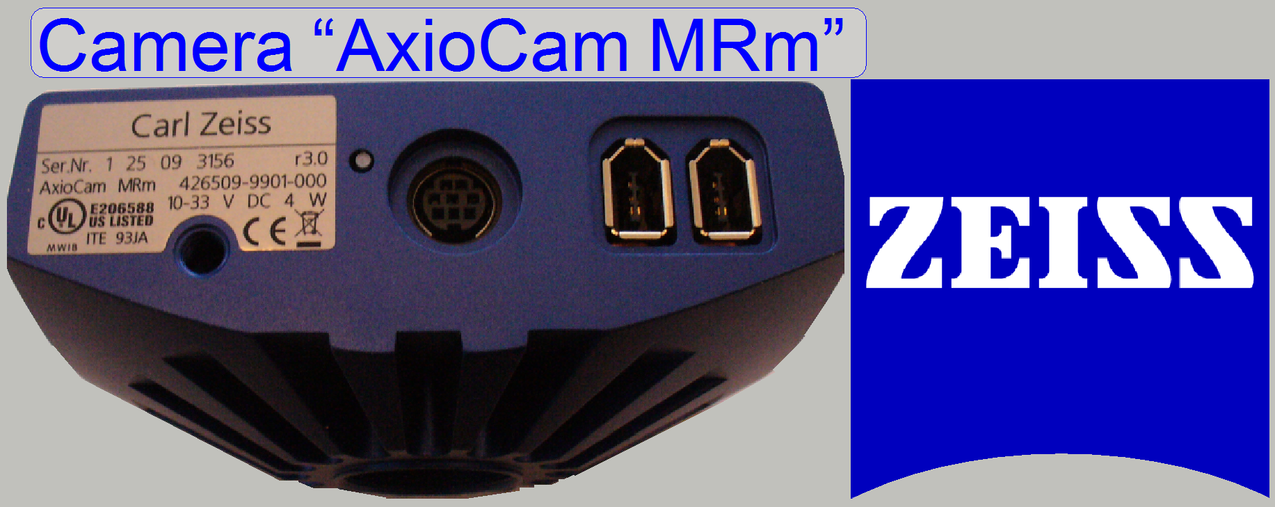
CARL ZEISS Monochrome camera for fluorescent scan
Effective pixels: 1388 x 1040 (1.4 Mega pixels)
Pixel resolution (with 20x objective and C-mount
adapter 1x): 0.33μm
Interface type: IEEE 1394a
More information about features, precautions and others can be found in
the file “AxioCam MRm Rev.3”
![]() “Useable
magnifications and resulting resolutions of scan cameras”
“Useable
magnifications and resulting resolutions of scan cameras”
FireWire IEEE 1394 “a” header type controller (card)
FireWire IEEE
1394 “a” to “a” header type cable
Install and driver CD for Pannoramic scanners, “AxioCam.inf”
Cables
and connections
The camera cable connection is
realized with an IEEE 1394 “a” type header and the
cable is connected to the inserted controller board with a FireWire IEEE 1394 “a” type or “b” screw lock type header.
The camera needs a FireWire port of the
extension card. The camera has a FireWire input port (connected to the
computer) and a link port (connected to the next camera; not used in Pannoramic scanners). If the camera is not recognized after
driver installing, please try with the other port connector of the camera.
![]() “FireWire interface”, “Precautions” and “Connect the camera”
“FireWire interface”, “Precautions” and “Connect the camera”
Driver
install
· Windows®
7x64bit Setup the driver for the
camera “Carl Zeiss AxioCam MRm R3”
· Windows®
XP Setup the XP driver
for the camera “Carl Zeiss AxioCam
MRm R3”
Stingray F-
Used in: SCAN,
![]() The camera uses a single chip CCD and
produces pictures of a good quality, and is used for brightfield
and fluorescent scan likewise. Because the sensitivity of this camera is very
high and the RGB logic contains a hardware equalizer, the color fidelity is
also high.
The camera uses a single chip CCD and
produces pictures of a good quality, and is used for brightfield
and fluorescent scan likewise. Because the sensitivity of this camera is very
high and the RGB logic contains a hardware equalizer, the color fidelity is
also high.
Further information about “Single
chip CCD color capturing” and
‘Single chip CCD” Wikipedia
AVT Stingray color camera Fire
Wire 1/2" type progressive SCAN IT CCD
Video data output: 8/14 bit
Frame rate: ~15 FPS
Effective pixels: 1388 x 1038 (1.44 Megapixels)
Cell size: 4.65 x 4.65μm
Pixel resolution (with 20x objective and C-mount adapter
1x): 0.23μm
Interface type: IEEE 1394b, screw lock
![]() “Useable
magnifications and resulting resolutions of scan cameras”
“Useable
magnifications and resulting resolutions of scan cameras”
“Stingray_DataSheet_F-146_V4.0.1_en.pdf”,
“”
Fire wire IEEE
1394 “b” screw lock type controller board
Fire wire IEEE
1394 “b” screw lock type cable
Install and driver CD for Pannoramic scanners AVT Fire package
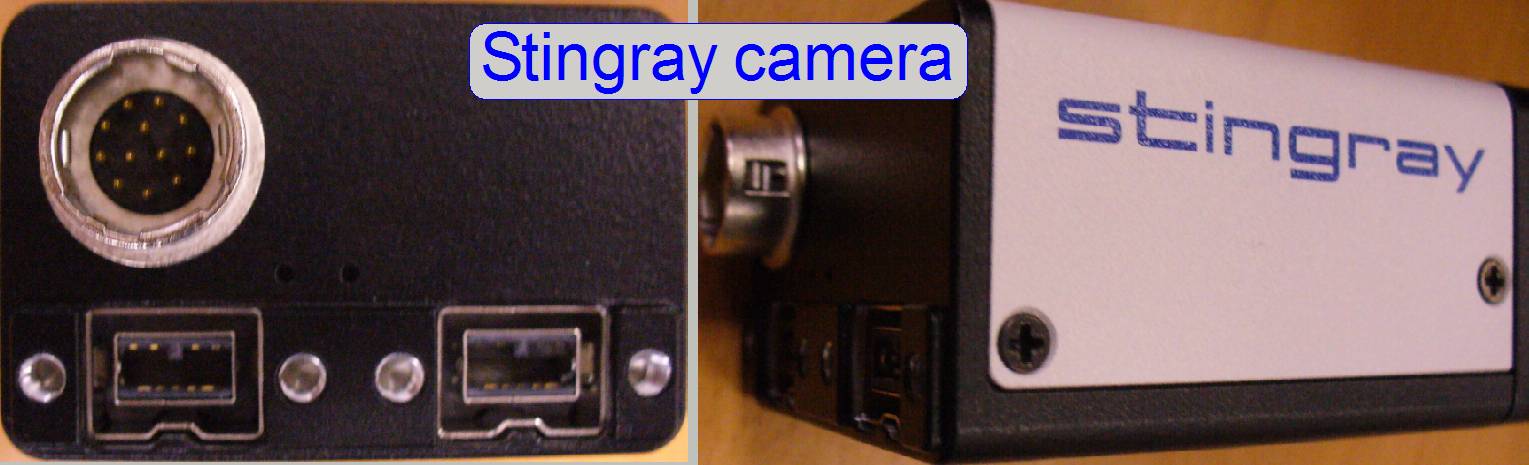
Cables
and connections
The camera cable connection is
realized with an IEEE 1394 “b” screw lock type header
and the cable is connected to the inserted controller board with a FireWire IEEE 1394 “a” type or “b” screw lock type header.
The camera needs a FireWire port of the
extension card. Because the AVT fire package uses the entire controller of the
board, no other type cameras (like the DFK21F04) can be connected to this
controller (card). The camera has a FireWire input port (connected to the
computer) and a link port (connected to the next camera; not used in Pannoramic scanners). If the camera is not recognized after
driver installing, please try with the other port connector of the camera also.
![]() “FireWire interface”, “Precautions” and “Connect the camera”
“FireWire interface”, “Precautions” and “Connect the camera”
Check or set the following entries of the file
“MicroscopeConfiguration.ini” (until SW version 1.14):
[Microscope]
ScanCameraType= AVT Stingray F146C
[ScanCamera]; the following
parameter values are for information only!
Gain=0
Shutter=1000
Gamma=0
Saturation=128
WhiteBalance_U=81
WhiteBalance_V=45
Sharpness=0
Brightness=0
TriggerTimeout=5000
AutoCalibrate=TRUE
Check / set the following entries of the file “MicroscopeSettings.ini”:
[ReflectorTurret]
CameraName = Stingray F146C
Driver
install
· Since
the software version 1.16 Setup_AVT_cam_Driver
Windows® 7x64bit
· Until
the software version 1.14 Setup AVT_XP_FirePackage Windows® XP x 32bit
Marlin F-
Used in: SCAN,
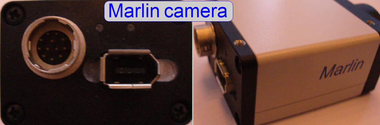 The camera uses a single chip CCD and
produces color pictures of a good quality; it is used for brightfield
and fluorescent scan likewise. Because the sensitivity of this camera is very
high and the RGB logic does not contain a hardware equalizer, the illumination
of the FOV must be adjusted very well, otherwise the color fidelity is reduced.
This is the reason why in newer systems this camera is replaced by the camera
“Stingray F-
The camera uses a single chip CCD and
produces color pictures of a good quality; it is used for brightfield
and fluorescent scan likewise. Because the sensitivity of this camera is very
high and the RGB logic does not contain a hardware equalizer, the illumination
of the FOV must be adjusted very well, otherwise the color fidelity is reduced.
This is the reason why in newer systems this camera is replaced by the camera
“Stingray F-
Data rate: 400 Mbit/s max.
Speed: 17 fps max.
Interface type: IEEE 1394a
![]() “Useable
magnifications and resulting resolutions of scan cameras”
“Useable
magnifications and resulting resolutions of scan cameras”
“Marlin_DataSheet_F-146_V4.0.0_en.pdf” and ”Single chip CCD color capturing”
Fire wire IEEE
1394 “a” type controller card
Fire wire IEEE
1394 “a” type cable
Install and driver CD for Pannoramic scanners; AVT Fire package
Cables
and connections
The camera is connected to the
inserted controller board with a FireWire IEEE 1394
“a” type cable. The camera needs a FireWire
port of the extension card. Because the AVT fire package uses the entire controller
of the board, no other type cameras (like the DFK 21F04) can be connected to
this controller.
![]() “FireWire interface”, “Precautions” and “Connect the camera”
“FireWire interface”, “Precautions” and “Connect the camera”
Driver
install
· Since
the software version 1.16 Setup_AVT_cam_Driver
Windows® 7x64bit
· Until
the software version 1.14 Setup AVT_XP_FirePackage Windows® XP x 32bit
Used in: SCAN,
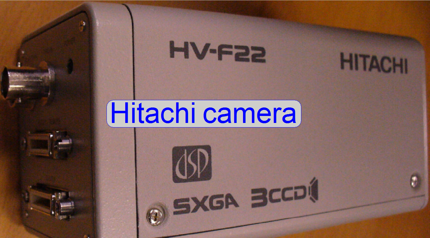 The camera contains for the colors red green and
blue a separate CCD; it is a “Three CCD camera”.
Each CCD uses a 10 bit A/D converter so the color fidelity is very high.
Because the camera uses an own interface board and own interface cables
(Data-Link interface), the transfer rate is very high as well. Primarily the
camera is advised for brightfield scan procedures but
there can be produced fluorescent scans with a high quality as well.
The camera contains for the colors red green and
blue a separate CCD; it is a “Three CCD camera”.
Each CCD uses a 10 bit A/D converter so the color fidelity is very high.
Because the camera uses an own interface board and own interface cables
(Data-Link interface), the transfer rate is very high as well. Primarily the
camera is advised for brightfield scan procedures but
there can be produced fluorescent scans with a high quality as well.
Hitachi HV-F22CL 3CCD progressive
scan color camera
Video Data output: 3 x 10 bit
Frame rate: ~15 FPS
Effective pixels: 1360 x 1024 (1.4 Megapixels)
Pixel resolution (with 20x objective and C-mount
adapter 1x): 0.23 μm
![]() “Useable
magnifications and resulting resolutions of scan cameras”
“Useable
magnifications and resulting resolutions of scan cameras”
"Brochure", “HV-F22CL Specifications”,
“Operation Manual”, Technical information”
(stored)
Hitachi
HV-F22CL Home page
Requirements
 The Matrox Solios XCL controller board; delivered
with the camera
The Matrox Solios XCL controller board; delivered
with the camera
Interface cables;
delivered with the camera
Power supply; delivered with the camera
Matrox Imaging Library MIL 8.0 or MIL 9.0; to
install the hardware
Cables
and connections
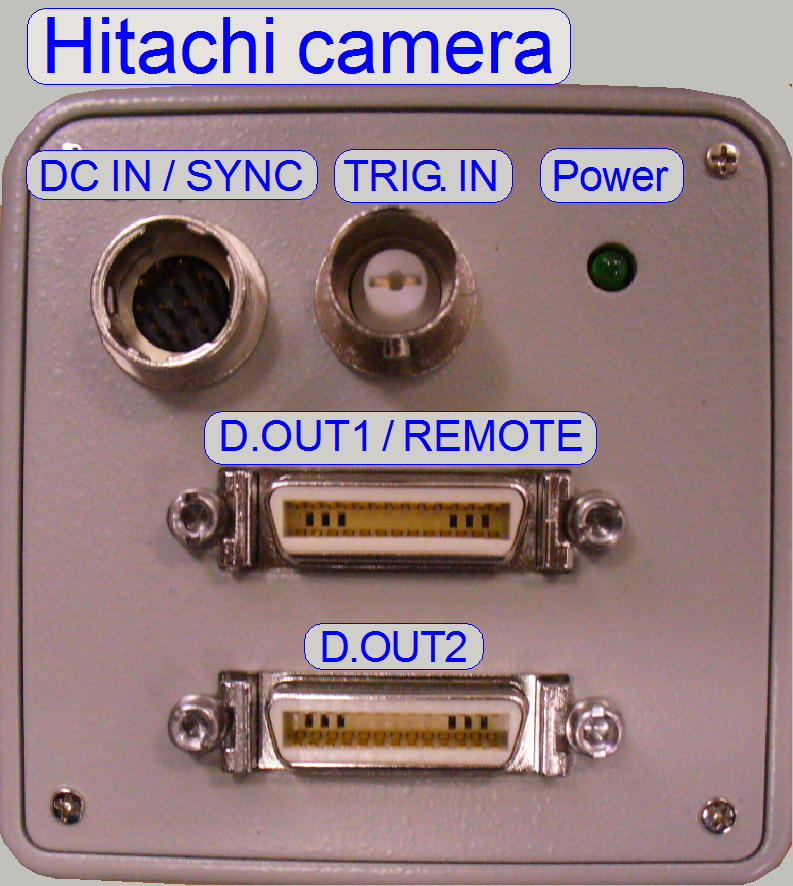 The Matrox Solios XCL controller
board should be inserted into a PCI slot with 64bit /66MHz
or higher (in software versions until 1.14)!. The camera is
connected to the computer with the D.OUT1 and D.OUT2 data link cables to the
appropriate connectors of the Solios board. The
delivered power supply is connected to the DCIN / SYNC input of the camera.
The Matrox Solios XCL controller
board should be inserted into a PCI slot with 64bit /66MHz
or higher (in software versions until 1.14)!. The camera is
connected to the computer with the D.OUT1 and D.OUT2 data link cables to the
appropriate connectors of the Solios board. The
delivered power supply is connected to the DCIN / SYNC input of the camera.
The installation
of the board and the driver installation procedures are suggested to be done by
a qualified system administrator.
Important
The Solios board should be inserted into a slot PCI-E
generation 1 (PCI-Express x8 gen.1); otherwise, if a PCI-E generation 2 slot is
used, the system may freeze during boot (in software versions until 1.14)!
Detailed information about hardware install and software setup procedures
can be found on the Install CD for Pannoramic
scanners in the files:
<CD ROM>:Drivers\Matrox Imaging Library\
Matrox Imaging Library Installation Guide MIL
8.0 or MIL9.0
respectively
And
<CD ROM>:Drivers\Matrox Imaging
Library\Hitachi HV-F22CL (Original CD)\Doc\ English \Operation_Manual
Check or set the following entries of the file
“MicroscopeConfiguration.ini” (until SW version 1.14):
[Microscope]
ScanCameraType=Hitachi_HV_F22CL
[ScanCamera]; until
SW version 1.14; the following parameter values are for information only!
Gain=0
Shutter=1000
Gamma=0
Saturation=128
WhiteBalance_U=86
WhiteBalance_V=44
Sharpness=0
Brightness=0
TriggerTimeout=5000
AutoCalibrate=TRUE
Check or set the following entries of the file “MicroscopeSettings.ini”:
[ReflectorTurret]
CameraName =
Hitachi_HV_F22CL
To
install the camera driver for the camera Hitachi HV-F22CL
Please refer to the file:
<CD ROM>\Drivers\Matrox Imaging Library\
Matrox Imaging Library Installation Guide.doc
Used in: MIRAX SCAN and MIRAX
DESK
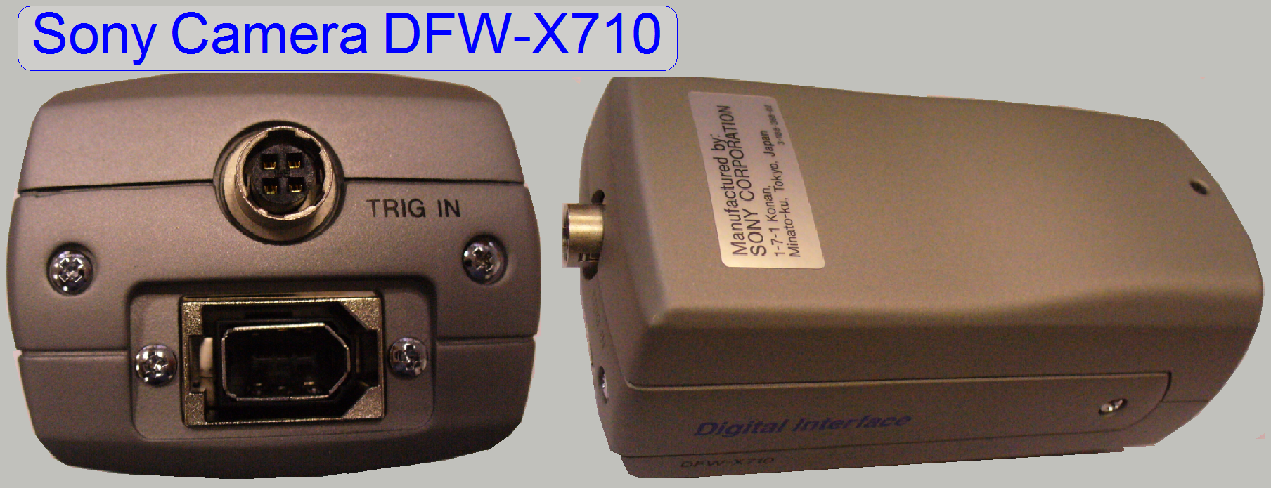 The Sony camera uses a single chip CCD and
was used in early SCAN,
The Sony camera uses a single chip CCD and
was used in early SCAN,
Frame rate: 15 fps max.
Cell size: 4.65 x
4.65μm
Transfer speed: 400/200 Mbps
(400 with external triggering)
![]() “Useable
magnifications and resulting resolutions of scan cameras”
“Useable
magnifications and resulting resolutions of scan cameras”
Manuals: DFW_SX910_X710_s, dfw-sx910-x710_data
Further information can be found in the
chapter “Sony_DFW_X710_cam_and_driver”
Lumencor SPECTRA light engine®
 The Lumencor SPECTRA Light Engine® is a light source, used to
illuminate the field of view of fluorescent stained tissues; the required light
wavelengths are created by light modules. The light modules are switched on or
off separately, as required for the excitation wavelength to be used.
The Lumencor SPECTRA Light Engine® is a light source, used to
illuminate the field of view of fluorescent stained tissues; the required light
wavelengths are created by light modules. The light modules are switched on or
off separately, as required for the excitation wavelength to be used.
·
The Lumencor SPECTRA Light
Engine® is delivered together with the PCO.edge FL
scan camera.
·
The following chapter is true for the
PSCAN and the PMIDI also.
·
 The use of a
separate light module for each excitation wavelength allows the precise
creation of the required light wavelength.
The use of a
separate light module for each excitation wavelength allows the precise
creation of the required light wavelength.
·
The light sources are switched separately and
electronically, software controlled.
·
The exchange of the excitation wavelength is done very
quickly.
·
The use of multiple band filters is possible.
·
Minimizing of mechanical movements (of the filter
wheel) saves scan time.
·
Bleaching of the fluorescent tissue is minimized,
because the exciting light is switched on only during the shutter time of the
camera (hardware triggering).
·
Low heat emission.
·
Low power consumption.
·
The scan process of the virtual tissue in the
fluorescent scan mode speeds up.

·
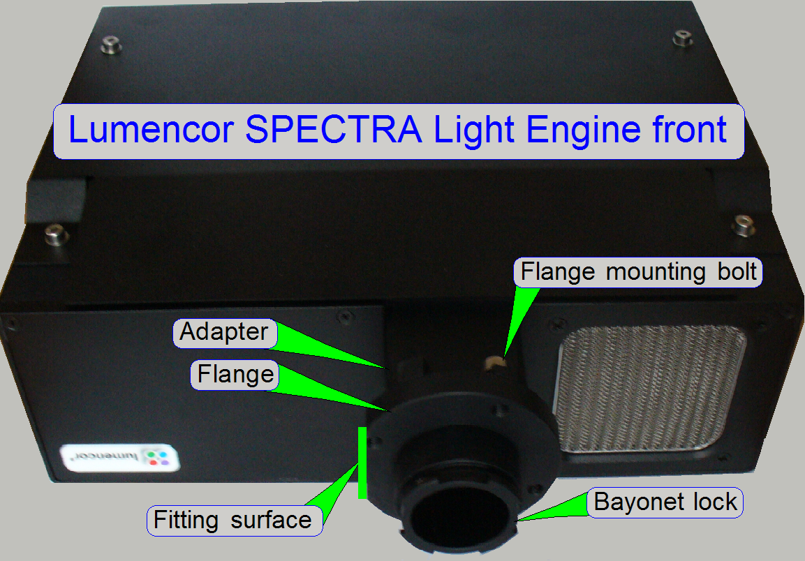
 The Lumencor SPECTRA Light Engine® (shown in its working
position; upside down)
The Lumencor SPECTRA Light Engine® (shown in its working
position; upside down)
·
The adapter; with heat barrier filter and concentrator
lens
·
The flange with bayonet lock mechanism (the Lumencor light source adapter)
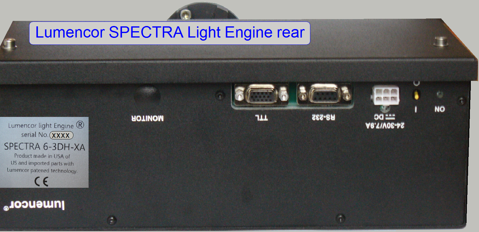
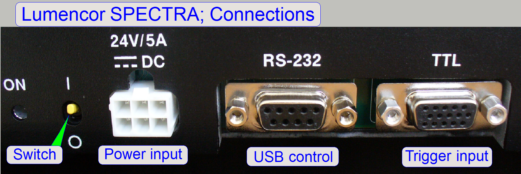
On
the rear
Power connector, power switch
and power LED
 Control input of the light
engine (RS-232)
Control input of the light
engine (RS-232)
Detailed information
about features, precautions, warnings and technical data can be found in the
file “Lumencor_Spectra_LE_User_Manual.pdf”
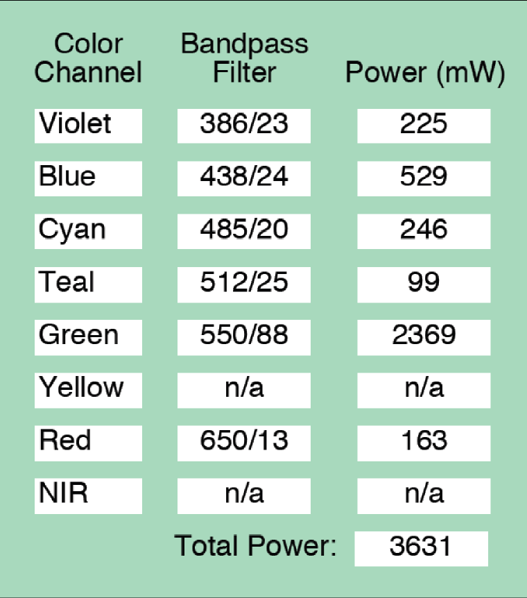 The light modules in the lumencor
SPECTRA light engine, delivered by 3DHISTECH, creating the excitation lights
with the wavelengths as shown on the right.
The light modules in the lumencor
SPECTRA light engine, delivered by 3DHISTECH, creating the excitation lights
with the wavelengths as shown on the right.
To excite the fluorophore of the tissue, the
light wavelength, selected in the Lumencor SPECTRA,
the characteristic of the quad band filter (or the single band filter) and the
exciting wavelength of the fluorophore must meet each
other, otherwise, the fluorophore will not be
excited, the exposure time rise up and the quality of the scanned tissue
becomes bad.
Light
Engine Subsystem
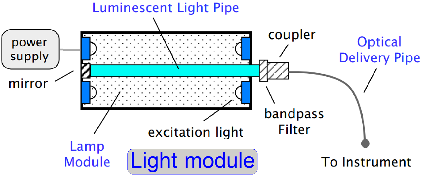 Each light engine
consists of a lamp and delivery optics. The lamp subsystem embodies multiple
modules optimized to each produce a precise set of wavelengths. One such module
is shown on the right. Here Lumencor’s light pipe
technology is the source. Light is generated by a luminescent light pipe which
is driven by an e-beam, LEDs or UV lamps. The pipe,
which may consist of any of a variety of luminescent materials (e.g. rare earth
doped glass, organic doped plastic, single crystal fiber)
is tailored to emit light in the UV through the NIR. In the case of the rare
earths, emission is inherently narrow due to their atomic-like energy
structure. Any unwanted light is removed by a simple bandpass
filter. The light output from the pipe is fed into an optical delivery pipe and
into the instrument. The fast luminescence decay results in rapid switching
with no appreciable warm up time.
Each light engine
consists of a lamp and delivery optics. The lamp subsystem embodies multiple
modules optimized to each produce a precise set of wavelengths. One such module
is shown on the right. Here Lumencor’s light pipe
technology is the source. Light is generated by a luminescent light pipe which
is driven by an e-beam, LEDs or UV lamps. The pipe,
which may consist of any of a variety of luminescent materials (e.g. rare earth
doped glass, organic doped plastic, single crystal fiber)
is tailored to emit light in the UV through the NIR. In the case of the rare
earths, emission is inherently narrow due to their atomic-like energy
structure. Any unwanted light is removed by a simple bandpass
filter. The light output from the pipe is fed into an optical delivery pipe and
into the instrument. The fast luminescence decay results in rapid switching
with no appreciable warm up time.
The light pipe geometry integrates a significant fraction of the light
leading to high external efficiencies.
These efficiencies are optimized by the innovative design of the lamp
module including the excitation source and the unique geometric shape of the
pipe. Increased power levels, exceeding those typical for lasers in these
applications, can readily be obtained by scaling the light pipe and associated
excitation.
Source: Lumencor-White-Paper.pdf
(stored)
Watch slide show: Lumencor SPECTRA
light engine
· The Lumencor SPECTRA creates the excitation light by using
light modules; each module creates the light in the specified wavelength and
the excitation beams are routed by the use of dichroic
mirrors.
The modules are switched on
or off separately, controlled by the scan program via the control input of the
light engine, so the required light wavelength to excite the appropriate fluorophore of the tissue can be created and selected.
Dichroic mirror
A dichroic mirror reflects the lower
wavelength of the light while the higher wavelength passes thru it. The edge
wavelength keeps the border between lower wavelengths and higher wavelengths.
![]() Dichroic beam splitter (Semrock)
Dichroic beam splitter (Semrock)
P250
 The lumencor SPECTRA get its power of 24V- 5A DC from the
internal power supply tdk-Lambda of the scanner P250.
The lumencor SPECTRA get its power of 24V- 5A DC from the
internal power supply tdk-Lambda of the scanner P250.
Because the relays of the power distribution and switch board can not
handle the required current of 5A DC, a Power amplifier is
used; it is situated in the common housing of the power supply and the switch
board.
![]() The real working position of
the Lumencor SPECTRA Light Engine® is upside down!
The real working position of
the Lumencor SPECTRA Light Engine® is upside down!
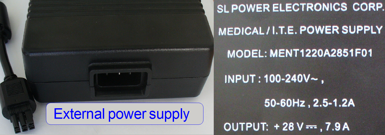 If the Lumencor SPECTRA Light Engine is used together with the
PSCAN or the PMIDI, the shown external power supply is used.
If the Lumencor SPECTRA Light Engine is used together with the
PSCAN or the PMIDI, the shown external power supply is used.
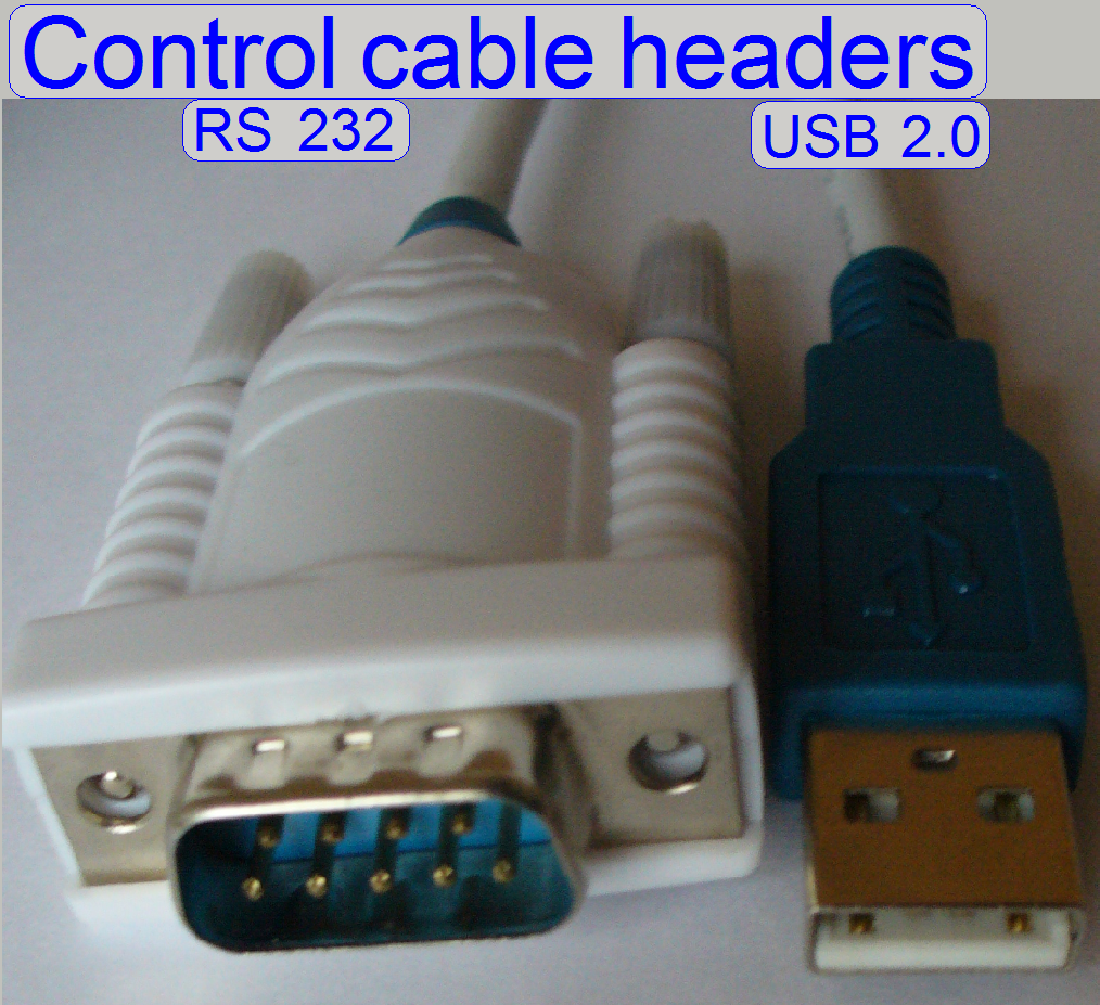
The control of the light engine is realized via the RS-232 input; on the
other end of the cable an USB 2.0 A-type header is connected.
The control and selecting of the appropriate light wavelength is
realized via an USB-port.
The cable header RS-232
contains the converter logic to convert the interfaces from USB2.0 to RS-232
and vice versa.
· If the control cable was
exchanged or another USB 2.0 port (on the computer) is used, the USB port
address has to be checked and probably updated.
![]() Check and
update the USB port address.
Check and
update the USB port address.
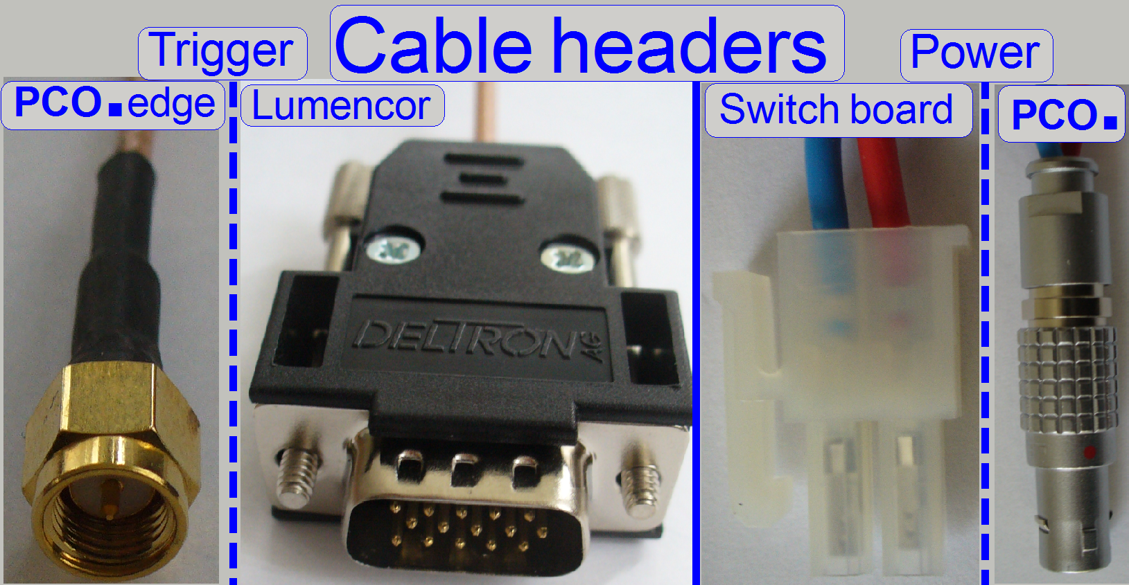
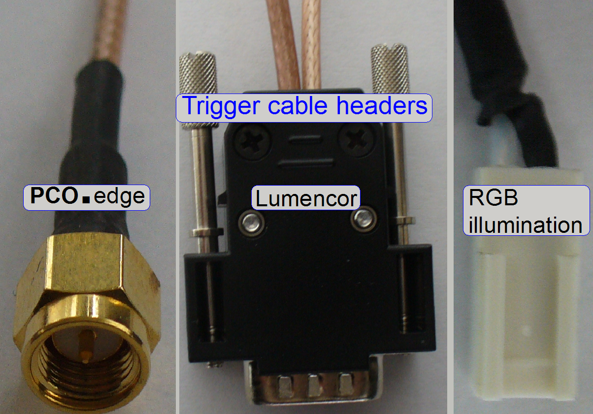 The trigger cable
is connected to the TTL port of the lumencor SPECTRA.
The trigger cable
is connected to the TTL port of the lumencor SPECTRA.
If the shutter of the PCO camera is open, the selected light module
(selected via the USB port) will be switched on.
Remark
The extension to the RGB BF illumination unit is used in the PCON only!
 The principle of
triggering is the same as for the P250 but cable headers are modified!
The principle of
triggering is the same as for the P250 but cable headers are modified!
The trigger output 4 of the camera is used to trigger the RGB
illumination unit also.
![]() Control, cables and connections
Control, cables and connections
Check and update
the USB port address
 Because the
control of the light engine is done via an USB 2.0 port of the computer, the
scan software has to know the port address.
Because the
control of the light engine is done via an USB 2.0 port of the computer, the
scan software has to know the port address.
The port address is defined in the section [Lumencor]
of the file “MicroscopeConfiguration.ini”.
If the control cable was
exchanged or another USB 2.0 port (on the computer) is used, the USB port
address has to be checked and updated.
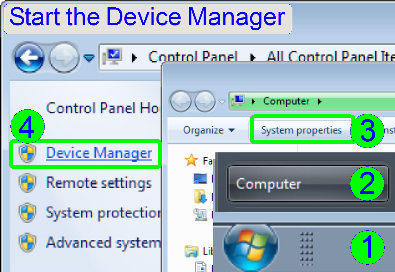
Start
the “Device manager”
· Press “Start”(1), “Computer”(2), “System properties”(3),and “Device
Manager”(4).
Find
the USB control port address
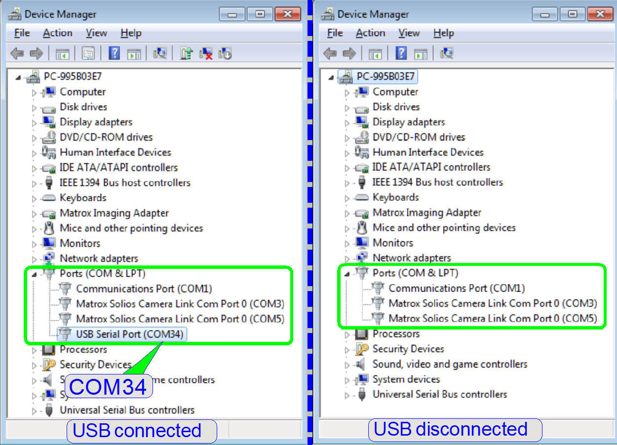
By connecting or disconnecting the USB connector, the state of the item “USB
serial port (COMxx)” is changed.
It is shown in the section “Ports (COM & LPT)” of the device
manager; in this example the COM port address 34 is found.
Update the
section [Lumencor] of the file
MicroscopeConfiguration.ini with the found address:
C:\ProgramData\3DHISTECH\SlideScanner\MicroscopeConfiguration.ini
If the section [Lumencor] does not exist in the file
MicroscopeConfiguration.ini (e.g. the Lumencor SPECTRA
light engine is implemented later or implemented as a result of upgrade) please
create this section.
 If the section [Lumencor] is missed
Please implement the following two lines at the end of
the file “MicroscopeConfiguration.ini” with a text editor, like “Notepad”:
[Lumencor]
COMportNr=xx
Save the file “MicroscopeConfiguration.ini”
without any formatting information, as a *.txt-type file (text only)!
C:\ProgramData\3DHISTECH\SlideScanner\LumencorTable.csv
The lumencor table is used in the software
version 1.15 only to assign exciting light wavelengths to the logical and
physical filter positions. The logical filter position means a color channel
while the physical filter position defines the position of the filter in the
filter wheel of the turret unit.
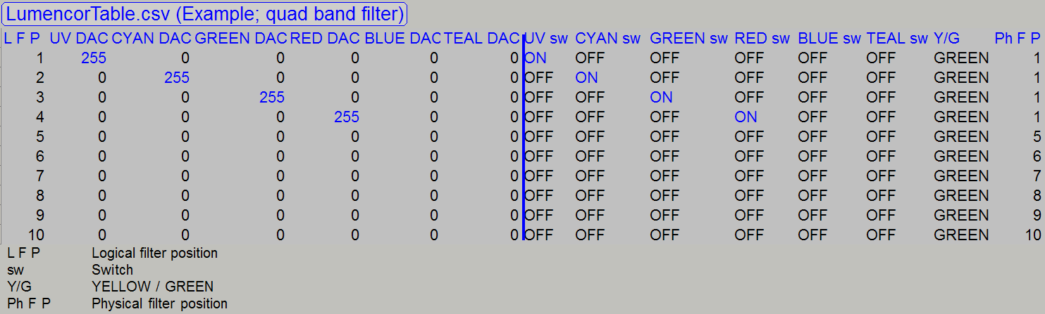
In the example,
only 1 filter block is inserted in the filter wheel position 1.
If a quad band
filter is inserted (as shown), it has four color channels; therefore, the
logical filter positions from 1 to 4 are used.
In this
construction, each color channel occupies a physical filter position also, but
the filter wheel stays always in the position 1; so the filter wheel will not
move.
The next filter
block may be inserted in the filter position 5 of the filter wheel, if
required.
Important
·
If modifications are done in the file “LumencorTable.csv” the file content has to be saved as
txt-type file, without formatting information!
Setup sequence
of the Lumencor SPECTRA
![]() Mount the lumencor
SPECTRA light engine (see also the Lumencor light source adapter).
Mount the lumencor
SPECTRA light engine (see also the Lumencor light source adapter).
Connect the cables
(Trigger, RS-232 and power) and switch on the light engine.
Check and update the USB 2.0 port address
For technicians, sales managers and users
In this chapter, the settings are shown for a quad
band filter and the software version 1.16 or higher.


·
This chapter is true for P250, SCAN and
Start the scan program SlideScanner.exe
In the selector
menu, open the option “Microscope Settings”.
The wavelengths
of the filter are shown on the label.
DA= DAPI; FI= FITC;
TR= TRITC and CY5 = CY5.
For
filter sets, filter blocks and filter characteristics, see also: (Links refer to P250)
![]() “Filter block”, “Introduction
to fluorescent filters”, “Filter
block assembling”, “Cleaning optical
filters” (Semrock), “Staining”, “Virtual tissue” and “Fluorescence
microscopy”.
“Filter block”, “Introduction
to fluorescent filters”, “Filter
block assembling”, “Cleaning optical
filters” (Semrock), “Staining”, “Virtual tissue” and “Fluorescence
microscopy”.
“Matching
Fluorescent Probes with Nikon Fluorescence Filter Blocks”; interactive
Assign colors, color channels,
and filter positions
In
the software version 1.15
Because the quad band filter allows the use of 4 colors
(color channels) in one physical filter position, the next 3 filter positions,
until position 4 can not be equipped with a filter; they are empty positions.
In other words, one quad band filter occupies 4 physical positions of the
filter wheel.
The next filter block can be inserted in the position
5.
See also: Lumencor
table
In
the software version 1.16 or higher
 The quad
band filter allows the use of 4 colors in one physical filter position, but in
opposite to the software version 1.15 every physical filter position may be
equipped with a filter.
The quad
band filter allows the use of 4 colors in one physical filter position, but in
opposite to the software version 1.15 every physical filter position may be
equipped with a filter.
You can insert
multiple band filters and single band filters likewise into the filter wheel,
so theoretically more 10 color channels are be possible, but the software
handles only nine color channels in 1 session.
If other colors
are required, then these can be defined and selected; see also the item (21).
Remark
· The Lumencor
SPECTRA light engine® is
able to create 6 exciting wavelengths so maximal 6 color channels can be
created this time; the use of multiple band filters is possible and
recommended.
· By using
traditional light sources like X-Cite®
Series 120 or equivalent types (white light is created), 9 or more light
channels are possible; but only single band filters are used.
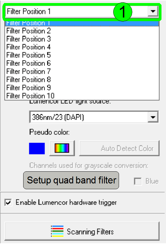
Example
Define the Quad band filter in the “Position
Select the “Position
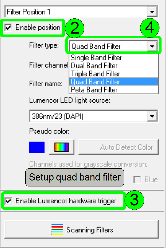
Check the checkbox “Enable position” (2)
Check the checkbox “Enable Lumencor
hardware trigger” (3)
In the P250 and
the use of the PCO.edge camera, this checkbox should
be checked.
If a fluorescent
camera is used in the scanner that is unable to deliver a trigger pulse for the
Lumencor SPECTRA Light Engine, this checkbox should
be unchecked; the selected wavelength will light continuously until the color
will be changed.
Select the Filter type “Quad band filter” (4)
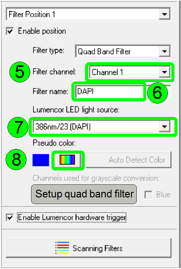
Select channel 1; (5)
Type in the filter name “DAPI” (6)
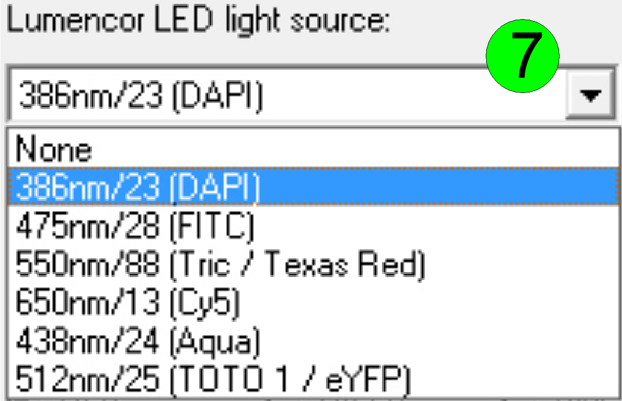
Select the assigned exciting wavelength; (7)
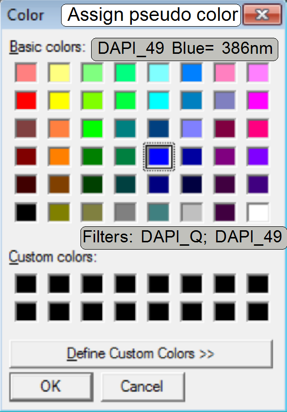
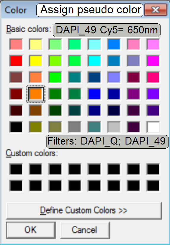
Assign the color to the wavelength; (8)
The here assigned
color will affect the color, seen in the Pannoramic
viewer.
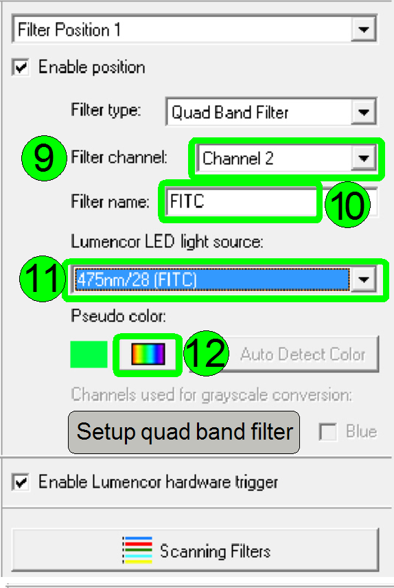
Select channel 2; (9)
Type in the filter name “FITC” (10)
Select the assigned wavelength; (11)
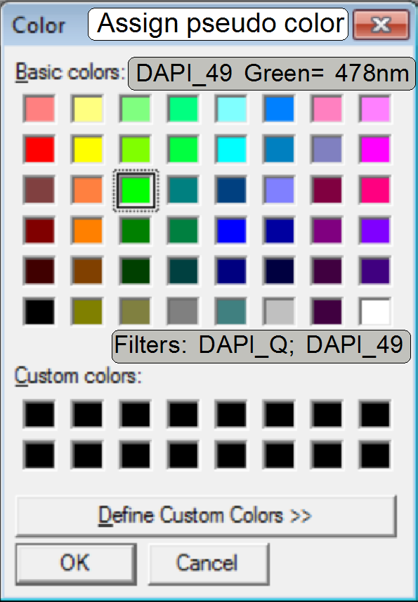
Assign the color to the wavelength; (12)
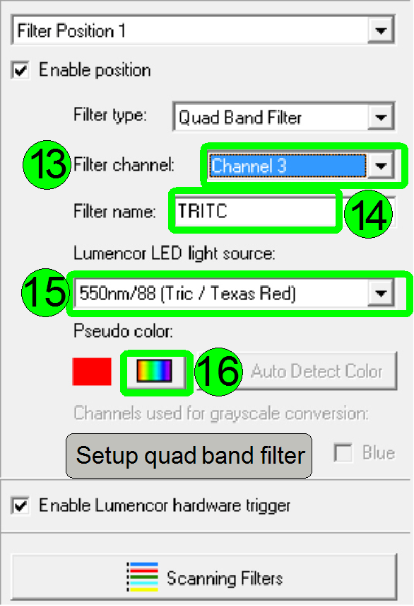
Select channel 3; (13)
Type in the filter name “TRITC” (14)
Select the assigned wavelength; (15)
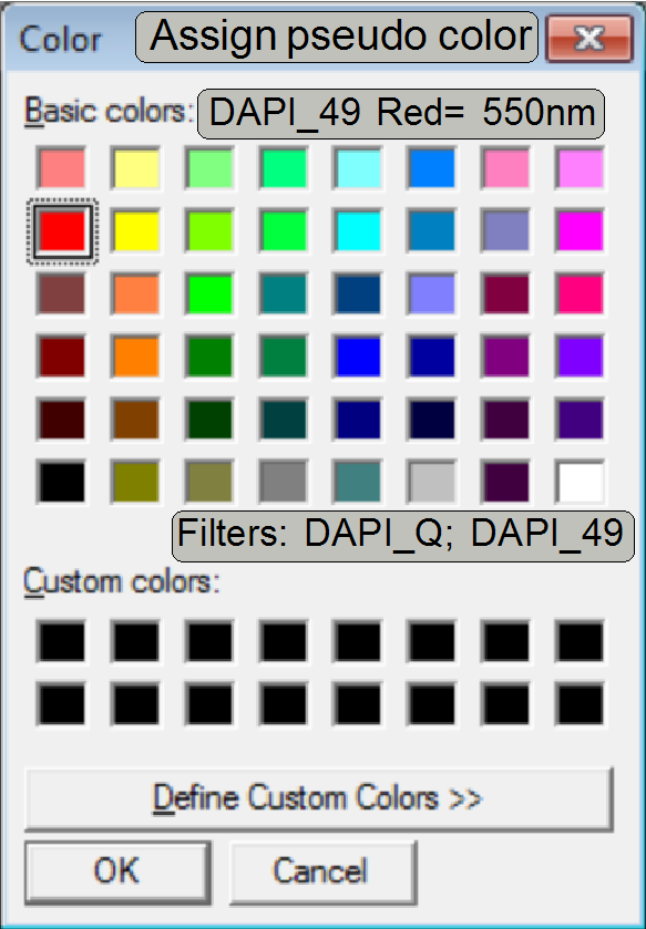
Assign the color to the wavelength; (16)
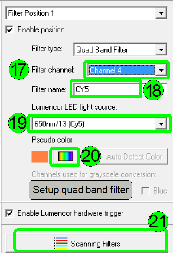
Select channel 4; (17)
Type in the filter name “CY5” (18)
Select the assigned wavelength; (19)
Assign the color to the wavelength; (20)
Press “Scanning Filters” and check; (21).
Check
the assigned positions and color channels (21).
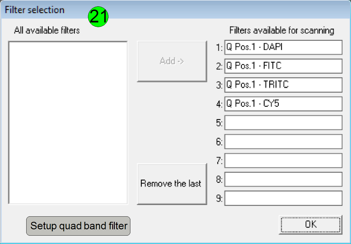 Here,
the defined colors can be arranged for the actual scan session
Here,
the defined colors can be arranged for the actual scan session
If all settings are correct, the quad band filter setup
is finished; now the next filter may be inserted and defined or the fluorescent
scan procedure may be started; see also the user’s manual “Pannoramic_250_FLASH_1.16_User's_Guide_EN_Rev1.pdf”;
page 77ff; “4.5 Using
Fluorescent Manual Mode”.
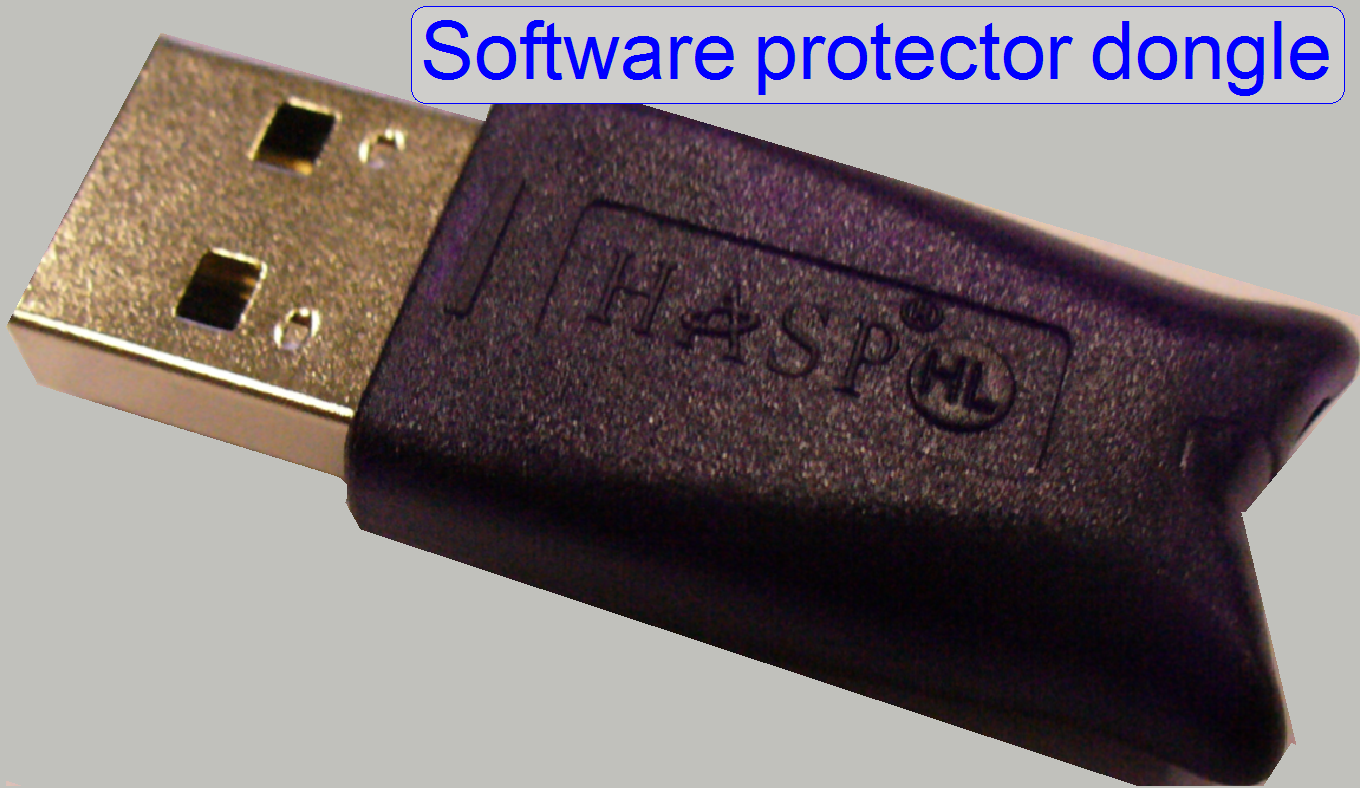
The dongle is a hardware unit, connected to any specified port of the computer
to protect software against unauthorized use. It contains mostly a programmable
logic array or a flash memory area with a protecting data pattern. This data
pattern is compared with the pattern in the software and often analyzed by a
mathematical algorithm or function also. If the result does not produce an
error, the software is ready for use, otherwise the software will not start and
an error message occurs or dongle protected parts of the software can not be
used.
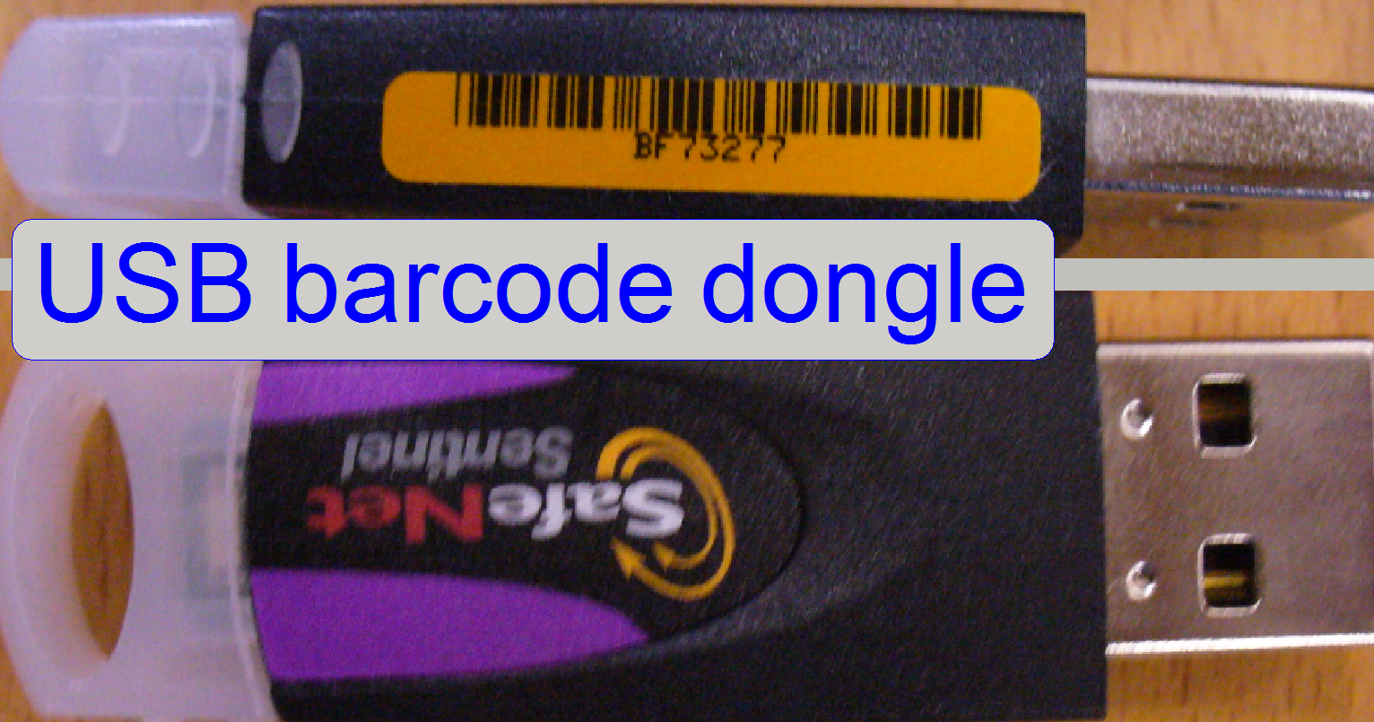 The Matrox USB barcode dongle is used for barcode reading and
protects the option “Barcode reading” of the Matrox
Imaging Library against unauthorized use.
The Matrox USB barcode dongle is used for barcode reading and
protects the option “Barcode reading” of the Matrox
Imaging Library against unauthorized use.
Furthermore, a flag in the Pannoramic scanner
or viewer dongle is used to allow the barcode reading feature of the program
“Slide Scanner”.
If the barcode dongle is missed or not recognized, the message “Barcode dongle not found” will be issued.
If the license for barcode reading is not valid, the message “Barcode reading not licensed” will
be issued.
·
In the Pannoramic DESK, barcode reading is an option and has to be
declared explicitly during ordering the system. If barcode reading is not
allowed in the Pannoramic scanner or viewer dongle,
barcode reading will not work; nevertheless, the barcode dongle is connected.
Further information can be
found in the chapter “Setup
the Matrox Imaging Library version 9.0 (MIL 9.0)”
For software versions with the operating system Windows XP please refer
also to “Setup xP Barcode dongle”
Dongles for Pannoramic
scanners
Important
 Install
and setup the Pannoramic scan, Pannoramic
viewer and Pannoramic server software without
connected dongle! If the dongle(s) are connected after installation of the
software, these should not be disconnected until the next installation procedure
is done.
Install
and setup the Pannoramic scan, Pannoramic
viewer and Pannoramic server software without
connected dongle! If the dongle(s) are connected after installation of the
software, these should not be disconnected until the next installation procedure
is done.
Newer software versions are
able to accept older dongle protections in the same way, as used for the older
software versions.
Until software version 1.8
To protect the Pannoramic scanner (MIRAX)
configuration, the Pannoramic (MIRAX) scan and the Pannoramic (MIRAX) viewer software, two additional, USB
dongles are required. The Pannoramic viewer basic
software is not dongle protected.
Scanner software
dongle
 Requirements
Dongle for the Pannoramic
scanner configuration and software protection or License file
Dongle protected scanner parts and options
Installed scan camera
Extended focus
Fluorescent scan
AVTMarlinF146C
Since software version 1.9
To protect the Pannoramic scanner
configuration, the Pannoramic scan and the Pannoramic viewer software since Software version 1.11 only
one USB dongle is required. The Pannoramic viewer
basic software is not dongle protected. Furthermore, if dongle protected parts
of the Pannoramic viewer are ordered, an additional
dongle will be delivered.
Dongle protected parts
·
Barcode reading enabled
·
The installed scan camera(s)
·
Extended focus
·
Fluorescent scan
The AVTMarlinF146C; since SW version 1.10
supported as ICC1 also
The Zeiss
ICC1 camera; since SW
version 1.10 supported
The AVTStingrayF146C; since SW version 1.12 supported, the same flag as the marlin camera
The AVTPikeF421C; not delivered to user
The AxioCam_MRm_Rev3; supported since SW version 1.10
The Hitachi_HV_F22CL; supported since SW version 1.11
3DHISTECH
Dongle Licensing Manual 2015
Viewer software dongle
Requirements
Dongle for the Pannoramic
Viewer software protection or License file
 Dongle protected viewer
parts and options
Dongle protected viewer
parts and options
3D
OnlineTeleconsultation; since SW version 1.11 this item is
freeware
BookmarkExport
 Dongle protected viewer
parts and options
Dongle protected viewer
parts and options
3D
OnlineTeleconsultation; since SW version 1.11 this item is freeware
·
TMA
·
FLViewer supported since SW version
1.10; since 1.11 this item is freeware
BookmarkExport supported since SW version
1.10
IHLab supported
since SW version 1.11; until version 1.14; the new name is “TumorBoard”
·
HistoQuant supported since SW version 1.11
·
DataVisualisation supported since SW version 1.11
·
MarkerCounter supported since SW version 1.11
·
CytoFISHQuant supported since SW version 1.12
NuclearQuant supported since SW version
1.12
MembraneQuant supported since SW version 1.12
TumorBoard
Relevant description of the
module can be found in User's
guide
The most recent description of the licensed module can be found
on the scan computer.
The path is:
C:\Program Files
(x86)\3DHISTECH\Viewer\Users Guides\*.*