Optics, illumination; P250
For technicians and partly for sales managers!
 This chapter
handles the components of the brightfield illumination and the brightfield optical
path for the scanner Pannoramic 250. Because our products are developed
continuously, some items in the shown menus may differ to the actual software
version you are using; the description is based on the software version 1.15.
This chapter
handles the components of the brightfield illumination and the brightfield optical
path for the scanner Pannoramic 250. Because our products are developed
continuously, some items in the shown menus may differ to the actual software
version you are using; the description is based on the software version 1.15.
To help resolve problems with the illumination and optics, a hardware
description of implemented components and adjustment procedures are added.
Contents
Reduce the
chromatic aberration
To adjust the
camera rotation angle
Check
the optical path adjustments

The optical path includes the following components:
- Pulsed xenon
flash light source
- ND-filter unit
- Collimator
lens with holder
- Condenser
- Objective
- Turret unit or turret plate
- Camera changer
unit, or 90° camera
tube
- Camera adapter
- Brightfield scan
camera
- Fluorescent
scan camera
Brightfield illuminated
optical path
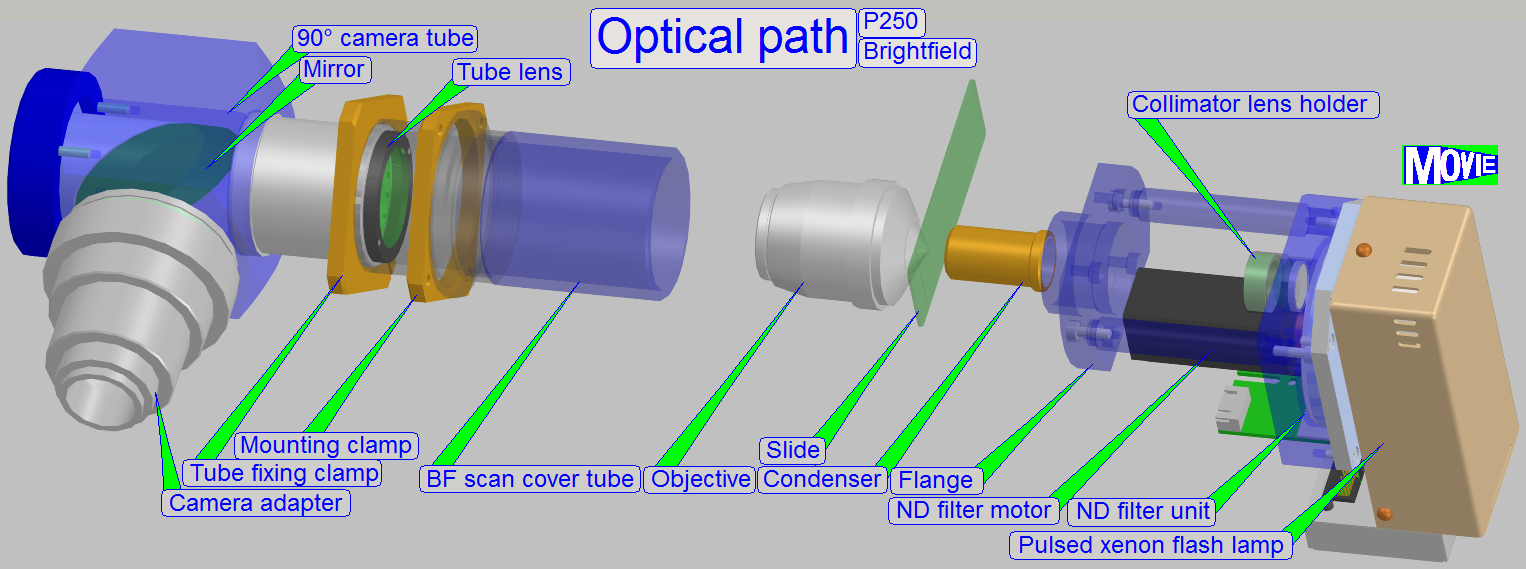
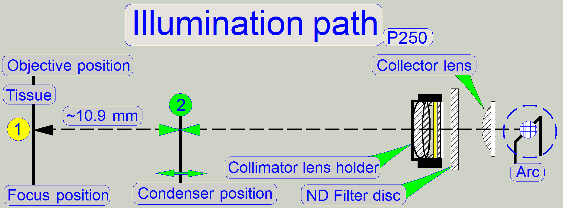
The emitted light of
the pulsed xenon flash light source, triggered by the software, crosses the “ND
filter” in the “ND filter housing”, the “Diffuser” and the “Yellow filter” in
the “Collimator lens holder”. All these filters are used to prepare the emitted
light of the light arc to illuminate the field of view (FOV) with the
homogeneity and intensity of the needed light wave lengths. The collimator lens
in the collimator lens holder produces parallel light rays and these are
arriving to the condenser.
The condenser concentrates the light to that area of the tissue that is
just observed by the objective pupil and the scan camera; the condenser illuminates
the scan camera’s field of view (FOV) during the brightfield scan procedure.
The light, passed thru the tissue is collected by the objective.
Into the space between objective and tube lens optical components can be
inserted, like the fluorescent filter block during the fluorescent scan
process; hereby the turret unit inserts the light from the fluorescent light
source to illuminate the tissue.
The image, created by the objective together with the tube lens, arrives
to the mirror of the camera changer unit. Depending on the position of the
mirror, the image is reflected to the camera position 2 for bright field scan
operation or to the camera position 1 if the fluorescent scan mode is selected.
The image can be modified in its size by using camera adapters with
different magnifications.
The reached magnification, seen by the CCD of the camera in the position
1 or 2 respectively is the result of the product of objective magnification and
camera adapter magnification.
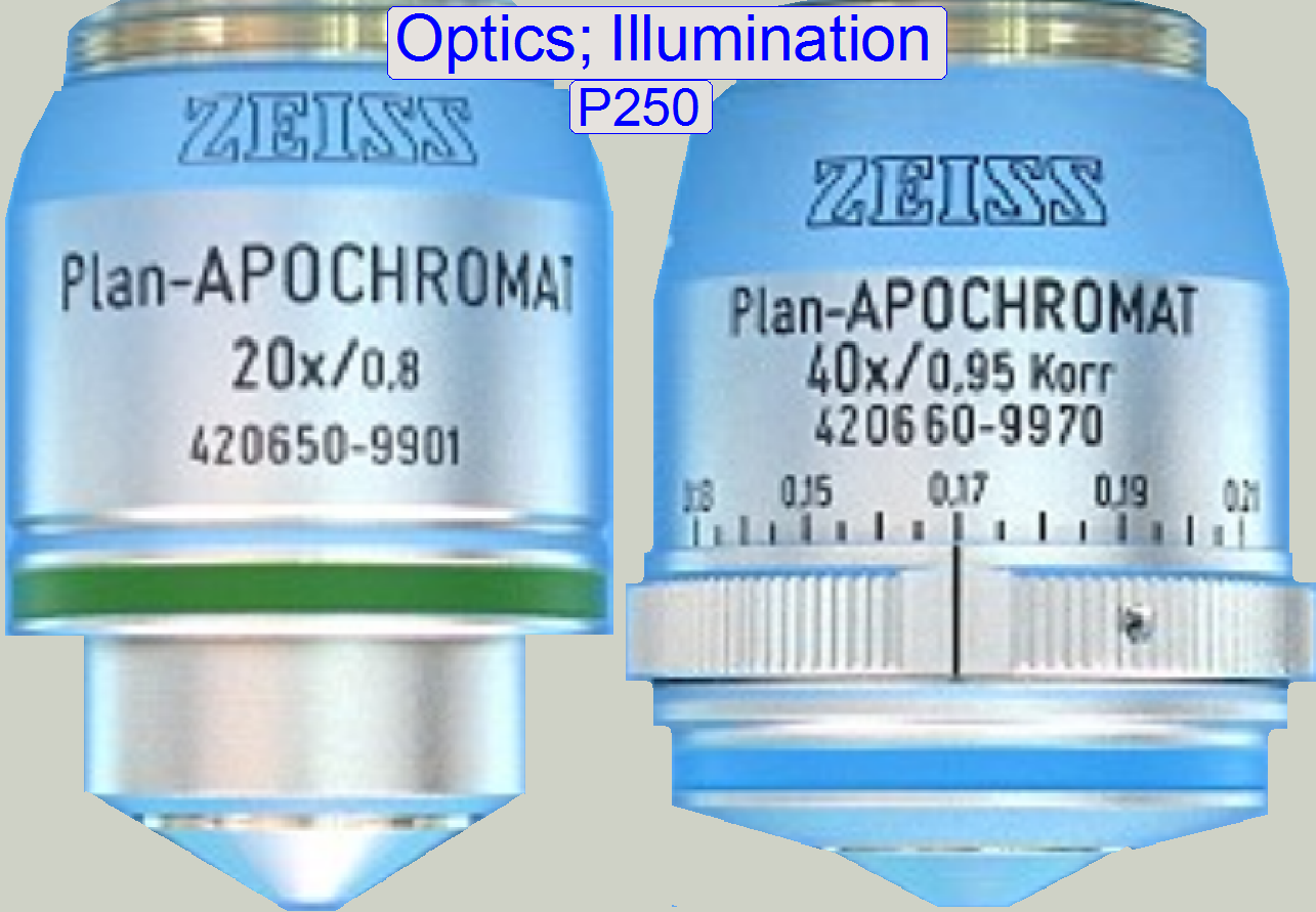
Example: If the objective
magnification is 20x and a camera adapter with a magnification of 0.63x is
implemented, the resulting magnification is 12.6x.
Remark: The
magnification of the camera adapter can not be varied as desired; the
construction of the image path and the size of the CCD of the used camera limit
the usable camera adapter magnification.
The CCD of the camera transforms the incoming light into electrical
charge, this is read by the electronics of the used camera; and the composed
data stream (the image) is transferred to the software.
![]() “Optical path and
Field Of View”
“Optical path and
Field Of View”
![]() “Influence of the camera
adapter” and “Useable
resolutions of scan (main) cameras”
“Influence of the camera
adapter” and “Useable
resolutions of scan (main) cameras”
 The flash light
source creates the light arc, used to illuminate the Field Of View (FOV) in the
brightfield scan mode.
The flash light
source creates the light arc, used to illuminate the Field Of View (FOV) in the
brightfield scan mode.
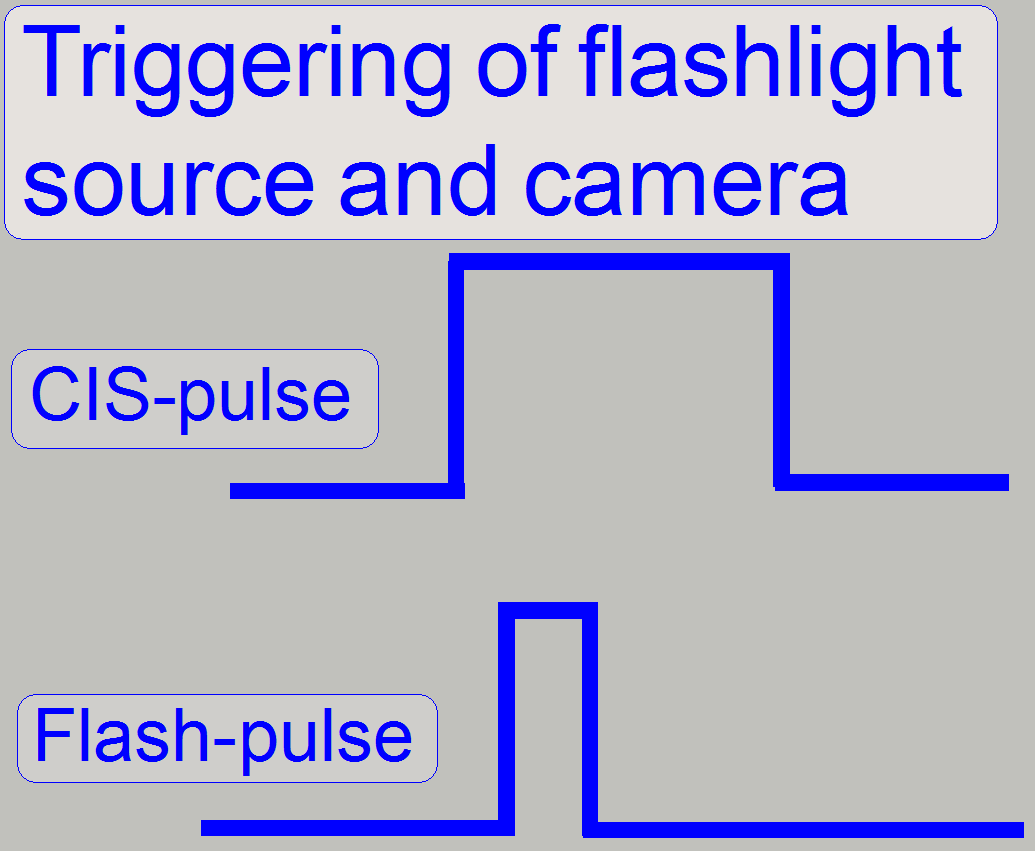
The pulse frequency can be more then 1kHz; it means, the scan camera
might make more than 1000 images /second.
To create the arc during the camera is ready; the flash light source, as
well as the shutter of the camera is triggered (synchronized) by the firmware
of the control electronics; the flash light pulse is started if the shutter of
the brightfield camera is already open.
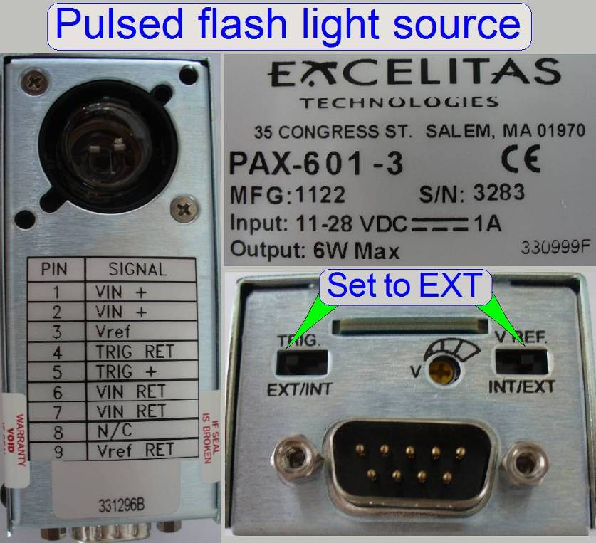
Configure the flash light source
Since the
software version 1.15 the units of the scanner are configured in the file
“MicroscopeConfiguration.ini”, section [Microscope].
The actual version of the flash light source in the scanner
Pannoramic 250 is “BrightfieldLightSourceType=FlashLight2010”.
[Microscope]
.
.
.
BrightfieldLightSourceType=FlashLight2010; brightfield scan procedure with 40x magnification is
impossible; see also the section [Microscope]
BrightfieldLightSourceType=FlashLight2012; brightfield scan procedure with 40x magnification is
possible; see also: “ND
filter unit” and “Upgrade
to software version 1.16”
Remark
If the Upgrade of the hardware to the software version
1.16 is done the value has to be modified to “FlashLight2012”
Important
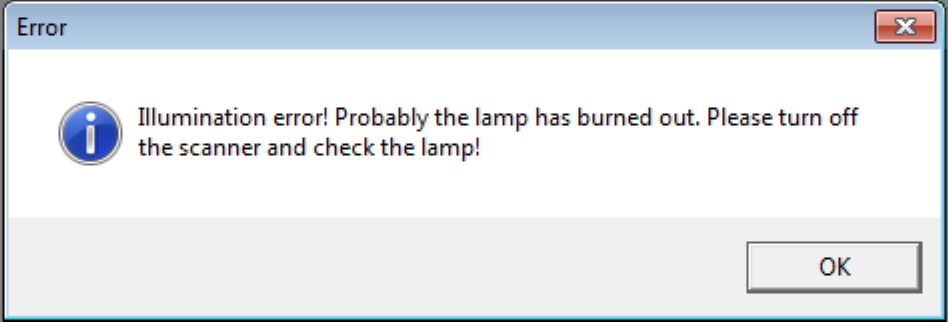 If the switch
“TRG” or “Vref” is not set to “External” the camera installation may be not
finished correctly in the dialog “Microscope settings” or the scan program
fails the camera installation with the error message.
If the switch
“TRG” or “Vref” is not set to “External” the camera installation may be not
finished correctly in the dialog “Microscope settings” or the scan program
fails the camera installation with the error message.
- The flash
light source does not need adjustments.
- Maintenance
is not required.
Neutral
density (ND) filter unit
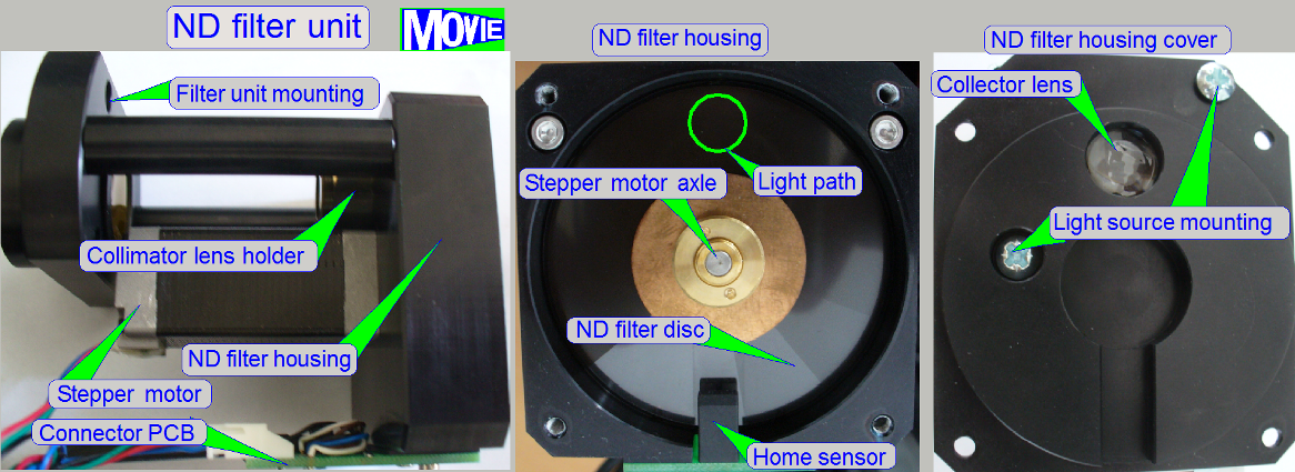 The ND filter unit is used
to adjust the brightness of the light, emitted by the pulsed light arc.
The ND filter unit is used
to adjust the brightness of the light, emitted by the pulsed light arc. - The Home
position of the stepper motor is defined by the transition from black to
white of the home sensor.
- The stepper
motor rotates the filter disc and so, the desired intensity of the
brightfield illumination can be found.
Mounting
· The flange of the
ND filter unit is mounted with four mounting bolts to the scanner plate.
Remove the mounting bolts and pull the entire ND
filter unit to the right.
·
No adjustments are needed
·
Maintenance is not required
Since the software version 1.15 the units of the scanner are configured
in the file “MicroscopeConfiguration.ini”, section [Microscope].
The actual version of the ND filter unit in the scanner
Pannoramic 250 is “NDFilterType=NDType2”.
[Microscope]
.
.
.
NDFilterType=NDType2; see also the section [Microscope]
ND filter disc
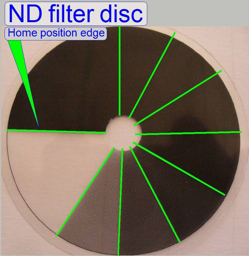 The ND filter disc consists of sectors with
different intensity of gray filter zones from white (fully translucent) to
black.
The ND filter disc consists of sectors with
different intensity of gray filter zones from white (fully translucent) to
black. - The
appropriate gray level intensity of the ND filter disc is selected by the
software during the calibration of the exposure time for the brightfield
camera; by rotating the disc with the ND motor, the intensity of the
illumination can be selected / adjusted.
- Usually, the
fifth sector after white is used, but due to the aging process of the
light arc (after some years) the used sector may be closer to white; this
way, the aging of the light source can be handled also.
Collector lens
The collector lens concentrates the light, emitted from the light arc,
and sends it to the ND filter.
·
No adjustments are needed
·
Maintenance is not required
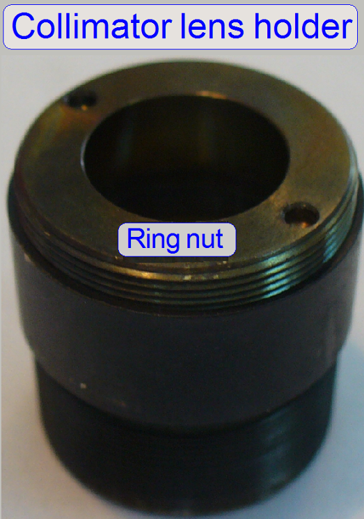
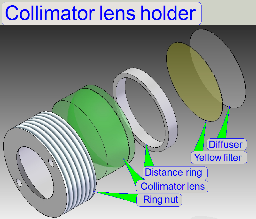
In microscopes the illumination
of the tissue is very important. The collimator lens holder contains the optics
to produce light with a high density and coherent rays; so, the field of view
can be illuminated evenly.

Components of
collimator lens holder
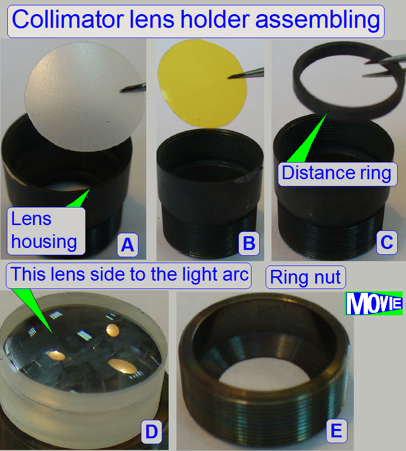
A.
Housing; insert
the diffuser foil first
B.
Insert the yellow filter next.
C.
Insert the distance ring; it keeps the convex surface
of the lens away from the yellow filter.
D.
Collimator lens; the surface of the thinner lens part
shows to the light arc.
E.
Ring nut
- Because the
blue and violet part of the emitted light is very much; the yellow filter
helps to create a “more white” light.
- The diffuser
foil insures the homogeneity of the light rays.
- The
collimator lens creates nearly parallel light rays.
·
No adjustments are needed.
·
Maintenance is not required.
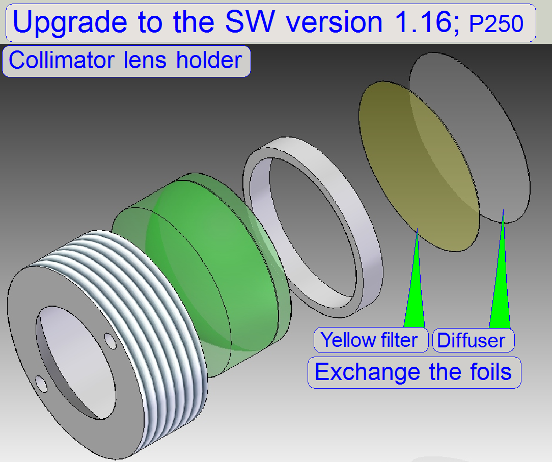
 Upgrade to software version 1.16
· Since
the software version 1.16 the user is able to scan tissues in the brightfield
scan mode with the 40x objective also.
· Because
the 40x objective needs “more light” in relation to the 20x objective, and the
actual construction of the illumination path can not deliver the required
amount of light, modifications in the illumination path are required; these
modifications are done with this upgrade.
Remark
If the Upgrade to the software version 1.16 is not executed, the
software version 1.16 can be started and used, but a brightfield scan procedure
with the 40x objective will be done in a very poor quality.
Upgrade
is required, if:
· The serial number of the scanner is ending with 02 (P250-00xx02) (or less) and in the file “MicroscopeConfiguration.ini”
the value of the parameter “BrightfieldLightSourceType=” is “FlashLight2010”!
 Upgrade is not required,
if:
Upgrade is not required,
if:
· BrightfieldLightSourceType=FlashLight2012;
the upgrade is already included!
Requirements
· The
diffuser foil and the yellow filter foil of the collimator
lens holder have to be exchanged into a version that absorbs less light.
Upgrade kit of 40xBF scan for P250; order number: HP-P250-PAX-0200
· A: In earlier developed scanners P250 the
“Yellow filter” was placed in this position! Please remove this filter if the
upgrade is done; see the image above.
With this solution, the 40x objective get “more light”
and the brightness of the virtual tissue, scanned with the 40x objective will
increase.
· Please
exchange the named foils and make the modifications as described in the chapter
“P250_upgrade the
illumination”
Finishing
If the Upgrade of the hardware to the
software version 1.16 is done the value of “BrightfieldLightSourceType=” in the
file “MicroscopeConfiguration.ini” has to be modified to “FlashLight2012”
BrightfieldLightSourceType=FlashLight2012; see also the section [Microscope]
Remark
Scanners with the serial number P250-00xx03 and higher already including this modification
and for these scanners the named upgrade is not required or if the value of
“BrightfieldLightSourceType=” in the file “MicroscopeConfiguration.ini” is
already modified to the value FlashLight2012!
![]() “Possible scan modes with different
cameras and magnifications in the software version 1.16; 1.17beta and 1.17
“Possible scan modes with different
cameras and magnifications in the software version 1.16; 1.17beta and 1.17
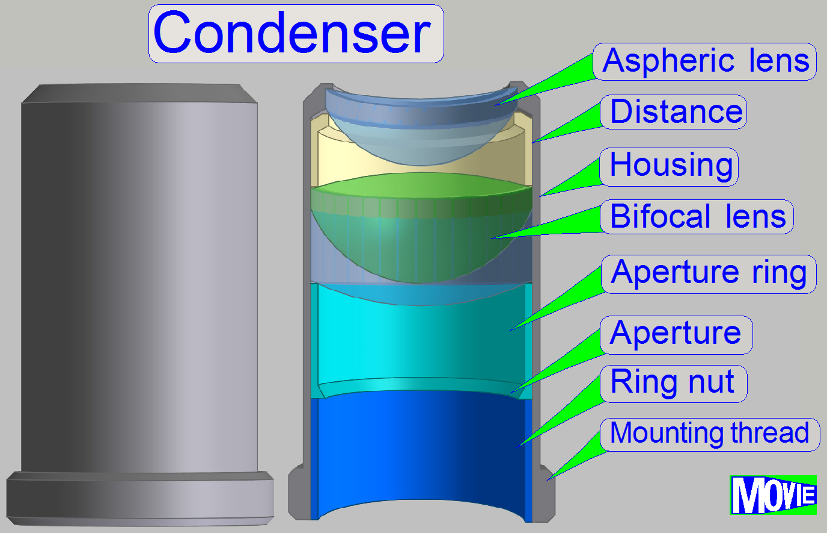
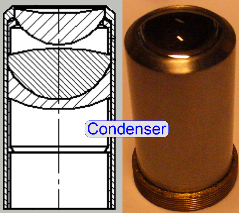
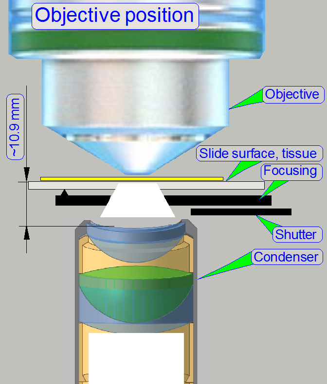
The condenser
concentrates the incoming light to the field of view (FOV).
Because the size of the
illuminated part of the tissue is critical, the condenser position can be
adjusted; the focus position is 10.9mm nominal.

Remark
 The best
illumination results would be reached if we would use an objective also to
illuminate the field of view; but because objectives are very expensive, a
condenser is used.
The best
illumination results would be reached if we would use an objective also to
illuminate the field of view; but because objectives are very expensive, a
condenser is used.
· In optical aspects
we can say, the condenser is a simplified objective.
·
See also “the focus unit with objective
changer” for the condenser
position adjustment.
·
Maintenance is not required
![]() Condenser
; Wikipedia
Condenser
; Wikipedia
 In
microscopes, the objective gathers the light, emitted from the tissue to be
observed and focuses the rays to produce an image. The character of the
objective is given by the
magnification and the numerical aperture.
In
microscopes, the objective gathers the light, emitted from the tissue to be
observed and focuses the rays to produce an image. The character of the
objective is given by the
magnification and the numerical aperture.
The position of the objective and the distance to the tissue is very
important to produce a sharp image. Because in Pannoramic scanners this
distance can be modified by moving the tissue
position (focusing) both positions, the objective position
and the nominal
focus position are important.
·
See also “the focus
unit with objective changer” for mounting the objective and
the objective position
adjustment.
Remark
Since the software version 1.16 the BF scan session may be executed with
the 20x or the 40x objective likewise.
![]() Upgrade to the
software version 1.16
Upgrade to the
software version 1.16
“Optical path and Field Of View”
![]() Objective;
©
Objectives_for_Microscopes_from_Carl_Zeiss.pdf; stored
Objective;
©
Objectives_for_Microscopes_from_Carl_Zeiss.pdf; stored
Important
If the scan program takes the compensation images
after the BF part of SlideScanner.exe was started and the program stops with
the error message
§
“The
parameter is incorrect”,
please check the components
of the optical path; the camera exposure time is outside the allowed range!
· The Flash illumination unit
illuminates the tissue
· The ND filter unit supports enough
light
· Condenser inserted and condenser
position is correct
· No filter block inserted in the
optical path (10th filter wheel position) and the filter wheel
hardware limits are set correctly
· Camera changer unit’s mirror stays
in the correct working position
If the scan software SlideScanner.exe shows the error
message
· “Error occurred” and stops working, please read the temperature
values with the service program!
· See
also: “Temperature
sensor, fan and fan control”
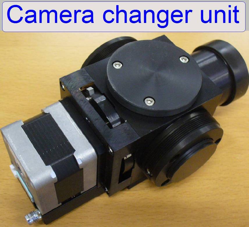
The camera changer
unit allows the mounting of 2 scan cameras at the same time and to deflect the
image to the appropriate scan camera, depending on the scanning mode.
- The camera
changer separates the common fluorescent (FL) and brightfield (BF) light
path, arriving from the tube lens to the appropriate camera, depending on
the mirror position.
- In the
brightfield scan mode, the image is reflected to the camera position 2 and
the camera position 1 is selected if the fluorescent scan mode is
activated.
- The
brightfield scan camera is always situated in the camera position 2 and
the fluorescent scan camera in the camera position 1.
- In the
standard version of the P250 the brightfield camera is the CIS-camera,
while in the fluorescent scan mode the PCO-edge
camera is used.
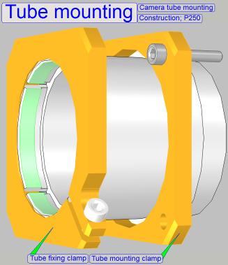
On the side near to the objective (tube mounting), the tube lens is
situated; this performs the image (together with the objective).
Into the space between objective and tube lens further optical components can
be inserted, like the filter block for the fluorescent scan. For best image quality, the tube lens should
be mounted into the camera tube until it stops!
The
functionality of the camera changer unit is discussed separately.
- Detailed
information can be found in the chapter “Camera
changer unit”
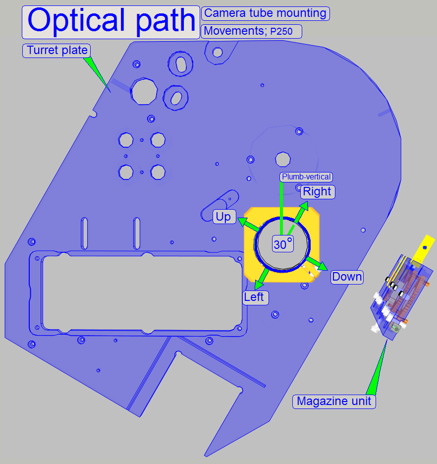 The camera changer
unit is mounted so, that the correct position can be adjusted. With this
adjustment the
chromatic aberration is corrected and minimized.
The camera changer
unit is mounted so, that the correct position can be adjusted. With this
adjustment the
chromatic aberration is corrected and minimized.
·
For adjustments, loosen the four clamp mounting bolts
to make the camera changer mounting barely moveable.
![]() “Chromatic aberration”
and “Reduce
chromatic aberration”.
“Chromatic aberration”
and “Reduce
chromatic aberration”.
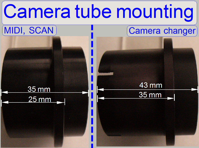 Attention
The camera changer mounting of the P250 differs in length from the
camera tube mounting in the SCAN and the
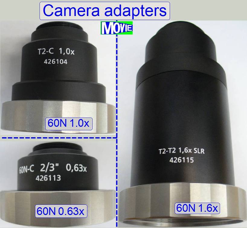
The camera adapter is
situated between the camera changer and the scan camera and offers the
possibility to insert lenses or other optical means like filters into the image
path.
If lenses are
inserted, the camera adapter modifies the image size and the magnification.
· The usable
magnification of the camera adapter depends highly on the scan
camera’s CCD size, its pixel resolution and the construction of the image path.
![]() “Influence of the camera adapter” and “Useable resolutions of scan (main)
cameras”
“Influence of the camera adapter” and “Useable resolutions of scan (main)
cameras”
Camera
adapter Carl
Zeiss; Product selection
Influence of the camera
adapter
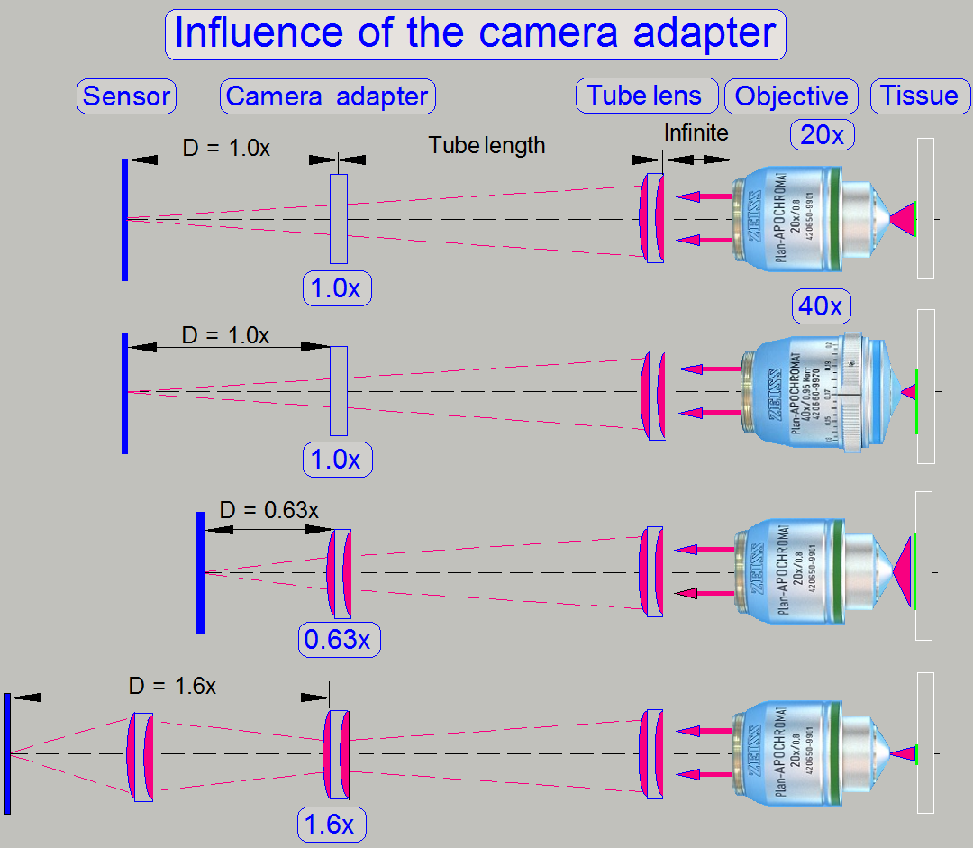
The useable magnification of the camera adapter depends on the size of
the sensor (useable geometry x and y in pixels), the used objective magnification
and the construction of the image path (Length of the camera tube).
· The resulting
magnification of the image path is defined by the product of Objective
Magnification multiplied by the Camera Adapter Magnification.
Example
If the Objective Magnification is 20x and the camera adapter
magnification is 0.63x the resulting magnification of the image path will be
12.6x.
Image
magnification = 20 x 0.63 = 12.6
Advantage
By reducing the image magnification,
the dimension of the FOV will be increased; the scan speed increases because
the number of FOVs to be scanned is reduced.
Disadvantage
The resolution of the virtual
tissue is reduced.
Conclusion
· The camera adapter
fits the image, seen by the objective into the focus of the camera sensor and
influences the resulting magnification of the image path and the size of the
FOV.
· If the camera
adapter magnification is 1x, then no lenses are inserted, and the sensor is in
the focus of the tube lens; the optical magnification is defined by the
objective magnification.
· If the camera
adapter magnification is 0,63x, then the lens of the camera adapter enlarges
the FOV; the resolution of the scanned tissue is decreased.
· If the camera
adapter magnification is 1,6x, then the optics of the camera adapter makes the
FOV smaller, and the resolution of the scanned tissue is increased!
Brightfield
scan (main) camera
 The charge coupled device
(CCD) of the scan camera transforms the incoming light (the image) into
electrical charge; and this is read out by the electronics of the camera.
The charge coupled device
(CCD) of the scan camera transforms the incoming light (the image) into
electrical charge; and this is read out by the electronics of the camera.
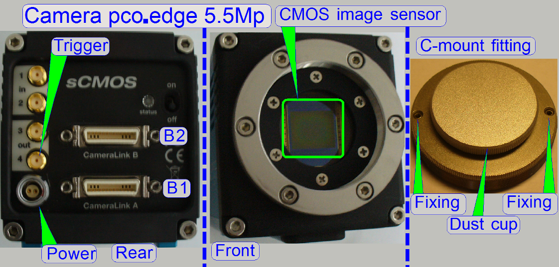
If the camera uses a CMOS image
sensor instead of the CCD device, the necessary modifications are handled
by the software.
·
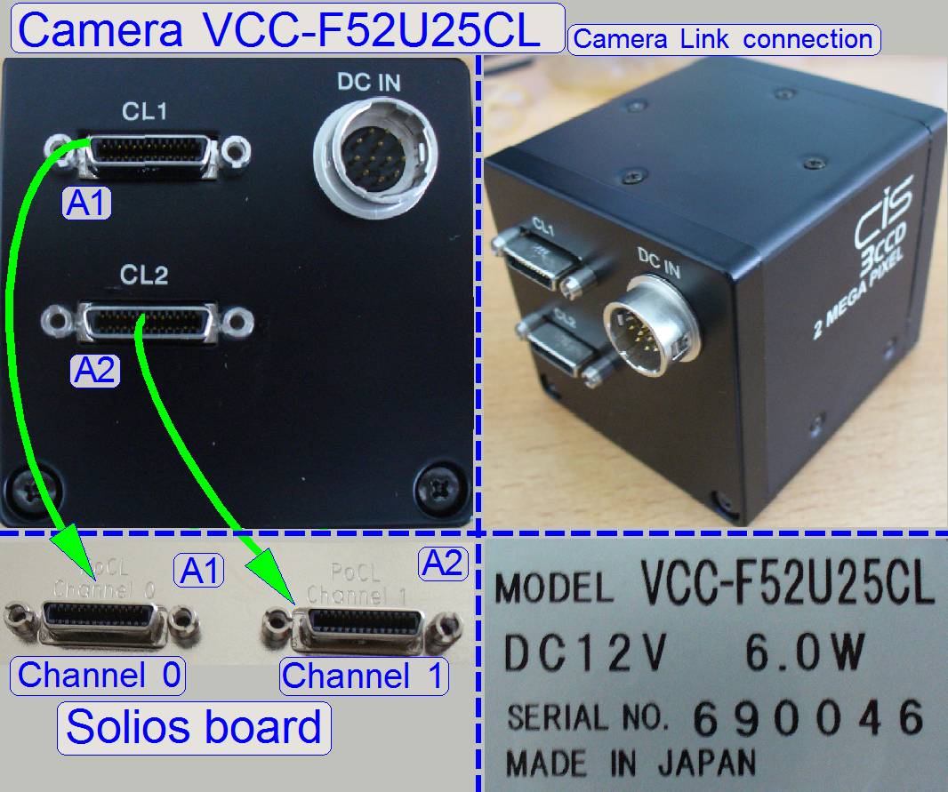
See also usable scan cameras and
the camera “CIS-VCC-F52U25CL”
·
See also: “Influence of the camera
adapter” and “Useable
resolutions of scan (main) cameras”
·
See also “Adjustment procedures” to “Adjust the camera
rotation angle”
·
“Introduction
to CCDs” ; ©NIKON, MicroscopyU
·
Matching
Camera to Microscope Resolution;
©NIKON, MicroscopyU; interactive
![]() “Possible scan modes with different
cameras and magnifications in the software version 1.16; 1.17beta and 1.17
“Possible scan modes with different
cameras and magnifications in the software version 1.16; 1.17beta and 1.17
 Optical path and
Field Of View
Optical path and
Field Of View
The pupil of the scan objective is very close to the tissue, so, the
small area on the tissue will be enlarged by the objective and the camera
adapter.
The seen area on the slide is always defined by the size of the camera’s
CCD; more precise, the effective number of pixels horizontal and vertical and
the optical means in the image path.
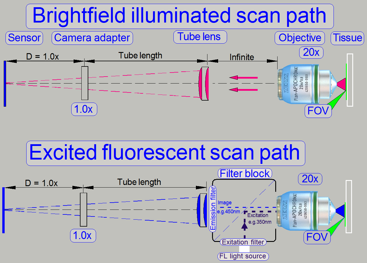
The objective type “Plan-Apochromat” requires a tube lens to create the
image. In opposite to other objective types, an infinite space exists between
the objective and the tube lens, in which the light
rays are parallel.
So, optical means, like the filter block in fluorescent
scan sessions can be inserted (by the help of the turret unit)
· The filter block’s
components do not affect the magnification of the image path!
·
See also “CCD versus
CMOS image sensor”.
·
What
is the difference between CCD and CMOS image sensors in a digital camera?
 usable scan
cameras and camera “PCO.edge”
usable scan
cameras and camera “PCO.edge”
Camera “AxioCam MRm REV.3”
“Adjustment procedures”
to “Adjust the
camera rotation angle”
General
Even illumination is important in microscopes and in
all of our scanners as well. A well adjusted illumination ensures that any
approved camera can be used properly with our scanners without further
adjustments.
 The
entire adjustment procedure of the optical path can be divided into two main
parts,
The
entire adjustment procedure of the optical path can be divided into two main
parts,
1. The
FOV illumination adjustment and
2. The
image path adjustment.
The adjustment parts can be done nearly separately from
each other, but always the illumination path is adjusted first and only then
will be adjusted the image path. If the adjustments are done, the entire result
should be checked again!
The adjustment is always done from the light source to
the tissue and from the tissue to the CCD of the camera. Because distances are
not measurable, the actual adjustment result is used to adjust the next
component. This procedure requires adjusting / checking the position of
previously adjusted components again!
Illumination adjustment
The goal of the brightfield illumination adjustment
is, to illuminate the FOV, seen by the objective pupil (and the scan camera) evenly
and with a density of light as much as required.
The adjustment of the illumination path is reduced to
the adjustment of the objective position and the condenser position.
The successful adjustment of the condenser requires
the nominal focus position; so the focus position of the objective must be
adjusted correctly before we can adjust the condenser position.
- If the FOV is not fully
and evenly illuminated, the quality of the virtual tissue becomes poor,
and
- If the illuminated field is too large, the exposure time of the
camera will increase and the scan procedure slows down, because the light
density is reduced.
· In the P250, the adjustment of the illumination path is reduced to the
adjustment of the objective position and the adjustment of the condenser
position.
Adjustment
procedure
Measure the thickness without cover slip of the slide
to be used for the objective position adjustment and calculate the number of
focus steps to be set in the focus unit; calculate the focus position; see
also: Check or
adjust the objective position
![]() Adjust
the objective and focus position
Adjust
the objective and focus position
1.
Start the scan program “SlideScanner.exe”,
2.
Insert a slide with the known focus
position for P250.
3.
In the tab “Focus” create a live view and
set the focus unit to the known focus position of the slide.
4.
Now adjust the objective position (with
the delivered wrenches) until the tissue becomes in focus.
5.
Tighten the counter nut of the objective
nut.
6.
Execute the auto focus command.
7.
The found focus position should not have
more then 50 steps in distance to the known or calculated focus position.
8.
If the deviation is too much, adjust the
objective position more precise.
Remark
In scanners, delivered after spring 2014 this
adjustment is simplified; see
![]() “Focus unit
with objective changer”; “Dismount or mount
the objective”; “Objective position”;
"Solution since
spring 2014", “Check or adjust the objective position”.
“Focus unit
with objective changer”; “Dismount or mount
the objective”; “Objective position”;
"Solution since
spring 2014", “Check or adjust the objective position”.
![]()
Adjust the condenser position
- Create a live view with the BF scan camera in the tab “Focus”
and adjust the condenser position.
![]() “Adjust the
condenser position”; “Condenser”.
“Adjust the
condenser position”; “Condenser”.
The entire image path adjustment includes the
adjustment of the following parts:
1. Objective position
This
adjustment ensures that tissues with different thicknesses can be scanned in
focus; of course, it was adjusted previously for the brightfield illumination,
but the objective position should be checked / adjusted again. If the objective
position is incorrect, the tissue or parts of it can not be scanned in focus;
see also “Check the optical path adjustments”.
2. Camera changer unit
position
The
position of the tube lens affects the color trueness of the scanned tissue; the
chromatic aberration becomes visible in more blue, and more red or yellow
colored cell borders on the opposite sides; see also “Chromatic aberration”
and “Adjustments”.
3. Camera rotation angle
If
the camera rotation angle is out of the limits, the stitching is not correct
and the borders of the FOV’s becoming visible in the virtual tissue with the
viewer program, the sample does not fit on the border of the FOV; see also “Stitching’.
 The
appearance of chromatic aberration can be divided into two main reasons:
The
appearance of chromatic aberration can be divided into two main reasons:
1. The used
materials (the composition of the glass) in the lens system; different
wavelengths of light will be focused to different positions; and
2. The
arrangement of the lenses to each other (centermost), with other words, the
straightness of the optical path (lens system).
- For any kind of aberration see “Optical
aberrations”
Chromatic aberration of a FOV is seen as unevenly
colored cell borders. Because the first item is given by the used optics (the
construction of the objective and lenses) and can not be affected by the
technician, we minimize the chromatic aberration by making the optical path
straight and centered.
For this purpose, in the P250 the position of the
tube in relation to the turret plate is modified (with loosened tube clamp
mounting bolts).
· After
the chromatic aberration adjustment was finished, the camera rotation
angle has to be adjusted (again).
 The
adjustment of the chromatic aberration is done in the real focus position and
in the center of the FOV to be observed.
The
adjustment of the chromatic aberration is done in the real focus position and
in the center of the FOV to be observed.
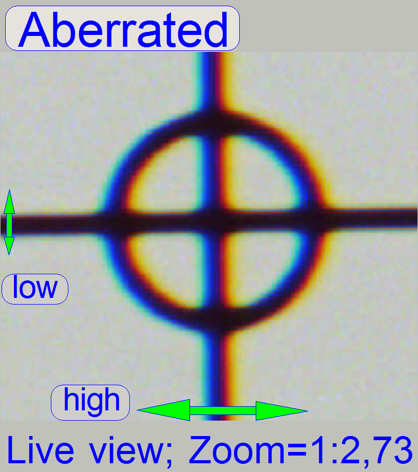
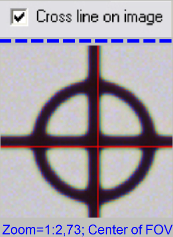
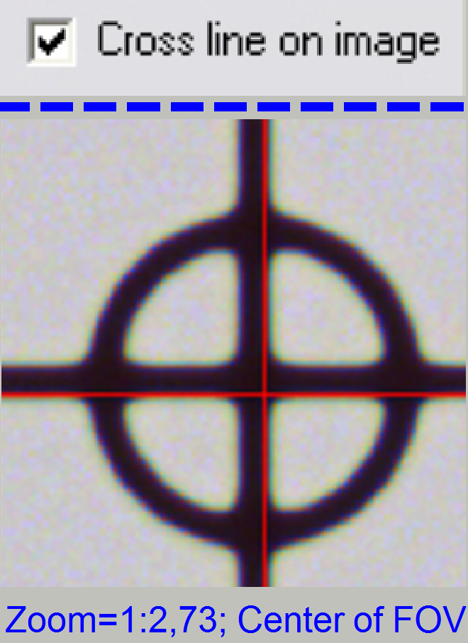
- A zoom factor of 2,73 is very helpful for this adjustment.
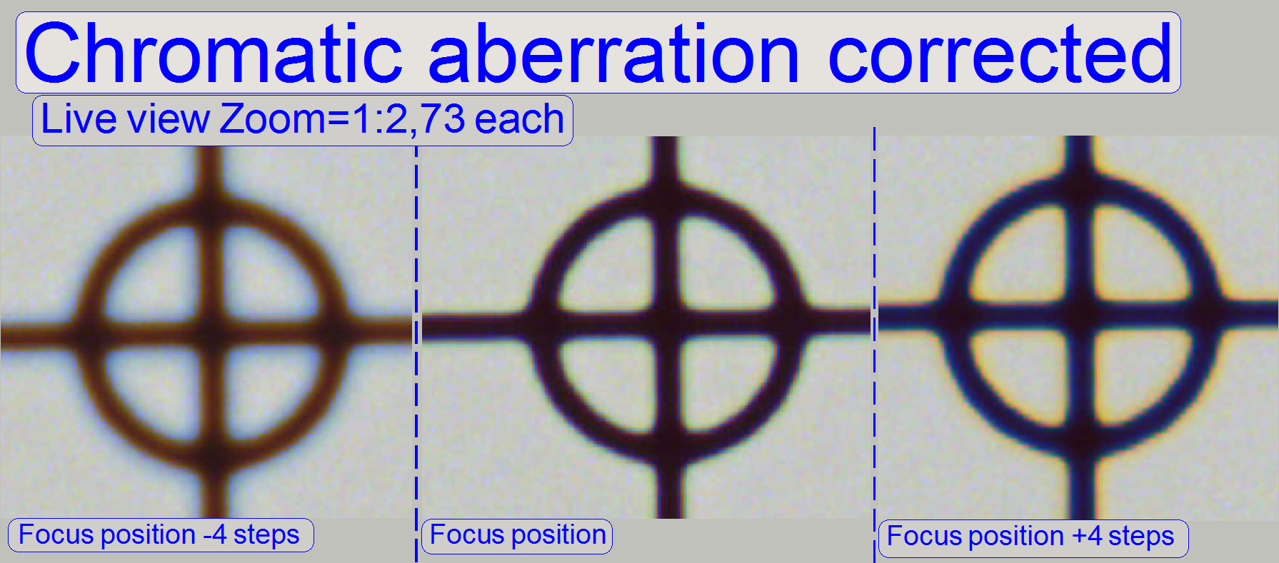
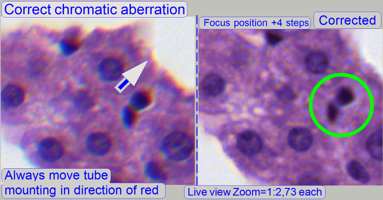
To check the result of the adjustment, the focus
position can be modified by some steps in positive or negative direction. In
this way, the correctness of the adjustment becomes more visible. If the yellow
color occurs evenly on the inner and outer part of the circle in the center of
the FOV, the adjustment is acceptable; see “Focus position +4 steps”.
The images are made in the focus position of the live
view, except otherwise specified and with a zoom factor of 2,73.
Chromatic aberration
becomes visible if the optical light path is not exactly perpendicular
(mirrors) or centered (lenses); it is corrected by different positioning of the
tube. For this purposes use a well visible tissue. To adjust the chromatic
aberration use / observe always the center of the FOV, never the border,
because the border has always more chromatic aberration as the center!
Example: If the otherwise
dark spots in the tissue have red or yellow boundaries on the top, and blue boundaries
on the bottom (see also above “Chromatic aberration”),
move the tube to the red, yellow direction.
1.
Start the program “SlideScanner.exe”, type
in the service password and load a slide with tissue.
·
Important: Check
the proper position of the slide in the specimen holder!
2.
After the preview is done, select the
option “Focus” and click on the button “Live view”, positioning tool ![]() and click inside the tissue and find a
well usable FOV with a lot of cells. Use the “Auto focus” button.
and click inside the tissue and find a
well usable FOV with a lot of cells. Use the “Auto focus” button.
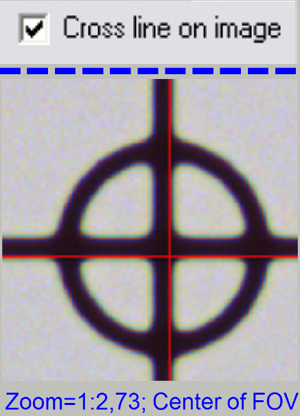
3.
Switch to “Service’ and “Microscope
control”; check the checkbox “Cross line on image”
4.
![]()
![]() Fit the camera
view to the size 1:1 with the button 1:1 and zoom in by using the zoom tool
until a zoom value of 2,73 is reached.
Fit the camera
view to the size 1:1 with the button 1:1 and zoom in by using the zoom tool
until a zoom value of 2,73 is reached.
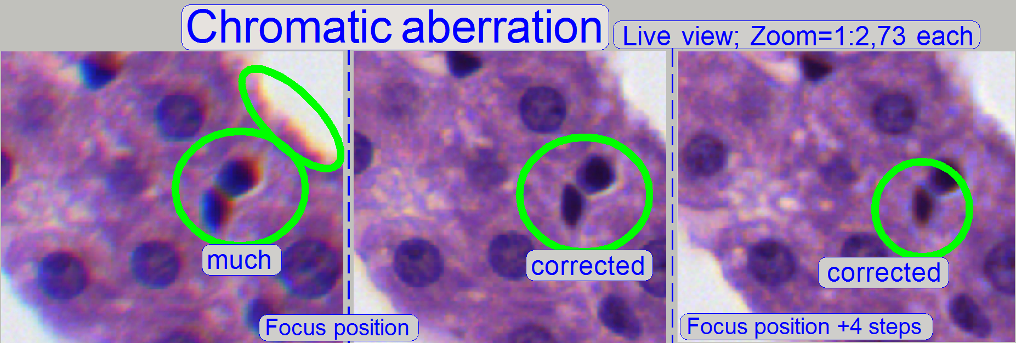
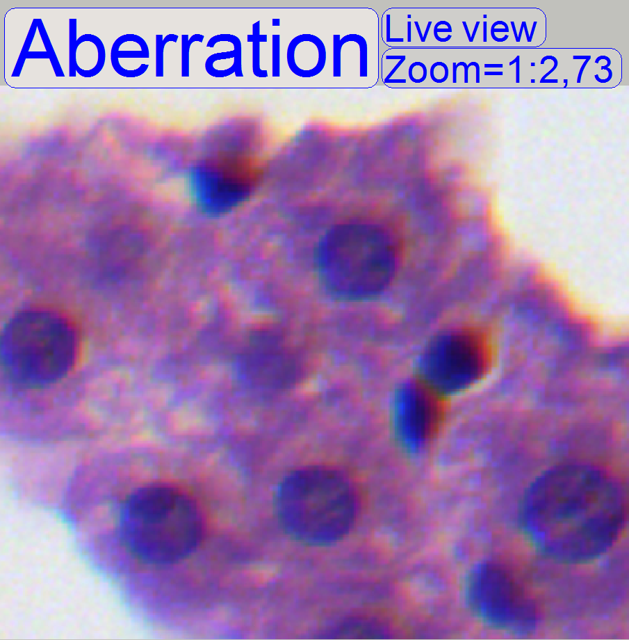
5.
If the zoom value is large enough (between
2.6 and 3), you can see something like this “Aberration”. If yellow, red or
brown colors are visible at the boundaries of spots on only 1 side and the
opposite side is blue, the optical system has chromatic aberration; check this
behavior on different positions of the tissue also.
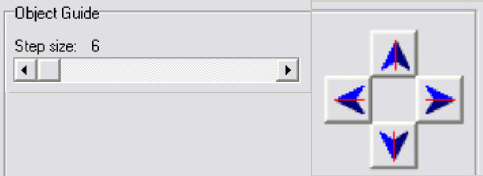
- Move the scroll bars so, that the cross is visible on the screen.
Observe always the center of the field of view; in the near of the cross.
To find the desired positions, set a step size in the tool “Object guide”
and move the stage by using the movement buttons.
6.
Loosen the tube fixing
bolts until the tube becomes just barely moveable.
7.
Move the camera changer on its mounting in the
direction, where the red or yellow color of the spot / cell occurs; see also “Position of
camera changer unit”.
8.
After pressing the “auto focus” button, use
a focus step size of 2 steps and go from the auto focus position in plus
direction. If the cell gets a brown / yellow ring in nearly constant thickness
the aberration seems to be adjusted.
9.
Repeat step 8 and check this result on
different positions of the same slide (tissue) with live view.
10. Scan a
tissue or a part of it and check the result with the program “SlideViewer”.
When you can find more positions where the aberration is visible always on the
same side of the cells, repeat from step 6.
11. When you can find parts of the tissue where
the chromatic aberration is visible on different sides of the spots, the
chromatic aberration seems to be adjusted.
12. Scan
two further tissues with different samples and check the results (repeat the
steps 10, 11).
13. If the
boundaries of the spots (see “corrected”) are colored evenly the optical path
is correct.
14. Tighten
the tube mounting bolts and check the result, by repeating the steps 8 to 11.
If necessary, repeat the steps from step 6.
15. Before
scanning tissues the scan program “SlideScanner.exe” has to be restarted,
otherwise stitching errors might occur.
After the chromatic aberration adjustment was
finished, the
camera rotation angle has to be adjusted (again).
Stitching errors have two main reasons:
1. Improper
adjusted camera rotation angle and
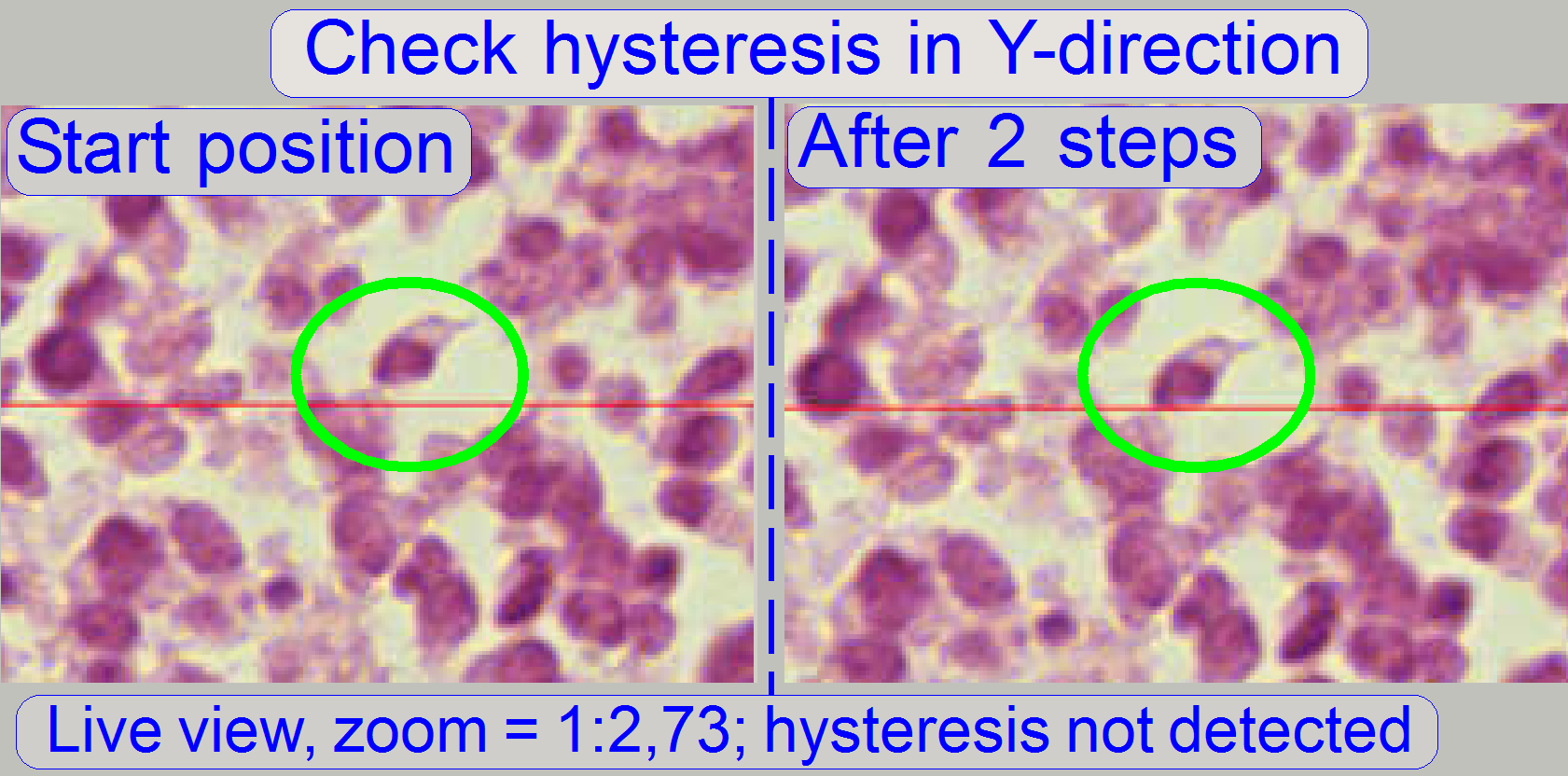
2. The hysteresis
in Y-direction is too much.
The camera angle becomes important during stitching.
If the angle of the scan camera is out of the limit, the stitching does not
working well, so the FOVs, seen with the viewer does not fit to each other. An acceptable
camera angle has less than +-0.5 degrees deviation from zero.
If the camera angle is correct and stitching errors
occurs, check the hysteresis in Y-direction.
![]() “Y- and
X-hysteresis” and “X-Y-stage unit”
“Y- and
X-hysteresis” and “X-Y-stage unit”
Adjust
the camera rotation angle
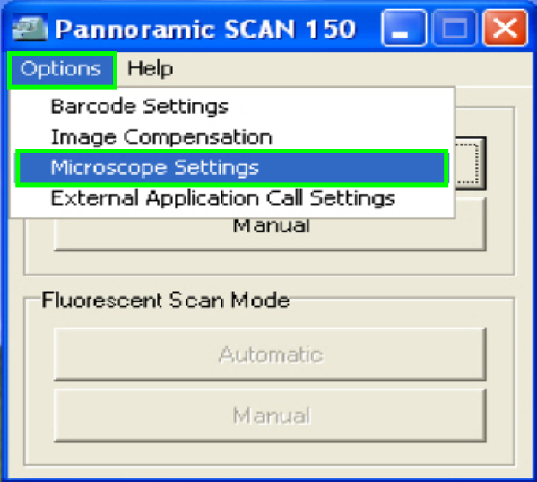
In the selector menu and ‘Options” start the item
“Microscope settings”.
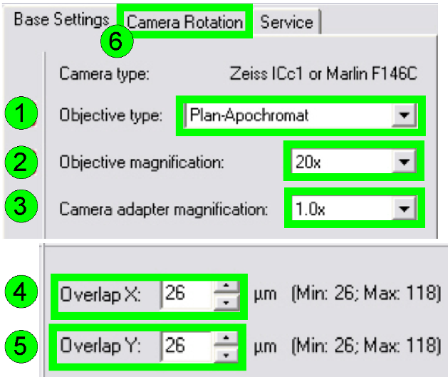 In the
tab “Base settings” set the values for the parameters numbered with (1)-(5) as
these are true for the scanner to be set up; then change to the tab “Camera
rotation” (6).
In the
tab “Base settings” set the values for the parameters numbered with (1)-(5) as
these are true for the scanner to be set up; then change to the tab “Camera
rotation” (6).
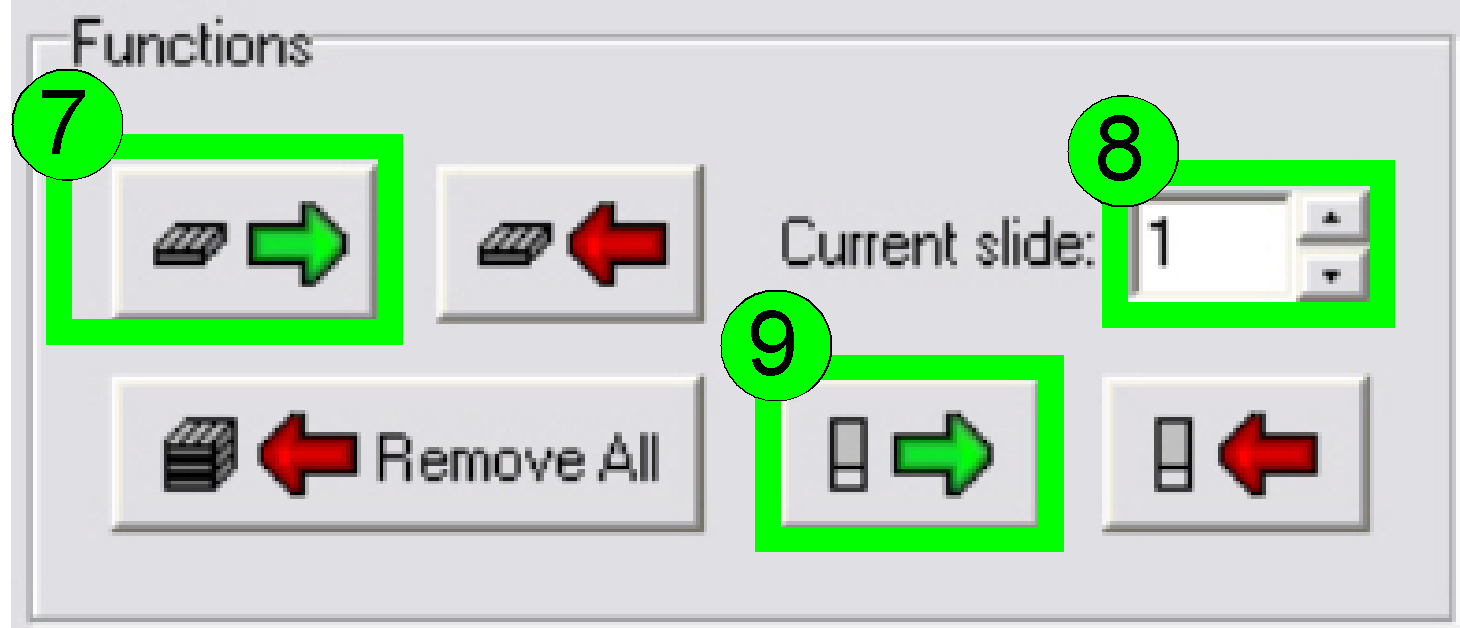 Load a magazine (7), select the
desired slide position (8) and insert the slide (9).
Load a magazine (7), select the
desired slide position (8) and insert the slide (9).
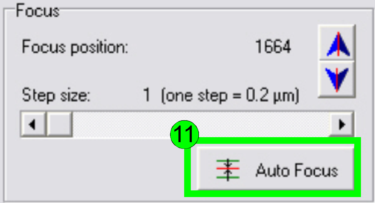
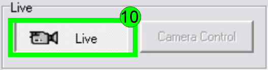 In the
preview window find a FOV with tissue; press the button “Live view” (10) and
“Auto focus” (11). If the focus position is found, click outside the tissue and
inside the cover slip on a “white” position.
In the
preview window find a FOV with tissue; press the button “Live view” (10) and
“Auto focus” (11). If the focus position is found, click outside the tissue and
inside the cover slip on a “white” position.

Set the “Auto exposure time” and the “White balance”
by clicking on the appropriate icon on the lower screen border.
Click inside the tissue and find a well usable FOV
with cells.
Find the focus position (11).
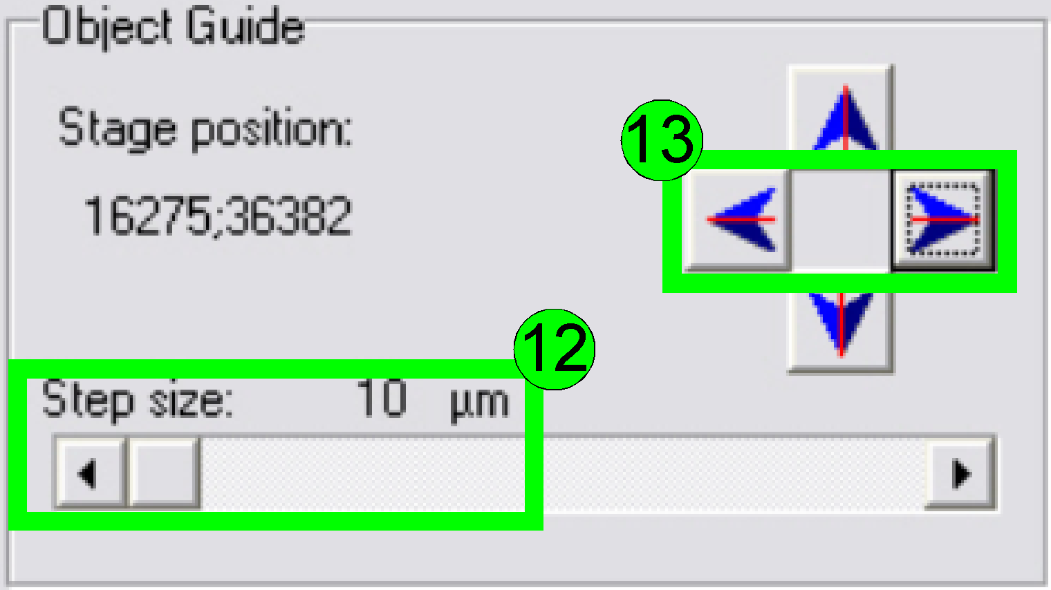 Select
a “Step size” of 10 or 20 µm (12) and move the object guide to the left or
to the right as desired (13) and observe the movement of a cell near to or on
the horizontal red line. If the cell deviates from the red (horizontal) line in
the center upward or downward respectively, correct the camera angle
continuously (by moving the camera adapter on its mounting) until the cell
moves on the red line (14) or exact parallel to it.
Select
a “Step size” of 10 or 20 µm (12) and move the object guide to the left or
to the right as desired (13) and observe the movement of a cell near to or on
the horizontal red line. If the cell deviates from the red (horizontal) line in
the center upward or downward respectively, correct the camera angle
continuously (by moving the camera adapter on its mounting) until the cell
moves on the red line (14) or exact parallel to it.
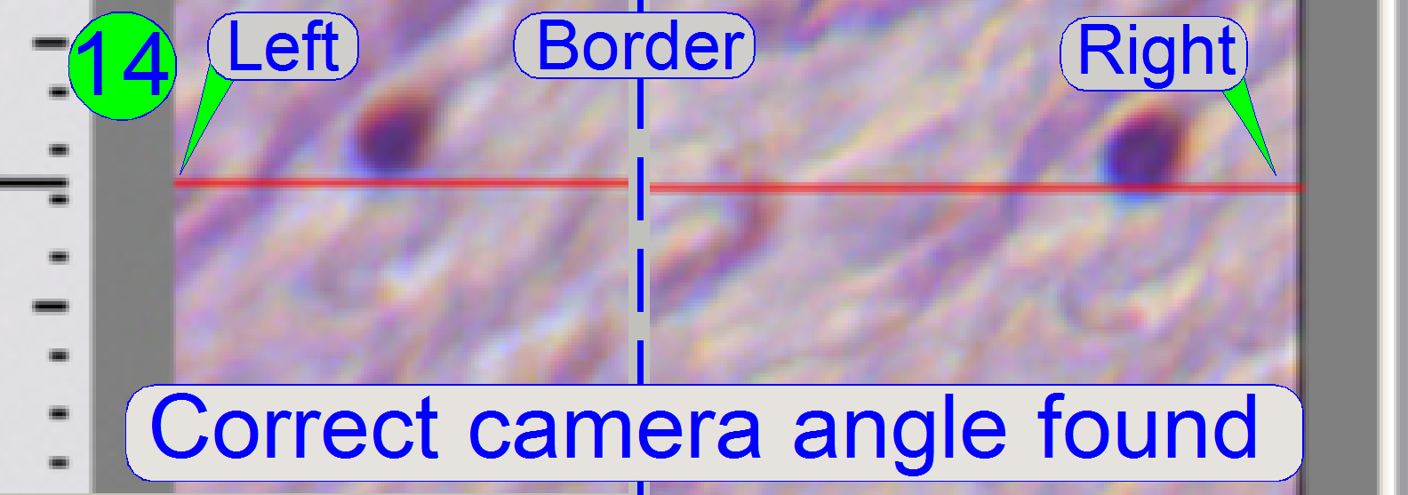
If the cell moves from the left border to the right
border of the screen (or reverse) nearly on the red line, the camera angle is
correct (14).
 Press
the button “Measure Camera Rotation” (15).
Press
the button “Measure Camera Rotation” (15).
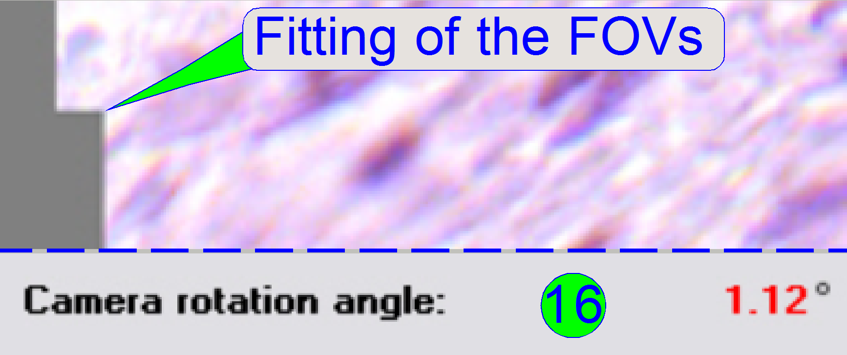
Now the program arranges two FOVs to each other and shows
so graphically the fitting of the FOVs in the centre of the live view; the
numerical value of deviation is shown in the lower part of the left sided
adjustment window. If the value of the rotation angle is shown in red, the
position must be adjusted more precise (16). Correct the camera position and
press the button “Measure Camera Rotation” (15) again, until an acceptable
angle is found.
 If the
rotation angle can be accepted, the angle value is shown in black (17); an acceptable
value has less than 0.5degrees in deviation.
If the
rotation angle can be accepted, the angle value is shown in black (17); an acceptable
value has less than 0.5degrees in deviation.
 Save
the calculated rotation angle to the appropriate file by pressing “Save” (18);
and in the next following dialog answer with “YES” to save the file.
Save
the calculated rotation angle to the appropriate file by pressing “Save” (18);
and in the next following dialog answer with “YES” to save the file.
Leave the menu “Options” by clicking on “Exit”.
Check the optical path adjustments
Objective and
focus position
As discussed previously, the correct objective and
focus position is important to be able to scan tissues of different thicknesses
in focus.
This fact we are using to determine the correct
objective position.
1. Find
at least three, better are 5 slides with tissue of different thickness and of
different kind.
2. Insert
the (next) slide; check the correct position of the slide in the specimen
holder!
3. Produce
a live view of the tissue, press “Autofocus” and notify the focus position.
4. Repeat
step 3 on 5 different positions of this tissue; the distance of the positions
should be as much as possible.
5. Calculate
the average focus position of this slide and notify it.
6. Repeat
from step 2 until the average focus position of all the selected tissues is
determined.
7. Calculate
the average focus position of all the tissues.
8. If the
average focus position deviates more then 50 steps from the nominal focus
position, calculated with the used slide thickness, the objective position
should be corrected.
9.
If the objective position was modified,
please check the correctness of the condenser position again.
 Check
the correct condenser position in the focus positions -300, 500 and 1300 steps.
There must not be significant differences.
Check
the correct condenser position in the focus positions -300, 500 and 1300 steps.
There must not be significant differences.
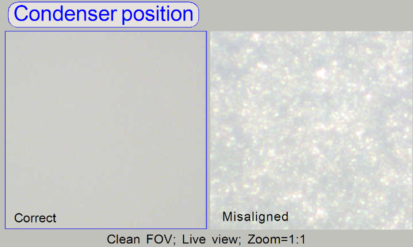
· For
best scan results, the clean FOV should be evenly illuminated over the entire
focus range.
· If the
condenser is misaligned, the roughly surface of the diffuser becomes visible!
Remark
“Clean FOV” means a Field of View, seen by the scan
camera without tissue, dust or dirt, between slide and cover slip.
![]() “Adjust the condenser
position” and “Focus unit”
“Adjust the condenser
position” and “Focus unit”
General
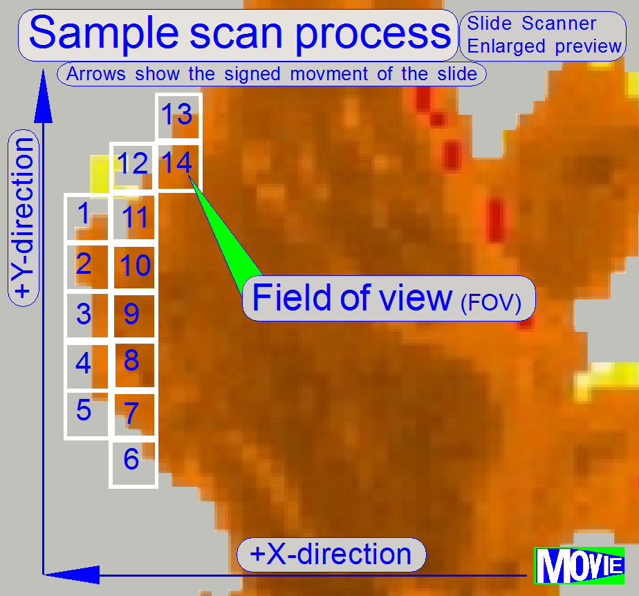
The
software divides the sample to be scanned, seen by the preview camera into
fields of views; the size of the FOV depends on the resolution and the size of
the scan camera’s CCD and the magnification of the camera adapter. Each field
of view contains a small part of the neighbor FOV. In this way, stitching
becomes possible. Because the capturing of the FOV’s is done on a meandering
course, the Y-direction is often changed. If the hysteresis in Y-direction is
too much, stitching will not work correctly; therefore, we have to check the
hysteresis in Y-direction. The maximal allowed hysteresis is 4 μm (=4
motor steps). We comment that this hysteresis decreases itself by some motor
steps after some sample scan procedures, even if the X-Y-stage is brand new.
Because the X-direction is never changed during a
sample scan process, the X-hysteresis is not critical and can be some steps
more (max: 8 steps).
· To
reduce the Y-hysteresis, see also “X-Y-stage
unit” and “X-
and Y-carriage drive unit”.
Watch video: “Tissue scan process”
(P250)
Check the maximal hysteresis in
Y-direction
 Start the
program “SlideScanner.exe” with the service password. In the tab “Focus”
produce a sharp life view.
Start the
program “SlideScanner.exe” with the service password. In the tab “Focus”
produce a sharp life view.
In the tab “Service” select “Microscope control”. In
the part of the X-Y-control select a step size of two steps and go upward,
until the tissue moves.
Now go in opposite direction and count the clicks
until the tissue moves again. If more then 3 clicks are required, the
hysteresis is too much.
The correction of the hysteresis can not be done in the field.
![]() “X-Y-stage
unit” and “X-
and Y-carriage drive unit”.
“X-Y-stage
unit” and “X-
and Y-carriage drive unit”.
Chromatic
aberration
Scan a tissue and check the chromatic aberration with the
Slide Viewer program.
![]() above “Chromatic aberration”.
above “Chromatic aberration”.
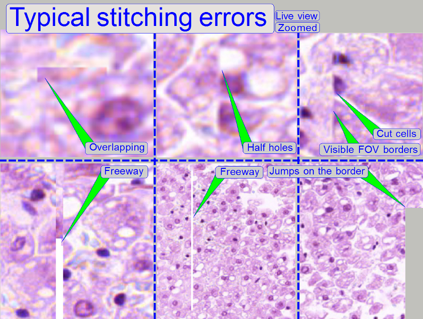
Stitching
Scan a tissue and check the stitching with the Slide
Viewer program for stitching errors. See also “Typical stitching errors” in
the description above.
The stage skew check is used to determine the
inclination of the specimen holder and so the inclination of the slide. If the
inclination is too much, parts of the tissue are in focus while other parts of
the same FOV are not in focus.
The Stage skew check should be done:
- If the parallelogram was removed.
- If the parallelogram or the specimen holder was exchanged.
- If the entire X-Y-stage unit was changed.
- If the Focus unit was exchanged.
- If any spare part was changed and this spare part is in connection
with the perpendicularity of the optical axis to the slide.
- If the mounting bolt positions or the adjustment bolts position of
the parallelogram was altered.
- See also “Parallelogram
adjustment”.
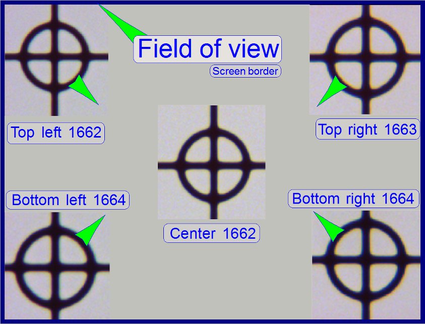
To check the inclination angle of the specimen holder,
a series of screen shoots is done of a cell (circle) in the center of the FOV
and in the upper / lower and left / right corners respectively.
There are 7 screenshots taken in each position; 3
before the found auto focus position and 3 screenshots after the auto focus
position. Then find the screenshot of each position where the cell (circle) is
most in focus. If there is a difference, more then 2 focus steps to the found
focus positions, the specimen holder is slanted and has to be adjusted; this
adjustment can not be done in the field; probably the specimen holder or the
parallelogram is deformed.
Important: Always check the
proper position of the slide in the specimen holder first.
See also the “X-Y-stage
unit”.
In the example on the right the most difference is 2
steps and therefore the inclination of the specimen holder is acceptable.
1.
Start the program SlideScanner.exe with
the service password, insert the slide with circle, produce a live view and
press auto focus.
·
Important: Always check the proper
position of the slide in the specimen holder.
2. Find
the circle and bring it nearly into the center of the live view, press auto
focus.
3. Select
the tab “Service” and “Microscope control”.
4. Select
a step rate about 5 or 10 steps for the object guide.
5. Check
the checkbox “Cross line on image” and with the object guide movement buttons
bring the center of the circle to the center of the cross; the circle is now in
the center of the FOV.
6. Uncheck
the checkbox “Cross line on image”
7. Zoom
in until a value of 2,73 is reached.
8. Grab
the center of the circle (FOV) into the middle of the screen.
9. Memorize
the auto focus position and go backward with the focus position about 20 steps;
and then go forward to the auto focus position -3 steps with a step size by 1.
This way, the probably hysteresis of the focus unit and other mechanics is
eliminated.
10. Make a screenshot
and create a directory named “Focus stack”, name the file as C (for center) and
the number of the actual focus steps, e.g. “C 1659” if the
memorized focus position was 1662 steps and save the file into the directory
“Focus stack”.
11. Increment the
focus position by 1, make the next screenshot and save the file.
12. Repeat step 11
until all the 7 screenshots are done.
13. Now move the
circle with the object guide positioning buttons to a corner position, e.g. to
the upper left corner. The corner is found correctly if the circle can not be
grabbed in direction to the center (see also the green arrows in the image
above “The field of view”).
14. Repeat the steps
from step 9 logically until the screenshots are done in all four corners. The
file names should be UL xxxx, LL xxxx, LR xxxx and
Find the screenshot with the circle most in focus for
each series and notify the file names.
Decide the specimen holder has either to be adjusted
or not as shown in the image above “The field of view”).