X-Y-stage unit; P250
For
technicians and partly for sales managers!
This description handles the functionality and instructions to install
and to check the X-Y-Stage unit for the scanner "Pannoramic 250".
The explanations are based on the software version 1.15.
Contents
Check the
hysteresis in Y-direction
The X- and Y-carriage
drive unit
Dismount and mount
the carriage drive unit
·
For safety regulations regarding
human health and scanner functionality please refer to: Precautions
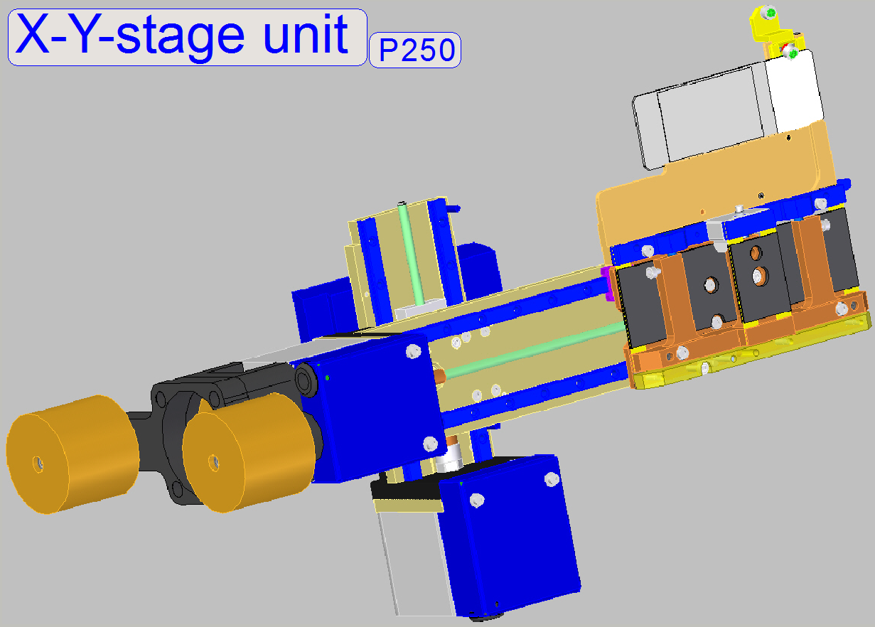
The X-Y-Stage unit is used to
reach positions on the slide;
to move the specimen holder in X- and Y-direction for the slide load or unload
action and to move and secure the slide during the scan process. The drive for
the movements is realized with stepper motors.
The X-Y-Stage unit is mounted
with a dovetail mounting, so the correct position is reached again
automatically after the unit was removed and mounted again; see also ”Exchange the X-Y-stage
unit”.
 In relation to the X-Y-stage
unit of the SCAN 150, the following modifications are implemented:
In relation to the X-Y-stage
unit of the SCAN 150, the following modifications are implemented:
The exchange of the X-Y-Stage unit is
necessary:
- If one of the stepper
motors is faulty.
- If the
maximal allowed hysteresis
of 4 steps in Y-direction is exceeded.
- If the shape
of any part is deformed or a part is broken.
- If the
X-Y-Stage unit has any fault and
you are unable to fix it.
- In any cases,
please refer first to the chapter “Before
you start to replace units”!
Requirements
- Service
program for slide scanners version 1.14 or higher (SlideScannerService.exe) with
actual license file.
- Slide scanner
and Slide scanner Viewer software (SlideScanner.exe,
Slide
Viewer.exe) with dongle or actual license files.
- 1.5, 2.5, 3
and
- Hardware and construction
knowledge of Pannoramic scanners.
 Attention:
Do
not mix the versions of SlideScanner.exe and SlideScannerService.exe! Always use these programs with the same
version number. Otherwise the SlideScannerService.exe program could produce unwanted results and SlideScanner.exe does not work correctly or even freeze!
Attention:
Do
not mix the versions of SlideScanner.exe and SlideScannerService.exe! Always use these programs with the same
version number. Otherwise the SlideScannerService.exe program could produce unwanted results and SlideScanner.exe does not work correctly or even freeze!
Since the software version 1.15 the
units of the scanner are configured in the file “MicroscopeConfiguration.ini”,
section [Microscope].
 The actual version
of the X-Y-stage unit in the scanner Pannoramic 250 is
“ObjectGuideXYZType=OGXYZ_FLASH3”.
The actual version
of the X-Y-stage unit in the scanner Pannoramic 250 is
“ObjectGuideXYZType=OGXYZ_FLASH3”.
[Microscope]
SerialNumber=xxxx
MicroscopeType=3DMic9
ScanCameraType=
PreviewCameraType=CVrmc_m8_pPro
BarcodeReaderType=PreviewCamera
LoaderType=SL_9Mag_25Slide_Sensor_Vertical
CameraChangerType=CC_None
ReflectorTurretType=RT_None
BrightfieldLightSourceType=FlashLight2010
ObjectiveChangerType=OC_2Pos
ObjectGuideXYZType=OGXYZ_FLASH3;
Adjustment
procedures are based on this version, except explicitly declared otherwise.
FlashUnitType=FlashUnit_Type2
NDFilterType=NDType2
PreviewLightType=PreviewLightUnitType_Type1
PowerSwitchBoardType=PowerSwitchBoard_Type1
Remark
ObjectGuideXYZType=OGXYZ_1; not used today; the specimen
holder can hold slides with a thickness of 1.0mm nominal; the stepper motor
contains its control electronics (the same construction as in the PSCAN150).
ObjectGuideXYZType=OGXYZ_FLASH2; the Y-direction is 23 rotor revolutions
long, the specimen holder can hold slides with a thickness of 0.95 … 1.20mm, the
control of the stepper motor is realized in the “X-, Y-, Z-, ND- and flash”
controller; a darkfield preview can not be created.
ObjectGuideXYZType=OGXYZ_FLASH3; this is the most recent version today; the
Y-direction is now 28 rotor revolutions long, it is prolonged by about 16mm (5
rotor revolutions) in relation to the previous version; the specimen holder can
hold slides with a thickness of 0.95 … 1.20mm; now a darkfield preview can be created.
This value is used to define
the version P250 Flash!
ObjectGuideXYZType=OGXYZ_FLASH4; Additional to the specification of the
version “OGXYZ_FLASH3” the firmware of the X- and Y-stepper motor driver is modified
to reach the scan speed of 130fps since the software version 1.17. Use this
value only, if the firmware upgrade is done!
This value is used to define
the version P250 Flash2 also!
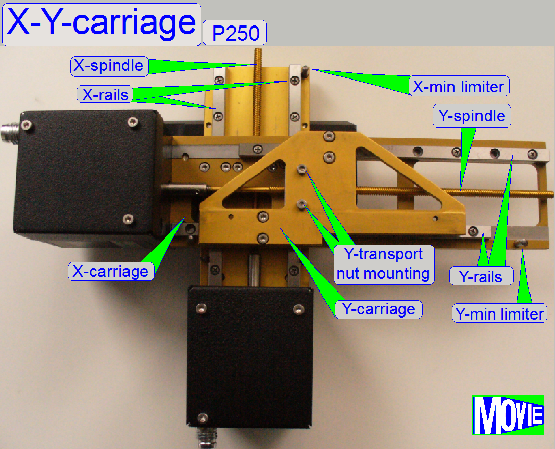 The rotor drives the
transport nut via the spindle. The transport nut is mounted to the carriage
which is moving on the rails.
The rotor drives the
transport nut via the spindle. The transport nut is mounted to the carriage
which is moving on the rails.
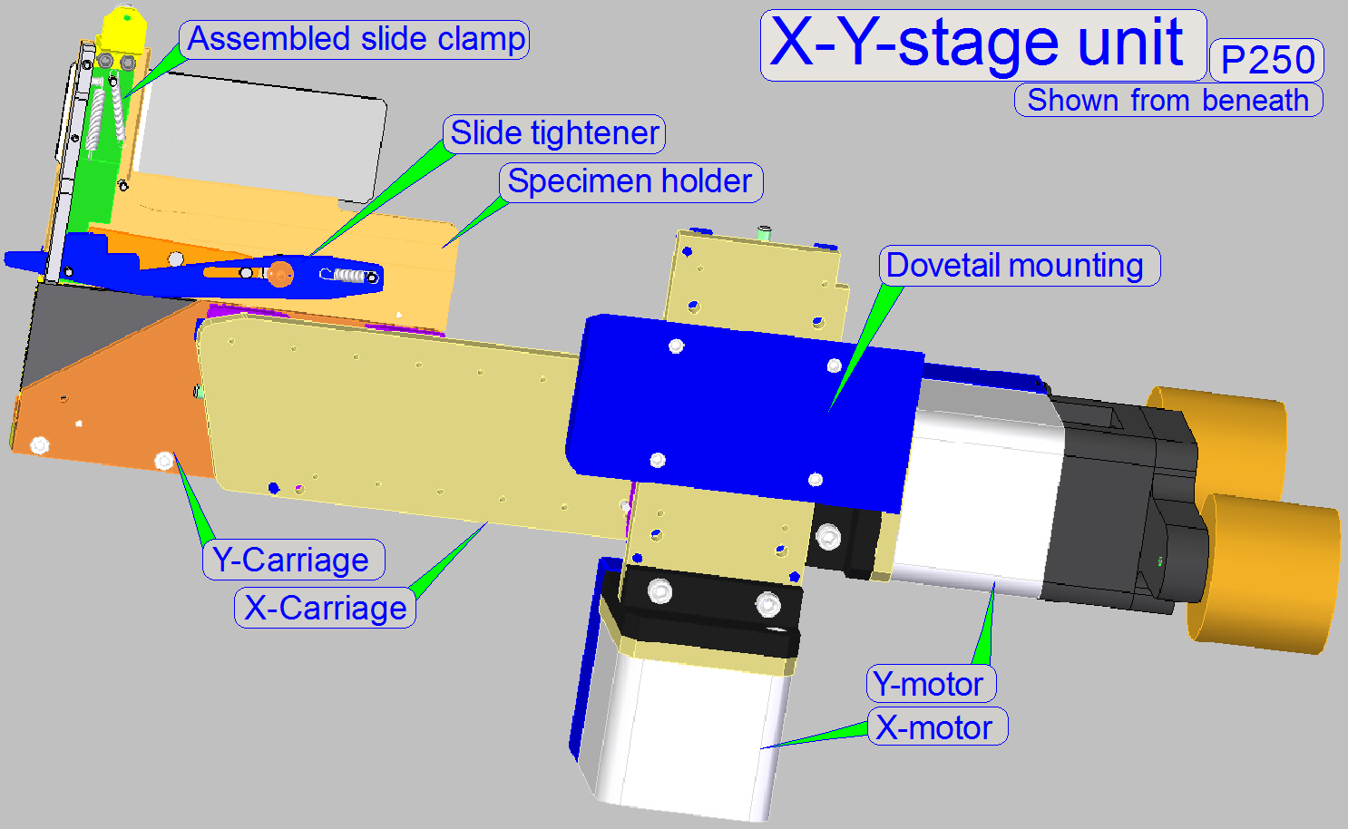
The X-carriage contains the entire Y-unit.
The Y-carriage moves the parallelogram with the specimen holder.
· The achieved
resolution in X- and Y-direction is: 1μm/rotor
step
· The guaranteed
movement range of the X-carriage is 28800 rotor steps (it means 28.8mm)
· The guaranteed movement
range of the Y-carriage is 89600 rotor steps (it means 89.6mm)
· The parts and
units of the carriages need neither maintenance nor mechanical adjustments.
![]() “Limiters”
“Limiters”
Components
and construction
 The X- and
Y-stepper motor is unexceptionally and always driven in micro stepping. This
way very precise movement is reached. One revolution of the motor axle is divided
into 3200 steps. The forward direction of the motors axle is counter clock
wise, CCW.
The X- and
Y-stepper motor is unexceptionally and always driven in micro stepping. This
way very precise movement is reached. One revolution of the motor axle is divided
into 3200 steps. The forward direction of the motors axle is counter clock
wise, CCW.
- The control
electronics of the X- and Y-motor is realized in the “X-, Y-,
- The parts and
units of the stepper motors need neither maintenance nor mechanical
adjustments.
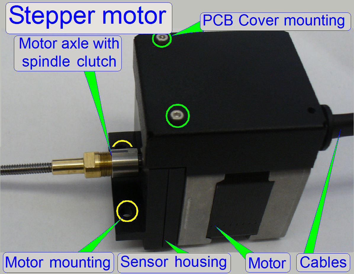
![]() ”Stepper motor without control electronics”
mounted
”Stepper motor without control electronics”
mounted
“X-, Y-, Z-, ND- and Flash
controller”
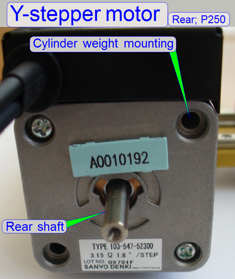
On the rear of the Y-stepper
motor the cylinder
weights are mounted and on the rear shaft the clean dumper is
situated.
- The
clean dumper as well as the cylinder weights is used to absorb
vibration during the sample scan process.
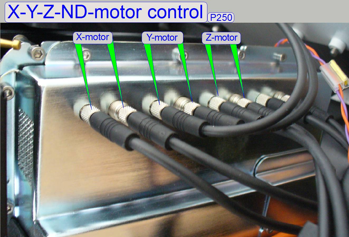 The motor cable
headers are connected at the appropriate position to the control electronics
unit.
The motor cable
headers are connected at the appropriate position to the control electronics
unit.
Important
Please do not use pliers to loosen or tighten the cable header lock
nuts. If there is too much force used on the connector headers, the soldering
of the connector may be destroyed or broken and the appropriate motor will not
work or may working very noisy.
![]() “X-Y-Z-ND-motor and Flash light control electronics” and “Motor cable headers”
“X-Y-Z-ND-motor and Flash light control electronics” and “Motor cable headers”
Even if high scan speeds
should be reached, the elimination or reduce of noise, vibration and resonance
of the stepper motor and its driven mechanics becomes an important aspect.
Therefore, the Y-direction and the X-direction stepper motor was equipped with
appropriate means.
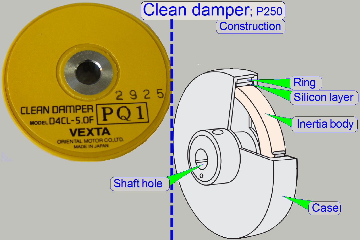
To reduce vibration and
resonance of the Y-stepper motor and so to reduce vibration in Y-direction of
the specimen holder and the slide, the clean damper is mounted by 2 hex key
bolts on the rear shaft of the Y-stepper motor.
Inside the case of the clean
damper the inertia body can move in silicon gel.
The case moves with the same
speed as the rotor of the motor.
During start and stop
operations the inertia body moves with different speed in relation to the case,
absorbs so vibration and creates a stable damping effect.
More information
about vibration of stepper motors can be found in: “Designing for quiet,
vibration-free operation”
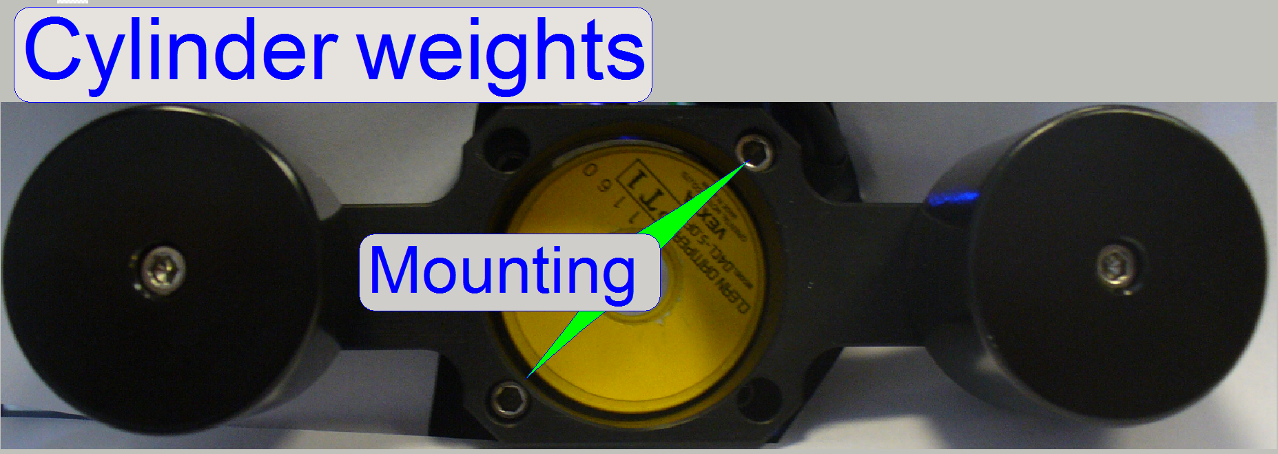 The cylinder weights
are mounted onto the rear of the Y-stepper motor and are used to reduce and
eliminate vibration of the X-carriage (the entire Y-unit) during the scan
process.
The cylinder weights
are mounted onto the rear of the Y-stepper motor and are used to reduce and
eliminate vibration of the X-carriage (the entire Y-unit) during the scan
process.
The carriages are used to
move the specimen holder and so the slide in the X-direction and the
Y-direction.
The dovetail foot is mounted
onto the X-direction mounting plate from beneath and guarantees the proper
mounting and fixing of the entire X-Y-stage unit.
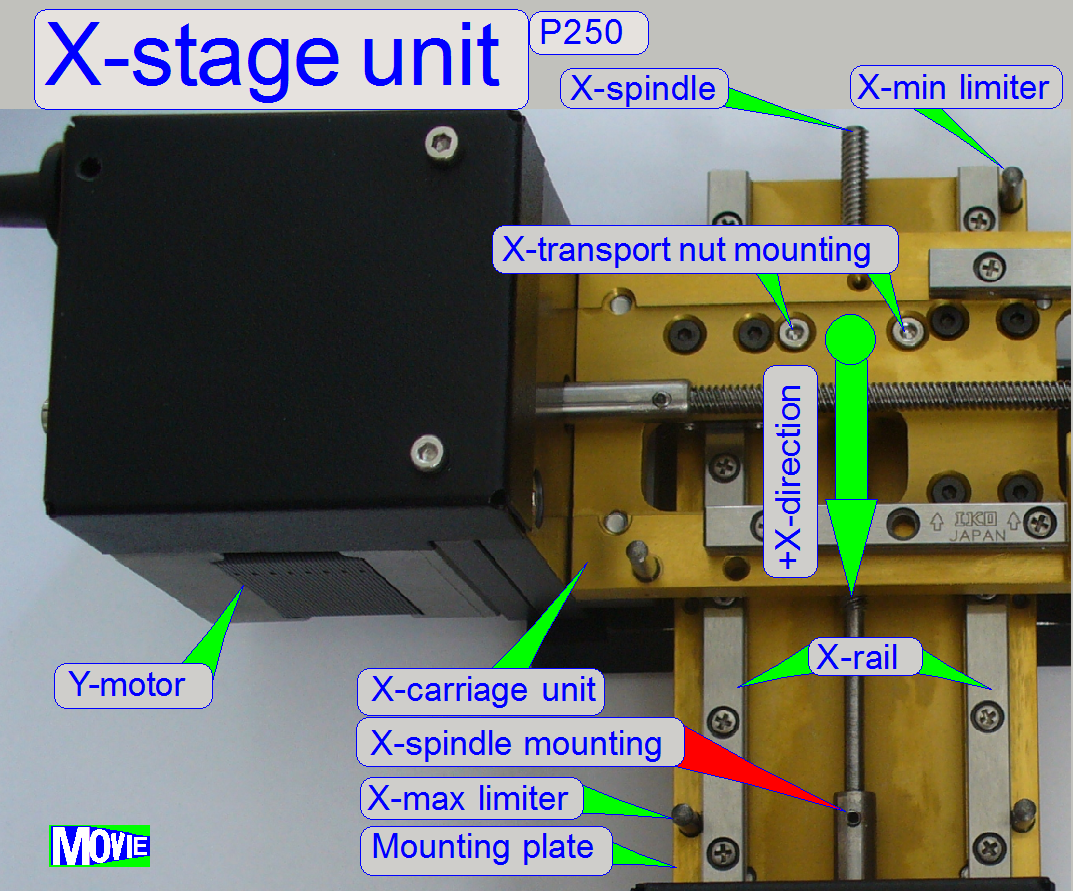 The static part of the
X-stage consists of the following parts:
The static part of the
X-stage consists of the following parts:
- The X-direction mounting plate with the mounted
X-motor, the dovetail foot
(mounted from beneath), the leading rails, the upper and lower limiters.
The dynamic part of the
X-stage consists of:
- X-stepper rotor with spindle and transport nut
- The transport nut is mounted to the Y-stage unit
mounting plate and drives so
- The entire
Y-stage unit.
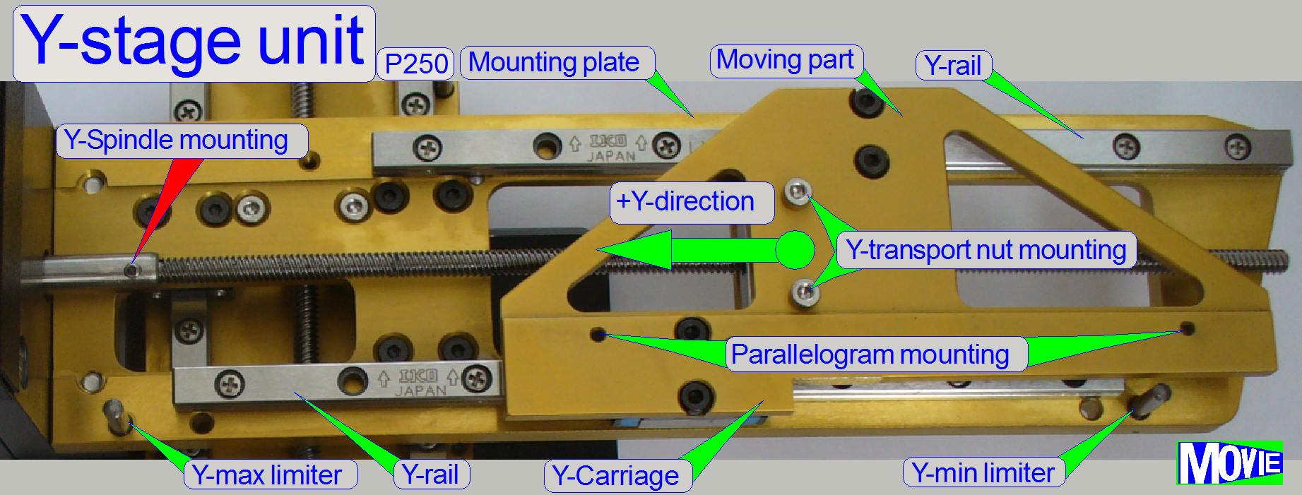 The static part of
the Y-stage consists of the following parts:
The static part of
the Y-stage consists of the following parts:
- The Y-direction mounting plate with the mounted
Y-motor, the leading rails, the upper and lower limiters.
The dynamic part of the
Y-stage consists of:
- The Y-stepper rotor with spindle and transport nut
- The transport nut is mounted to the Y-carriage
and this drives so
- The parallelogram
with the
specimen holder.
The carriages are mounted and
leaded with 2 rails for each direction.
The X and Y rails ensures a
slippage free movement of the carriages in X- and Y- direction. The X-carriage
contains the entire Y-unit. If the motor starts rotating, the spindle drives
the carriage in the direction, defined by the rotating direction of the rotor.
The mechanical dimensioning of the X-Y-stage allows reaching nearly each part
of the slide by the objective, except the barcode area (restrictions are given
by the slide holding mechanics of the specimen holder;
see also the scannable area).
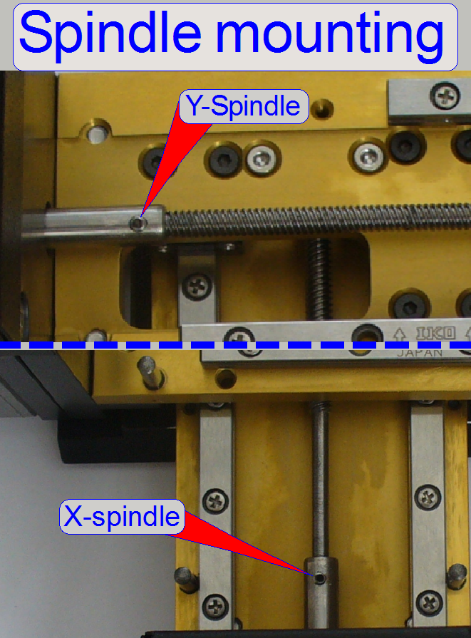
The X- and Y-spindle
respectively are connected directly to the stepper
motor; on the
thread of the spindle the transport nut is situated and the transport nuts are
mounted onto the X- respective Y-carriage.
- To eliminate slippage in the connection between
rotor axle and spindle, the spindles are fixed
with glue and secured by a bolt.
![]() “Spindle mounting” and “Spindle mounting; since
2014”
“Spindle mounting” and “Spindle mounting; since
2014”
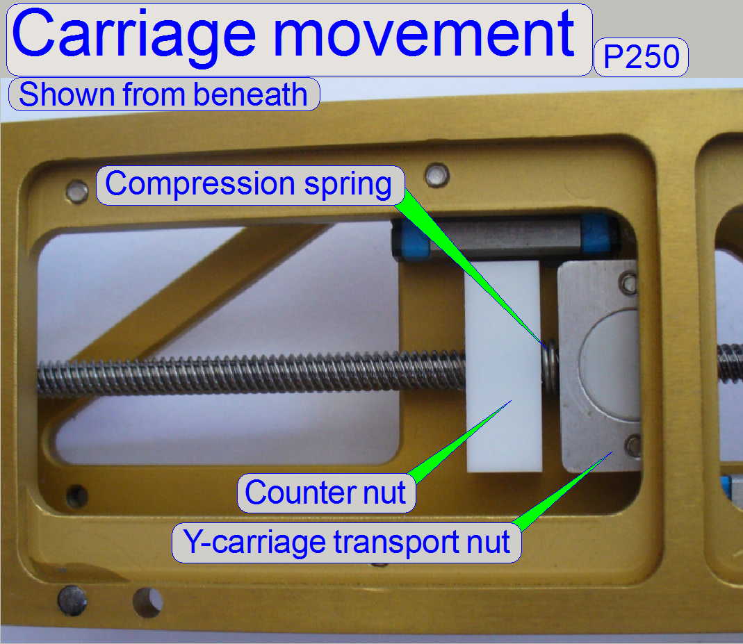
The construction of the carriage transport nuts
ensures a nearly slippage free movement of the carriages, a maximal slip of 4 mm (=4 motor steps) is allowed. The
slippage of the transport nut is minimized by the use of the counter nut and
the compression spring.
The use of the stepper motors
micro stepping mode, combined with the accuracy of the mechanics allows
achieving a resolution of 1mm longitudinal movement per motor step.
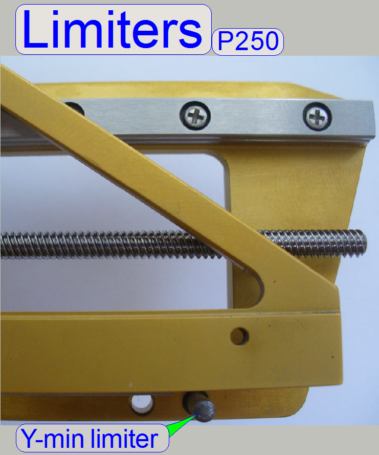 The length of the movement
of each carriage is limited by two limiters, one for the upper and one for the
lower limit, separately for the X- and Y-direction respectively; so the
mechanical construction gets a start and an end position.
The length of the movement
of each carriage is limited by two limiters, one for the upper and one for the
lower limit, separately for the X- and Y-direction respectively; so the
mechanical construction gets a start and an end position.
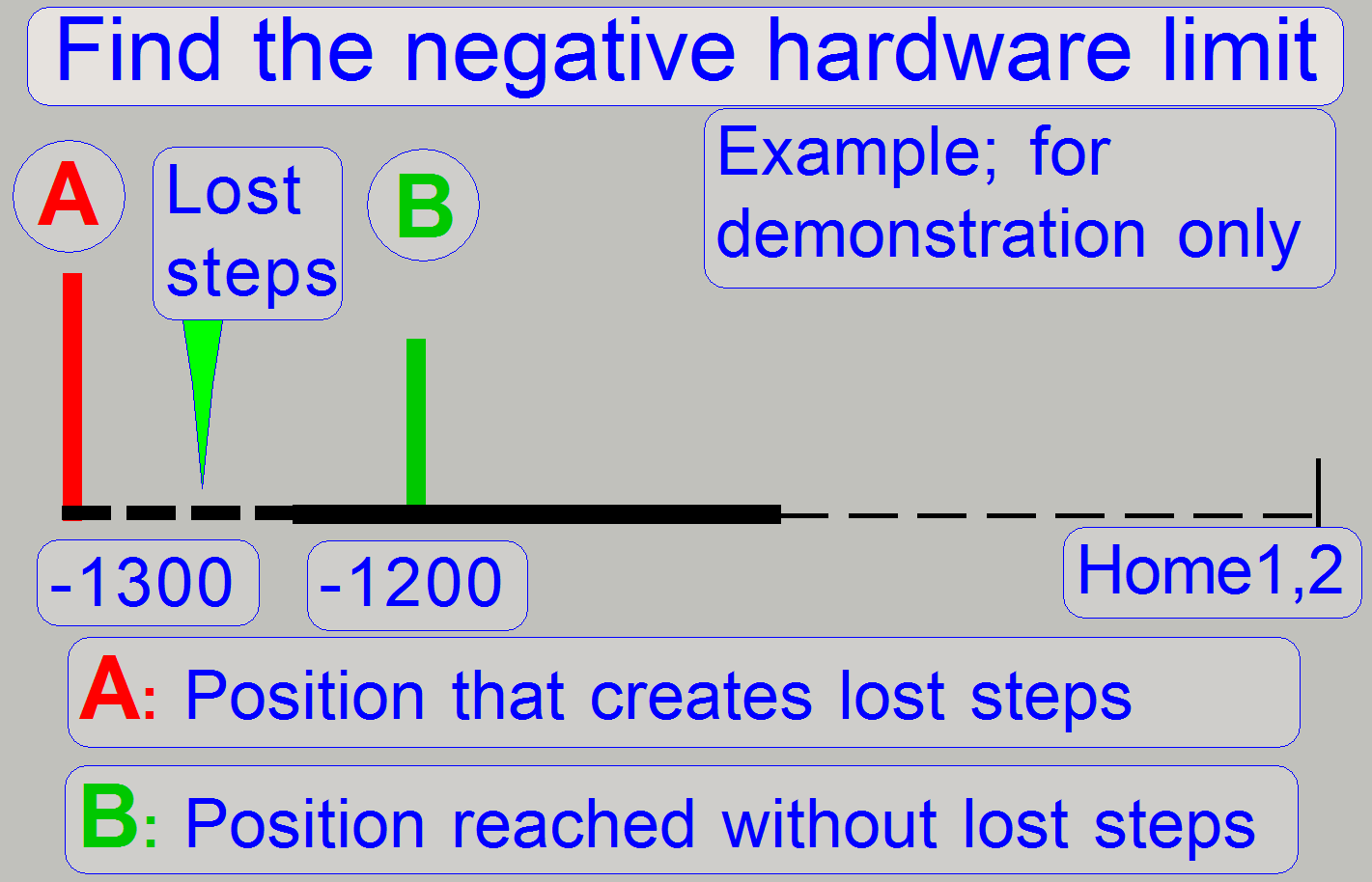
If the mechanical limiter is
reached by the appropriate carriage, the movement stops and, if further steps
have to go, these steps are lost. This behavior creates “lost steps”.
During
the detection of the hardware limits:
Creation of lost steps is used
to find and determine the hardware upper and lower limit. The first number of
steps that do not create lost steps is used as hardware limit; the accuracy is
100 steps (0.1mm).
Example:
· If we found, that
the step number of 1200 steps in negative direction after Home1,2 does create lost steps more than +-2
steps and
· The step number of
1100 steps in negative direction after Home1,2 does not create lost steps (not more than +-2 steps) the negative hardware limit will be -1100
steps.
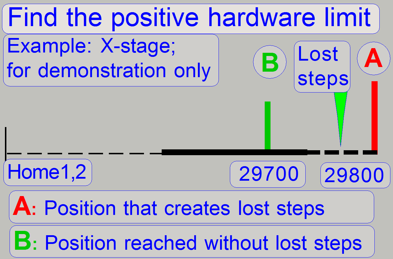
If we are defining the upper
limit, the same principle is used; first we creating lost steps then we
decreasing the number of steps to go by 100 steps until no steps are lost
during the movement.
During
all other actions:
Lost motor steps are unwanted
during slide insert and removal actions and the sample scanning process,
because the counting and reporting of steps mismatches the real number of steps
gone. Therefore, the limits are defined by using the last possible number of
steps without lost steps and an accuracy of 100 steps (=0.1mm) see also later
“Setup procedures”.
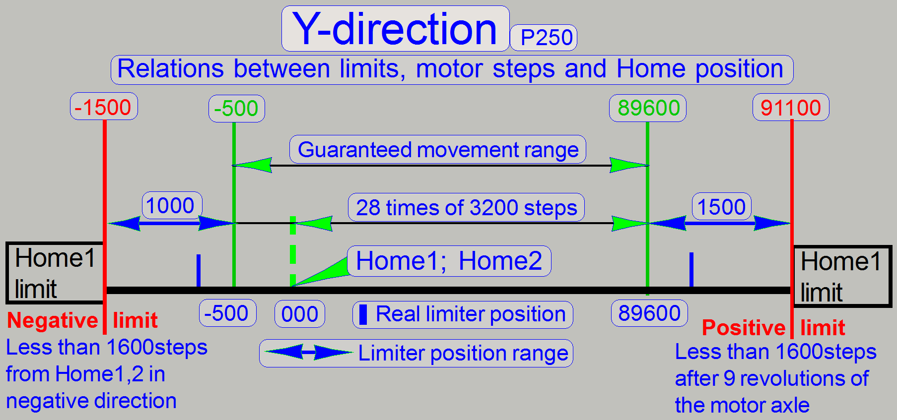
The home position does not
define the mechanical limit. Either in -X- and either in -Y-direction there are
several hundred more steps possible. The theoretical, absolute limits are
defined as shown in the figures “X-direction” and “Y-direction” respectively.
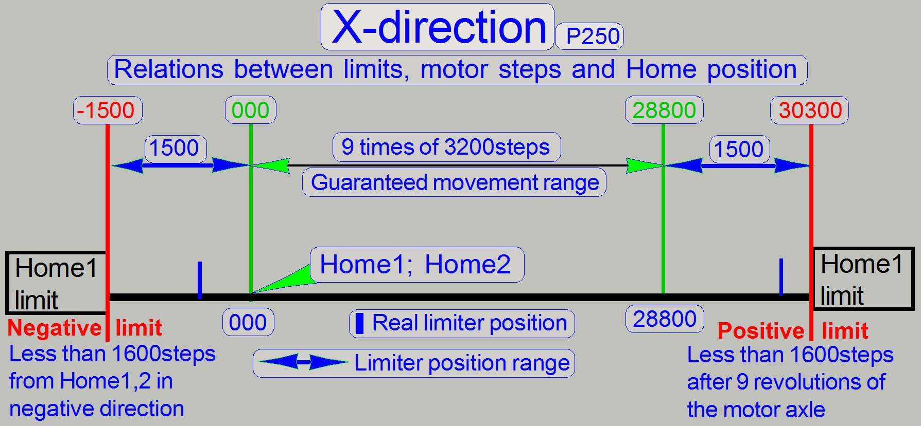
· The unit is
faulty, if there are more than 1600 steps possible in negative direction
without jamming, counted from Home1,2!
· The unit is
faulty, if there are more than 1600 steps possible in positive direction
without jamming after 28800 steps in +X-direction or 89600 steps in
+Y-direction respectively!
The unit should also fulfill the following
requirement:
The negative limit “Y-min”
< -500 steps. This requirement is newer implemented (since October 2012), so
it may be that earlier released versions of the P250 may not fulfill this term.
· In earlier
released P250 scanners, the units will also working correctly; the unit is not
faulty if this requirement is not fulfilled.
![]() “How
to define hardware limits”
“How
to define hardware limits”
The following adjustments are done only, if the motor has to be exchanged,
the X-Y-carriage drive unit was removed or the hysteresis in X- or Y-direction
is too much.
The resolution of the stepper motor by 3200 steps/revolution and
the construction of the spindle together with the transport nut allow a
resolution of 1μm longitudinal movement per motor step; the counter nut
with spring reduces the slippage (resulting in hysteresis) if the rotation
direction changes.
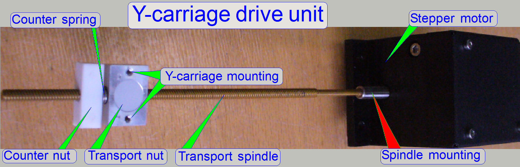
The only difference between the Y-carriage drive unit and the X-
carriage drive unit is the length of the transport spindle; the spindle of the
X-unit is shorter.
 The spindle is
glued into the motor axle and fixed with a
The spindle is
glued into the motor axle and fixed with a
![]() “Spindle mounting
previous solution”
“Spindle mounting
previous solution”
Spindle
mounting; since
2014
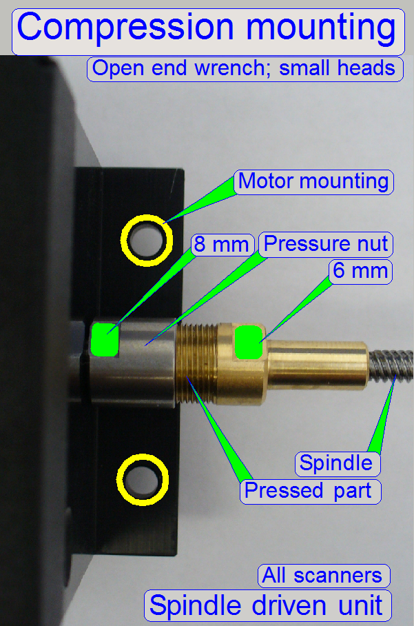 In newer delivered
scanners (since spring 2014) the spindle is mounted to the motor axle by using a
compression mounting; this guarantees also a slippage free connection and the
spindle can be dismounted from the motor axle.
In newer delivered
scanners (since spring 2014) the spindle is mounted to the motor axle by using a
compression mounting; this guarantees also a slippage free connection and the
spindle can be dismounted from the motor axle.
This mounting construction guarantees also a centered mounting of the
spindle.
· The pressure nut
can be rotated with a small head 8mm open end wrench, the pressed part can be
hold with a small head 6mm open end wrench!
· 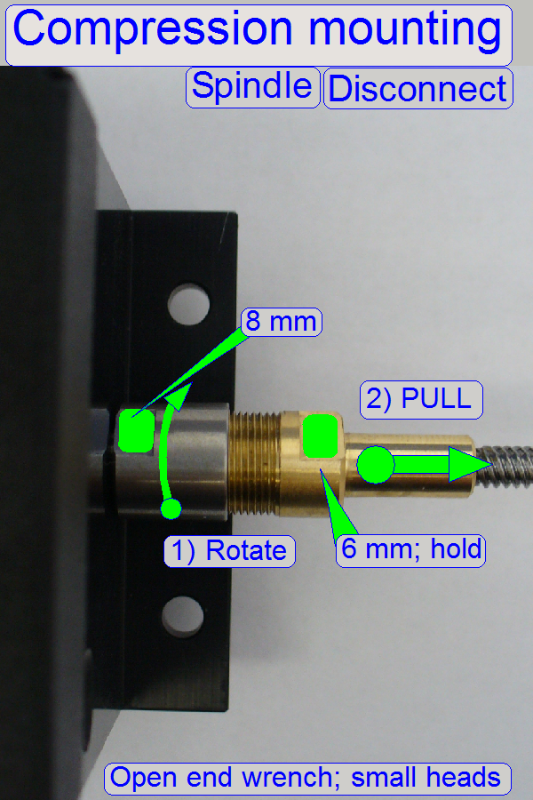 Loosen the
pressure nut and pull the pressed part from the rotor axle.
Loosen the
pressure nut and pull the pressed part from the rotor axle.
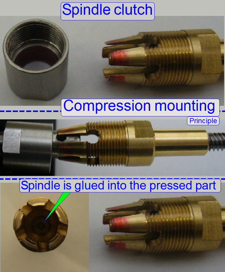 The claws of the pressed
part are fitting the diameter of the rotor axle; the spindle is glued into the
pressed part.
The claws of the pressed
part are fitting the diameter of the rotor axle; the spindle is glued into the
pressed part.
Assemble
the connection
· 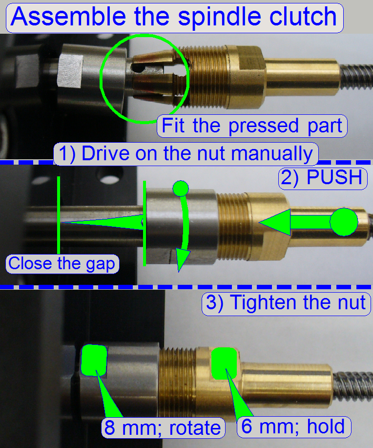 Put the pressure
nut in the right direction onto the motor axle.
Put the pressure
nut in the right direction onto the motor axle.
· Fit the claws onto
the rotor axle.
· Drive the pressure
nut onto the pressed part manually, until it stops.
· Push the pressed
part on the rotor axle against the motor housing until it stops.
· Hold the pressed
part with the 6mm wrench and drive the pressure nut with the 8mm wrench.
· The connection is
correct, if the pressed part is hold on the rotor axle and the gap between
pressure nut and motor housing is not more then 1mm.
· 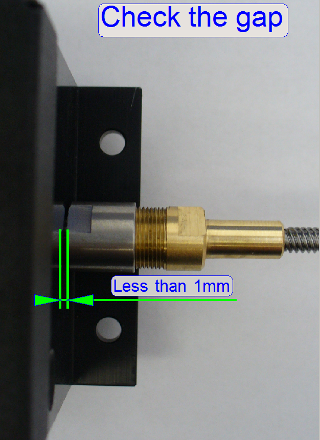 The gap between
the pressure nut and the motor mounting must not exceed 1mm!
The gap between
the pressure nut and the motor mounting must not exceed 1mm!
Transport
spindle; Multi (4) thread
spindle
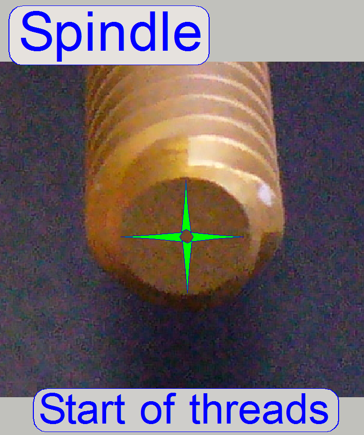
The spindle (together with the transport nut) is used to transform
rotation into slippage free longitudinal movements. The four threads on the spindle
guarantee a precise movement, increase the torque of the mechanical drive and
help to reduce / eliminate slippage / hysteresis.
Motor slip
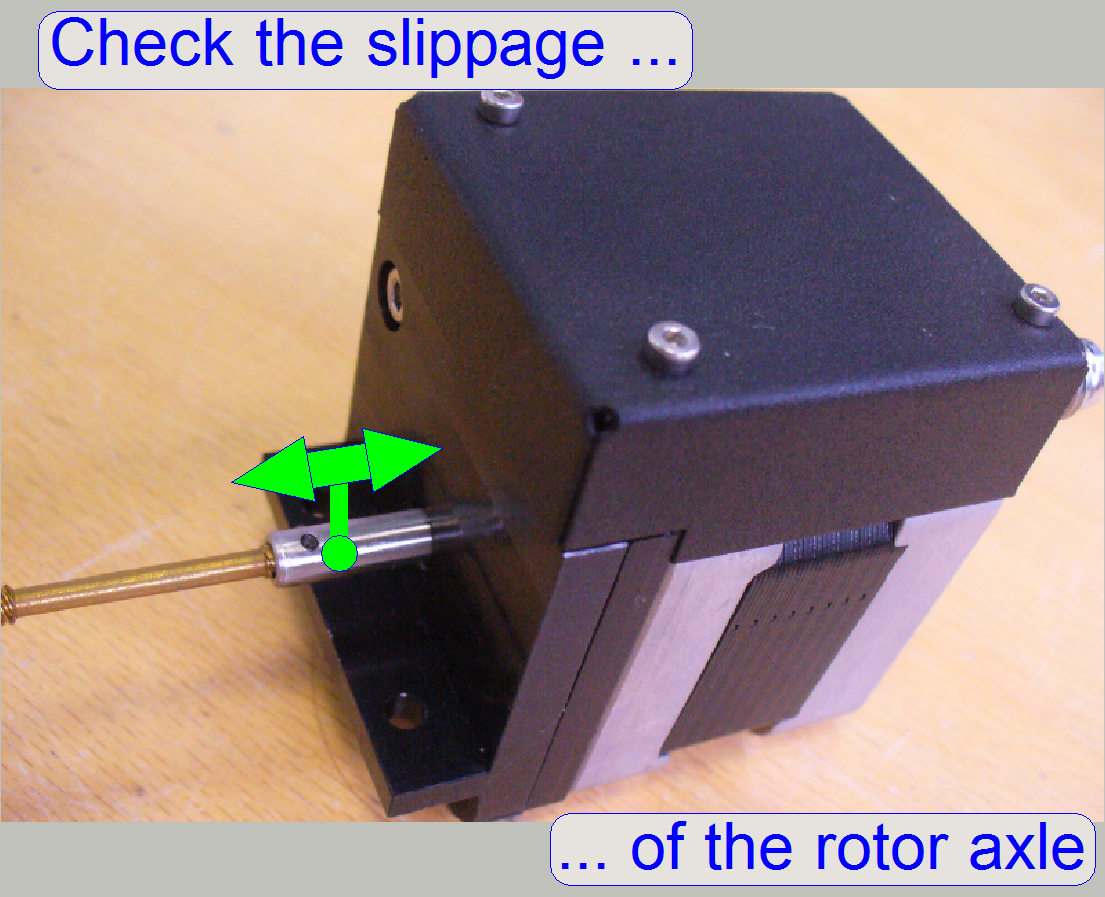 Another important source
of slippage can be the rotor bearing of the motor. Because the rotor has
longitudinal load also, the position of the ball bearings of the rotor must not
change if the rotation direction is changed.
Another important source
of slippage can be the rotor bearing of the motor. Because the rotor has
longitudinal load also, the position of the ball bearings of the rotor must not
change if the rotation direction is changed.
· The motor axle
must not have slippage.
To check the slippage of the motor axle manually, use a force of about 3
N. There have no movement to be expired. Take into account, that a slip of
Eliminate the slippage of the rotor axle
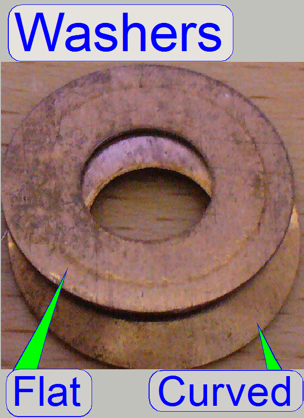 Originally, the rotor
bearing has a spring to eliminate the slip, but the force of the original
spring is often not enough; even if the motor axle has a longitudinal load like
in the X- or Y-carriage. Therefore the original solution was exchanged by using
a flat and a curved washer; the curved washer acts as a spring.
Originally, the rotor
bearing has a spring to eliminate the slip, but the force of the original
spring is often not enough; even if the motor axle has a longitudinal load like
in the X- or Y-carriage. Therefore the original solution was exchanged by using
a flat and a curved washer; the curved washer acts as a spring.
If both washers are inserted well, the slip has to be eliminated.
1.
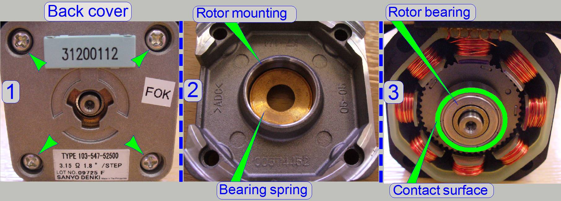 Remove the cover
mounting bolts of the motor (1).
Remove the cover
mounting bolts of the motor (1).
2.
Pull the back cover carefully backward and put it onto
the table as shown (2).
3.
Insert the flat washer first; then the curved washer
so, that its perimeter contacts the rotor bearing as shown (3).
4.
Fit the back cover to the motor and take care of the
washers, they should not falling out.
5.
Drive in the mounting bolts of the back cover; check
the easily movement and the fitting of the rotor, then tighten the mounting
bolts and check the easily movement of the rotor again by hand.
6.
Check the correct movement of the motor with the
service program and listen the sound also; rotate the motor by more ten
revolutions forward and backward some times.
7.
If there can be a sliding or sanding sound listened or
the motor moves strong, loosen the mounting bolts again a little bit and fit
the rotor mounting more precise.
 A following source
of slippage can be the spindle mounting to the rotor axle. The spindle is glued
into the motor axle and fixed with a
A following source
of slippage can be the spindle mounting to the rotor axle. The spindle is glued
into the motor axle and fixed with a
Check the slippage free connection
· Fix the rotor with
one hand and try to rotate the spindle with the other hand, forward / backward.
· Check the
connection also by pushing or pulling the spindle, movements should not be
expired.
· The connection is
faulty if any movement can be expired.
Disconnect
the spindle
·
Remove the worm bolt by using a
·
Heat up the spindle mounting until approx.
300º C and
·
Pull out the spindle from the motor axle and remove
glue residues from the spindle shaft.
Mount
the spindle
·
Put some drops LOCTITE 603 glue onto the spindle
shaft.
·
Insert the spindle shaft into the motor axle’s
drilling.
·
Insert and tighten the worm bolt.
·
Remove unused LOCTITE glue from the spindle
shaft and the motor axle.
·
Check and correct the center of the connection; if the
motor rotates, the spindle end should stay nearly in the center; minimize the
elongation of the spindle end during rotation.
·
The LOCTITE glue should dry up 24 hours before the use
of the carriage drive unit.
Transport-
and counter nut with spring
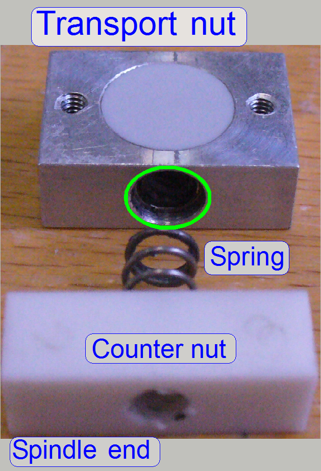 The transport nut
transforms the rotation of the spindle into a longitudinal movement of the
connected peripheral; it moves the Y-carriage to the desired position.
The transport nut
transforms the rotation of the spindle into a longitudinal movement of the
connected peripheral; it moves the Y-carriage to the desired position.
The thread of the spindle and the nut moves the peripheral by
To reach the appropriate limits of the mechanical drive, the position of
the transport nut on the spindle is important; the position can be defined with
an accuracy of a ¼ full turn (because there are 4 threads), it means 800
motor steps.
The limits have to be less than 1600 steps in negative direction counted
from Home1,2 and less than 1600 steps after 28 full turns of the spindle (if
Y-carriage); see also “Hardware
limits” and “Find
the hardware limits for the Y-carriage”; both limits have to be fulfilled
if the adjustment is finished; otherwise dismount the carriage
drive unit, define the position of the transport nut in relation to the
spindle with +- ¼ full turn, mount the carriage
drive unit and check the limits again.
 To eliminate the
slip of the mechanical drive (to reduce and eliminate the hysteresis), the
spring forces the transport nut away from the counter nut. The force of the
spring guarantees the appropriate pressure of the transport nut against the
threads of the spindle. By using the appropriate start point of the threads,
the counter nut can be positioned in relation to the transport nut in the same
way as the transport nut; the position can be defined by a ¼ revolution
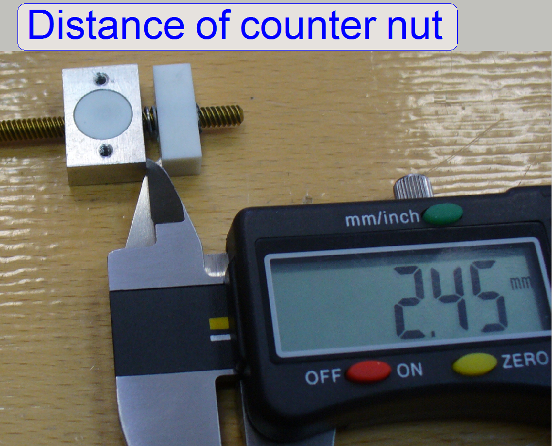
(because there are 4 threads), it means 800 motor steps. The force of the
spring and the position of the counter nut are correct, if the counter nut is
less than or maximal 0.5 turn in distance from the transport nut with fully
compressed spring and the slip (checked after
assembly; with the SlideScanner program) is less than or equal to 4 motor steps
for the Y-carriage; or less than or equal to 8 motor steps for the X-carriage
when the rotation direction of the spindle had changed.
To eliminate the
slip of the mechanical drive (to reduce and eliminate the hysteresis), the
spring forces the transport nut away from the counter nut. The force of the
spring guarantees the appropriate pressure of the transport nut against the
threads of the spindle. By using the appropriate start point of the threads,
the counter nut can be positioned in relation to the transport nut in the same
way as the transport nut; the position can be defined by a ¼ revolution
(because there are 4 threads), it means 800 motor steps. The force of the
spring and the position of the counter nut are correct, if the counter nut is
less than or maximal 0.5 turn in distance from the transport nut with fully
compressed spring and the slip (checked after
assembly; with the SlideScanner program) is less than or equal to 4 motor steps
for the Y-carriage; or less than or equal to 8 motor steps for the X-carriage
when the rotation direction of the spindle had changed.
If the spring can not act, (the counter nut is pressing the transport nut
without a spring acting distance) the drive does not move or is moving too
strong. See also “To check the
maximal hysteresis in Y-direction” and “Optics and illumination”, “Stitching”. If the hysteresis
is too much, reduce it by reducing the distance between transport nut and
counter nut; check also the slip of the motor axle and other drive connections,
see above.
![]() How to exchange the P250_Y_drive_unit
How to exchange the P250_Y_drive_unit
Important
 The parallelogram
must not be adjusted in the field, there are no adjustable parts. The mounting
bolts of the parallelogram and the X-Y-plane adjustment bolt are adjusted; the
necessary adjustment tools are not available in the field. Please do not drive
them!
The parallelogram
must not be adjusted in the field, there are no adjustable parts. The mounting
bolts of the parallelogram and the X-Y-plane adjustment bolt are adjusted; the
necessary adjustment tools are not available in the field. Please do not drive
them!
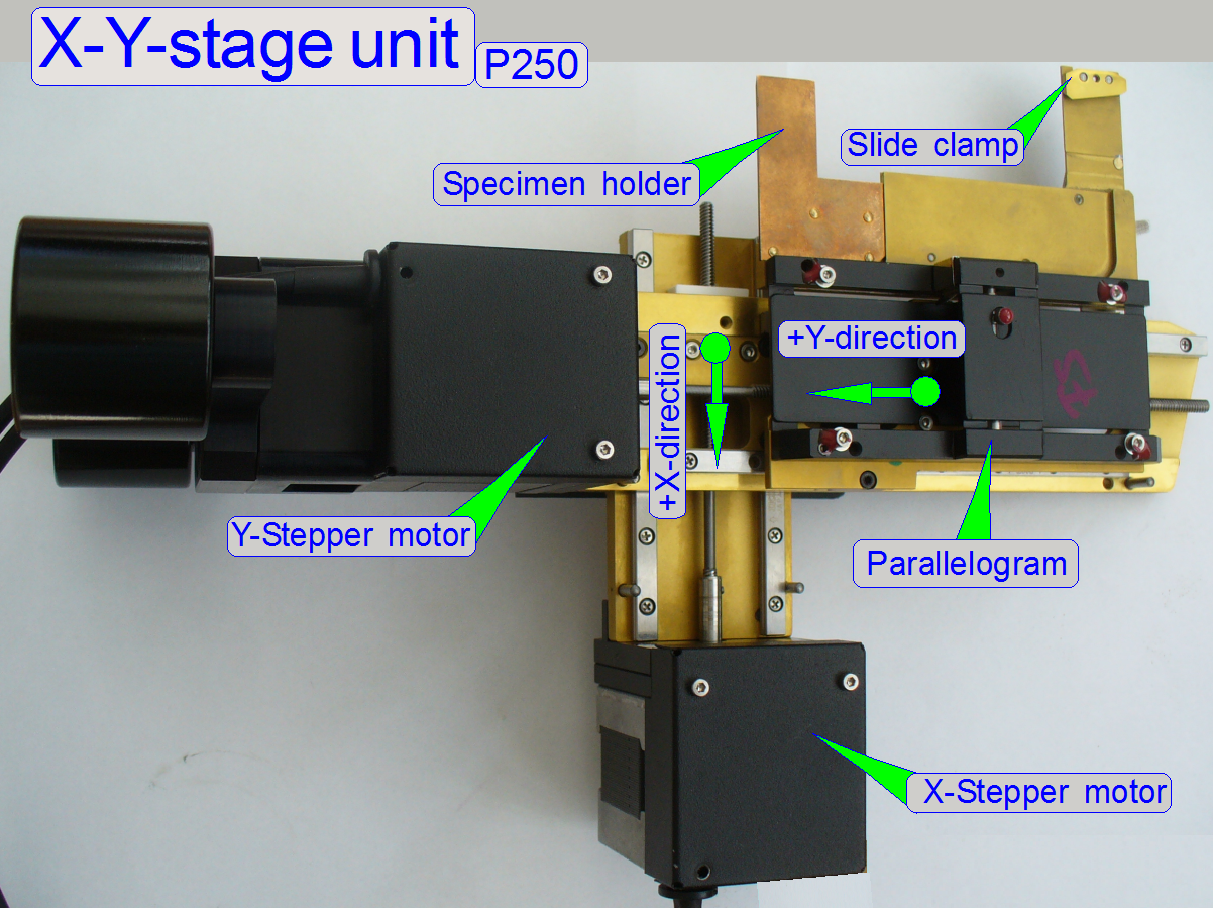
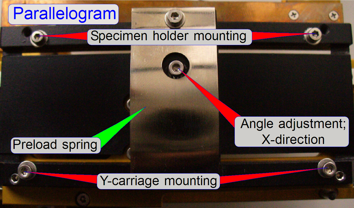
The parallelogram allows the
shifting of the X-Y-plane in Z-direction for focusing the FOV without rotating
the X-Y-plane. On one side of the parallelogram the Y-carriage is mounted; on
the other side the parallelogram holds the specimen holder.
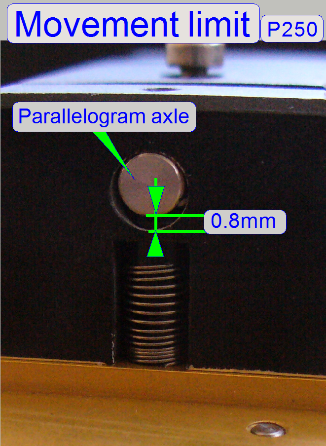
The limiter is constant 0.8mm
and so the maximal movement of the parallelogram is limited.
- The entire parallelogram and the
specimen holder are very sensitive components, because these
guarantee the X-Y-plane in relation to the objective.
Remark Do not adjust the parallelogram in the field, if
possible.
Watch slide show: Parallelogram
![]() How to adjust the parallelogram
How to adjust the parallelogram
 The parallelogram
is not a separate changeable spare part, therefore, the X-Y-Stage or the entire
scanner unit must be changed if there is an irresolvable fault on the
parallelogram.
The parallelogram
is not a separate changeable spare part, therefore, the X-Y-Stage or the entire
scanner unit must be changed if there is an irresolvable fault on the
parallelogram.
- The movement of the parallelogram is limited to
be 0.8mm in the P250 because the movement range of the focus pin had
changed in relation to the PSCAN150.
![]() How to adjust the parallelogram
How to adjust the parallelogram
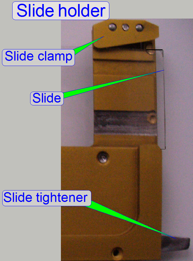
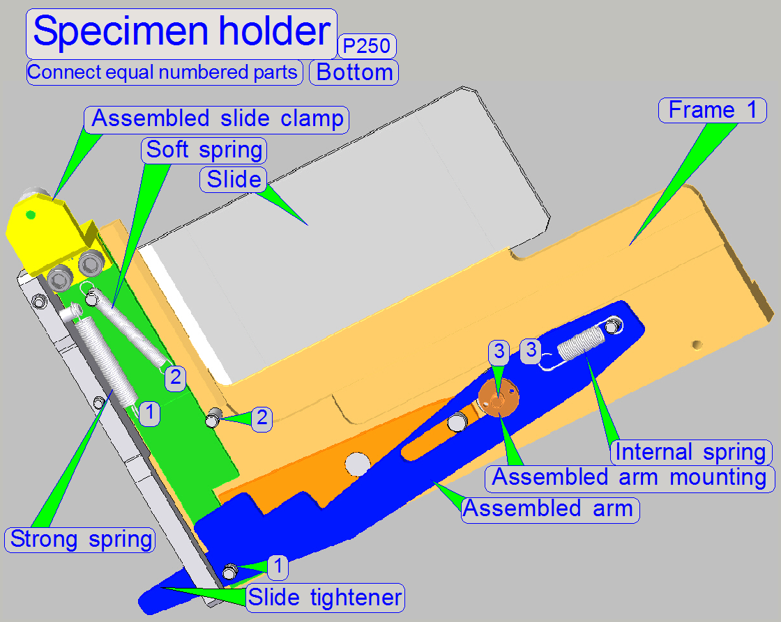
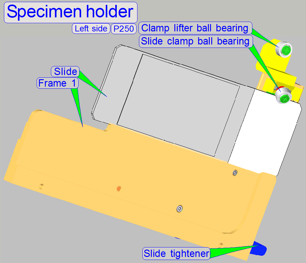
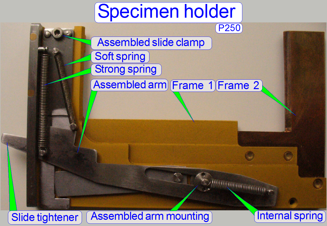 This specimen holder
is designed to hold the slide,
to secure it during scan operation and allows an automatic slide exchange
operation. To loosen the slide during insert / remove, the slide tightener
opens the slide clamp. If the Y-stage is in Home1,2 position, or only some 100
steps away from it and the X-Y-stage moves upward (-X-direction), the slide
tightener contacts the magazine unit (the
specimen holder fixing fork) from below, the slide tightener moves downward
and stretches so the „Strong spring”; the slide is then hold only by the soft
spring.
This specimen holder
is designed to hold the slide,
to secure it during scan operation and allows an automatic slide exchange
operation. To loosen the slide during insert / remove, the slide tightener
opens the slide clamp. If the Y-stage is in Home1,2 position, or only some 100
steps away from it and the X-Y-stage moves upward (-X-direction), the slide
tightener contacts the magazine unit (the
specimen holder fixing fork) from below, the slide tightener moves downward
and stretches so the „Strong spring”; the slide is then hold only by the soft
spring.
Frame2
During slide insert and
removal actions the focus pin fits the Z-position by the help of the frame2.
The Z-position during slide
insert and removal is:
·
In the SCAN: 800steps
(Service program)
·
In the P250: -300
steps (Service program).
![]() “Focusing algorithm” and “Focus range”
“Focusing algorithm” and “Focus range”
 During
the insert or remove slide
operation, the mechanics, driven by the „Assembled arm” loosens the „Assembled
clamp” via the “inverter” mechanics and only the force of the „Soft spring”
holds the slide in the frame. Now, because the force of the “Soft spring” is
not much, the slide can be inserted or removed easily by the slide loader.
During
the insert or remove slide
operation, the mechanics, driven by the „Assembled arm” loosens the „Assembled
clamp” via the “inverter” mechanics and only the force of the „Soft spring”
holds the slide in the frame. Now, because the force of the “Soft spring” is
not much, the slide can be inserted or removed easily by the slide loader.
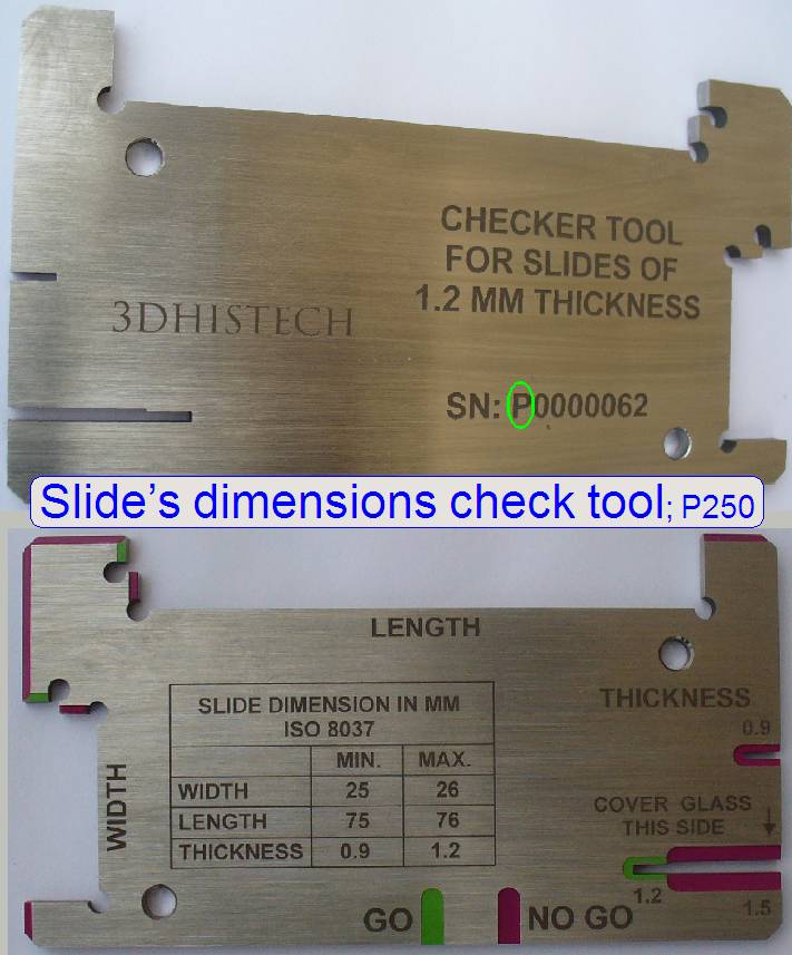
The allowed slide dimensions are:
Length: 75.00 to 76.00mm
Width: 25.00 to
26.00mm
Thickness: 00.95 to 01.20mm
·
Please do not exceed the allowed slide dimensions;
otherwise, the slide clamp may be damaged!
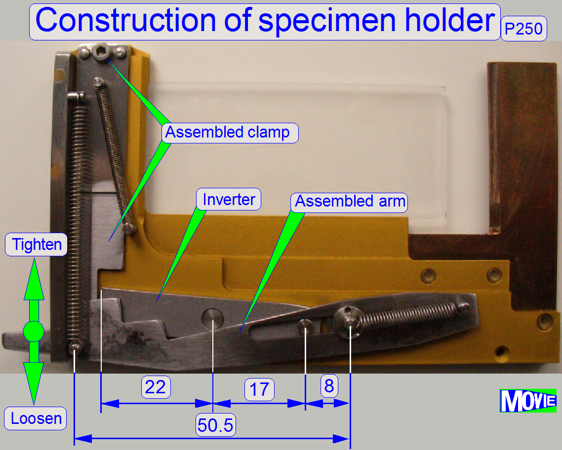 During scanning, the slide is tightened more,
to ensure, that the slide does not change its position in the frame; the force
of the „Strong spring” is 2N ±0.5N. Via the „Assembled arm” and the
„Inverter”, the „Strong spring” forces the „Assembled clamp” downward in
relation 50.5:8 (the “Assembled arm” amplifies the force of „Strong spring”)
and in relation 17:22 the „Inverter” attenuates a little bit this force, but
its main task is, to invert the movement. This way the force of the slide clamp
is nearly 5 times stronger than the force of the “Strong spring”.
During scanning, the slide is tightened more,
to ensure, that the slide does not change its position in the frame; the force
of the „Strong spring” is 2N ±0.5N. Via the „Assembled arm” and the
„Inverter”, the „Strong spring” forces the „Assembled clamp” downward in
relation 50.5:8 (the “Assembled arm” amplifies the force of „Strong spring”)
and in relation 17:22 the „Inverter” attenuates a little bit this force, but
its main task is, to invert the movement. This way the force of the slide clamp
is nearly 5 times stronger than the force of the “Strong spring”.
The „Internal spring” forces
the „Assembled arm” (and so the slide tightener also) always in its right
position, even if there was an unwanted collision with the magazine unit (this
works only, if there is no slide present in the specimen holder).
- Do not use
grease or oil on any part of the specimen holder!
- Keep the
specimen holder mechanics clean; dust, glass shards or paraffin residues
on any part may prevent the specimen holder mechanics from correct
working!
Watch
Video: “Slide
clamp and slide tightener”
· 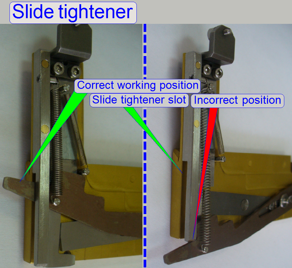 Please check the
correct slide tightener’s position in its slot, if the X-Y-Stage unit was
inserted and also, if the slide was inserted or removed manually!
Please check the
correct slide tightener’s position in its slot, if the X-Y-Stage unit was
inserted and also, if the slide was inserted or removed manually!
![]() “Insert or remove the
slide manually”
“Insert or remove the
slide manually”
Watch video: Slide tightener_P250
 In newer solutions
of the specimen holder, the Frame2 is removed; its task is fulfilled by the
“Specimen holder fixing fork”. The correct position of the specimen holder
during slide insert and removal is defined by positioning the “Specimen holder
fixing fork”.
In newer solutions
of the specimen holder, the Frame2 is removed; its task is fulfilled by the
“Specimen holder fixing fork”. The correct position of the specimen holder
during slide insert and removal is defined by positioning the “Specimen holder
fixing fork”.
![]() “Specimen holder fixing
fork”
and “Adjust
the magazine unit position”
“Specimen holder fixing
fork”
and “Adjust
the magazine unit position”
Battered and damaged slide clamp
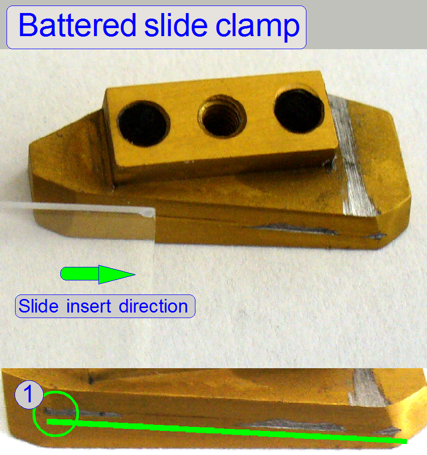 A battered slide
clamp may cause some unwanted occurrences during slide loading, focusing and
other slide or tissue handling actions.
A battered slide
clamp may cause some unwanted occurrences during slide loading, focusing and
other slide or tissue handling actions.
Occurrence
The shown slide clamp does
not allow the insertion of brand new slides during the slide insert action.
The edge (3)
of the inner finger even released the slide clamp and now, the slide inner
edge should more open the slide clamp.
Because a step was engraved
during previously loaded slides (see (1); on the right), the slide insert
action was stopped and aborted; the loading procedure of following slides was
very instable; even if the shortest
slides are loaded.
Cause
- Probably the value of the parameter “SlideInsertPositionX”
was defined wrong (the specimen holder stays to much down during insertion
of the widest slide) and so the edges of the slides engraved a step into
the slide holding surface of the otherwise smooth slide clamp surface or
- The height of the inner finger is
incorrect; the inner finger stays to much down and so the slide clamp
stays not open enough during slide insertion of the
widest and thickest allowed slides or
- The loaded slide dimensions exceeded the
allowed slide dimensions or
- A combination of the named events.
Solution
Adjust the slide insert
positions and the
height of the inner finger more precise and exchange the slide clamp.
Slide clamp with ball
bearings
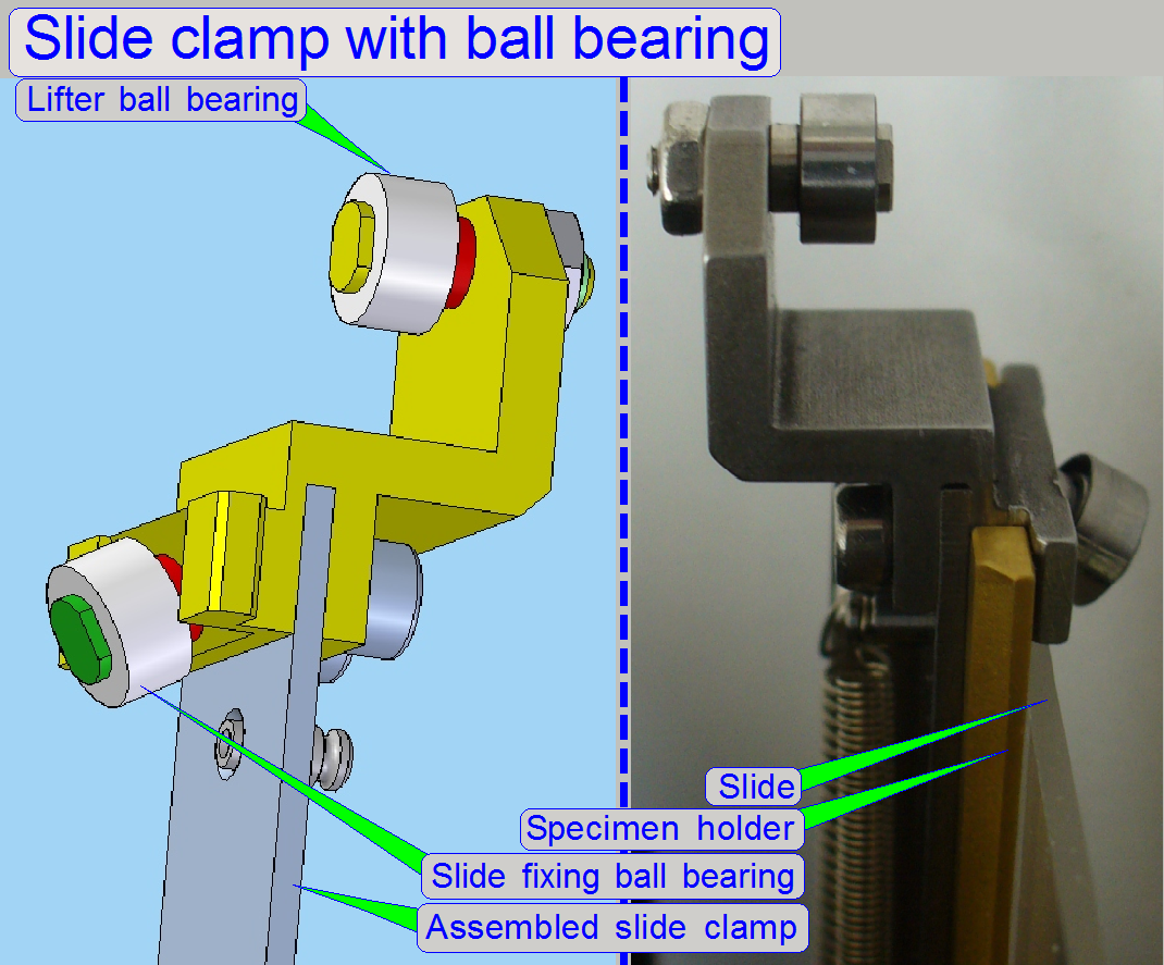 The construction of
the slide clamp is modified since October 2012 and increases the safeness of
the used components.
The construction of
the slide clamp is modified since October 2012 and increases the safeness of
the used components.
- The slide edge, during slide insertion and
removal is now moving on the surface of the “slide fixing ball bearing”
this surface is pressed with the force of the “soft spring” against the
slide edge. The inclination angle of the “Slide fixing ball bearing”
allows an easy handling of different slide
thicknesses during slide insertion and slide removal; furthermore, the
slide is correctly fixed during slide scanning by using the amplified
force of the “Strong spring”; see above.
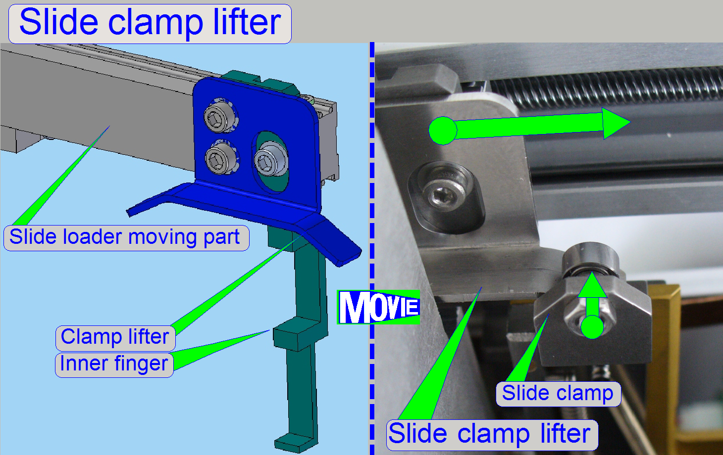
- The “Slide
clamp lifter ball bearing” moves on the runway of the “slide clamp lifter”
with a very small mechanical resistance and, defined by the shape of the
runway of the clamp lifter, it lifts up the slide clamp until the first
part (the inner edge) of the slide is fully inserted and then it lowers
down the slide clamp again; remember, the slide may differ in length; see
also: Slide
dimensions.
and “Adjust
slide clamp lifter position”
Watch video: Slide clamp
lifter_P250
Adjustments for the X-Y-carriage unit
The following procedures are
described for the Pannoramic 250 and based on the service program version 1.15.
Find the hardware limits for the X-carriage
This procedure must be done only
if the scanner unit or the X-Y-stage was changed.
This procedure has to be done
if the drive unit for the X-direction was exchanged.
·
Insert
a medium
large slide and set the focus motor to -300 steps.
Find the negative
limit in -X-direction
1.
With the service program set the Y-carriage to
Home1,2.
2.
Set the X-carriage to Home1,2.
3.
With the service program go forward to the X-motor
position -1200 steps.
4.
Go backward +1200 steps.
5.
Press Home1 (only). There should be not more than +-2
steps difference to Home1. If there are more steps lost, decrease the actual
absolute number of steps by 100 and repeat from step
6.
If there are not more than 2 steps difference to
Home1, increase the number of steps by 100 and repeat from step
7.
The negative limit is found correctly if the motor
movement has no steps lost and the actual absolute number of steps, increased
by 100 would produce lost steps. The found negative limit can differ by more
100 steps from unit to unit. The reason is the tolerance of the components and
the found thread starting position of the spindle in relation to the transport
nut.
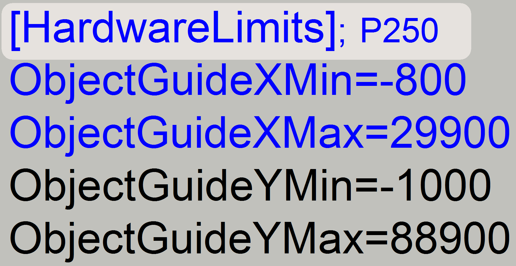
8.
Update the value of the parameter “ObjectGuideXMin” in the file “MicroscopeConfiguration.ini” section [HardwareLimits] with the found
number of the actual steps and save the file.
Find the positive limit in +X-direction
9.
 With the service
program set the X-carriage unit to Home1,2.
With the service
program set the X-carriage unit to Home1,2.
10.
Go forward to the X-motor position +29700 steps.

11.
Go backward 29700 steps.
12.
Press Home1 (only). There should be not more than +-2
steps difference to Home1. If there are more steps lost, decrease the actual
number of steps by 100 and repeat from step
13.
If there are not more than 2 steps difference to
Home1, increase the number of steps by 100 and repeat from step
14.
The positive limit is found correctly if the motor
movement has no steps lost (max. 2 steps) and the actual number of steps,
increased by 100 would produce lost steps. The found positive limit can differ
by more 100 steps from unit to unit. The reason is the tolerance of the
components and the found thread starting position of the spindle in relation to
the transport nut.
15.
Update the value of the parameter “ObjectGuideXMax” in the file “MicroscopeConfiguration.ini” section [HardwareLimits] with the found
value and save the file.
16.
Check the found limits by using the number of steps,
used as parameter value in the file “MicroscopeConfiguration.ini” section [HardwareLimits]. Lost steps have not to occur.
Find the hardware limits
for the Y-carriage
·
 This procedure
must be done only if the scanner unit or the X-Y-stage was changed.
This procedure
must be done only if the scanner unit or the X-Y-stage was changed.
·
This procedure has to be done if the drive unit for
the Y-direction was exchanged.
·
Move the X-carriage +29000 steps from Home1,2; this
way, the slide tightener can not collide with the magazine unit and the focus
pin does not collide with the lower edge of the specimen holder.
Find the negative limit in -Y-direction
Repeat the steps,
described in the procedure above “To find the negative limit in -X-direction” logically
with the Y-carriage.
·
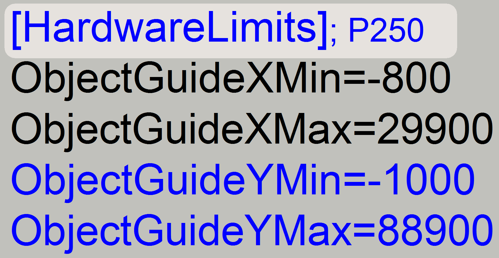
Update the value of the parameter “ObjectGuideYMin” in the file “MicroscopeConfiguration.ini” section [HardwareLimits] with the found
number of the actual steps and save the file.
Find the positive limit in +Y-direction
 The
shown example on the right is used to check the limit of the Y-drive unit; it
can not be used as hardware limit!!
The
shown example on the right is used to check the limit of the Y-drive unit; it
can not be used as hardware limit!!
·
Move the X-carriage +29000 steps from Home1,2; this
way, the slide tightener can not collide with the magazine unit and the focus
pin holder does not collide with the lower edge of the specimen holder.
Repeat the steps,
described in the procedure above “To find the positive limit in +X-direction”
logically with the Y-carriage. The positive limit of the Y-carriage is found
correctly in the near of 90 000 steps or even before the specimen holder
will be touched.
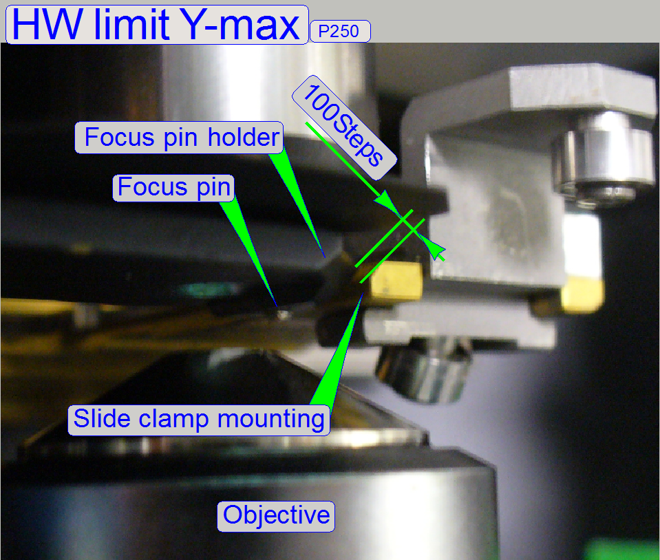
Important!
To avoid
collision of the slide clamp with the focus pin holder, the possible upper
limit of the Y-carriage can not be used as hardware limit!
Important
 The
possible maximal movement limit of the Y-carriage can not be used in the system
as hardware limit because collision of the focus pin holder with the slide
clamp (mounting) would occur.
The
possible maximal movement limit of the Y-carriage can not be used in the system
as hardware limit because collision of the focus pin holder with the slide
clamp (mounting) would occur.
·
Move the X-carriage +29000 steps
from Home1,2; this way, the slide tightener can not collide with the magazine unit
and the focus pin holder does not collide with the lower edge of the specimen
holder.
·
Move the Y-carriage in direction to
the limit “Y-max” until a gap of 0.1mm (= 100 steps) exists between the focus
pin holder and the slide clamp (mounting)!
The value is found in the
near of 89000 steps
·
Update the value of the parameter “ObjectGuideYMax” in the file “MicroscopeConfiguration.ini” section [HardwareLimits] with the found
value and save the file.
Check
the hysteresis in Y-direction
General
 The software divides the sample to be scanned, seen by
the preview camera into fields of views; the size of the FOV depends on the
resolution of the scan camera and the magnification of the camera adapter. Each
field of view contains a small part of the neighbor FOV. In this way, stitching
becomes possible. Because the capturing of the FOV’s is done on a meandering
course, the Y-direction is often changed. If the hysteresis in Y-direction is
too much, stitching will not work correctly; therefore, we have to check the
hysteresis in Y-direction. The maximal allowed hysteresis is 4 μm (=4
motor steps). We comment that this hysteresis decreases itself by some motor
steps after some sample scan procedures, even if the X-Y-stage is brand new.
The software divides the sample to be scanned, seen by
the preview camera into fields of views; the size of the FOV depends on the
resolution of the scan camera and the magnification of the camera adapter. Each
field of view contains a small part of the neighbor FOV. In this way, stitching
becomes possible. Because the capturing of the FOV’s is done on a meandering
course, the Y-direction is often changed. If the hysteresis in Y-direction is
too much, stitching will not work correctly; therefore, we have to check the
hysteresis in Y-direction. The maximal allowed hysteresis is 4 μm (=4
motor steps). We comment that this hysteresis decreases itself by some motor
steps after some sample scan procedures, even if the X-Y-stage is brand new.
Because the X-direction is
never changed during a sample scan process (the direction is always +X), the X-hysteresis
is not critical and can be some steps more (max: 8 steps).
Watch video: Scan a tissue_P250
Check the maximal hysteresis in Y-direction
·
 Start the program “SlideScanner.exe”
with the service password.
Start the program “SlideScanner.exe”
with the service password.
·
In the tab “Focus” produce a sharp life view; adjust
the exposure time and the white balance as required.
·
In the tab “Service” select “Microscope control”.
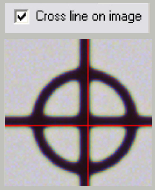
·
Select the option “Cross line on image”.
·
Set a zoom value of about 2,73.
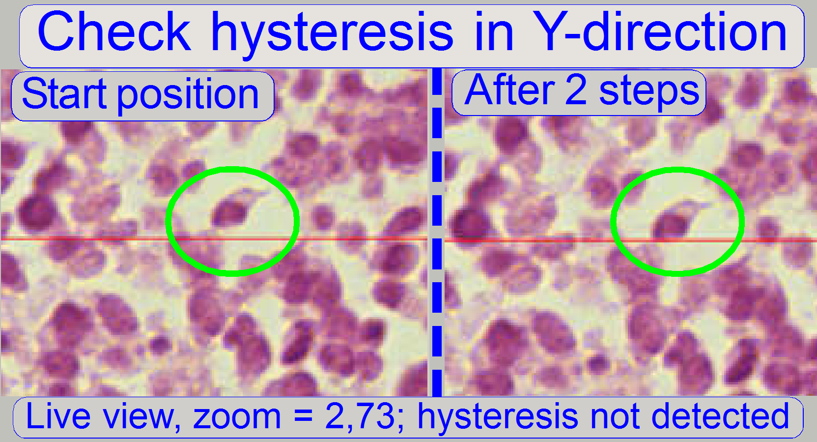
·
In the part of the X-Y-control select a step size of
two steps and go upward (or downward), until the tissue moves.
·
Now go in opposite direction and count the clicks
until the tissue moves. If more than 3 clicks (6 steps) are required, the
hysteresis in Y-direction is too much.
·
If the stage is moved to the left or to the right
respectively, the hysteresis in X-direction can be determined.
Dismount or mount the carriage drive unit
Dismount the carriage drive unit
· Remove the
transport nut mounting bolts from the appropriate carriage.
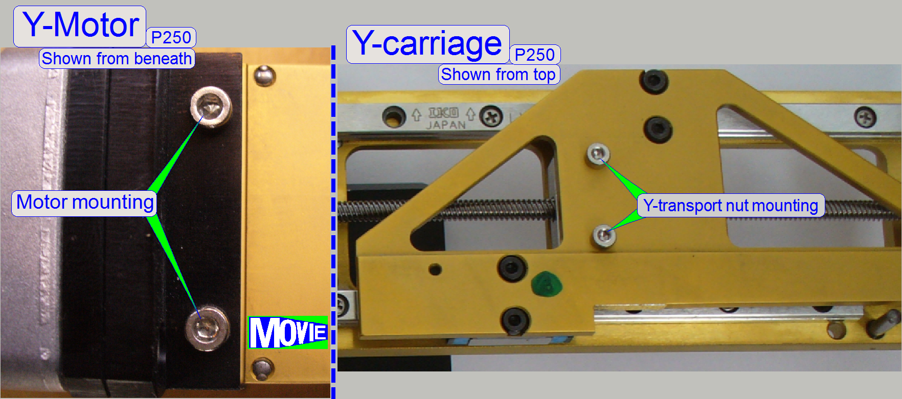 · Remove the motor
mounting bolts.
· Remove the motor
mounting bolts.
· Pull the motor
together with the entire carriage transport unit out of the carriage.
![]() P250_Y_drive_unit_exchange.htm
P250_Y_drive_unit_exchange.htm
1.
Set the motor to Home1,2.
2.
Screw the transport nut onto the spindle some turns.
3.
Insert the carriage drive unit and check the position
of the transport nut in relation to the bolt drillings on the carriage; the
drillings of the carriage should fit the transport nut near to the negative
limit.
4.
Remove the transport unit and adjust the position of
the transport nut in relation to the carriage mounting more precise by using
half turns also.
5.
Set the motor to Home1,2.
6.
Insert the carriage transport unit, drive in the motor
mounting bolts and the transport nut mounting bolts and check the negative
limit; see also above “The limiters” and adjustment procedures “To find the
negative limit”. The negative limit is often found in the near of -800 steps
(but this is not a requirement).
7.
If the negative limit does not fit the requirements
(more than 1600 steps are possible in negative direction) remove the carriage
drive unit again and adjust the position of the transport nut in relation to
the spindle by using the next / previous start point of the thread; this way
the limit can be adjusted with an accuracy of 800 steps (a ¼ revolution)
and this fulfill the requirements always (this is done only, if the adjustment
by using half turns does not deliver the successful result).
8.
Repeat from step 4 until the requirements of the
negative limit are fulfilled.
9.
Check the positive limit; see also “Adjustment procedures”.
10.
By loosening the motor mounting bolts and tighten them
in the correct motor position, the straightness of the drive unit can be found
and adjusted.
Remove
or mount the X-Y-stage unit
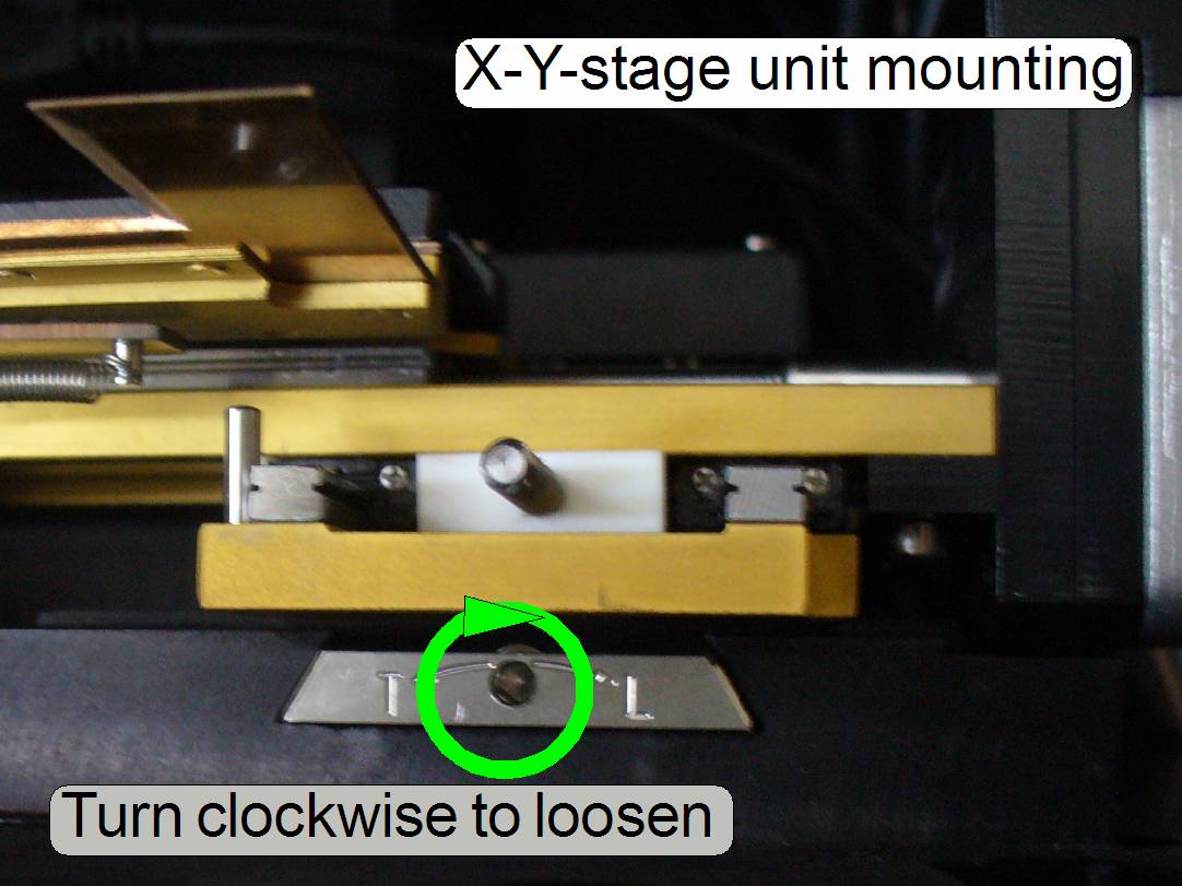
X-Y-stage unit
mounting
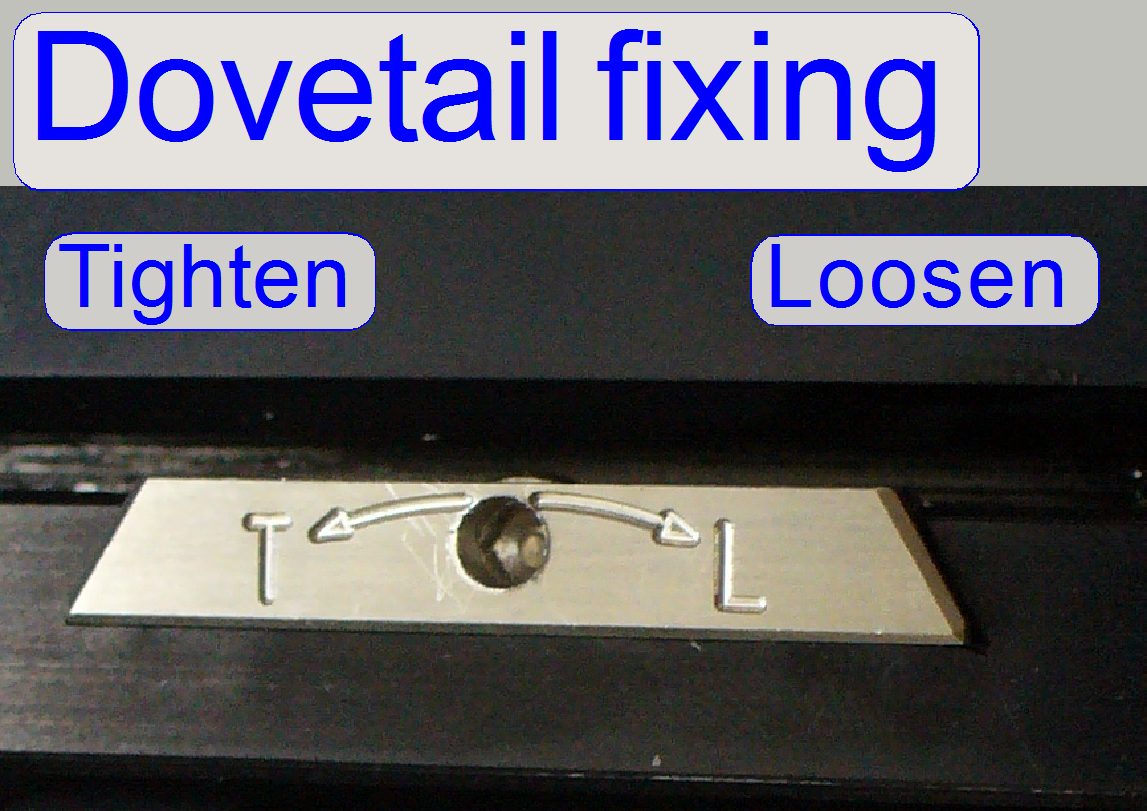
The mounting of the X-Y-stage
unit and the mounting of the focus unit with objective changer are realized
with dovetails; these are hold by dovetail fixing clamps.
- Rotate the 2.5 hex key wrench
clockwise to open (loosen) the dovetail clamp.
Watch Video: Remove focus unit (SCAN)
Remove the X-Y-stage unit
1.
 Move the X-direction to Home1,2
and move the Y-direction to Home1,2.
Move the X-direction to Home1,2
and move the Y-direction to Home1,2.
2.
Then move the X-direction to X=+28 000 steps.
3.
Move the Y-direction to Y=+80 000 steps.
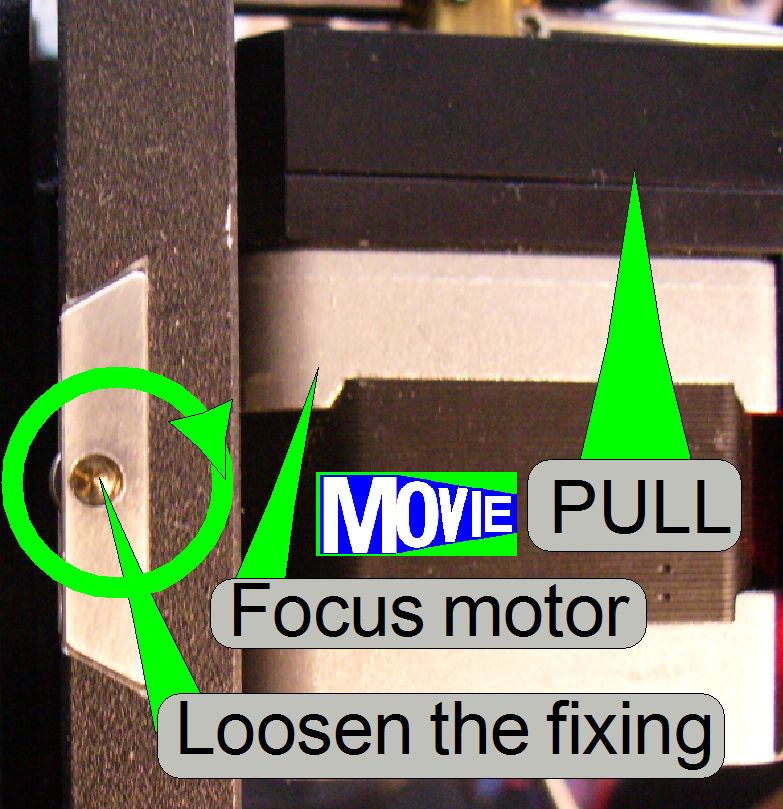
5.
Disconnect the cables, loosen the X-Y-stage unit
fixing bolt and remove the X-Y-stage unit by pulling it backward.
Watch Video: Remove X-Y-Stage unit (SCAN)
Mount the X-Y-stage unit
6.
 Move the X-stage to
the position 28000 steps.
Move the X-stage to
the position 28000 steps.
7.
Insert the X-Y-stage unit until it stops and tighten
the fixing bolt.
9.
Connect the cables of the focus unit, the Y-part
cables and the X-part cables.
10.
Check the position of the slide tightener; it should
release the slide clamp if the Y-direction Homr1,2 and the X-direction Home 1,2
is found.
Watch Video: Mount X-Y-Stage unit (SCAN)