X-Y-stage unit;
S_M_D
For
technicians and sales managers
This section describes the components, functionality, handling,
installation and checking instructions of the X-Y-stage unit for the Pannoramic SCAN,
Contents
Maximal hysteresis in
Y-direction
·
For safety regulations regarding human
health and scanner functionality please refer to: Precautions
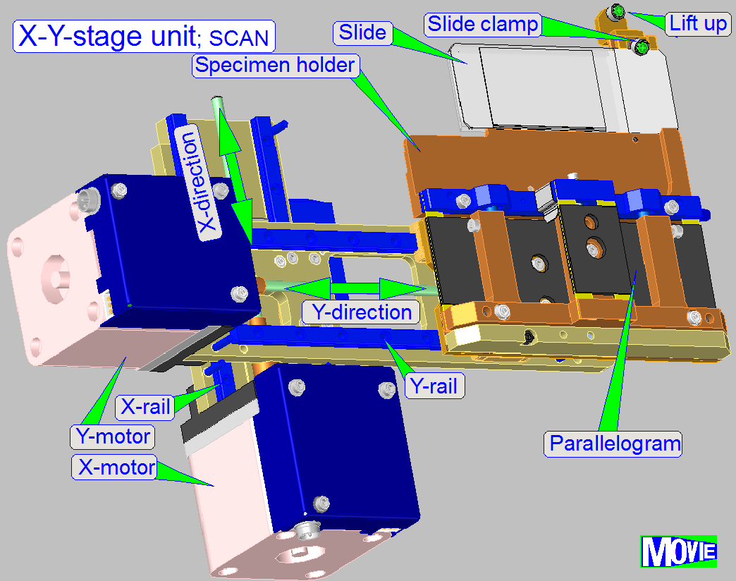
The X-Y-stage unit is used to
position the slide at slide insert and slide remove action. It also moves the
slide in X- and Y-direction during the scan process. Allowed slide dimensions
can be found here. The
movements are realized by stepper motor driven mechanics. The principle of the
slide insertion and specimen holding is different in the three scanners, so the
construction of the specimen holders are also different and will be discussed
separately for each scanner in this description.
The X-Y-stage unit is mounted
with a dovetail mounting, so the correct position is reached again
automatically after the unit was removed and mounted again.
The exchange of the X-Y-stage unit is necessary
- If one of the
stepper
motors or its electronics is faulty.
- If the
maximal allowed hysteresis of 4 steps in Y-direction is exceeded.
Information about the hysteresis can be found here.
- If the shape
of any parts is deformed or a part is broken.
- If the
X-Y-stage unit has any other faults.
- In all cases,
refer first to the chapter “Before you start to replace units”.
Requirements
- Service
program for the slide scanners (“SlideScannerService.exe”)
with the actual license file.
- Slide scanner
and Slide Viewer software (“SlideScanner.exe”,
“SlideViewer.exe”)
with the actual dongle.
- 1.5, 2.5, 3
and
- Hardware and
construction knowledge of the Pannoramic
scanners.
Warning! Do not
mix the versions of “SlideScanner.exe” and “SlideScannerService.exe”.
 Always use these programs with the same
version number, otherwise the “SlideScannerService.exe” program can produce unwanted results, and
the “SlideScanner.exe” will not
work correctly or can freeze.
Always use these programs with the same
version number, otherwise the “SlideScannerService.exe” program can produce unwanted results, and
the “SlideScanner.exe” will not
work correctly or can freeze.
X- and Y-Stage unit
Modifications since summer 2016
- Mounting of the X-Y-stage unit to the scanner
plate was modified, so vibration and noise is reduced
- Using of
5-Phase stepper motors improves smoothness of the rotor’s movement to
reduce vibration
- Using of
improved X-rails increases stability in X-direction
- Newly
designed Y-rail solution increases stability in Y-direction
- Newly
designed spindle mountings allowing simplified, easily adjustments
- Using an
integrated, slippage-free transport module (includes transport nut and
counter nut) simplifies adjustments.
- Modifications
of the specimen holder allowing the movement of slides with a thickness of
1.2mm in the SCAN_II, the MIDI_II and the DESK_II.
- The DESK_II
can also hold slides of single width (25mm) or double width (50mm) by
using a simple adapter..
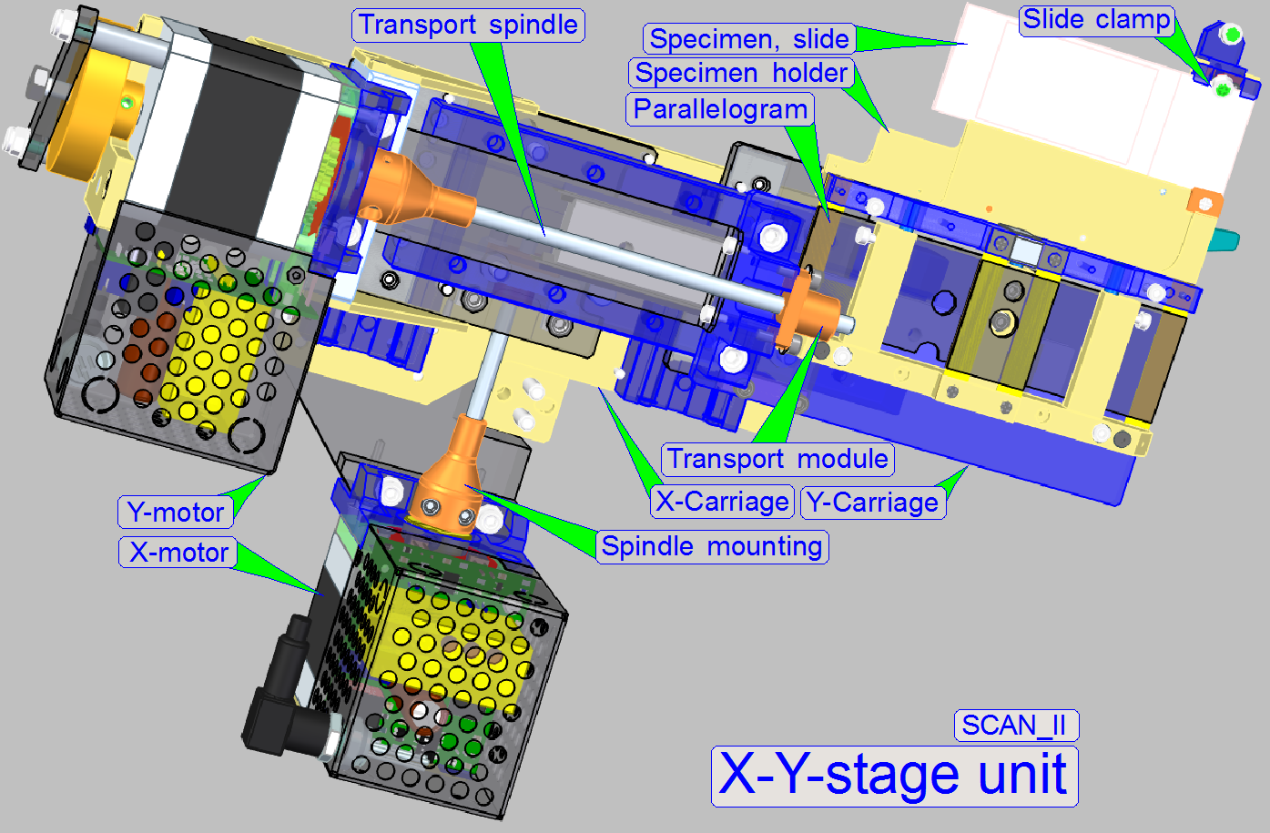
Watch video: X-Y-Stage; SCAN II
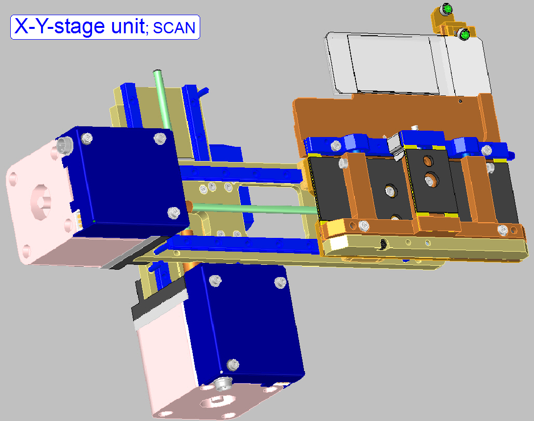
The X-Y-stage consists of the following components:
·
X-motor
·
Y-motor
·
X-rail
·
Y-rail
·
X-carriage
·
Y-carriage
·
X-spindle
·
Y-spindle
·
Parallelogram
·
Specimen holder
·
Slide clamp
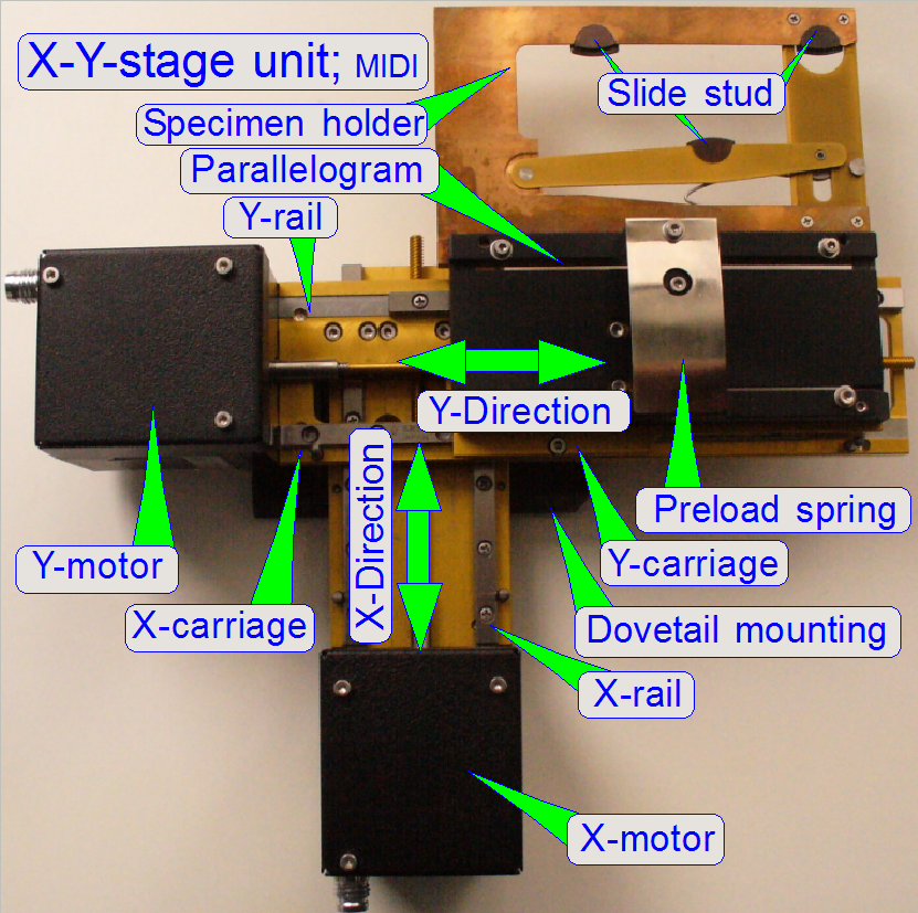
·
Slide stud (
·
Preload spring (
·
Dovetail foot (
The specimen holder is
designed to hold and secure the slide during scanning operation. It also allows
inserting or removing the slide automatically or manually. This part is
different in each Pannoramic scanner and will be
discussed separately.
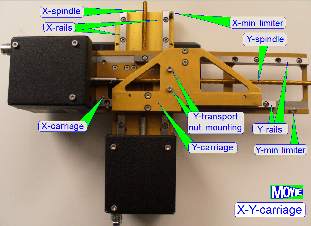
The rotor drives the transport nut through the spindle. The transport
nut is mounted to the carriage that is moving on the rails. The X-carriage
contains the entire Y-unit. The Y-carriage moves the parallelogram with the
specimen holder.
· The achieved
resolution in X- and Y-direction is: 1μm/rotor
step
· The movement range
of the X-carriage is 28800 rotor steps (it means 28.8mm)
· The movement range
of the Y-carriage is 73600 rotor steps (it means 73.6mm)
· The parts and
units of the carriages need neither maintenance nor mechanical adjustments.
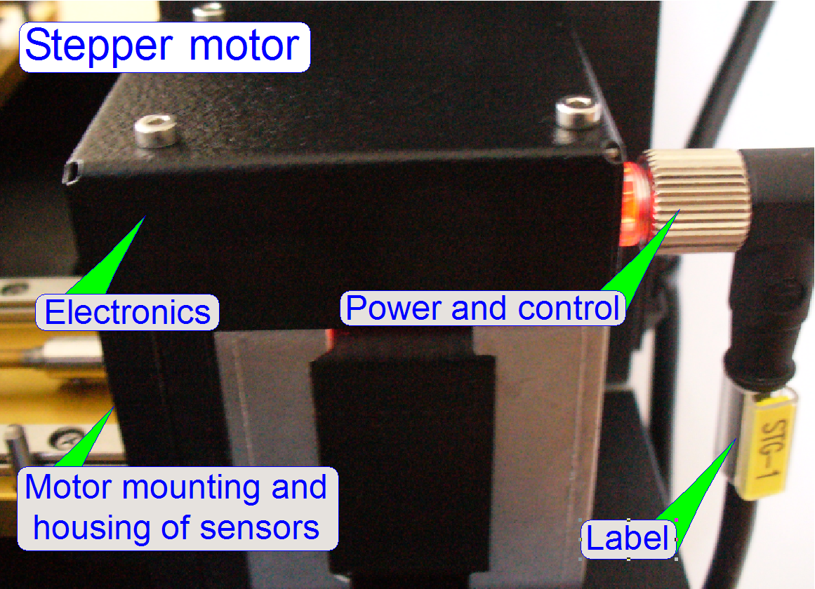
The X and Y-stage stepper motors are 2-phase type motors and are driven
in micro stepping mode. One revolution of rotor axle is divided into 3200µ-steps.
The forward direction of the motor axle is counter clockwise (CCW). The
construction of the mechanical X- and Y-drive together with the resolution of
the rotor movement allows a very precise movement of the specimen; the
resolution is 1µm.
· The address of the
X-motor is 03.
· The address of the
Y-motor is 04.
Note! The parts of the
stepper motors do not need maintenance or mechanical adjustments.
![]() “Stepper
motor”, “Addresses” and “Cabling of addressable
units”
“Stepper
motor”, “Addresses” and “Cabling of addressable
units”
 The dovetail foot of the X-Y-stage unit is found on the X-stage mounting
plate. It is fixed from beneath and ensures the proper position of the entire
X-Y-stage unit. If the dovetail foot is not tightened well, the
perpendicularity between the slide and the optical axis is not provided.
The dovetail foot of the X-Y-stage unit is found on the X-stage mounting
plate. It is fixed from beneath and ensures the proper position of the entire
X-Y-stage unit. If the dovetail foot is not tightened well, the
perpendicularity between the slide and the optical axis is not provided.
![]() “Exchange the X-Y-stage unit”,
“Scanner plate”, “X-Y-stage bumper” and “Dovetail fixing”.
“Exchange the X-Y-stage unit”,
“Scanner plate”, “X-Y-stage bumper” and “Dovetail fixing”.
Configuring the X-Y-stage unit
Since the software version 1.15, the scanner units are configured in the
“MicroscopeConfiguration.ini” file, in the [Microscope] section.
For more information about the 1.15 software version, see the Pannoramic SCAN 150
1.15 User’s Guide.
The actual version of the X-Y-stage unit in the S_M_D scanners is “ObjectGuideXYZType=OGXYZ_1”. Adjustment procedures are based on this version, except declared
otherwise.
[Microscope]
SerialNumber=xxxx
MicroscopeType=3DMic8
ScanCameraType=
PreviewCameraType=CVrmc_m8_pPro
BarcodeReaderType=PreviewCamera
LoaderType=SL_6Mag_25Slide_No_Sensor_Vertical
or SL_6Mag_25Slide_No_Sensor_Vertical2
ReflectorTurretType=RT_None
Note! ObjectGuideXYZType=OGXYZ_1; the
Y-direction is 23 rotor revolutions long; the specimen holder can hold slides
with a thickness of 0.95-
Removing the X-Y-stage unit
1. Move the X-stage to Home1.
 2. Move the X-stage to Home2.
3. Move the X-motor by +28000
steps.
4. Move the Y-stage to Home1.
5. Move the Y-stage to Home2.
6. Move the Y-motor by +70000
steps.
7. Loosen the focus unit fixing bolt by turning it
clockwise.
8. Remove the focus unit. For
more information about the focus unit removal, click here.
9. Loosen the X-Y-stage unit fixing bolt by turning
it clockwise.
10. Disconnect the cable and remove the X-Y-stage unit.

1. Insert the X-Y-stage unit
until it can not be pushed any further.
2. Tighten the fixing bolt by
turning it counter clockwise.
3. Connect the cables.
4. Insert the focus unit until it
can not be pushed any further.
5. Tighten the fixing bolt by
turning it counter clockwise.
6. Connect the cables.
For the mounting procedure,
see the video here.
![]() “Scanner plate”, “X-Y-stage bumper” and “Dovetail fixing”
“Scanner plate”, “X-Y-stage bumper” and “Dovetail fixing”
The carriages are used to
move the specimen holder and so the slide in X- and Y-directions.
The dovetail foot is mounted
onto the X-stage mounting plate from beneath. This ensures the proper mounting
and fixing of the X-Y-stage unit.
 The static part of the X-stage consists of
- X-direction mounting plate
- X-motor
- Dovetail foot (mounted from beneath)
- X-rails
- X-minimum limiter
- X-maximum limiter
The moveable part of the X-stage consists of
- X-stepper rotor
- Spindle
- Transport nut
- Spring
- Counter nut
- The Y-stage unit
The transport nut is on the
spindle, and the nut is mounted on the Y-stage unit with the spring and the
counter nut.
The transport nut is mounted
to the X-carriage.
The static part of the Y-stage consists of
 Y-direction
mounting plate
Y-direction
mounting plate- Y-motor
- Y-rails
- Y-minimum limiter
- Y-maximum limiter
The Y-motor is mounted to the
mounting plate.
The moveable part of the Y-stage consists of
- Y-stepper rotor
- Spindle
- Transport nut
- Y-carriage
- Parallelogram
- Specimen holder
The transport nut is mounted to
the Y-carriage.
The carriages are mounted and
lead with two rails for each direction.
The X- and Y-rails ensures a
slippage-free movement of the carriages in X- and Y-direction. The X-carriage
contains the entire Y-part. When the motor starts rotating, the spindle drives
the carriage in the direction, defined by the rotating direction of the rotor.
The mechanical dimensioning of the X-Y-stage allows reaching nearly each part
of the slide by the objective, except the barcode area (restrictions are given
by the slide holding mechanics of the specimen holder; see also
the scan area).

The spindle (together with the transport nut) is used to transform
rotation of the rotor into slippage-free longitudinal movements. The four
threads on the spindle guarantee a precise movement, increase the torque of the
mechanical drive and help to reduce or eliminate slippage and hysteresis.
The X- and Y-spindle are
connected directly to the
stepper motors. On the thread of the
spindle the transport nut is situated and the transport nuts
are mounted onto the X- respective Y-carriage. To eliminate slippage in the
connection between rotor axle and spindle, the spindles are fixed
with glue and secured by a bolt.
 The construction
of the carriage transport
nuts ensures a nearly slippage-free movement of the carriages, a maximal slip of 4 mm (=4 motor
steps) is allowed. The slippage of the transport nut is minimized by the use of
the counter nut and the compression spring.
The construction
of the carriage transport
nuts ensures a nearly slippage-free movement of the carriages, a maximal slip of 4 mm (=4 motor
steps) is allowed. The slippage of the transport nut is minimized by the use of
the counter nut and the compression spring.
The use of the stepper motors
micro stepping mode, combined with the accuracy of the mechanics allows
achieving a resolution of 1mm longitudinal movement per rotor step.
 The movement range
of each carriage is limited by two limiters, one for the upper and one for the
lower limit. Limiters are used for both the X- and Y-directions. With the limiters
the mechanical construction gets a start and an end position.
The movement range
of each carriage is limited by two limiters, one for the upper and one for the
lower limit. Limiters are used for both the X- and Y-directions. With the limiters
the mechanical construction gets a start and an end position.
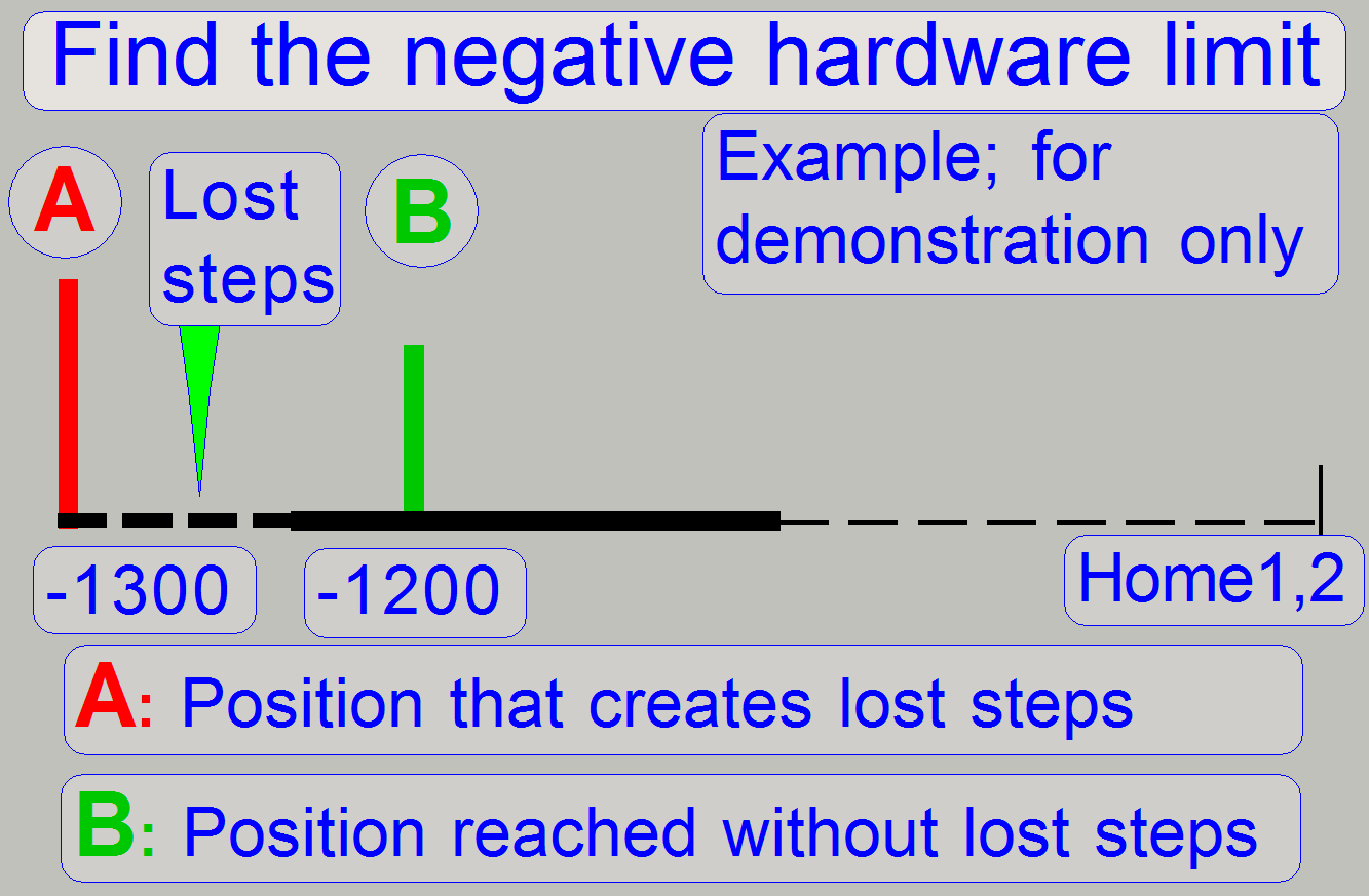
When the
mechanical limiter is reached by the carriage, the carriage movement stops. If more steps are
entered in the service program, those steps are lost - this behavior creates “lost
steps”.
During the detection of the
hardware limits the creation of lost steps is used to find and determine the
upper and lower hardware limits. The first number of steps that do not create
lost steps is used as hardware limit; the accuracy is 100 steps (0.1mm).
Example:
· If the step number
of 1200 steps in negative direction after Home1 and Home2 does create lost
steps (more than +-2 steps) and
· The step number of
1100 steps in negative direction after Home1 and Home2 does not create lost
steps (not more than +-2 steps) the negative hardware limit will be -1100
steps.
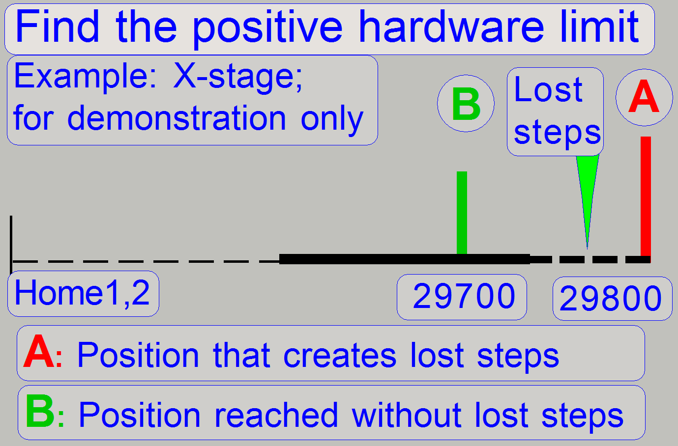
If the upper limit is
defined, the same principle is used. First we create lost steps then we
decrease the number of steps to go by 100 steps until no steps are lost during
the movement.
During slide insertion or removal actions and sample scanning process
lost rotor steps are unwanted, because the counting and reporting of steps
mismatches the real number of steps gone. Therefore, the limits are defined by
using the last possible number of steps without lost steps and an accuracy of
100steps (=0.1mm).
The home position does not
define the mechanical limit. Either in X- and or in Y-direction there are
several hundred more steps possible. The absolute limits are defined as shown
in the figures “X-direction; S_M_D”
and “Y-direction; S_M_D”.

Note! The unit is
faulty, if there are more than 1600 steps possible in negative direction from
Home 1,2 without stoppage.
The unit is faulty, if there are
more than 1600 steps possible in positive direction after 28800 steps in
+X-direction or 73600 steps in +Y-direction without stoppage.
![]() “Adjustment
procedures”, “How to
define the hardware limits” and “Check or define the hardware limits of the
X-Y-stage unit”
“Adjustment
procedures”, “How to
define the hardware limits” and “Check or define the hardware limits of the
X-Y-stage unit”


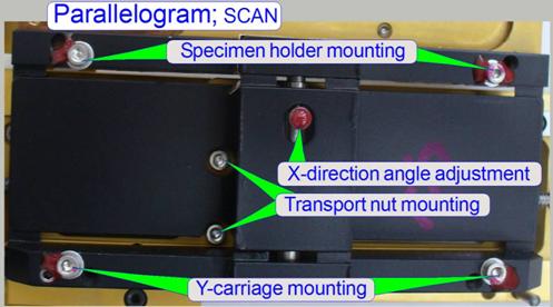
The parallelogram allows the
shifting of the X-Y-stage in Z-direction for focusing the FOV (Field of View)
without rotating the X-Y-stage. On one side of the parallelogram the Y-carriage
is mounted; on the other side the parallelogram holds the specimen holder.
The mounting bolts of the
parallelogram and the X-Y-stage adjustment bolt are adjusted, do not screw
them. The parallelogram and the
specimen holder are very sensitive components, because these guarantee the
X-Y-stage in relation to the objective. The parallelogram is not a
separate changeable spare part, therefore the
X-Y-stage or the entire scanner unit must be changed if there is an
irresolvable fault on the parallelogram.
Remark Do not adjust the parallelogram in the field, if
possible.
Watch slide show: Parallelogram
![]() How to adjust the
parallelogram
How to adjust the
parallelogram
Parallelogram
(SCAN)
The
parallelogram of the SCAN is from the same type, but the position and
construction of the preload spring is different.
In
Remark Do not adjust the parallelogram in the field, if
possible.
Watch slide show: Parallelogram
![]() How to adjust the
parallelogram
How to adjust the
parallelogram
Preload
spring
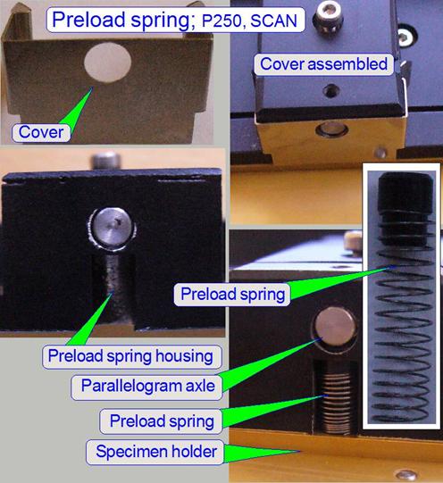 The preload spring is situated below the parallelogram axle,
perpendicularly in the preload spring housing. It is responsible for moving the
slide during specimen focusing.
The preload spring is situated below the parallelogram axle,
perpendicularly in the preload spring housing. It is responsible for moving the
slide during specimen focusing.
There is a
If the parallelogram needs to
be replaced separately or the mounting bolts were loosened, the parallel
shifting of the specimen during focusing must be adjusted.
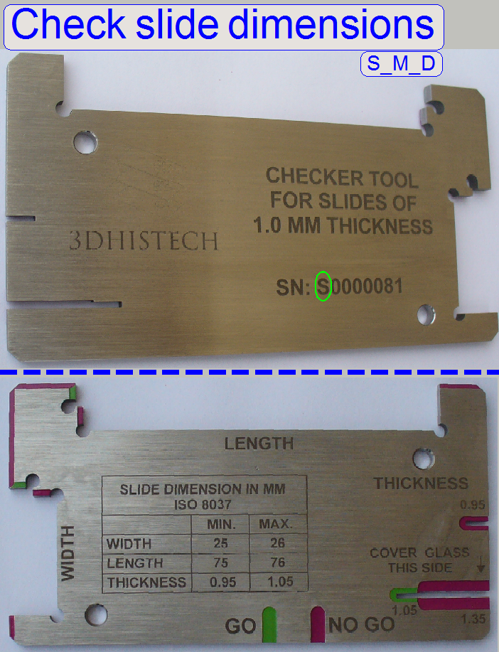
Length: 75.00 to
Width: 25.00 to
Thickness: 00.95 to
Since January
- If the first
character of the serial number is an “S” the tool is used to
check the slide dimensions of the “SCAN, “
- If the first
character of the serial number is a “P” the tool is used to
check the slide dimensions of the “P250” scanner.
Note! Check the slide
dimensions before slide insertion.
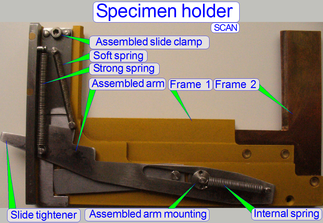
Specimen holder; SCAN
 The specimen
holder is designed to hold the slide and to secure it during scanning process. The
holder also allows an automatic slide change operation. To loosen the slide
during insertion or removing procedures, the slide tightener
opens the slide clamp. If the Y-stage is in Home1,2 position, or only some 100
steps away from it and the X-Y-stage moves upward (-X-direction), the slide tightener contacts the magazine unit from below, the slide tightener moves downward and stretches so the „Strong
spring”.
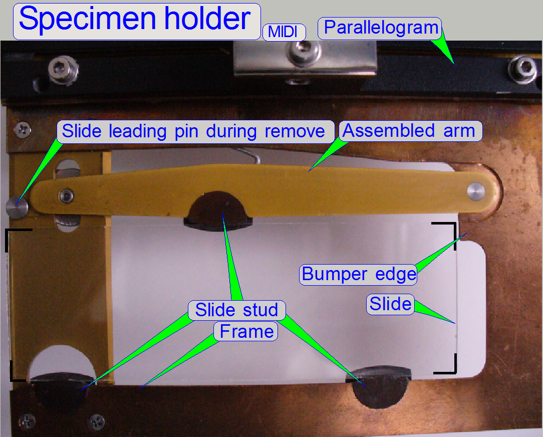
The specimen
holder is designed to hold the slide and to secure it during scanning process. The
holder also allows an automatic slide change operation. To loosen the slide
during insertion or removing procedures, the slide tightener
opens the slide clamp. If the Y-stage is in Home1,2 position, or only some 100
steps away from it and the X-Y-stage moves upward (-X-direction), the slide tightener contacts the magazine unit from below, the slide tightener moves downward and stretches so the „Strong
spring”.
The „Internal spring” forces the
„Assembled arm” (and so the slide tightener also)
always in its right position, mainly if there was an unwanted collision with
the magazine unit.
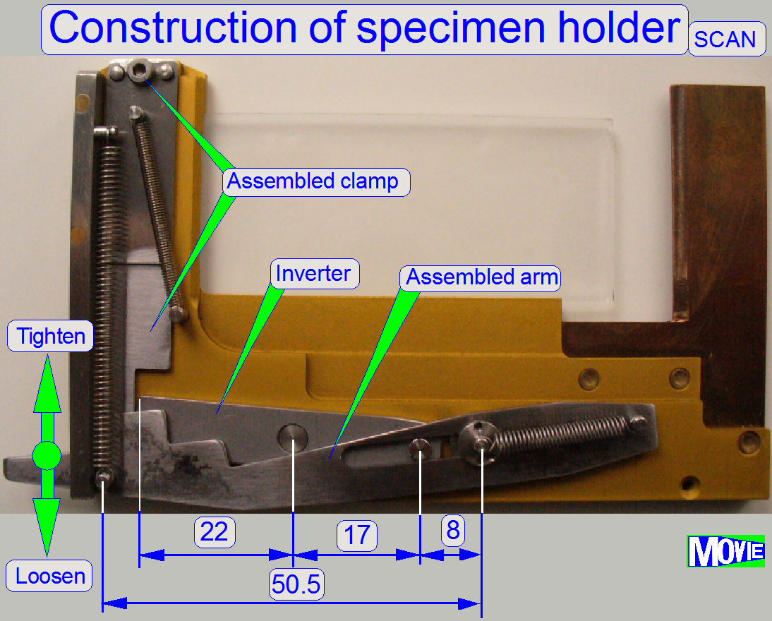
 During scanning the slide tightener is not in contact with the magazine unit. The
slide is tightened by the “Strong spring” to ensure, that the slide does not
change its position in the frame. The force of the „Strong spring” is 2N
±0.5N. Through the „Assembled arm” and the „Inverter”, the ”Strong
spring” forces the ”Assembled clamp” downward in relation 50.5 : 8 (the “Assembled arm” amplifies the
force of „Strong spring”) and in relation 17:22 the ”Inverter” attenuates a
little bit this force, but its main task is, to invert the movement. This way
the force of the slide clamp against the slide is nearly five times more than
the force of the “Strong spring”.
During scanning the slide tightener is not in contact with the magazine unit. The
slide is tightened by the “Strong spring” to ensure, that the slide does not
change its position in the frame. The force of the „Strong spring” is 2N
±0.5N. Through the „Assembled arm” and the „Inverter”, the ”Strong
spring” forces the ”Assembled clamp” downward in relation 50.5 : 8 (the “Assembled arm” amplifies the
force of „Strong spring”) and in relation 17:22 the ”Inverter” attenuates a
little bit this force, but its main task is, to invert the movement. This way
the force of the slide clamp against the slide is nearly five times more than
the force of the “Strong spring”.
 During slide insert and removal operations, the slide tightener is moved downward and so, the mechanics, driven
by the “Assembled arm” loosens the “Slide clamp” via the “Inverter” mechanics.
Only the force of the “Soft spring” holds now the slide in the frame. Because
the force of the “Soft spring” is not much, the slide can be inserted or
removed easily by the slide loader.
During slide insert and removal operations, the slide tightener is moved downward and so, the mechanics, driven
by the “Assembled arm” loosens the “Slide clamp” via the “Inverter” mechanics.
Only the force of the “Soft spring” holds now the slide in the frame. Because
the force of the “Soft spring” is not much, the slide can be inserted or
removed easily by the slide loader.
·
Please do not exceed the allowed slide dimensions;
otherwise, the slide clamp may be damaged!
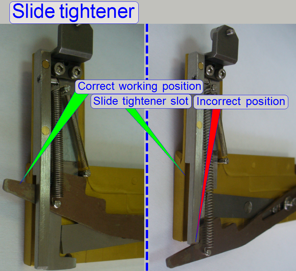
·  Please check the
correct slide tightener’s position in its slot, if
the X-Y-Stage unit was inserted and also, if the slide was inserted or removed
manually!
Please check the
correct slide tightener’s position in its slot, if
the X-Y-Stage unit was inserted and also, if the slide was inserted or removed
manually!
![]() “Insert or
remove the slide manually”
“Insert or
remove the slide manually”
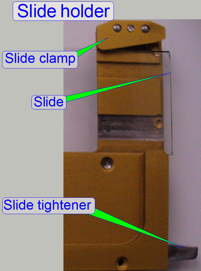
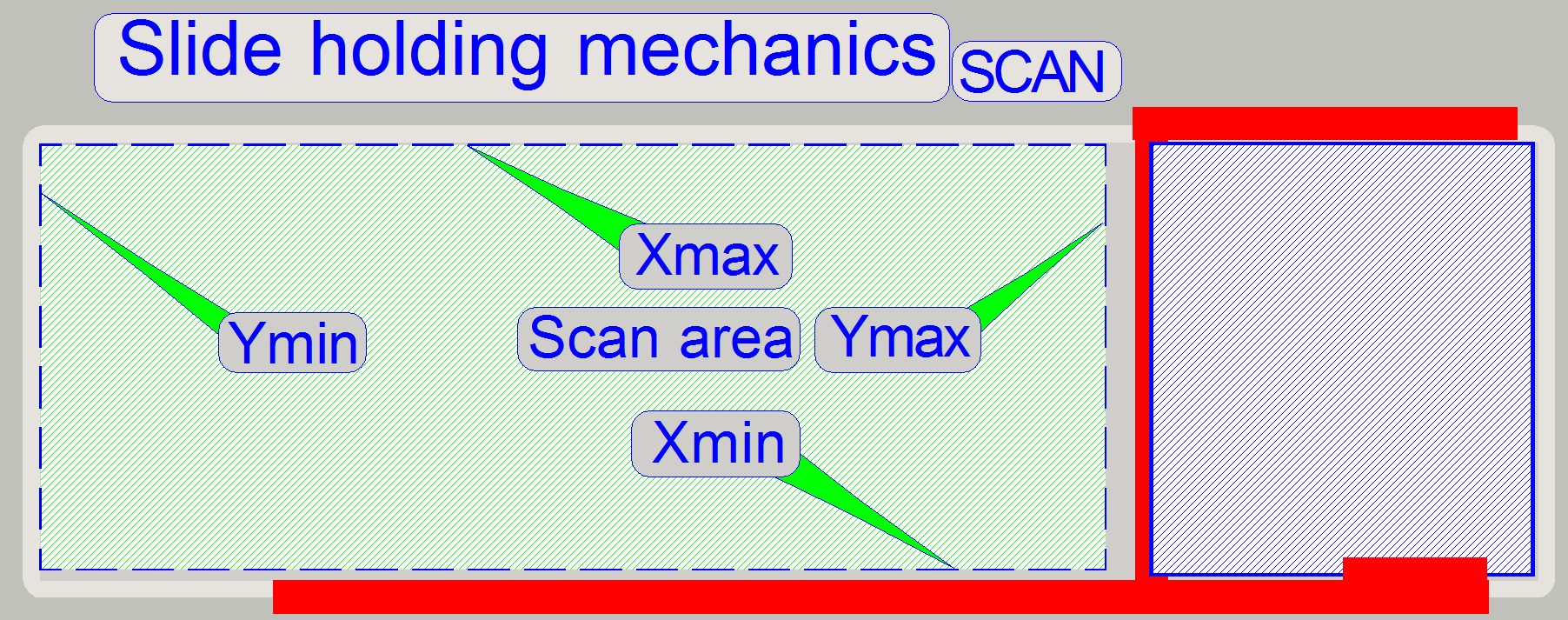
Slide holding and scan area; SCAN
 The slide is hold
by the specimen holder on the longer, lower edge and with a slide clamp on its
upper edge, on the barcode area; see the red lines on the right. As you can
see, the definition of the limits X-min and Y-max are critical. X-max and Y-min
are given by the maximal usable slide size and are not critical; they could be
the slide edge.
The slide is hold
by the specimen holder on the longer, lower edge and with a slide clamp on its
upper edge, on the barcode area; see the red lines on the right. As you can
see, the definition of the limits X-min and Y-max are critical. X-max and Y-min
are given by the maximal usable slide size and are not critical; they could be
the slide edge.
·
Never touch the specimen holder with the
objective or the focus pin!
![]() “Areas of the slide”, “Define the scan area” and “Construction of specimen holders”
“Areas of the slide”, “Define the scan area” and “Construction of specimen holders”
Specimen
holder;
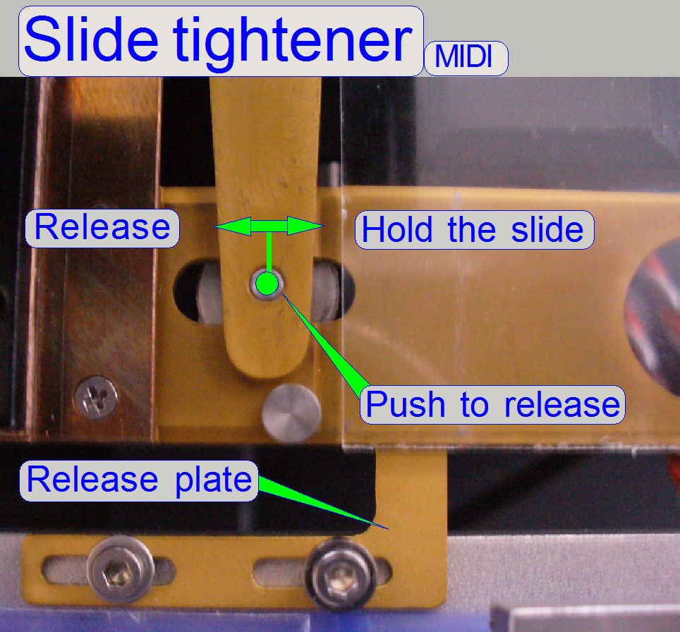 In its released state
the “Assembled arm” is forced by the spring to hold the slide via the studs. If
the slide will be inserted or removed, the Y-motor goes to slide insert or
remove position and the X-stepper goes forward nearly to its positive limit and
contracts the spring in “push” direction via an arm mounted beneath of the tray
holder (the release plate), to release the slide. The longest allowed slide
(76,00mm) will be inserted nearly until the bumper edge.
In its released state
the “Assembled arm” is forced by the spring to hold the slide via the studs. If
the slide will be inserted or removed, the Y-motor goes to slide insert or
remove position and the X-stepper goes forward nearly to its positive limit and
contracts the spring in “push” direction via an arm mounted beneath of the tray
holder (the release plate), to release the slide. The longest allowed slide
(76,00mm) will be inserted nearly until the bumper edge.
 If the
specimen holder is in Y-Home1,2 position and moves in
–X-direction the “Assembled arm” is touched from below by the release plate; so
the slide is loosened and can be inserted or removed with the slide loader.
If the
specimen holder is in Y-Home1,2 position and moves in
–X-direction the “Assembled arm” is touched from below by the release plate; so
the slide is loosened and can be inserted or removed with the slide loader.
Attention!
- Never
cross the slide stud with the focus pin or the objective!
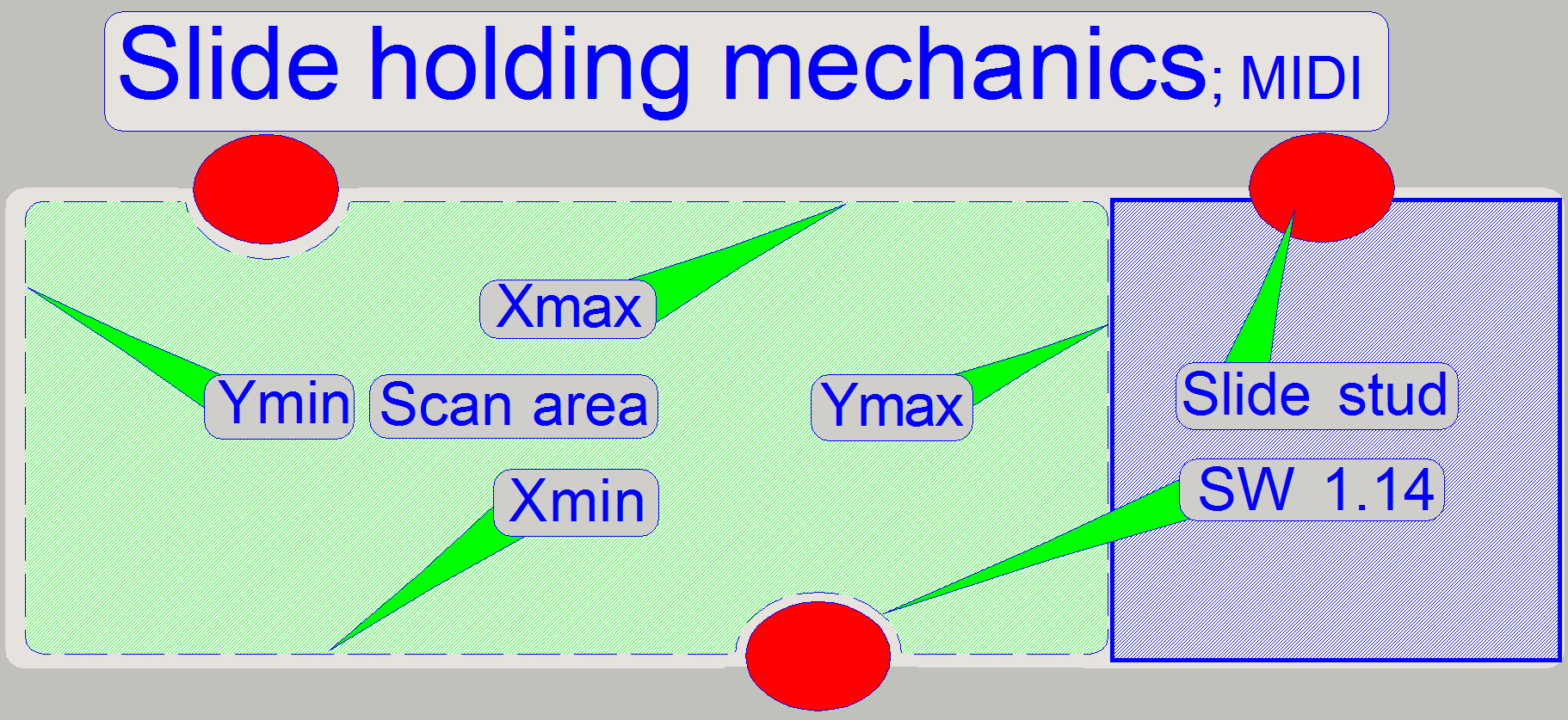
Slide holding and
scan area;
 The
slide is held in the specimen holder with the help of three slide studs,
situated on the longer edges as shown.
The
slide is held in the specimen holder with the help of three slide studs,
situated on the longer edges as shown.
The surrounding of the slide stud is left out automatically from the
scan process since the software version 1.14 and needs not to be excluded
manually from the scan area (until the SW version 1.16).
·
Never touch the slide stud with the
objective!
![]() “Areas of the slide”, “Define the scan area” and “Construction of
specimen holders”
“Areas of the slide”, “Define the scan area” and “Construction of
specimen holders”
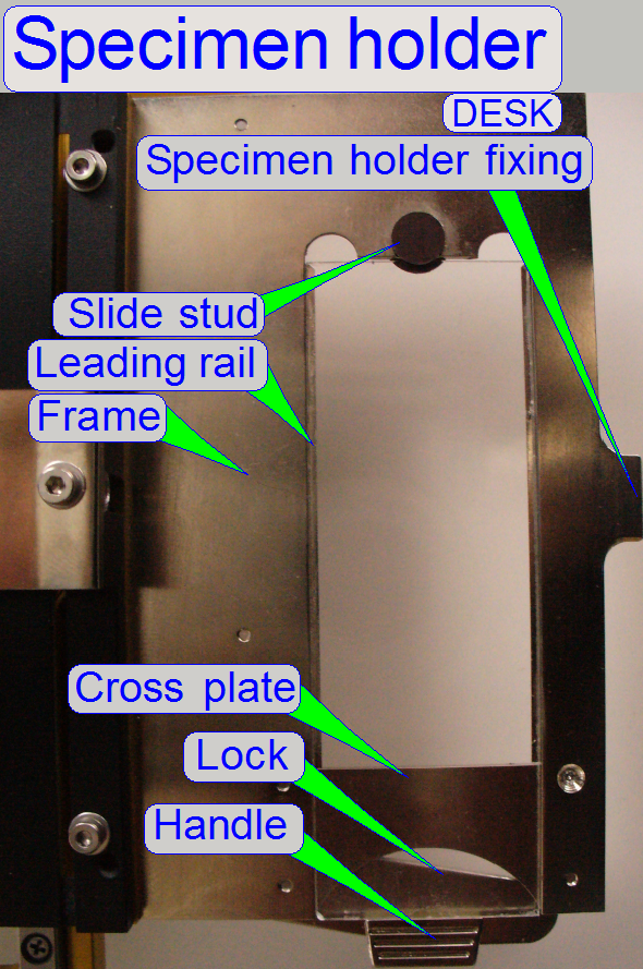
Specimen holder; DESK
 Because the slide is inserted
manually, this part of the Specimen holder is modified and leading rails for
the slide are added.
Because the slide is inserted
manually, this part of the Specimen holder is modified and leading rails for
the slide are added.
The user opens the lock by
pulling the handle. During inserting the slide manually the slide reaches the
cross plate and is then, during shifting the slide, leaded by the leading rails
on both sides. The slide movement into the specimen holder is stopped by the
slide stud; it holds the slide at its inner, shorter edge. After closing the
lock, the shape and construction of the handle and the stud guarantees, that
the slide is always inserted well. The lock spring forces the lock and so the
slide against the stud. Because there is always a force on the lock and so on
the slide also, the slide position will not be changed during the scan process.
Attention!
·
Never
cross the slide stud with the focus pin or the objective!
The slide stud in the DESK should be able to hold the thickest
allowed slide together with the cover slip. Use the test slide to
check the slide stud size in the DESK.
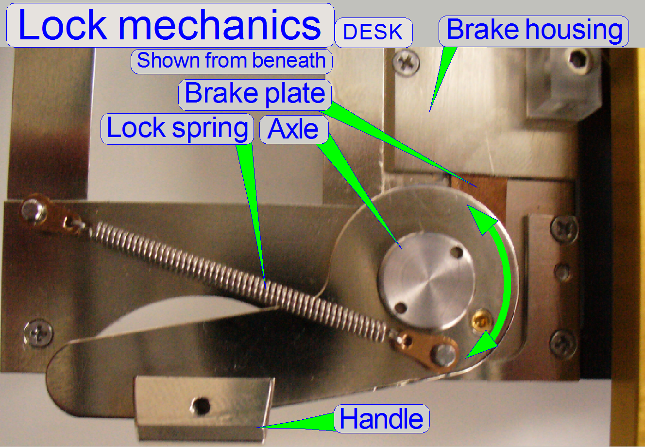
 During opening and
closing the lock a brake plate is moved in the brake housing also. The brake
housing contains brake grease. This way, if the brake plate moves in the brake housing
a mechanical resistance is generated and so, the lock closes slowly.
During opening and
closing the lock a brake plate is moved in the brake housing also. The brake
housing contains brake grease. This way, if the brake plate moves in the brake housing
a mechanical resistance is generated and so, the lock closes slowly.
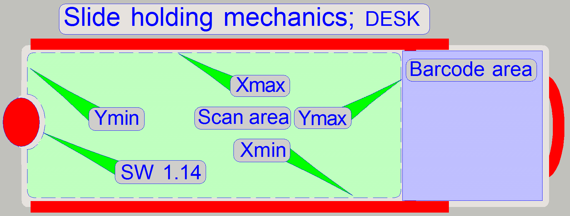
Slide holding and scan area; DESK
 The
slide is held in the specimen holder by the help of one slide stud on the shorter,
inner edge and by the lock handle on the outer, shorter edge. Furthermore,
along the longer edges of the slide there are leading rails situated to lead
the slide during slide insertion. All this facts should be taken into account
if the scan area is defined. The surrounding of the slide stud is left out
automatically from the scan process since the software version 1.14 and needs
not to be excluded manually from the scan area. If you are working with the
service program take care of the focus pin and the objective.
The
slide is held in the specimen holder by the help of one slide stud on the shorter,
inner edge and by the lock handle on the outer, shorter edge. Furthermore,
along the longer edges of the slide there are leading rails situated to lead
the slide during slide insertion. All this facts should be taken into account
if the scan area is defined. The surrounding of the slide stud is left out
automatically from the scan process since the software version 1.14 and needs
not to be excluded manually from the scan area. If you are working with the
service program take care of the focus pin and the objective.
·
Never touch the slide stud with the focus pin or the objective!
![]() “Areas of the slide”, “Define the scan area” and “Construction of
specimen holders”
“Areas of the slide”, “Define the scan area” and “Construction of
specimen holders”
Adjustments for the X-Y-carriage unit

The following procedures are described
for Pannoramic SCAN especially. In Pannoramic MIDI and Pannoramic
DESK the adjustments are logically identical, but some pronunciations like “up
or down and left or right, horizontal and vertical” may differ. Please take
this into account if you are adjusting DESK or
Find the hardware limits
for the X-carriage
·
 This procedure must be done
if the scanner unit or the X-Y-stage was changed; the parallelogram was
adjusted, the specimen holder mounting was altered or the drive unit was
manipulated.
This procedure must be done
if the scanner unit or the X-Y-stage was changed; the parallelogram was
adjusted, the specimen holder mounting was altered or the drive unit was
manipulated.
· Insert a medium large slide (manually) and
set the focus motor to 800 steps.
![]() “How to define the hardware limits”,
“Insert or
remove a slide manually”
“How to define the hardware limits”,
“Insert or
remove a slide manually”
 Find the negative limit
in -X-direction
Find the negative limit
in -X-direction
1. With the service program set
the Y-carriage to Home1,2.
2. Set the X-carriage to Home1,2.
3. With the service program go
forward to the X-motor position -1200 steps.
4. Go backward +1200 steps.
5. Press Home1 (only). There
should be not more then +-2 steps difference to Home1. If there are more steps
lost, decrease the actual absolute number of steps by 100 and repeat from step
6. If there are not more then 2
steps difference to Home1, increase the number of steps by 100 and repeat from
step
7. The negative limit is found
correctly if the motor movement has no steps lost and the actual absolute
number of steps, increased by 100 would produce lost steps. The found negative
limit can differ by more 100 steps from unit to unit. The reason is the tolerance
of the components.
8. Update the value of the
parameter “ObjectGuideXMin” with the found number of
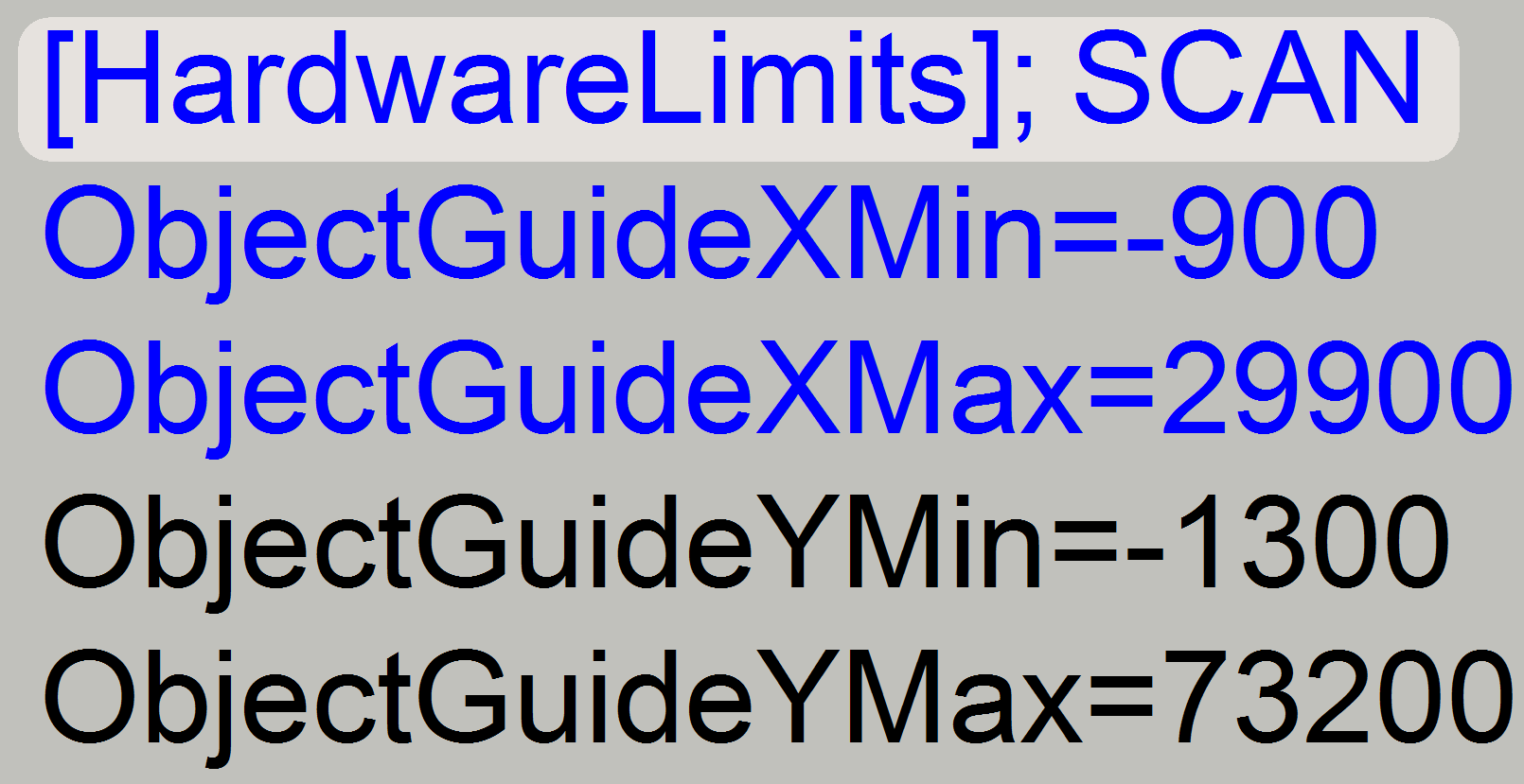
the actual steps in the file “MicroscopeConfiguration.ini” section [HardwareLimits] and save the file.
Find the positive limit
in +X-direction
 With the service
program set the X-carriage unit to Home1,2.
With the service
program set the X-carriage unit to Home1,2.
9. Go forward to the X-motor
position +29700 steps.
10. Go backward 29700 steps.
11. Press Home1 (only). There should be not more
then +-2 steps difference to Home1. If there are more steps lost, decrease the
actual number of steps by 100 and repeat from step
12. If there are not more then 2 steps difference to
Home1, increase the number of steps by 100 and repeat from step
13. The positive limit is found correctly if the
motor movement has no steps lost (max. 2 steps) and the actual number of steps,
increased by 100 would produce lost steps. The found positive limit can differ
by more 100 steps from unit to unit. The reason is the tolerance of the
components.
14. Update the value of the parameter “ObjectGuideXMax” with the found value in the file “MicroscopeConfiguration.ini”
section [HardwareLimits] and save the file.
·
Check the found limits by using the number of steps,
used as parameter value in the file “MicroscopeConfiguration.ini” section [HardwareLimits]. Lost steps must not occur.
Find the hardware limits for the Y-carriage
For SCAN: Move the X-carriage
+29000 steps from Home1,2; this way, the slide tightener can not collide with the magazine unit and the
focus pin does not collide with the lower edge of the specimen holder.
For
For DESK: Move the X-carriage
+6400 steps from Home1,2; this way, the focus pin does
not collide with the slide stud or the slide rails of the specimen holder.
Find the negative limit
in -Y-direction
Repeat the steps,
described in the procedure above “To find the negative limit in -X-direction”
logically with the Y-carriage.
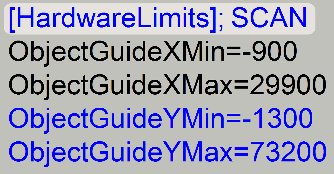
15. Update the value of the parameter “ObjectGuideYMin” with the found number of the actual steps
in the file “MicroscopeConfiguration.ini” section [HardwareLimits]
and save the file.
Find the positive limit
in +Y-direction;
Repeat the steps,
described in the procedure above “To find the positive limit in +X-direction”
logically with the Y-carriage. The positive limit is found correctly even before
the +Y-limit is reached or before the specimen holder will be touched (SCAN,
DESK).
16. Update the value of the parameter “ObjectGuideYMax” with the found value in the file “MicroscopeConfiguration.ini”
section [HardwareLimits] and save the file.
Further
information can be found in: “How to define the hardware limits”
and “Check or define the hardware limits of the
X-Y-stage unit.”
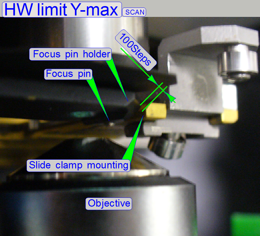
Important restriction in
the SCAN!
 The
possible maximal movement limit of the Y-carriage can not be used in the system
as hardware limit because collision of the focus pin holder with the slide
clamp (mounting) would occur.
The
possible maximal movement limit of the Y-carriage can not be used in the system
as hardware limit because collision of the focus pin holder with the slide
clamp (mounting) would occur.
·
Move the X-carriage +29000 steps
from Home1,2; this way, the slide tightener
can not collide with the magazine unit and the focus pin holder does not
collide with the lower edge of the specimen holder.
·
Move the Y-carriage in direction to
the limit “Y-max” until a gap of 0.1mm (= 100 steps) exists between the focus
pin holder and the slide clamp (mounting)!
The value is found in the
near of 73000 steps
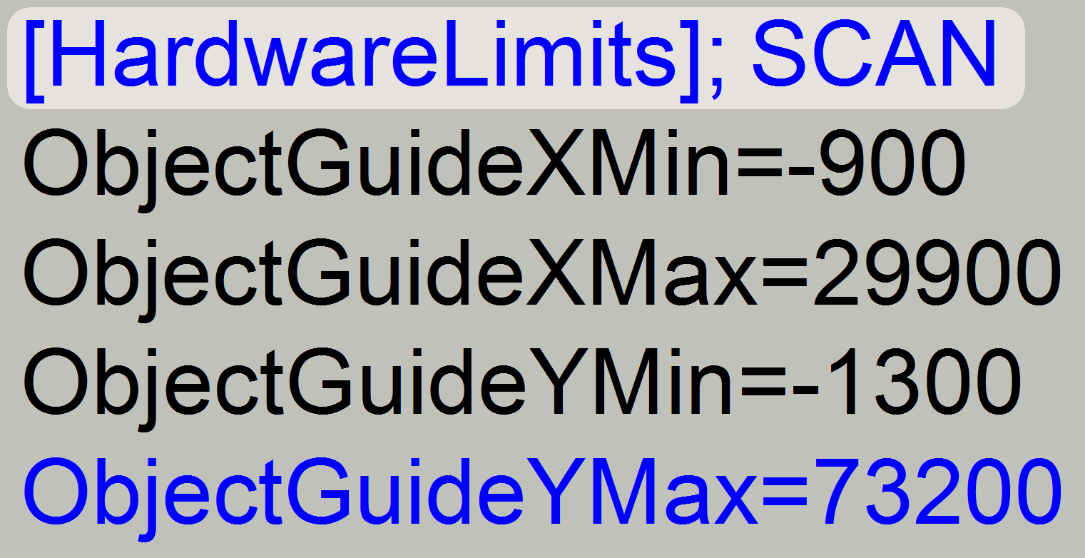
·
Update the value of the
parameter “ObjectGuideYMax” in the file “MicroscopeConfiguration.ini” section [HardwareLimits] with the found value and save the file.
![]() “How to define the hardware limits”
and “Check or define the hardware limits of the X-Y-stage unit.”
“How to define the hardware limits”
and “Check or define the hardware limits of the X-Y-stage unit.”
 The software divides the sample to be
scanned, seen by the preview camera into fields of views; the size of the FOV
depends on the resolution of the scan camera and the magnification of the
camera adapter. Each field of view contains a small part of the neighbor FOV.
In this way, stitching becomes possible. Because the capturing of the FOV’s is done on a meandering course, the Y-direction is
often changed. If the hysteresis in Y-direction is too much, stitching will not
work correctly; therefore, we have to check the hysteresis in Y-direction. The
maximal allowed hysteresis is 4 μm (=4 motor
steps). We comment that this hysteresis decreases itself by some motor steps
after some sample scan procedures, mainly if the X-Y-stage is brand new.
The software divides the sample to be
scanned, seen by the preview camera into fields of views; the size of the FOV
depends on the resolution of the scan camera and the magnification of the
camera adapter. Each field of view contains a small part of the neighbor FOV.
In this way, stitching becomes possible. Because the capturing of the FOV’s is done on a meandering course, the Y-direction is
often changed. If the hysteresis in Y-direction is too much, stitching will not
work correctly; therefore, we have to check the hysteresis in Y-direction. The
maximal allowed hysteresis is 4 μm (=4 motor
steps). We comment that this hysteresis decreases itself by some motor steps
after some sample scan procedures, mainly if the X-Y-stage is brand new.
Because the X-direction is
never changed during a sample scan process, the X-hysteresis is not critical
and can be some steps more (max: 8 steps).
Watch video: “Tissue scan
process” (P250)
Check the maximal
hysteresis in Y-direction

Start the program “SlideScanner.exe”
with the service password. In the tab “Focus” produce a sharp life view.
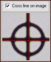
In the tab “Service” select
“Microscope control” and check the option “Cross line on image”. In the part of
the X-Y-control select a step size of two steps and go upward, until the tissue
moves.
Now go in opposite direction
and count the clicks until the tissue moves. If more then 3 clicks are
required, the hysteresis is too much.
![]() “Stitching” and “Exchange the Y-drive
unit”
“Stitching” and “Exchange the Y-drive
unit”
The following adjustments are done only, if the motor has to be exchanged,
the X-Y-carriage drive unit was removed or the hysteresis in X- or Y-direction
is too much.
The resolution of the stepper motor by 3200 steps/revolution and
the construction of the spindle together with the transport nut allow a
resolution of 1μm longitudinal movement per motor step; the counter nut
with spring reduces the slippage (resulting in hysteresis) if the rotation
direction changes.
The only difference between the Y-carriage drive unit and the X-
carriage drive unit is the length of the transport spindle; the spindle of the
X-unit is shorter.
Transport
spindle; Multi (4) thread spindle
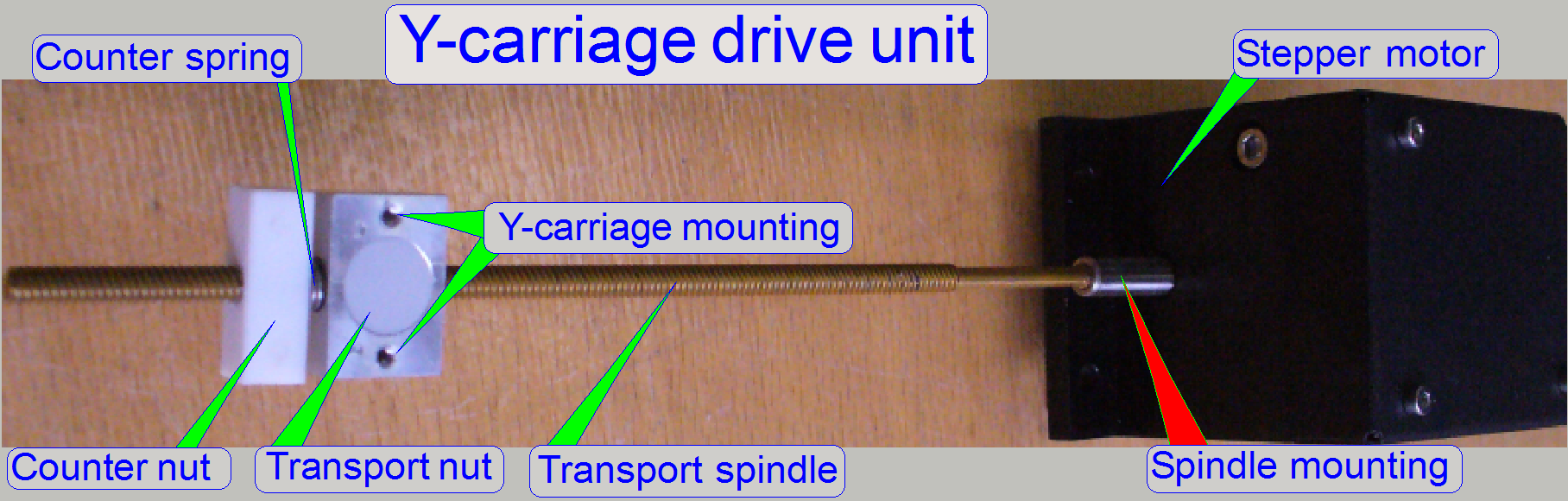
The spindle (together with the transport nut) is used to transform
rotation into slippage free longitudinal movements. The four threads on the spindle
guarantee a precise movement, increase the torque of the mechanical drive and
help to reduce or eliminate slippage and hysteresis.
 The spindle is glued
into the motor axle and fixed with a 1.5mm worm bolt; this guarantees a
slippage free connection.
The spindle is glued
into the motor axle and fixed with a 1.5mm worm bolt; this guarantees a
slippage free connection.
·
Remove the worm bolt by using a 0.9mm hex key wrench.
·
Heat up the spindle mounting until approx.
300º C and
·
Pull out the spindle from the motor axle and remove
glue residues from the spindle shaft.
·
Put some drops LOCTITE 603 glue onto the spindle shaft
·
Insert the spindle shaft into the motor axle’s
drilling
·
Insert and tighten the worm bolt
·
Remove unused LOCTITE glue from the spindle
shaft and the motor axle
·
Check and correct the center of the connection; if the
motor rotates, the spindle end should stay nearly in the center; minimize the
elongation of the spindle end during rotation.
·
The LOCTITE glue should dry up 24 hours before the use
of the carriage drive unit.
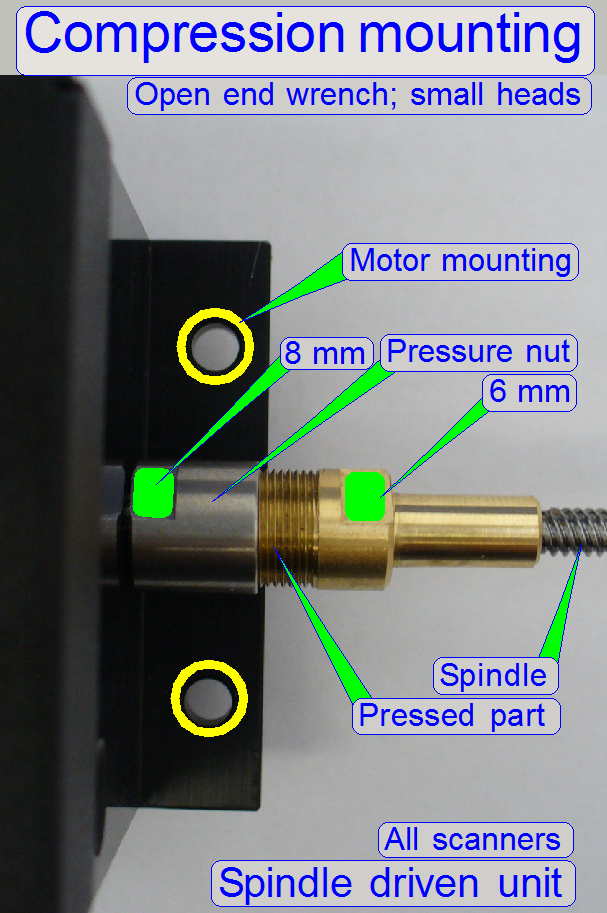
Spindle
mounting; since 2014
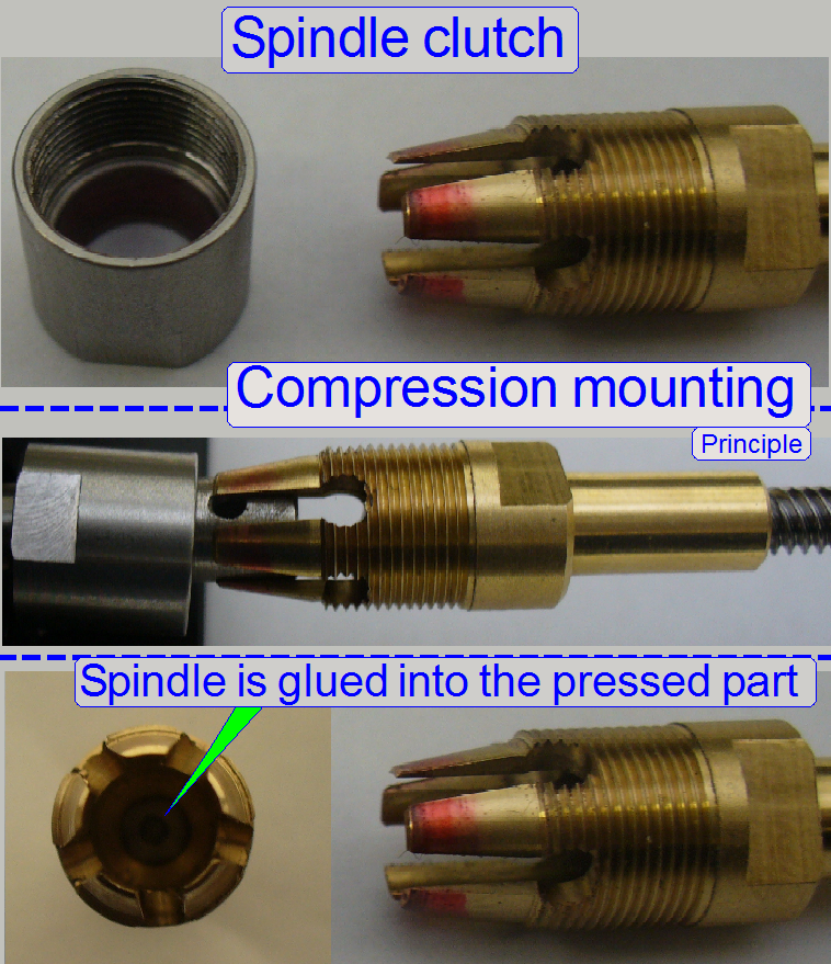
 The spindle is
mounted to the motor axle by using a compression mounting; this guarantees also
a slippage free connection and the spindle can be dismounted from the motor
axle.
The spindle is
mounted to the motor axle by using a compression mounting; this guarantees also
a slippage free connection and the spindle can be dismounted from the motor
axle.
This mounting construction guarantees also a centered mounting of the
spindle.
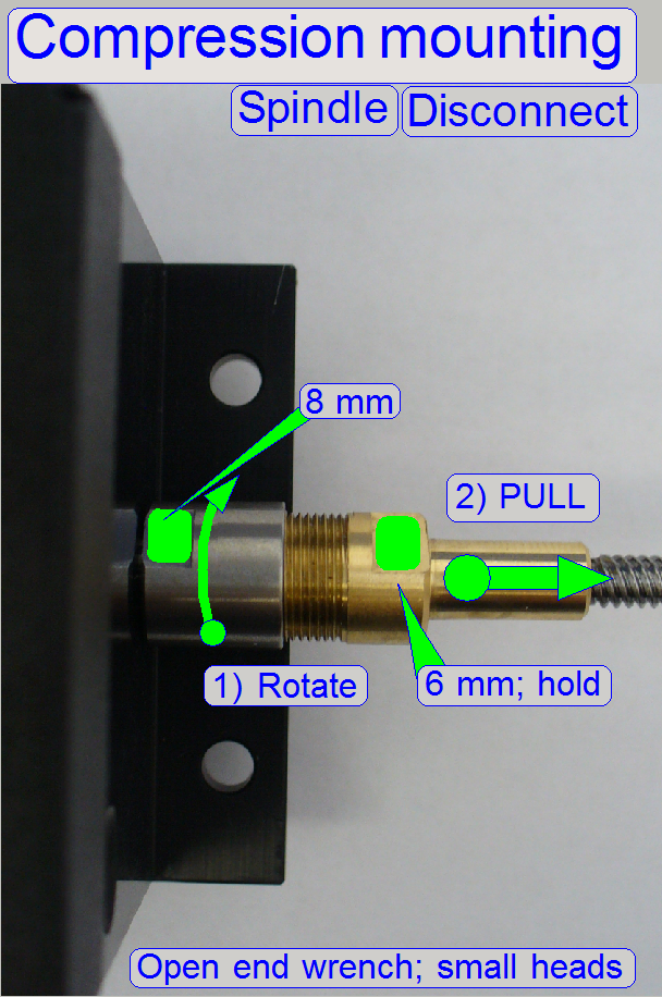
· The pressure nut
can be rotated with a small
head 8mm open end wrench, the pressed part can be hold with a small head
6mm open end wrench!
· Loosen the
pressure nut and pull the pressed part from the rotor axle.
The claws of the pressed part are fitting the diameter of the rotor
axle; the spindle is glued into the pressed part.
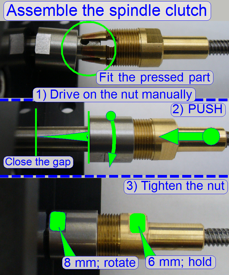
Assemble
the connection
· Put the pressure
nut in the right direction onto the motor axle.
· Fit the claws onto
the rotor axle.
· Drive the pressure
nut onto the pressed part manually, until it stops.
· Push the pressed part
on the rotor axle against the motor housing until it stops.
· Hold the pressed
part with the 6mm wrench and drive the pressure nut with the 8mm wrench.
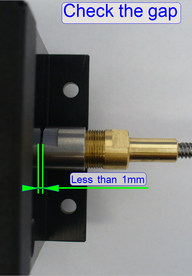
· The connection is
correct, if the pressed part is hold on the rotor axle and the gap between
pressure nut and motor housing is not more then 1mm.
·  The gap between
the pressure nut and the motor mounting must not exceed 1mm!
The gap between
the pressure nut and the motor mounting must not exceed 1mm!
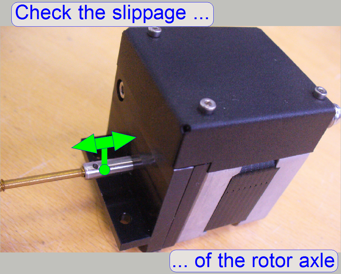
 Another important source
of slippage can be the rotor bearing of the motor. Because the rotor has
longitudinal load also, the position of the ball bearings of the rotor must not
change if the rotation direction is changed; the motor axle must not have
slippage.
Another important source
of slippage can be the rotor bearing of the motor. Because the rotor has
longitudinal load also, the position of the ball bearings of the rotor must not
change if the rotation direction is changed; the motor axle must not have
slippage.
To check the slippage of the motor axle manually, use a force of about 3
N. There have no movement to be expired. Take into account, that a slip of
Eliminate the slippage of the rotor axle
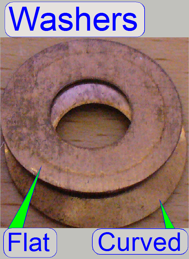
 Originally, the rotor
bearing has a spring to eliminate the slip, but the force of the original
spring is often not enough; mainly if the motor axle has a longitudinal load
like in the X- or Y-carriage. Therefore the original solution was exchanged by
using a flat and a curved washer; the curved washer acts as a spring.
Originally, the rotor
bearing has a spring to eliminate the slip, but the force of the original
spring is often not enough; mainly if the motor axle has a longitudinal load
like in the X- or Y-carriage. Therefore the original solution was exchanged by
using a flat and a curved washer; the curved washer acts as a spring.
If both washers are inserted well, the slip must be eliminated.
1.
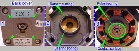 Remove the cover
mounting bolts of the motor (1).
Remove the cover
mounting bolts of the motor (1).
2.
Pull the back cover carefully backward and put it onto
the table as shown (2).
3.
Insert the flat washer first; then the curved washer
so, that its perimeter contacts the rotor bearing as shown (3).
4.
Fit the back cover to the motor and take care of the
washers.
5.
Drive in the mounting bolts of the back cover; check
the easily movement and the fitting of the rotor, then tighten the mounting
bolts and check the easily movement of the rotor again by hand.
6.
Check the correct movement of the rotor with the
service program and listen the sound also; rotate the motor by more ten turns
forward and backward some times.
7.
If there can be a sliding or sanding sound listened or
the rotor moves strong, loosen the mounting bolts again a little bit and fit
the rotor mounting more precise.
Transport- and counter nut with spring
 The transport nut
moves the Y-carriage (or any other, connected peripheral) to the desired
position; the thread of the spindle and the nut moves the peripheral by
The transport nut
moves the Y-carriage (or any other, connected peripheral) to the desired
position; the thread of the spindle and the nut moves the peripheral by
To reach the appropriate limits of the mechanical drive, the position of
the transport nut on the spindle is important; the position can be defined with
an accuracy of a ¼ full turn (because there are 4 threads), it means 800
motor steps.
The limits have to be less then 1600 steps in negative direction counted
from Home1,2 and less then 1600 steps after 23 full turns of the spindle (if
Y-carriage); see also “The hardware limits”
and “Find the hardware limits for
the Y-carriage”; both limits have to be fulfilled if the adjustment is
finished; otherwise dismount
the carriage drive unit, define the position of the transport nut in
relation to the spindle with +- ¼ full turn, mount the carriage drive unit
and check the limits again.
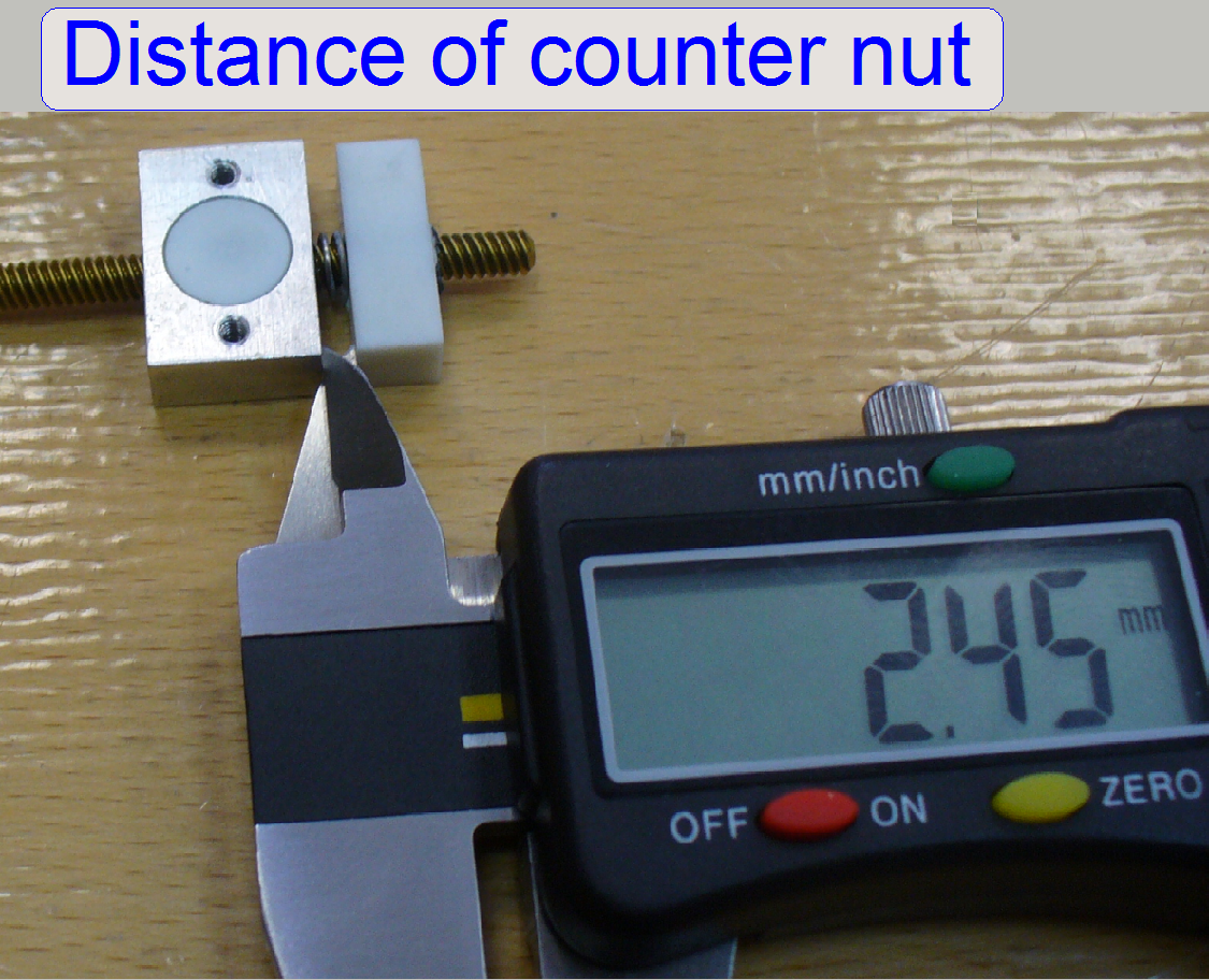
 To eliminate any slip
of the mechanical drive (to reduce or eliminate the hysteresis), the spring
forces the transport nut away from the counter nut. The force of the spring
guarantees the appropriate pressure of the transport nut against the threads of
the spindle. By using the appropriate start point of the threads, the counter
nut can be positioned in relation to the transport nut in the same way as the
transport nut; the position can be defined by a ¼ full turn (because
there are 4 threads), it means 800 motor steps. The force of the spring and the
position of the counter nut are correct, if the counter nut is less then or
maximal 0.5 turn in distance from the fully compressed spring and the slip
(checked after assembly; with the SlideScanner
program) is less then or equal to 4 motor steps for the Y-carriage; or less
then or equal to 8 motor steps for the X-carriage when the rotation direction
of the spindle had changed.
To eliminate any slip
of the mechanical drive (to reduce or eliminate the hysteresis), the spring
forces the transport nut away from the counter nut. The force of the spring
guarantees the appropriate pressure of the transport nut against the threads of
the spindle. By using the appropriate start point of the threads, the counter
nut can be positioned in relation to the transport nut in the same way as the
transport nut; the position can be defined by a ¼ full turn (because
there are 4 threads), it means 800 motor steps. The force of the spring and the
position of the counter nut are correct, if the counter nut is less then or
maximal 0.5 turn in distance from the fully compressed spring and the slip
(checked after assembly; with the SlideScanner
program) is less then or equal to 4 motor steps for the Y-carriage; or less
then or equal to 8 motor steps for the X-carriage when the rotation direction
of the spindle had changed.
If the spring can not act, (the counter nut is pressing the transport
nut without a spring acting distance) the drive does not move or is moving too
strong. See also “Check
the maximal hysteresis in Y-direction” and “Optics and illumination”, “Stitching”. If the hysteresis is
too much, reduce it by reducing the distance between transport nut and counter nut; check also the slip of the motor axle, see above.
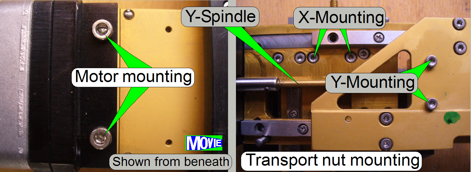
Dismount the carriage drive unit
·
Remove the transport nut mounting bolts from
the appropriate carriage.
 ·
Remove
the motor mounting bolts.
·
Remove
the motor mounting bolts.
·
Pull
the motor together with the entire carriage transport unit out of the carriage.
1.
Set the motor to Home1,2.
2.
Screw the transport nut onto the spindle some turns.
3.
Insert the carriage drive unit and check the position
of the transport nut in relation to the bolt drillings on the carriage; the
drillings of the carriage should fit the transport nut near to the negative
limit.
4.
Remove the transport unit and adjust the position of
the transport nut in relation to the carriage mounting more precise by using
half turns also.
5.
Set the motor to Home1,2.
6.
Insert the carriage transport unit, drive in the motor
mounting bolts and the transport nut mounting bolts and check the negative
limit; see also above “The limiters” and adjustment procedures “To find the
negative limit”. The negative limit is often found in the near of -800 steps
(but this is not a requirement).
7.
If the negative limit does not fit the requirements
(more then 1600 steps are possible in negative direction) remove the carriage
drive unit again and adjust the position of the transport nut in relation to
the spindle by using the next or previous start point of the thread; this way
the limit can be adjusted with an accuracy of 800 steps (a ¼ full turn)
and this fulfill the requirements always (this is done only, if the adjustment
by using half turns does not deliver the successful result).
8.
Repeat from step 4 until the requirements of the
negative limit are fulfilled.
9.
Check the positive limit; see also “Adjustment
procedures”.
10.
By loosening the motor mounting bolts and tighten them
in the correct motor position, the straightness of the drive unit can be found
and adjusted.