Adjust
magazine unit
For
technicians!
Contents
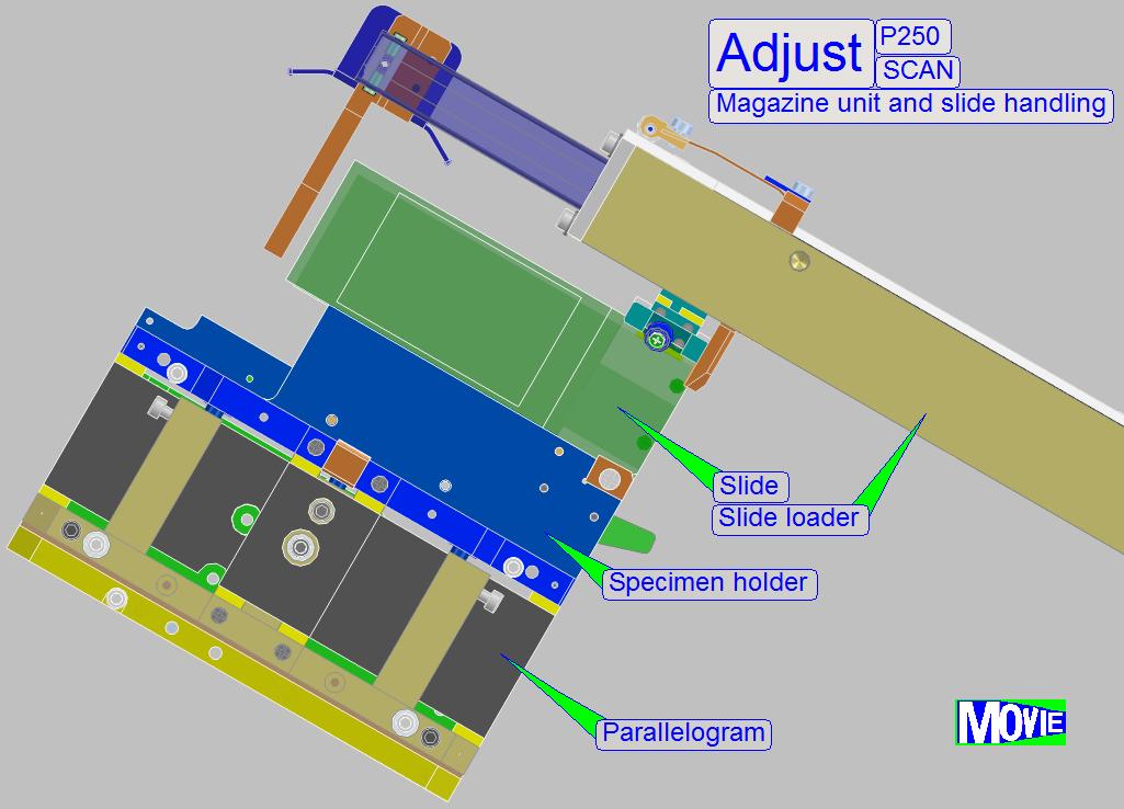
Adjust
the slide insert and removal action
Adjust the
magazine load mechanics
Magazine
load / unload test and slide insert / removal test
Adjust
slide insert and removal
Requirements after adjustment
The following procedures and checks are done to adjust all the components
of the magazine unit; the result should be:
- The slides with the specified
slide dimensions should be
inserted easily into the specimen holder, without any slide insert
difficulties.
- The slides with the specified slide dimensions should be hold in the
specimen holder correctly, the slide must not change its position during
slide scanning.
- The slides with the specified slide dimensions should be removed
easily from the specimen holder and placed return into the slide slot of
the magazine, without any slide removal difficulties.
- The magazines should be loaded from the input stack into the
magazine channel without stumble or magazine jamming.
- The magazine should move in the magazine channel easily; without
magazine jamming.
- The magazine should be moved from the magazine channel into the
output stack correctly, without magazine jamming.
- The magazine input stack sensor should show the state “Magazine
present”.
- The magazine output stack sensor should show the stat “Magazine
output stack full”.
- The magazine supporters should work correctly.
Checks
Before you are starting any scanner checks or adjustments, please check
the following conditions:
The magazine
The slide positions are clean and dry (no cover slip glue residues, no
dust and no glass shards can be found); otherwise clean the slide slots of the
magazine.
- The magazine,
used for the check and adjustment purposes should be cleaned by the use of
a brush and compressed air or canned aerosol cleaner.
The permanent magnet is present and works correctly together with the input and output
magazine stack sensor (check this
behavior with the service program).
The slide
The used slide(s) (of the user) fulfill the allowed slide dimensions.
The cover slip should not be less than 1.0mm from the slide edge; it
should be in distance from the slide holding mechanics of the specimen holder.
Labels or stickers should be found only on the barcode area, beside the
cover slip.
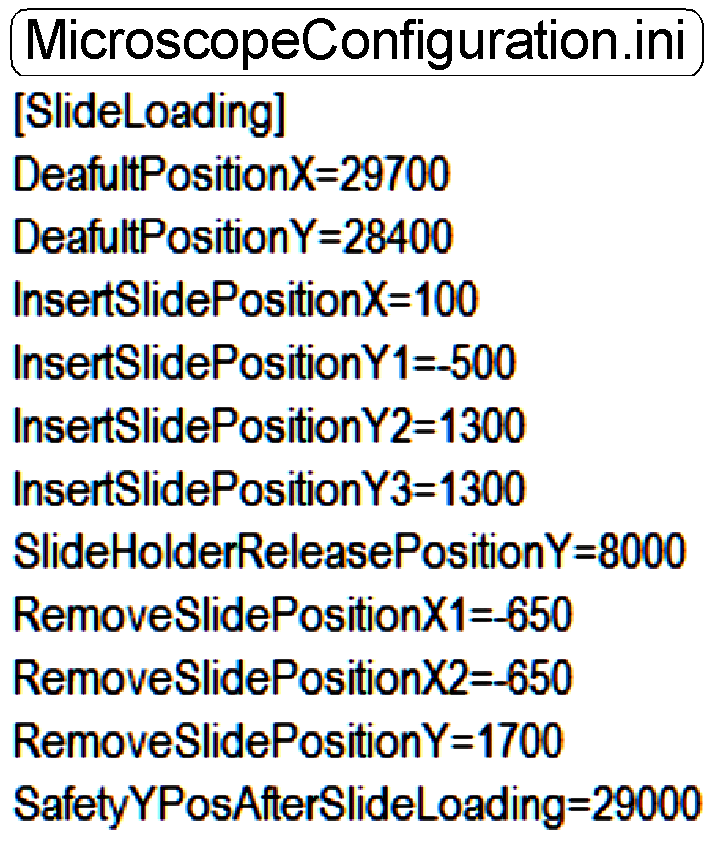
- Please make a security backup of the file
“Microscope
Configuration.ini”!
The
file “MicroscopeConfiguration.ini”
will be found in the folder:
In the software
version 1.14 (Windows XP): C:\DocumentsAndSettings\AllUsers\ApplicationData\3DHISTECH\SlideScanner\
In the software
version 1.15 (Windows 7): C:\ProgramData\3DHISTECH\SlideScanner\
In earlier software versions: Please
use the file search option of Windows and search for the file MicroscopeConfiguration.ini
or “Config.ini”.
· To edit the parameter values of the file
“MicroscopeConfiguration.ini” the program “WordPad” should be used.
· Save the file
“MicroscopeConfiguration.ini” without any formatting information, as a
*.txt-type file (text only)!
The following sequence is based on the adjustments of the new components (since
October, 2012; the specimen holder fixing fork, the slide leading spring and
the slide clamp lifter mechanics), but by replacing the appropriate procedure,
the other, earlier developed components can be adjusted as well by the use of
this sequence (the principle is the same).
- For checks, use the
appropriate values in the relevant section of the file “MicroscopeConfiguration.ini” of the scanner in
question!
1)  Check / define the hardware
limits of the X-Y-stage unit.
Check / define the hardware
limits of the X-Y-stage unit.
2) Check / adjust the magazine
unit position.
3) Check / adjust the position
and the size of the specimen holder fixing fork.
4) Check / adjust the magazine
position for the slide insert / removal operation.
5) Check / define the value of the parameter
“DefaultPositionX”.
6) Check / define the slide
insert position in X-direction; define “SlideInsertPositionX”.
7) Check / adjust the position
and the height of the inner finger.
8) Set the slide insert start position in Y-direction;
define “InsertSlidePositionY1”
9) Check / define the final
slide insert position in Y-direction.
10) Check / adjust the height
and the position of the slide clamp lifter.
11) Check / define the slide
removal position in Y-direction.
12) Check / define the slide
removal position “X1” in X-direction.
13) Check / define the slide
removal position “X2” in X-direction.
14) Check / adjust the magazine
load mechanics
15) Check the magazine load /
unload operation.
16) F inishing the adjustments
- Run the tests to check the magazine load / unload and
the slide insert / removal procedures
Check or define the
hardware limits of the X-Y-stage unit.
![]() “The
limiters” and “Important”
“The
limiters” and “Important”
Important
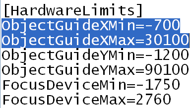
For
the following checks, use the values in the section [HardwareLimits] of the file “Microscope Configuration.ini” of the
scanner in question; the here shown
example values have not to be used!
Requirements
- During movements
of the specimen holder in X-Y-direction lost steps (not more than +-2
steps) have not to occur.
Check the hardware limits in X-direction
To check the negative limit in -X-direction
1.
 With the service program set the Y-carriage to
Home1,2.
With the service program set the Y-carriage to
Home1,2.
2. Set the X-carriage to Home1,2.
3. With the service program
go forward in direction of the negative limit to the X-motor position, defined
as value of the parameter “ObjectGuideXMin”; in the example on the right it would be 700 steps.
4. Go backward 700 steps.
5. Press Home1 (only). There should be not more than +-2 steps difference to Home1. If there are more steps lost, the negative limit is faulty, define / find the negative limit.
6. If there are not more than 2 steps difference to Home1, increase the number of steps by 100 steps.
7. With the new value (now 800 steps, in relation to the example) go in direction to the negative limit.
8. Go backward 800 steps in direction to Home1.
9. Press Home1 (only).
10. If there are more than +-2 steps lost, the limit position is found correctly; the appropriate limit must not be defined again.
To check the positive limit in +X-direction
11. With the service program set the Y-carriage to Home1,2.
12. Set the X-carriage to Home1,2.
13. With the service
program go forward to the X-motor position, defined as value of the parameter “ObjectGuideXMax” in the example on the right =30100 steps.
14. Go backward 30100 steps.
15. Press Home1 (only). There should be not more than +-2 steps difference to Home1. If there are more steps lost, the positive limit is faulty, define / find the positive limit.
16. If there are not more than 2 steps difference to Home1, increase the number of steps by 100 steps.
17. With the new value (now 30200 steps, in relation to the example) go in direction to the positive limit.
18. Go backward 30200 steps in direction to Home1.
19. Press Home1 (only).
20. If there are more than +-2 steps lost, the limit position is found correctly; the appropriate limit must not be defined again.
If the limit is
incorrect, Find the hardware
limits for the X-carriage
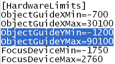
Check the hardware limits in Y-direction
·
Insert a slide into the specimen holder manually
To check the negative limit in
-Y-direction
21.
 With the service program set the Y-carriage to
Home1,2.
With the service program set the Y-carriage to
Home1,2.
22. Set the X-carriage to Home1,2.
23. Go forward to the position X=28000 steps.
24. With the service
program go forward to the Y-motor position, defined as value of the parameter “ObjectGuideYMin” in the example on the right =-1200 steps.
25. Go backward +1200 steps.
26. Press Home1 (only). There should be not more than +-2 steps difference to Home1. If there are more steps lost, the negative limit is faulty, define / find the negative limit.
27. If there are not more than 2 steps difference to Home1, increase the number of steps by 100 steps.
28. With the new value (now 1300 steps, in relation to the example) go in direction to the negative limit.
29. Go backward +800 steps in direction to Home1.
30. Press Home1 (only).
31. If there are more than +-2 steps lost, the limit position is found correctly; the appropriate limit must not be defined again.
To check the
positive limit in +Y-direction
32. With the service program set the Y-carriage to Home1,2.
33. Set the X-carriage to Home1,2.
34. Go forward to the position X=29000 steps.
35. With the service
program go forward to the Y-motor position, defined as value of the parameter “ObjectGuideYMax” in the example on the right =90100 steps.
36. Go backward 30100 steps.
37. Press Home1 (only). There should be not more than +-2 steps difference to Home1 and the focus pin should not touch the specimen holder! If there are more steps lost, the positive limit is faulty, define / find the positive limit.
38. If there are not more than 2 steps difference to Home1, increase the number of steps by 100 steps.
39. With the new value (now 30200 steps, in relation to the example) go in direction to the positive limit.
40. Go backward 30200 steps in direction to Home1.
41. Press Home1 (only).
42. If there is not more than +-2 steps lost, the limit position is found correctly; the appropriate limit must not be defined again.
Check the magazine unit position
Requirement
· 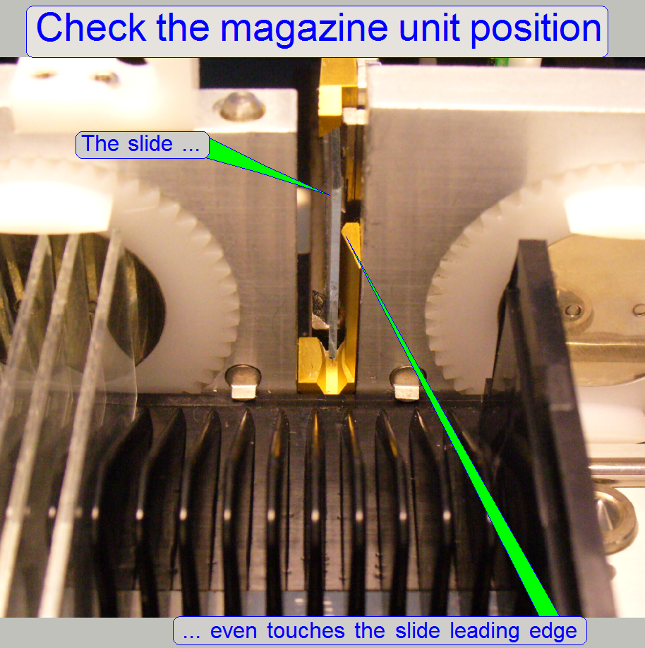 If the slide is pushed
from the specimen holder in direction to the slide leading edge (manually), the
slide leading edge should be even touched by the slide.
If the slide is pushed
from the specimen holder in direction to the slide leading edge (manually), the
slide leading edge should be even touched by the slide.
· If the slide leading edge will be hit or a gap
exists between slide and slide leading edge, adjustments are required.
- Insert a slide
manually into the
specimen holder.
1. Set the specimen holder to the positions Y-Home1,2
and X-Home1,2.
2. Shift the slide carefully backward (the specimen
holder has not to be moved in Z-direction), in direction to the magazine. The
slide should be a little bit higher than the slide leading slot bottom. If
required, move the X-stage some hundred steps in direction to the negative
limit, “ObjectGuideXMin”.
3. If the slide leading edge is not touched or the
slide will hit the slide leading edge:
a. The position of the magazine unit may be wrong and /
or
b. The position of the “Specimen holder fixing fork” is wrong.
4. Shift the slide return into the specimen holder so,
that a movement in the +X-direction can be performed.
5. Move the X-stage 28000 steps in plus (+) direction.
6. Loosen the “Specimen holder fixing fork” from beneath
until it becomes easily moveable.
7. Move the X-stage 28000 return to the previous
position. With this movement, the specimen holder fixing fork may move in
Z-direction as required; it will not fix the specimen holder in the wrong
position.
8. Now shift the slide again in direction to the slide
leading edge and check the behavior:
9. If the slide leading edge is not touched or the
slide will hit the slide leading edge:
10. The position of the magazine unit is wrong.
- Adjust the
position of the magazine unit first
- Adjust the
position of “The specimen holder fixing fork” next.
Adjust the
magazine unit position
The task
· 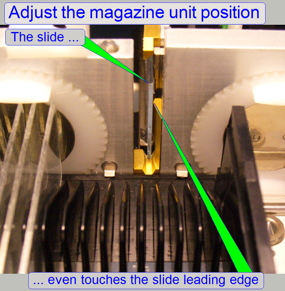 Adjust the
position of the magazine unit so, that the slide leading edge is even touched
by the slide if the slide is pushed from the specimen holder in direction to
the slide leading edge (manually).
Adjust the
position of the magazine unit so, that the slide leading edge is even touched
by the slide if the slide is pushed from the specimen holder in direction to
the slide leading edge (manually).
· If the slide leading edge will be hit or a gap
exists between slide and slide leading edge, adjustments are required.
![]() “Magazine unit mounting” and “Magazine unit position
adjustment”
“Magazine unit mounting” and “Magazine unit position
adjustment”
11. Set the specimen holder to the positions Y-Home1,2
and X-Home1,2.
12. Insert a slide manually into the specimen holder.
13. The slide should be a little bit higher than the
slide leading slot bottom. If required, move the X-stage in direction to the
negative limit, “ObjectGuideXMin”.
14. Move the X-stage 28000 steps in plus (+) direction.
15. Loosen the “Specimen holder fixing fork” until it
becomes easily moveable.
16. Move the X-stage 28000 steps return to the previous
position. With this movement, the specimen holder fixing fork may move in
Z-direction as required; it will not fix the specimen holder in the wrong
position.
17. Shift the slide carefully backward, in direction to
the slide leading slot; the specimen holder should not move in Z-direction;
otherwise repeat from step 13 logically.
18. If the slide leading edge is not touched or the
slide will hit the slide leading edge:
a. Loosen the magazine unit fixing bolts a little bit
until the magazine unit may be barely shifted on its mounting and
b. Drive the magazine unit position adjustment bolts as required.
19. Shift the slide return into the specimen holder so,
that a movement in the +X-direction can be performed.
20. Move the X-stage 28000 steps in plus (+) direction.
21. Move the X-stage 28000 return to the previous
position. With this movement, the specimen holder fixing fork may move in
Z-direction as required; it will not fix the specimen holder in the wrong
position.
22. Now shift the slide again in direction to the slide
leading edge and check the behavior:
23. If the slide leading edge is not touched or the
slide will hit the slide leading edge, repeat from step 18b.
24. If the slide even touches the slide leading edge
tighten the magazine unit fixing bolts and check the behavior again; repeat
from step 19 one time.
- If the position of the magazine unit is correct, adjust “Position of the
specimen holder fixing fork” next.
Position and the
size of the specimen holder fixing fork
The task
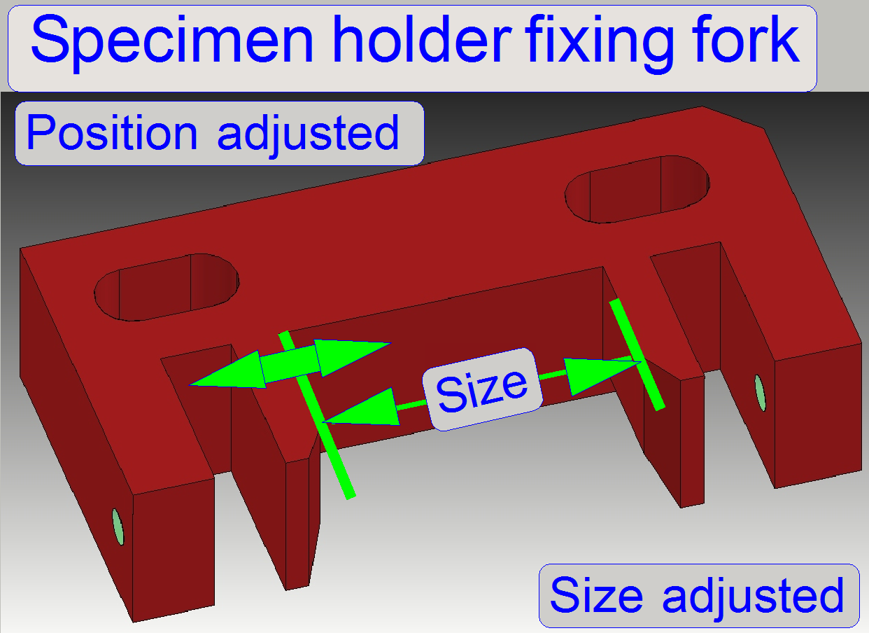 Adjust the position of the fixing fork so,
that the specimen holder is not pushed in Z-direction if the Y-stage moves
the specimen holder into the fork.
Adjust the position of the fixing fork so,
that the specimen holder is not pushed in Z-direction if the Y-stage moves
the specimen holder into the fork.- Adjust the size of the fork so, that
movement in Z-direction of the specimen holder is not possible but the specimen
holder moves easily in the fork it should not be pressed by the fork.
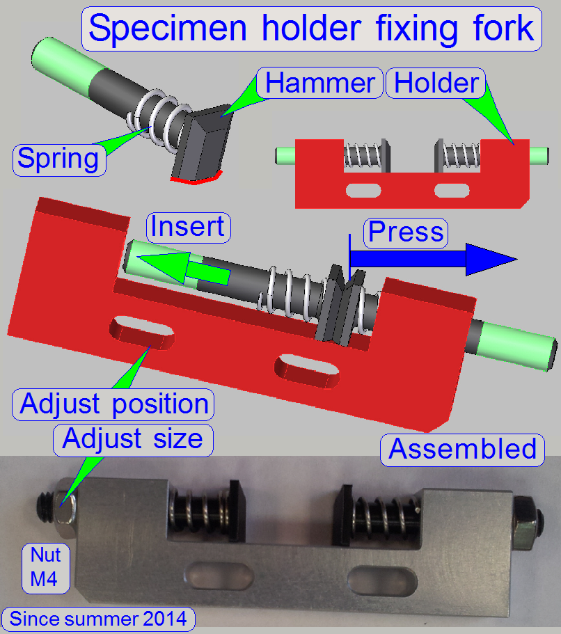
![]() The specimen holder fixing
fork
The specimen holder fixing
fork
Adjust the size of the specimen holder fixing fork
The size of the specimen holder fixing fork can be adjusted in a small
range by driving the size adjustment bolts.
The adjustment is correct, if:
- The specimen holder can not move in Z-direction during slide
insertion / removal and
- The specimen holder does not move strong; it is not be pressed by
the fork.
Adjust the position of
the specimen holder fixing fork
 The task
- Find the correct position of the specimen
holder fixing fork so, that the specimen holder right hand edge is in
plane with the slide leading edge and the parallelogram is not moved in
Y-direction.
- This adjustment assumes
that the magazine unit position is already adjusted correctly.
1. Move
the Y- and X-stage to the positions Home1,2.
2. Move
the X-stage to the position 28000 steps.
3. Move
the Y-stage to the position 88000 steps.
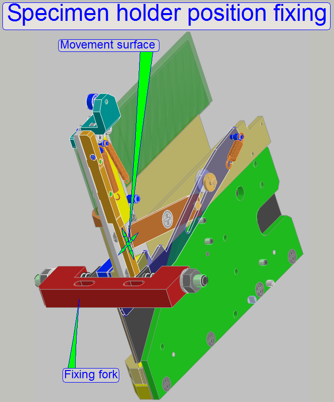
4. Loosen
the mounting bolts of the fixing fork from beneath.
5. Move
the Y-stage until the position Y=3200 steps is reached.
6. Move
the Y-stage backward in direction to Home1,2 by 100 steps until the the
movement surface will touch the fixing fork.
7. Fit
the fixing fork with the movement surface of the specimen holder and tighten
the mounting bolts of the fixing fork; please do not touch the specimen holder
during this action, it should not move in Z-direction!
8.  Check the adjustment by repeating this
sequence from the step 5. If the specimen holder movement surface touches the
fixing fork, no movements in Z-direction should be expired, otherwise repeat
from step 3.
Check the adjustment by repeating this
sequence from the step 5. If the specimen holder movement surface touches the
fixing fork, no movements in Z-direction should be expired, otherwise repeat
from step 3.
·
If the correct position of the fork is
found, check the plane of the slide leading edge and the specimen holder right hand edge again;
execute the steps logically as described in: check the magazine unit position!
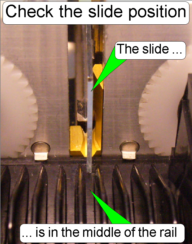
The task
- Adjust the slide
position of the magazine so, that the outer specimen finger is in the
middle of the slide slot of the magazine.
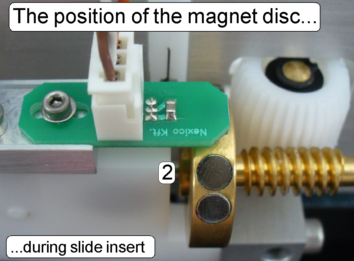
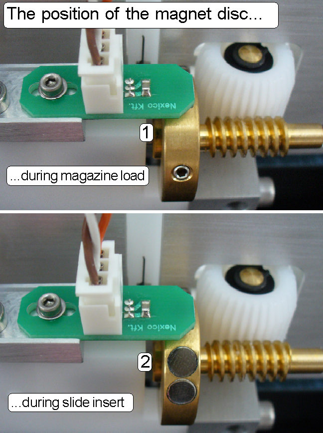
 The adjustment is done by positioning the “The magnet disc” on the feeder spindle.
The adjustment assumes, that the position of the magazine
unit and the position of the specimen
holder fixing fork is correct.
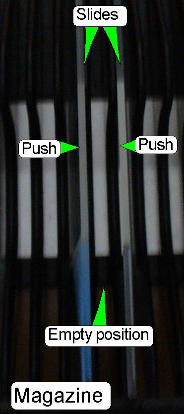
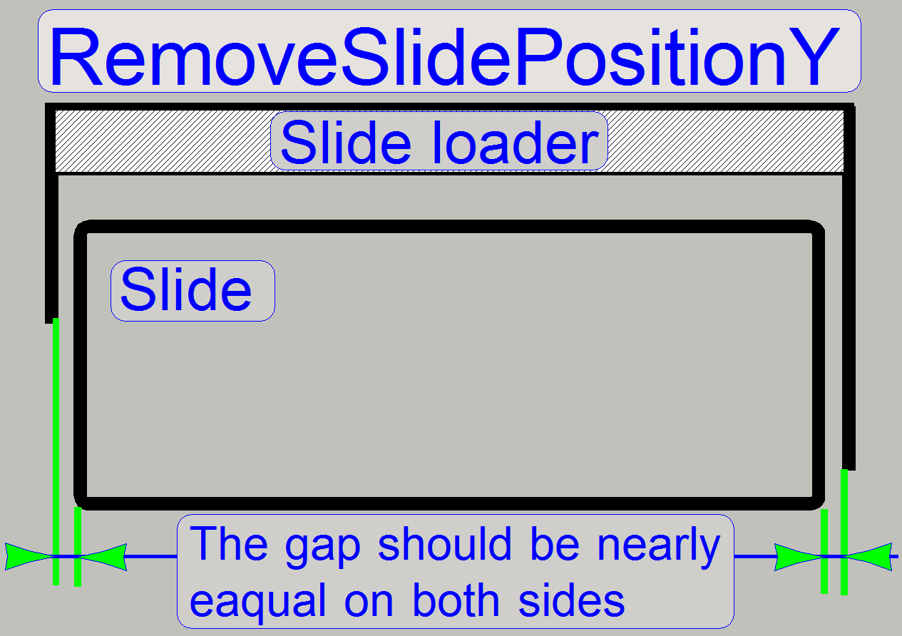
1. Insert a magazine manually or by
the use of the service program, prepared with two slides, nearly in the middle
of the magazine as shown on the right (“Magazine”).
3. With the
part “magazine feeder” of the service program move the magazine in the feeder
channel until the slide loader stays over the “empty position”, between the two
slides, and the stop position of the magnet disc is
“Stop forward”, the slide insert position.
4. Move
the slide loader moving part manually a little bit into the scanner until the
outer finger can be seen easily.
5. Push
the two slides toward the outer finger.
6. If the
gaps on both sides of the outer finger are not equal, memorize the “Stop
forward” position then rotate the magnet disc until the gaps are equal.
Memorize this position also.
7. Loosen
the magnet disc fixing and rotate the magnet disc by the difference of the two
memorized positions and tighten the fixing bolt.
8. With
the service program move the slide loader moving part into its outer end
position, rotate the feeder gear backward two turns, then rotate the feeder
gear forward until the empty position of the magazine is found again, the stop
position of the magnet disc is “Stop forward”.
9. Repeat
from step 4 until the gaps are equal on both sides.
If the adjustment
is finished, check the correctness of the found position by executing the
magazine load test. Check all the magazines without any slide in any magazine;
see also: “Check the magazine load procedure”.
Check the magazine load and unload procedure
The result should be
- All the empty magazines,
used with this scanner can be loaded from the input stack into the
magazine feeder channel without stumble; insert the magazines into the
input stack one by one!
- If not: Check the rack of the
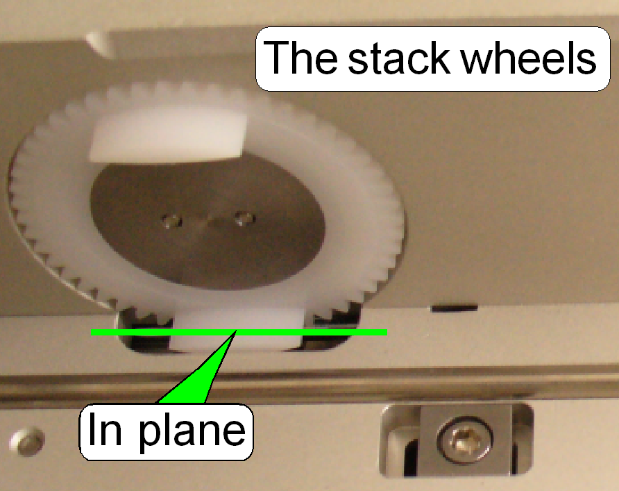
magazine in question.
- If more
magazines failed this test, adjust the slide insert position of the
magazine more precise.
- If more
magazines failed this test, check the smoothness of the side wall
surface in relation to the stack wheels, the stack wheels should be
about 0.1mm deeper as the surface of the side wall.
- The magazine (all 10
magazines in sequence), arrived onto the feeder rails, should be
recognized by the left magazine sensor and should be moved to the first
slide position.
- Now check the first
slide position visually, it should fit with the slide leading slot.
- By moving the magazine
to the magazine unload position, the unload position should be found
correctly and the magazine should be moved into the output stack evenly
and smoothly, without stumble.
- Check the correct
function of “The magazine supporters” also.
- If 9 magazines are
present in the output stack and the 10th magazine will be moved
into the output stack, the test program should send a message, that the
output stack is full.
Check this
behavior with the options “Magazine load” and “Magazine unload” of the service part of
the program “SlideScanner.exe”.
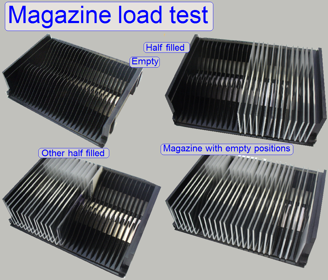
If the magazine
load / unload test with the empty magazines is finished, prepare some magazines
as follows:
- Fill the left side of a
magazine with 10 slides.
- Fill the right side of a
magazine with 10 slides.
- Fill an entire magazine
with slides (25 slides).
Check the smoothness
and the correctness of the magazine load procedure (without stumble) with the
options “Magazine load” and “Magazine unload” of the service part of the program “SlideScanner.exe”.
Define the value of the parameter “DeafultPositionX”
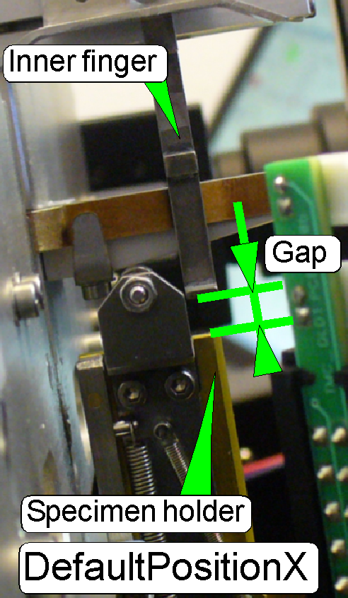 The
task
The
task
·
This value allows the movement of the
inner finger above the slide clamp / specimen holder if a slide was inserted and
the slide loader moves backward without slide after a slide insert procedure or
·
The slide loader moves inward, into the
scanner, before the real slide removal procedure will be executed.
·
In both movements of the slide loader, the
inner finger has not to hit the specimen holder / the slide clamp.
·
Check the value by inserting and removal
of the widest and thickest test slide manually (26.1mm wide and 1.20mm in
thickness).
Requirements
·
The hardware limit in the direction “Xmax”
has to be defined correctly.
DeafultPositionX
= ObjectGuideXMax – 100 steps.
Example
If the
hardware limit in +X-direction is found with “ObjectGuideXMax” = 29800 steps,
the value of the parameter “DeafultPositionX” will be 29700 steps.
- Update the value of the parameter
“DeafultPositionX” in the section [SlideLoading] of the file “Microscope
Configuration.ini” and save the file.
Remark
The value of the
parameter “DeafultPositionX” is not critical, but a gap between “Slide loader
inner finger” and the slide clamp / specimen holder has to exist, if the
specified movements are done.
Adjust the
slide insert position in X-direction
The task
 Define the value for the parameter
“InsertSlidePositionX” so, that the slide lower edge does not collide with
the lower edge of the specimen holder during slide insertion.
Define the value for the parameter
“InsertSlidePositionX” so, that the slide lower edge does not collide with
the lower edge of the specimen holder during slide insertion.- The widest and thickest allowed slide has
to be inserted smoothly also.
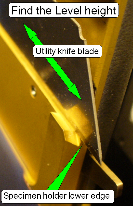
To reach this,
the “Level height” has to be found first.
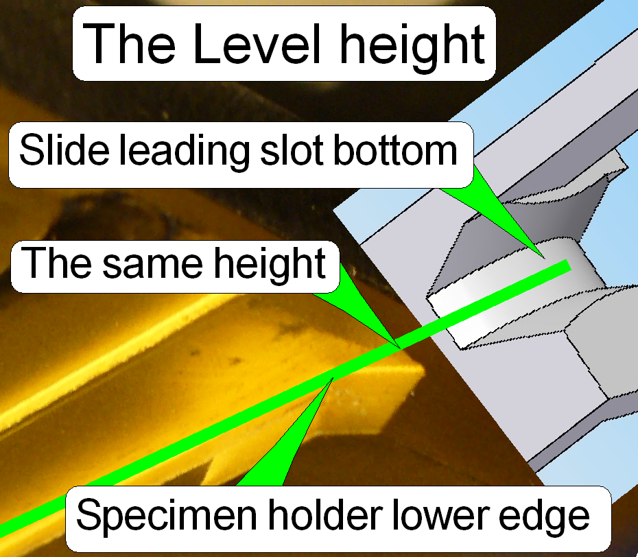
Level height: The “Level height” means the position in
motor steps of the X-direction where the specimen holder lower edge is in the
same height as the bottom of the slide leading slot.
·
Please notify the found value of the
“Level height”, it will be required again if the value of the parameter “RemoveSlidePositionX1” will be defined.
InsertSlidePositionX
= level height +600 steps +-100
steps
Because we are defining
the level height in an accuracy of 100 steps, the tolerance of +-100 steps may
occur.
1. Set
the positions Y-Home1,2 and X-Home1,2 of the X-Y-Stage.
2. Set
the focus position to -300 steps.
3. Set
the Y-direction to the value of the parameter InsertSlidePositionY1.
4. Remove
the slide loader and put a utility knife blade onto the lower edge of the
specimen holder.
5. Move
the blade in direction to the slide leading slot.
6. If the
blade hits the slide leading slot, move the X-stage in direction to the
negative limit by 100 steps and check the height again with the blade.
7. Repeat
the previous step until the specimen holder is in the same height as the slide
leading slot bottom.
8. If the
correct “Level height” is found, add to the actual number of steps in
X-direction 600 steps.
“SlideInsertPositionX”
= Level height + 600 steps.
Example: If the found Level height is -500 steps
(shown by the service program, X-direction step number), the value of the
parameter “SlideInsertPositionX” will be +100 steps.
9. Update
the value of the parameter “InsertSlidePositionX” in the section [SlideLoading]
of the file “MicroscopeConfiguration.ini” and save the file.
10. Check
the slide insert position with the widest and thickest slide; insert it with
the slide loader manually.
11. If the
slide lower edge hits the specimen holder lower edge, add to the value of the
parameter ‘InsertSlidePositionX’ 100 steps.
12. If the
thickest and widest slide will be inserted strong (the slide clamp has no gap),
reduce the value of the parameter ‘InsertSlidePositionX’ by 100 steps.
·
![]() “Adjust the slide clamp lifter position”
“Adjust the slide clamp lifter position”
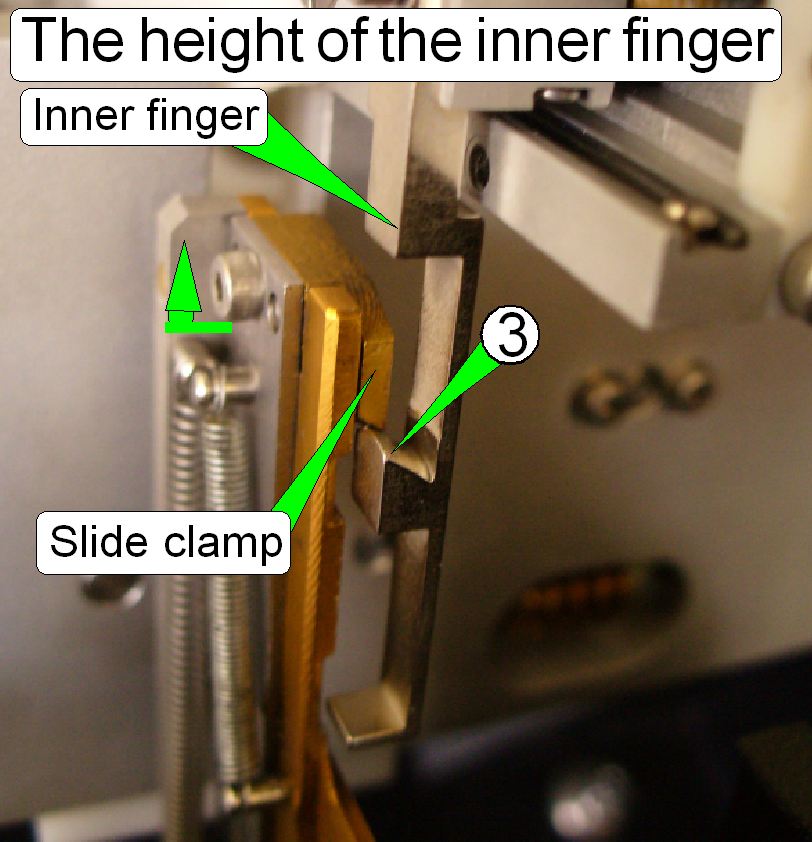
Position and height of the
inner finger
Requirement
- This adjustment assumes
that the value of the parameter “InsertSlidePositionX” is found correctly.
- “The position of the
magazine unit” and “The position of
the specimen holder fixing fork” is found
correctly.
The task
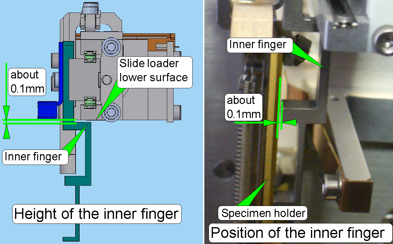 If the moving
part of the slide loader is moved from the position over the magazine into
the specimen holder or vice versa, the right hand edge of the inner
finger should pass the specimen holder without hitting it, otherwise,
the gap should be not more than 0.1mm.
If the moving
part of the slide loader is moved from the position over the magazine into
the specimen holder or vice versa, the right hand edge of the inner
finger should pass the specimen holder without hitting it, otherwise,
the gap should be not more than 0.1mm.- Adjust the height of the inner finger in relation to
the slide loader lower surface so, that the surface can be passed safely,
otherwise, the gap should not be more than 0.2mm.
Height of the inner finger
- Loosen the mounting bolt of the inner finger and adjust the height
as shown on the right.
- Check the correct height by moving the slide loader moving part
manually.
![]() Check / define the value of the
parameter “DefaultPositionX”
Check / define the value of the
parameter “DefaultPositionX”
Position of the inner finger
The position of the inner finger in relation to the edge of the specimen
holder is adjusted by the use of a fitting plate, situated on the mounting surface
of the inner finger; this adjustment is mostly not done in the field!
If the inner finger hits the edge of the specimen holder or if the gap is
too much, please check the position of the
magazine unit and check also
the correct position of the specimen holder fixing
fork first.
![]() “Check the magazine unit position”
and “The position of the specimen
holder fixing fork”.
“Check the magazine unit position”
and “The position of the specimen
holder fixing fork”.
Adjust the inner finger
vertical position
 This adjustment assumes that the value of
the parameter “InsertSlidePositionX” is found correctly.
This adjustment assumes that the value of
the parameter “InsertSlidePositionX” is found correctly.
- Set the positions
Y-Home1,2 and X-Home1,2 of the X-Y-Stage.
- Set the focus position
to -300 steps.
- Set the Y-direction to
the value of the parameter InsertSlidePositionY1 (400 steps).
- Set the X-stage to the
value of the parameter “InsertSlidePositionX” and move the slide loader
nearly into the middle of the slide clamp.
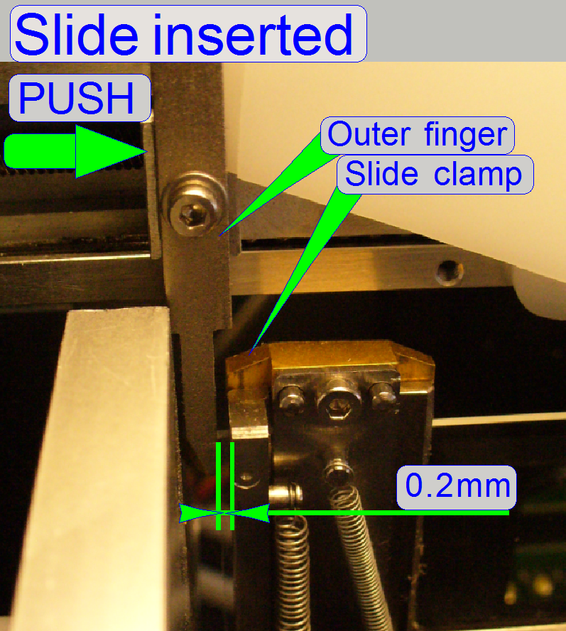
- Pull the slide clamp
carefully upward and check so the gap; it should be 0.2mm only.
- Move the inner finger
along the slide clamp and check this behavior in different positions.
- If there is no gap in
any position or the gap is too much, the position of the inner finger
should be adjusted. By loosening the mounting bolt of the slide loaders
inner finger, its position can be adjusted.
- If the mounting bolt of
the slide loaders inner finger is tightened again and only a small gap
exists (see step 6), move the widest and thickest allowed slide into the
specimen holder manually by the help of the slide loader and check the
gap again.
- The adjustment is
correct if the X-stage is in the position “InsertSlidePositionX” and the
widest and thickest allowed slide can be moved from the magazine into the specimen holder (by the
help of the slide loader, moved manually) without feeling a resistance if
the lower edge of the specimen holder is reached. If the slide inner edge
passed the slide clamp a small gap can be expired if the slide clamp is
carefully pulled upward!
- If the value of the
parameter “InsertSlidePositionX” was modified, the height of the inner finger has to be checked /
adjusted again!
Set the slide insert position in Y-direction; define
“InsertSlidePositionY1”
Requirements
- The hardware limit “ObjectGuideYMin” ≤ -500
steps.
The task
- Set the start position
for the slide insert procedure in Y-direction.
InsertSlidePositionY1 =
-500 steps
Remark
This position is
not critical. In earlier delivered systems this value was 400 steps by default.
Please, use now always the value of -500 steps, if possible.
Update the value of the parameter
“InsertSlidePositionY1” in the section [SlideLoading] of the file
“MicroscopeConfiguration.ini” and save the file.
Adjust the final insert
position in Y-direction
Requirements
- “InsertSlidePositionY1” ≤
“InsertSlidePositionY2,3”
The task
 Set the value for the parameters
“InsertSlidePositionY2” and “InsertSlidePositionY3” (often named as “InsertSlidePositionY2,3”)
so, that the specimen holder is never touched during slide insertion. Remember,
that both parameters must have always the same value!
Set the value for the parameters
“InsertSlidePositionY2” and “InsertSlidePositionY3” (often named as “InsertSlidePositionY2,3”)
so, that the specimen holder is never touched during slide insertion. Remember,
that both parameters must have always the same value!
1. Set
the positions Y-Home1,2 and X-Home1,2 of the X-Y-Stage.
2. Set
the X-direction to the value of the parameter InsertSlidePositionX.
3. Set
the Y-direction to the value of the parameter InsertSlidePositionY1 (nominal
=-500 steps).
4. Push
the slide loader moveable part manually, until the slide clamp of the specimen
holder is reached by the outer finger.
5. Adjust
the specimen holder Y-position (service program, Y-direction) so, that the
outer finger of the slide loader has a gap of about 0.2mm to the slide clamp of
the specimen holder and the slide loader moveable part is fully pushed into the
specimen holder. An accuracy of 100 steps is enough.
6. The
right value for the parameters “InsertSlidePositionY2,3” is found if the slide
loader is fully pushed into the specimen holder (check this behavior manually)
and a minimal gap exists between slide loader outer finger and slide clamp of
the specimen holder. If the gap is too much, the slide might touch the side
wall of the magazine channel.
7. Update
the value of the parameters “InsertSlidePositionY2” and “InsertSlidePositionY3”
in the section [SlideLoading] of the file “Microscope Configuration.ini” with
the same value and save the file.
Define the value of the parameter “RemoveSlidePositionY”
 Add six hundred steps to the value of the
parameter “InsertSlidePositionY2”.
Add six hundred steps to the value of the
parameter “InsertSlidePositionY2”.
RemoveSlidePositionY = InsertSlidePositionY2
+ 600 steps
Update
the value of the parameter “RemoveSlidePositionY” in the section [SlideLoading]
of the file “MicroscopeConfiguration.ini” and save the file.
Define the value of the parameter
“RemoveSlidePositionX1”
“RemoveSlidePositionX1”
= “Level height” -150
steps.
See also: Adjust the slide insert
position in X-direction
Update the value
of the parameter “RemoveSlidePositionX1” in the section [SlideLoading] of the
file “Microscope Configuration.ini” and save the file.
If the slide clamp
lifter is
mounted:
“RemoveSlidePositionX1 = level height -150
steps.
Update the value
of the parameter “RemoveSlidePositionX1” in the section [SlideLoading] of the
file “Microscope Configuration.ini” and save the file.
Define the value of the parameter
“RemoveSlidePositionX2”
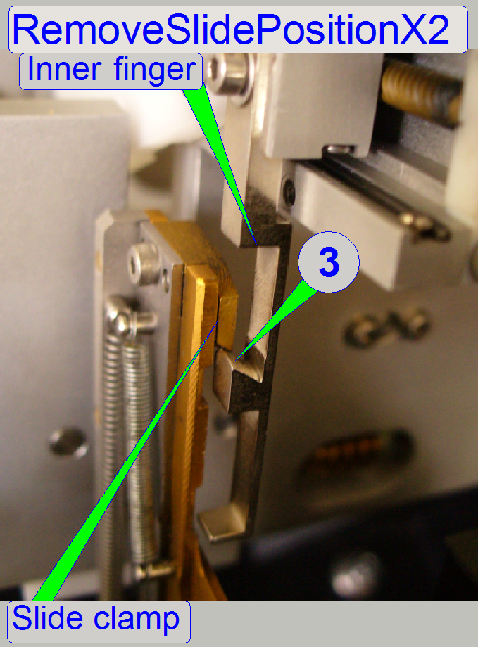 There are two possibilities to define the value
of the parameter “RemoveSlidePositionX2”,
depending on the used type of the inner finger.
There are two possibilities to define the value
of the parameter “RemoveSlidePositionX2”,
depending on the used type of the inner finger.
If the earlier developed inner finger type
is present:
1. Define the value
for the parameter “RemoveSlidePositionX2” so, that the edge (3) of the inner finger
(or the runway of the slide clamp lifter) passes the slide clamp easily, if no
slide is inserted and the slide loader moves backward.
2. Update the value
of the parameter “RemoveSlidePositionX2” in the section [SlideLoading] of the
file “MicroscopeConfiguration.ini” and save the file.
If the newer inner finger type (since
October, 2012, with slide clamp lifter) is present:
The values of the
parameters “RemoveSlidePositionX1” and
“RemoveSlidePositionX2” are identical.
Set: Value of “RemoveSlidePositionX2” = Value of
“RemoveSlidePositionX1”
Update the value
of the parameter “RemoveSlidePositionX2” in the section [SlideLoading] of the
file “MicroscopeConfiguration.ini” and save the file.
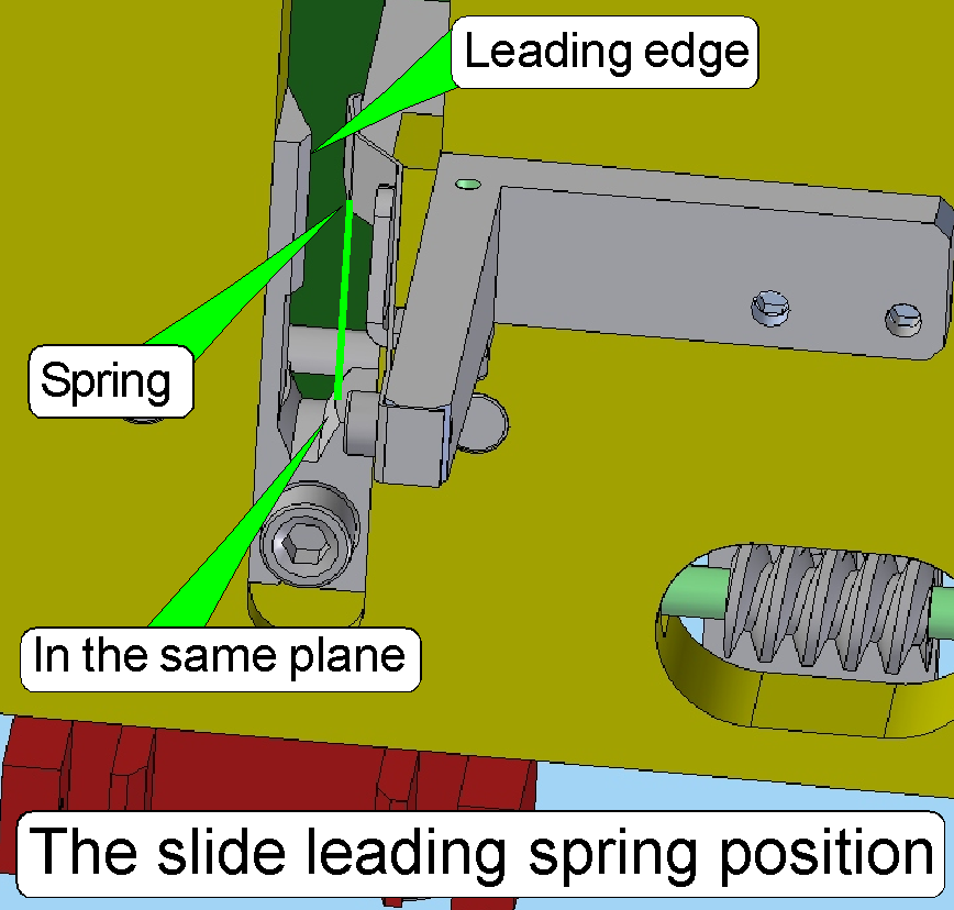
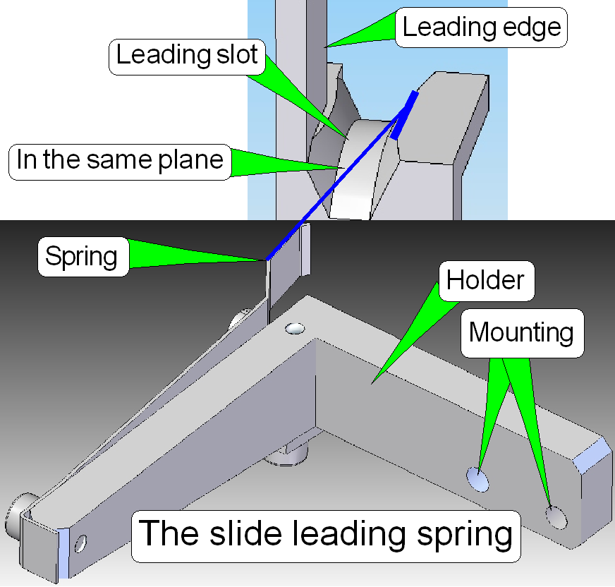 Check the position of the slide leading spring
The slide leading
spring should be in the same plane as the slide leading slot edge, in opposite
of the slide leading edge as shown.
The distance of
the leading spring surface to the slide leading edge is about
- If the thickest allowed slide with cover slip will be inserted, the spring should not touch the
cover slip!
Adjust the slide clamp lifter position
 This adjustment assumes that the value of
the parameter “InsertSlidePositionX” is defined correctly.
This adjustment assumes that the value of
the parameter “InsertSlidePositionX” is defined correctly.
As discussed
above, the slide clamp lifter opens
the slide clamp
during slide insertion.
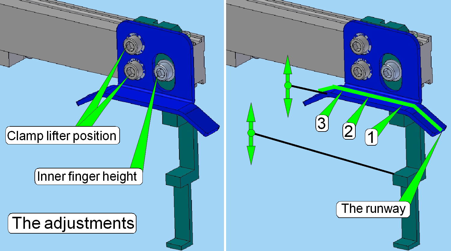
Adjust the
position of the slide clamp lifter so, that the slide clamp is
fully opened during insertion of the thickest and widest slide but
the specimen holder should not be pulled upward. Therefore, a small movement
upward (about 0.1 … 0.2mm) of the slide clamp should be possible in the
positions 1, 2 and 3 of the runway.
1. Insert
the thickest and widest slide manually.
2. Move
the slide loader manually in the direction of the specimen holder until the
linear part of the clamp lifter is reached (1) and the slide inner edge stays
over the slide fixing ball bearing.
3. Loosen
the clamp lifter mounting bolts and adjust the position of the clamp lifter so,
that the the slide fixing ball bearing is
even not touched by the slide (a gap of about 0.1mm) exists and the slide
should not falling out, then tighten the clamp lifter bolts.
4. Move
the slide loader manually to the middle (2) and the end (3) of the linear part
of the slide clamp lifter’s runway and check the gap in these positions also.
5. Check
in all three positions the gap of the “Lifter ball bearing in relation to the
run way of the slide clamp lifter; a gap of at least 0.1 … 0.2mm is required,
so the straining of the specimen holder and the parallelogram can be avoided.
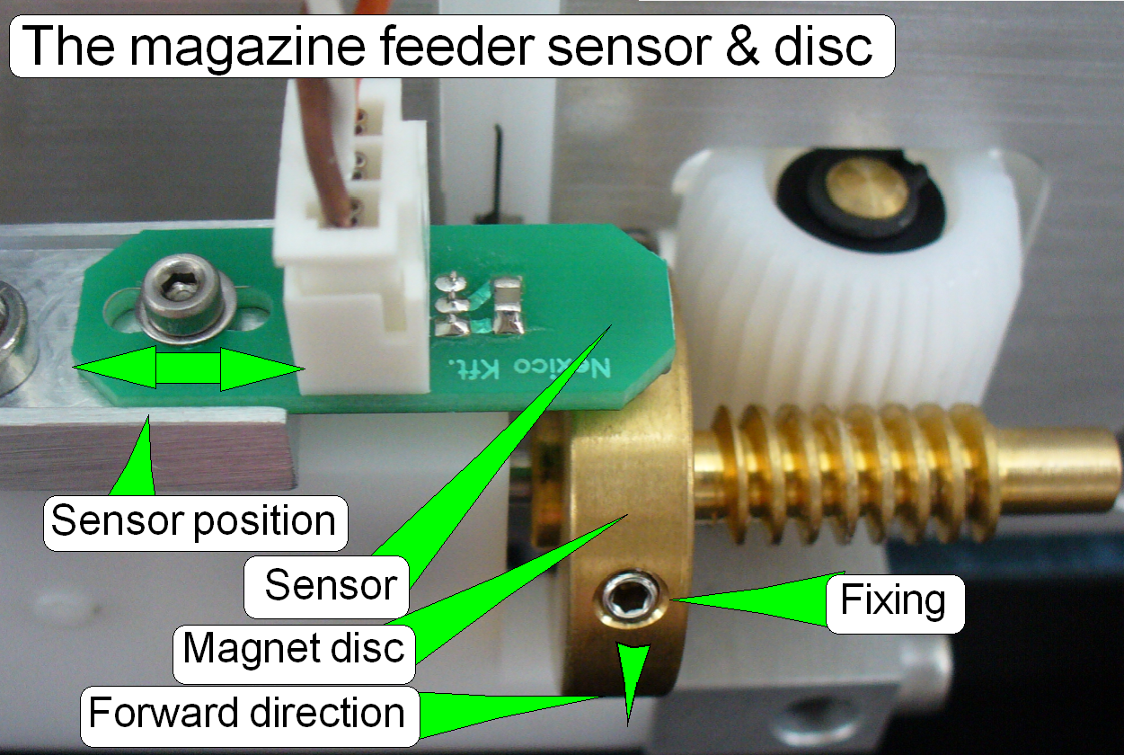
To adjust the
magnet disc position in relation to the spindle / magazine position, the fixing
must be loosened.
To reach the
correct stop position of the magnet disc use the rising edge of the sensor action.
The magnet disc
position is in connection with two actions, both depending on the right
adjustment:
1.
The magazine load action
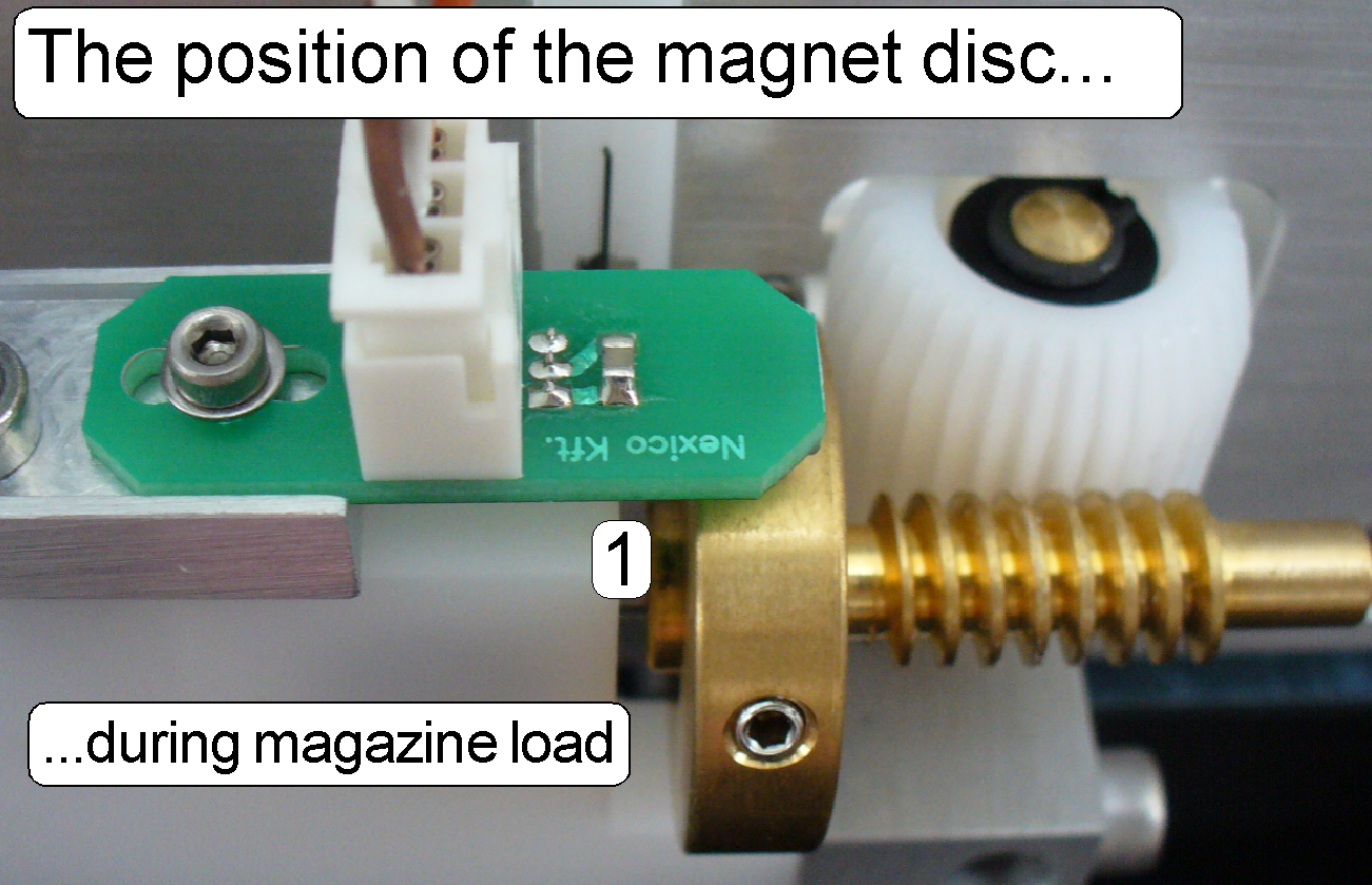
The
position of the cogs of the magazine rack and the cogs of the left sided feeder
wheel should allow the cogs to match up; so the magazine can move downward
smoothly and evenly. If the magazine arrived onto the feeder rails, and the
magnet disc is in the stop forward position (slide insert position) the left magazine (input) sensor
should be pressed. The correct start position of the magnet disc for the
magazine load procedure is found by rotating the magazine feeder gear backward
until the position “Stop
backward” is reached (with the service program); see
also (1) on the right.
2.
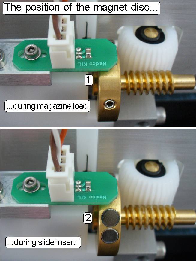 The slide insert / removal action
The
correct magazine position for the slide insert / removal action is also found
by adjusting the “Magnet disc” position. The slide loader outer finger should
be in the middle of the magazine rail. The correct position of the magnet disc
for the slide load procedure is found by rotating the magazine feeder gear forward
until the position “Stop forward”
is reached (with the service program); see
also (2) on the right.
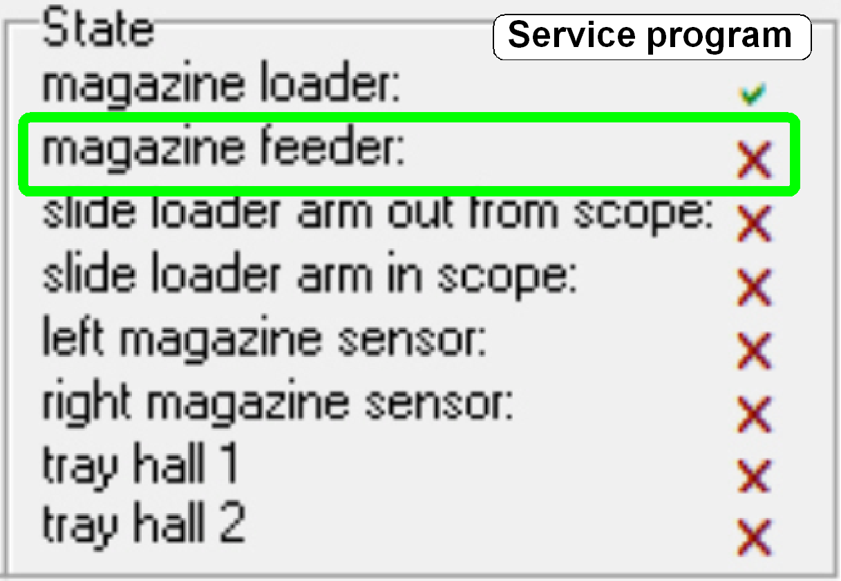
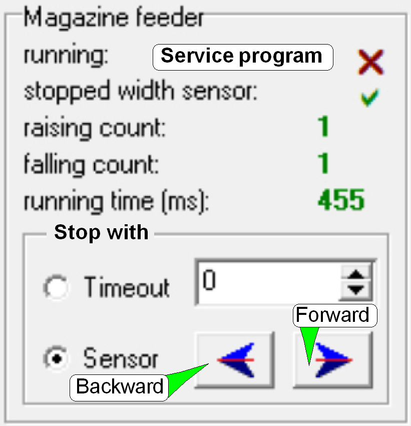
The magnet disc
stop position should be anywhere behind the second magnet and the sensor
should not signal (SlideScannerService.exe, DC controller, Sensor state,
Magazine feeder= X). It is important that after each turn of the feeder
spindle, the stop position of the disc should be always the same, if the option
“Stop with sensor” is selected. To reach this requirement, the position of the
sensor in relation to the magnet disc can be adjusted in a small range.
The detailed
adjustment procedure is described later.
- The magnet disc and the
sensor do not need maintenance.
1. If the
program SlideScanner.exe starts up, the following actions are done:
a. The
slide loader is moved backward, to the outer fixing position.
b. The
feeder gear had done at least one turn backward; the magnet disc stays in the
magazine load position (“Stop backward”); see also “The magnet disc”.
2. The
magazine load procedure is started via SlideScanner.exe (or the service
program) with the button “Load Magazine”.
3. The
magazine load motor and the input stack wheels are driven forward and the
magazine moves downward to the magazine feeder rails. At the same time, the
magazine (if any) is moved from the feeder channel to the output stack.
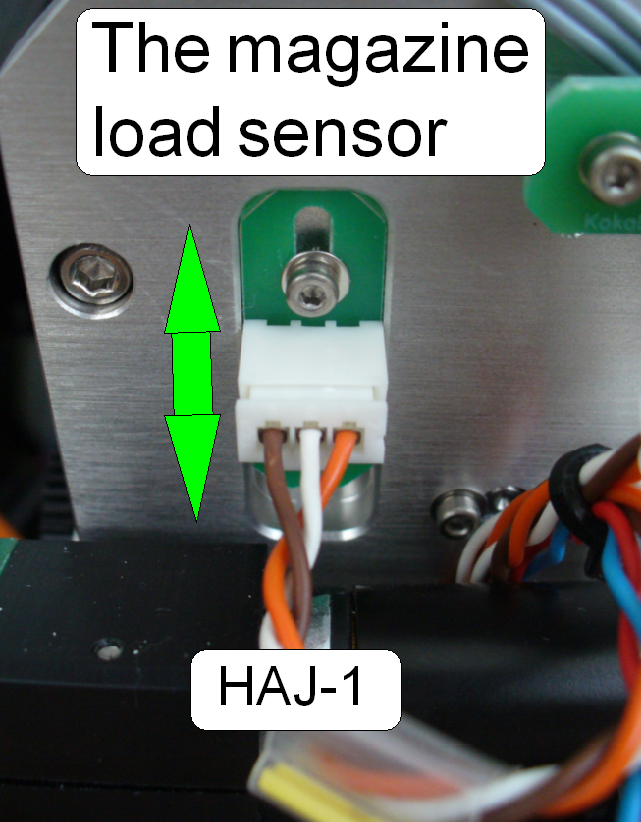
4. If the
magazine input stack wheels have done a half revolution, the magazine load sensor will
be attached and the software will switch off the magazine load motor.
5.
The magazine
input sensor may be pressed or not, the software changes the position of the magnet disc from “Stop backward” to “Stop forward” first, before
the state of the magazine input sensor is checked!
If the magazine
input sensor (“Left magazine sensor”) stays attached, the magazine will be feed
to the first slide load position.
If the magazine
input sensor stays released, the state “Magazine not present” will be detected
and all further operations are aborted.
6. Now
the magazine is moved to the actual slide position,
shown by the slide position selector of the SlideScanner.exe.
7. If the
last slide to be scanned had been removed into the magazine, the magazine
feeder gear moves the magazine to the right (forward), until the magazine
output sensor was released.
8. The
software counts the pulses of the magnet disc of the magazine feeder and checks
always the state of the right hand sensor (Magazine output sensor).
9. If the
state of the magazine output sensor is released, a turn backward (the magazine
moves to the left) follows and the magazine output sensor is checked again.
10. If the
sensor is pressed, the magazine load motor is started, the output stack wheels
rotates for a half turn and moving so the magazine into the output stack; in
the same time the next magazine (if any exists) is moved from the input stack
onto the feeder rails.
11. After
the feeder gear reached the position “Stop forward”, the software checks the
magazine input sensor (left magazine sensor). If it is not attached (see also
the part “The Magazine input sensor”),
the magazine load / unload procedure is finished; otherwise go to step 6 of the
“magazine load procedure”.
Adjust magazine load mechanics
1. 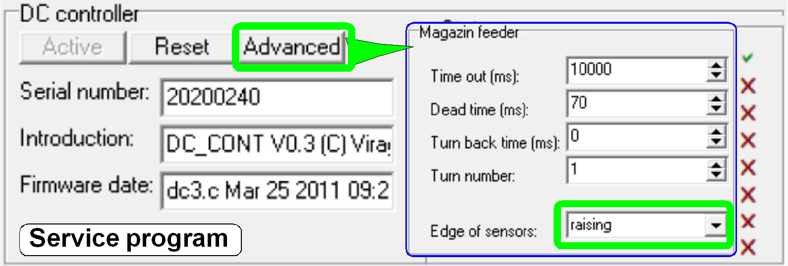 Start the service program
SlideScannerService.exe and switch active the section “Low level service” and
“DC controller”.
Start the service program
SlideScannerService.exe and switch active the section “Low level service” and
“DC controller”.
2. In the
tab „Advanced”, section “Magazine feeder” check / select the “Edge of the
sensor” for / to the option “raising”
and close the dialogue “Advanced” with OK!
- In opposite to the SCAN
3. 
 With
the “Magazine feeder” backward button the feeder gear brings the magnet disc
into the start position for the magazine load operation (1).
With
the “Magazine feeder” backward button the feeder gear brings the magnet disc
into the start position for the magazine load operation (1).
4. 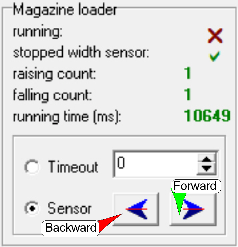 With the “Magazine loader” forward button and
no magazine in the input stack, bring the magazine input and output stack
wheels into the start position.
With the “Magazine loader” forward button and
no magazine in the input stack, bring the magazine input and output stack
wheels into the start position.
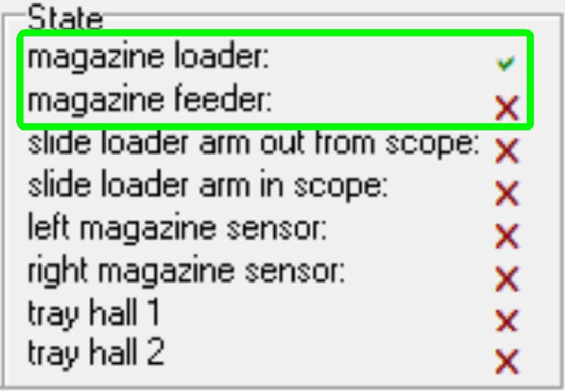
5. Check
the “Magazine loader” sensor state and the “Magazine Feeder” sensor state, the loader
state should be attached, during the feeder state should be released.
6. Check
the stop position of the input and output stack wheels.
7. The
stop position of the stack wheels should be perpendicular, and in plane with
the magazine channel bottom plate.
8.  Adjust the magazine loader sensor position
so, that this requirement (step 7) is reached, it is not a critical adjustment;
repeat steps 3 to 7 until the requirements are fulfilled.
Adjust the magazine loader sensor position
so, that this requirement (step 7) is reached, it is not a critical adjustment;
repeat steps 3 to 7 until the requirements are fulfilled.
9. Insert
a magazine into the input stack and with the “Magazine loader” forward button
start a magazine load. The magazine should move smoothly and evenly downward,
without stumble.
10.  If stumble occurs, the magazine feeder
gear should be adjusted via the magnet disc so,
that the cogs of the feeder wheel and the magazine rack engages and do not
disturb each other.
If stumble occurs, the magazine feeder
gear should be adjusted via the magnet disc so,
that the cogs of the feeder wheel and the magazine rack engages and do not
disturb each other.
11. If the magazine arrives onto the feeder rails and the magnet disc
position had been changed from backward to forward (from the magazine load
position to the slide load position), the magazine input sensor should be
pressed (see also “The magazine input
sensor”).
12. Adjust the position of the magnet disc so, that the magazine input
sensor is even pressed if the magnet disc had changed from “Stop backward” to
“Stop forward” (check the action with the shown sensor state (the left magazine
sensor) in the service program!).
13. Repeat the steps 7 to 9 several times and with different magazines. If
the requirements are fulfilled (no stumble during magazine load action and step
11 is fulfilled), the adjustment is finished.
14. Finally test the magazine load and unload procedure with all the 10
magazines, without slides. Observe the load procedure, the empty magazines
should move downward smoothly and evenly and the magazine sensor should be pressed, if the magazine arrives onto the feeder rails and
the slide insert position of the magnet disc is found (2).
 We assume the test “Check the magazine load /
unload operation” is already finished correctly.
We assume the test “Check the magazine load /
unload operation” is already finished correctly.
Finally test the
slide insert and removal actions with all the delivered magazines and different
slide sizes and slide shapes. This test should include the thinnest, thickest,
smallest and largest allowed (metal) slides. Test the slide insert / removal
action also in magazine slide positions without slide.
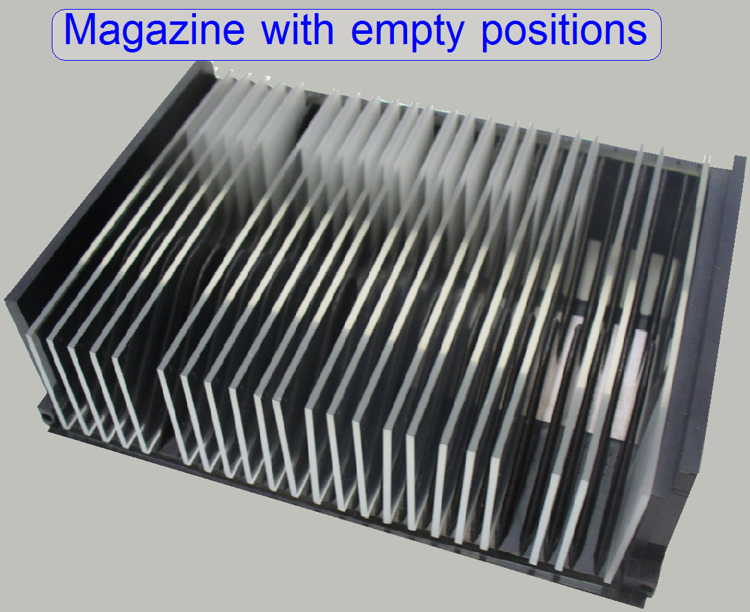
Prepare the magazines for the test
Meanwhile the slide loading test is in progress, check the following
actions visually
1.  During the magazine load action the
magazines moving downward smoothly and evenly.
During the magazine load action the
magazines moving downward smoothly and evenly.
2. The magazine
input sensor is attached the magazine is moved to the first slide position (see
also the chapter “The magazine input sensor”).
During
slide insertion
3. The slide
is inserted smoothly and evenly, without bangs and stronger (more force
requiring) sound, even if the thickest slides with the maximal width of 26.00mm
are inserted.
4. The
smallest slides should be hold correctly.
5. The
outer finger does not touch the slide clamp of the specimen holder if the slide
is fully inserted.
6. If the
slide loader moves backward the upper part of the slide clamp is not touched,
even if slides with the maximal width of 26.00mm are inserted.
During
slide removal:
7. The inner
finger crosses the slide clamp if there was an empty position in the magazine.
Magazine load and unload
test and the slide insert and removal test
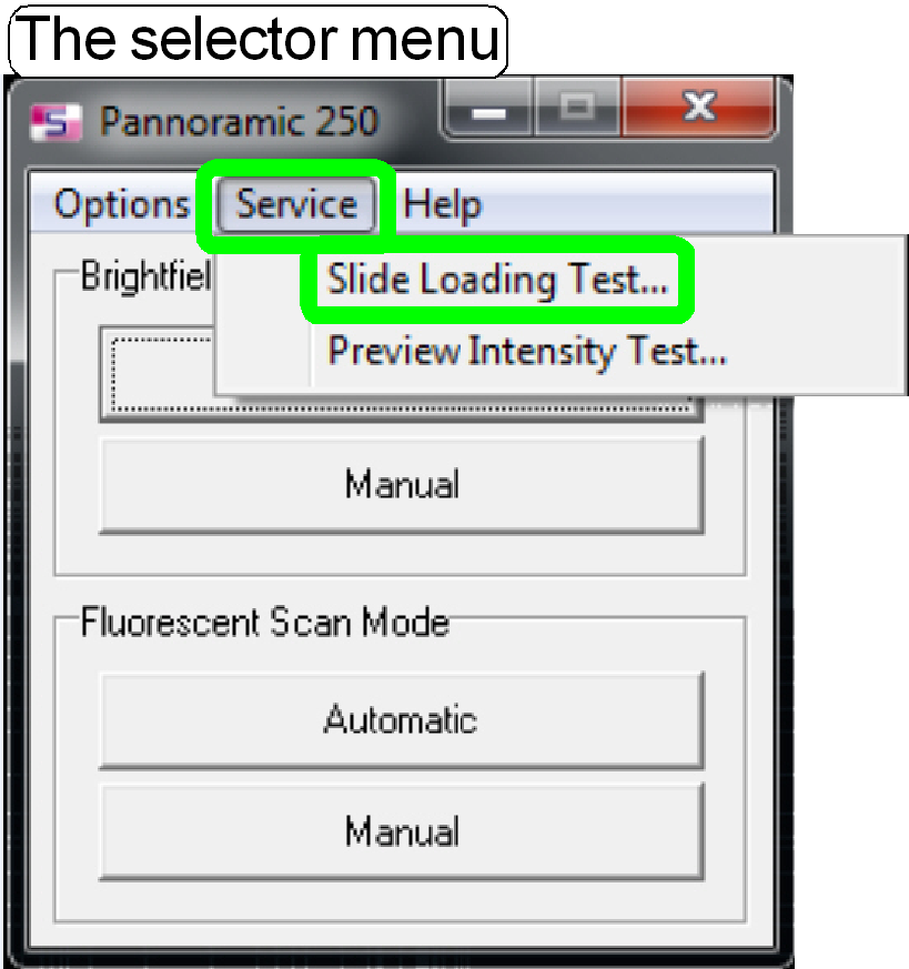
Start the program “SlideScanner.exe” with the service
password; the menu “Service” appears.
Select the option “Service” and “Slide loading test”;
the combined “magazine load / unload” (1, 2) and the slide insert / removal (3,
4) test will be selectable.
·
Insert one or more magazine(s) into the
input stack.
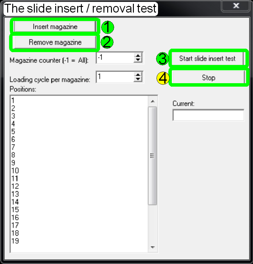
Magazine
load and unload test
By pressing the button “Insert magazine” (1) the magazine is moved from the magazine input
stack into the magazine feeder channel and if the magazine is detected by the
left magazine sensor, the magazine is moved to the first slide position of the
magazine.
By pressing the button “Remove magazine” (2) the magazine is moved in direction to the
output stack until the right magazine sensor is even passed, the sensor is in
the released state.
The magazine feeder motor rotated the magnet disc one
turn backward and checks the right magazine sensor again. If the right magazine
sensor is attached, the magazine unload position is found and the magazine is
moved into the output stack.
By pressing the button “Slide insert test” (3)
1.
If no magazine is present in the feeder
channel:
The magazine load
procedure is executed as described above (1).
The slides will
be inserted into the specimen holder and a few seconds later it will be removed
into the magazine.
If all (selected)
slides of the magazine passed the slide insert / removal procedure, the
magazine is feed to the output stack; see (2) above and the next magazine with
slides will be loaded. The procedure will be repeated until magazines are
present in the input stack or if the button “Stop test” (4) is pressed.
2.
If a magazine is already present in the
magazine feeder channel:
The magazine is
moved until the first slide position of the magazine is reached and then the
slide loading procedure is executed.
If the button “Stop
test” (4) is pressed, the test stops only, if the actual slide insert /
removal action is finished.
In emergency conditions, the switch “Emergency power
off” should be switched off.
Positions:
In the table “Positions” slide positions of the
magazine can be disabled from the slide insert / removal procedure by easily
deleting the appropriate line from the table.