Magazine unit, Slide handling; P250
For technicians and partly for sales managers!
These instructions
describe the procedures to install and adjust the magazine unit for Pannoramic
250 scanners. To help resolve problems with the magazine unit or problems with
slide insertion or removal a hardware description of the used components and
adjustment procedures are added.
The description is based on the software version 1.15 implemented
modifications are also described
Contents
Enhancements
in the magazine unit of the P250
Adjust
magazine load mechanics
Remove
or mount the slide loader
Adjust
the magazine load mechanics
Slide
insert and removal (software)
Full
adjustment of the magazine unit
Magazine
load and unload test and slide insert and removal test
List
of Parameters and explanation
For
safety regulations regarding human health and scanner functionality please
refer to: Precautions
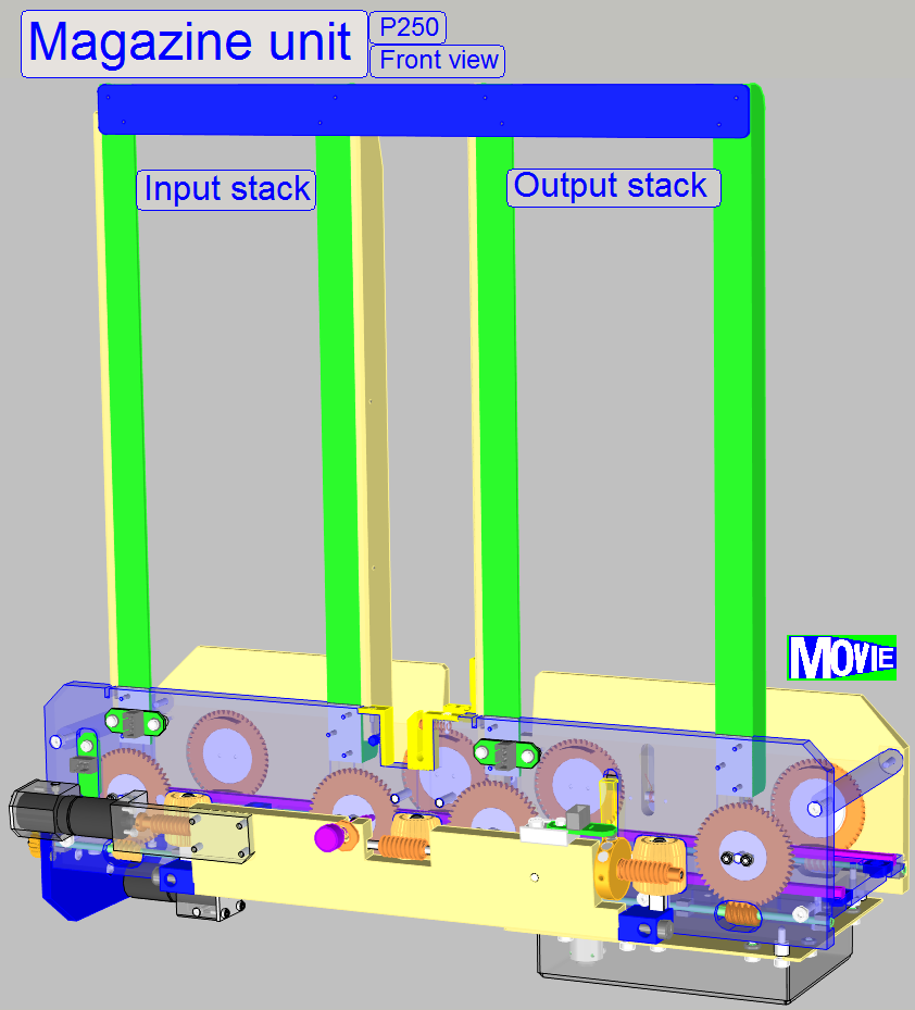
 The magazine unit is a component, added to the Pannoramic P250 scanner,
to give the possibility of loading and unloading of magazines and insertion and
removal of slides, automatically. To handle the slides, magazines are used with
25 slide positions.
The magazine unit is a component, added to the Pannoramic P250 scanner,
to give the possibility of loading and unloading of magazines and insertion and
removal of slides, automatically. To handle the slides, magazines are used with
25 slide positions.
The magazine input and output
stack respectively can hold up to 9 magazines; after the first magazine is
loaded into the magazine feeder channel, the 10th magazine can be
placed into the input stack.
The presence of a magazine in
the input stack is sensed by the magazine input stack sensor.
The magazines are placed
manually into the input stack and are manually removed from the output stack by
the user.
If the scan process of the
slides in the 10th magazine is finished, and the output stack
contains 9 magazines, the output stack sensor signals the state “Output stack
full”. In this case, at least one magazine has to be removed from the output
stack, only then the 10th magazine can be moved from the magazine
feeder channel into the output stack.
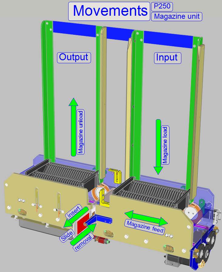
The magazine load
procedure moves the magazine with the help of the magazine load mechanism from
the input stack into the magazine feeder channel or, if a magazine is present
in the magazine feeder channel, the magazine is moved into the output stack at
the same time.
The magazine feeder moves the
magazine in the magazine feeder channel to the left or to the right as required
and has 2 tasks:
· It moves the
magazine from the magazine load position to the first slide position and from
the last slide position to the magazine unload position.
· It moves the
magazine from the actual slide position to the next or previous slide position
if a slide exchange is done or to any desired slide position of the magazine.
 The slide loader inserts the slide
from the actual slide position of the magazine into the Specimen holder (slide
holder) of the XY-Stage and, after the scan procedure is finished, it removes
the slide from the specimen holder back into the magazine.
The slide loader inserts the slide
from the actual slide position of the magazine into the Specimen holder (slide
holder) of the XY-Stage and, after the scan procedure is finished, it removes
the slide from the specimen holder back into the magazine.
If the automatic scan mode is selected all slides in the magazine are
inserted sequentially from the magazine into the specimen holder, scanned by
the scanner unit and removed from the specimen holder back, into the magazine
automatically after the scan process of the actual slide is finished. If all
slides of the actual magazine are scanned, the magazine is unloaded from the magazine
feeder channel into the output stack
meanwhile the next magazine will be loaded from the input stack, if there is
any further magazine.
If the manual scan mode is selected
the Magazine load and unload, the slide insert and removal procedures are
controlled via software
buttons. The mechanical movements are the same as described for the
automatic scan mode.
Enhancements on the magazine unit of the P250 in relation to the SCAN
150
- The stack rails are prolonged; so the input
and output stack may contain up to 9 magazines.
- The construction of the stack rail spacer
is modified.
- In the stack rail of the input stack a
sensor is implemented and shows the state “magazine
present”.
- The sensor in the output stack signals the
state “output
stack full”.
- Because two new sensors are implemented,
additional sensor
connections are realized and connected to the DC controller.
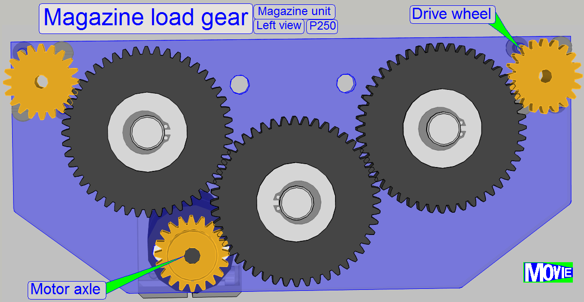
- The
magazine load gear got an additional drive cog wheel on the motor
axle; so the speed for lowering down the magazine is reduced.
- The
magazine feeder motor with gear is of a different type; so the feeder
moves the magazine more slowly.
- The acting edge of the magazine
feeder sensor was modified. Now the
rising edge is used, so the magnets of the magnet
disc will not stop on the sensor, the stop position is always after
the magnet has passed the sensor.
- The
magazine load procedure control and the procedure to detect the
presence of a magazine in the feeder channel are modified.
- On the output stack part of the magazine
channel side walls magazine
supporters are realized. These supporters prevent the magazine(s) from
falling down if a magazine load action is initiated and no magazine is
present in the magazine channel to be moved into the output stack.
- On the bottom plate of the magazine channel
the “specimen
holder fixing fork” is realized; it fixes the position of the specimen
holder during the slide insert or removal action. Because the focus pin is
not in connection with the specimen holder during slide loading, the
Z-position of the specimen holder is fixed in this way.
- On the left side of the magazine feeder
channel bottom plate a magazine
movement limiter is realized to prevent the brightfield scan camera if
wrong magazine movement is executed (might be done with the service program).
- The slide loader “Outer
finger” and “Inner finger” are modified in shape.
- The slide leader of the slide loader is not
used (dismounted); a slide
leading spring is used instead.
The exchange of
the entire magazine unit is necessary:
- If one of the two
magazine handling DC motors or the DC controller electronics is faulty.
- If the shape of any
part is deformed or a part is broken.
- If the magazine unit
has any fault and you are unable to
fix it.
Requirements
- Service program for Pannoramic
scanners (SlideScannerService.exe)
with actual license file
- Pannoramic
SCAN and Pannoramic Viewer software (SlideScanner.exe,
SlideViewer.exe)
with dongle or actual license file
- 1.5, 2.5, 3
and
- Hardware and construction knowledge of the
Pannoramic 250
 Attention: Do
not mix the versions of SlideScanner.exe and SlideScannerService.exe! Always
use these programs with the same version number; otherwise the
SlideScannerService.exe program could produce unwanted results and
SlideScanner.exe does not work correctly or even freeze!
Attention: Do
not mix the versions of SlideScanner.exe and SlideScannerService.exe! Always
use these programs with the same version number; otherwise the
SlideScannerService.exe program could produce unwanted results and
SlideScanner.exe does not work correctly or even freeze!
Since the
software version 1.15 the units of the scanner are configured in the file
“MicroscopeConfiguration.ini”, section [Microscope].
The actual version of the magazine unit and slide loader in the scanner
Pannoramic 250 is “LoaderType=SL_9Mag_25Slide_Sensor_Vertical”.
[Microscope]
SerialNumber=xxxxx
MicroscopeType=3DMic9
ScanCameraType=
PreviewCameraType=CVrmc_m8_pPro
BarcodeReaderType=PreviewCamera
LoaderType=SL_9Mag_25Slide_Sensor_Vertical
CameraChangerType=CC_3DH_2Pos
ReflectorTurretType=RT_3DH_10Pos_Belt
BrightfieldLightSourceType=FlashLight2010
ObjectiveChangerType=OC_2Pos
ObjectGuideXYZType=OGXYZ_FLASH3
FlashUnitType=FlashUnit_Type2
NDFilterType=NDType2
PreviewLightType=PreviewLightUnitType_Type2
PowerSwitchBoardType=PowerSwitchBoard_Type1
If a different
value is used for the magazine unit, may be units are not recognized or working
wrong!
![]() Parameter options of
the section
Parameter options of
the section
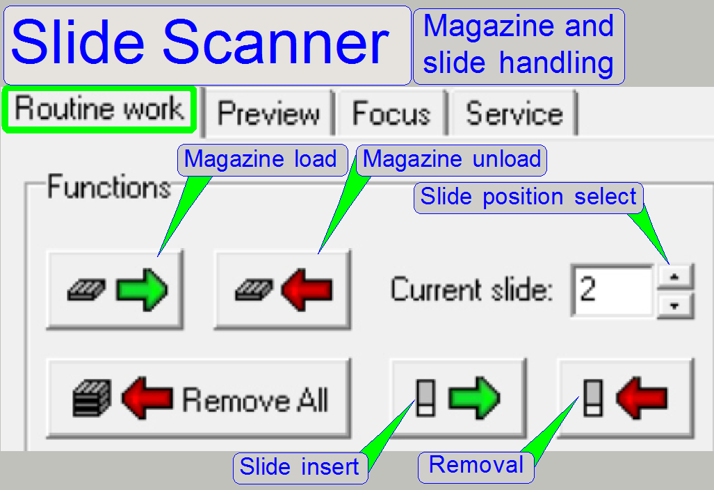
- In the program “SlideScanner.exe”
the movement of the magazine is controlled via the magazine load and
unload buttons in the tab “Routine work” if the manual scan operation is
selected.
- The slide loader inserts and removes the slide during the slide
insert or removal operation.
·
To select a specific slide position of the
magazine, the “Current slide” position may be incremented or decremented by the
use of the buttons of the numerical field, or you may type a value between 1
and 25 into the numerical field.
·
By pressing the button “Slide insert” the
magazine is moved to the desired slide position (shown in the numerical field)
and then, the slide will be inserted. Is a slide in the specimen holder and the
button “Slide insert” is pressed with a modified slide position, the slide will
be removed first, before the magazine is moved.
Load a magazine
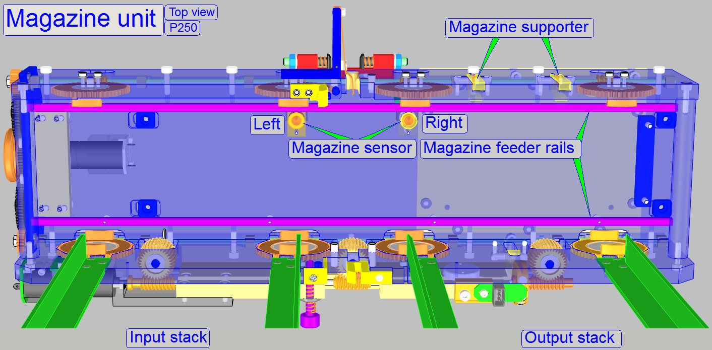
The “Magazine
load motor” is started with the software button “Load magazine”. By rotating the “Magazine
input stack wheels” the first magazine is placed onto the “Magazine feeder
rails” of the
magazine channel. The end of the process is signaled by the “Magazine load
sensor” and the “Magazine load motor” is switched off by software.
Watch video: Magazine load_P250
Magazine unload_P250
Unload a magazine
If the scan session of the actual magazine is finished
or the
magazine remove command is issued, the magazine is fed to the output stack
position. The exact magazine unload position is defined by the “Right
magazine sensor” actuation. If the magazine releases the sensor, the
forward movement of the magazine is stopped and a backward movement is
initiated. If the sensor is pressed again (after 1 revolution backward) the
correct magazine unload position (and the magazine load position also) is
reached and a magazine unload procedure starts. Meanwhile the magazine will be
unloaded into the output stack; the next magazine (if any exists) is loaded
from the input stack to the feeder channel.
Feed
a magazine
If a magazine arrived onto
the magazine feeder rails the “Left Magazine Sensor” will be pressed. Even the
weight of an empty magazine is able to push this sensor. This sensor signals
the software, that a magazine had been loaded and a magazine is present in the
magazine feeder channel. The magazine feeder motor is switched on by software
and transports the magazine with the help of the feeder gear to the first slide
position. During magazine feeding the “Magazine feeder sensor” (not shown)
gives a pulse after each full turn of the feeder spindle to the software via
the DC electronics and the USB electronics box. The software counts the pulses
of the “Magazine feeder sensor” and finds the magazine position for the actual
slide to be inserted. The distance between two slide positions is exactly 2
full turns of the feeder spindle.
Insert
a slide
The slide loader inserts the slide
to be scanned from the actual magazine’s slide position into the specimen
holder (slide holder) of the X-Y-Stage by pressing the “slide load button”
and removes the slide from the specimen holder and returns it to the slide
position of the magazine, if a slide removal procedure is initiated by the
“Slide remove” button.
Watch video: Slide insert
Control and interface unit
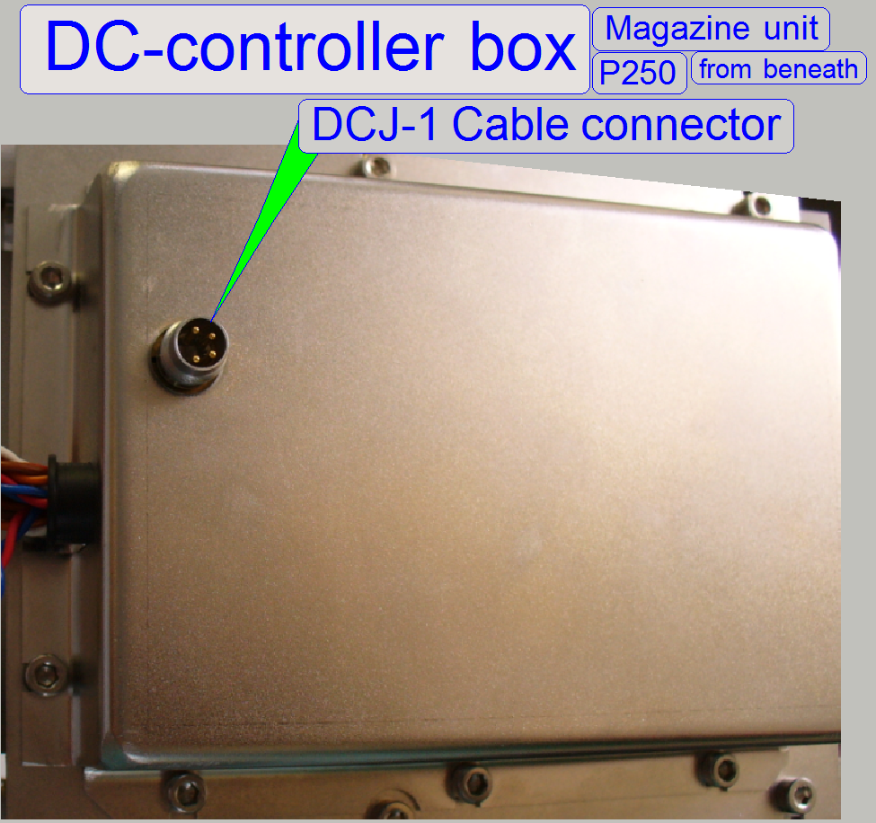 The DC control electronics box is found
on the magazine unit from beneath. The commands to switch on or off the motors
(or any connected device) are issued from the software (SlideScanner.exe
or SlideScannerService.exe)
via the USB
Controller and the cable DCJ-1. The status information (the state of the
sensors) is read by the software on the same way. To prevent the motors from
overload if hardware jamming occurs, all commands, issued by the software
“SlideScanner.exe”, starting the DC motors with a time out also. Normally, the
motor is stopped with the sensor action before the time is run out. If the
sensor action is missed (jamming occurred) the time out event will switch off
the motor and so protecting them from overload.
The DC control electronics box is found
on the magazine unit from beneath. The commands to switch on or off the motors
(or any connected device) are issued from the software (SlideScanner.exe
or SlideScannerService.exe)
via the USB
Controller and the cable DCJ-1. The status information (the state of the
sensors) is read by the software on the same way. To prevent the motors from
overload if hardware jamming occurs, all commands, issued by the software
“SlideScanner.exe”, starting the DC motors with a time out also. Normally, the
motor is stopped with the sensor action before the time is run out. If the
sensor action is missed (jamming occurred) the time out event will switch off
the motor and so protecting them from overload.
Mounting
The DC control electronics box is mounted to the inner
and outer side wall of the magazine feeder channel with 4 bolts from beneath.
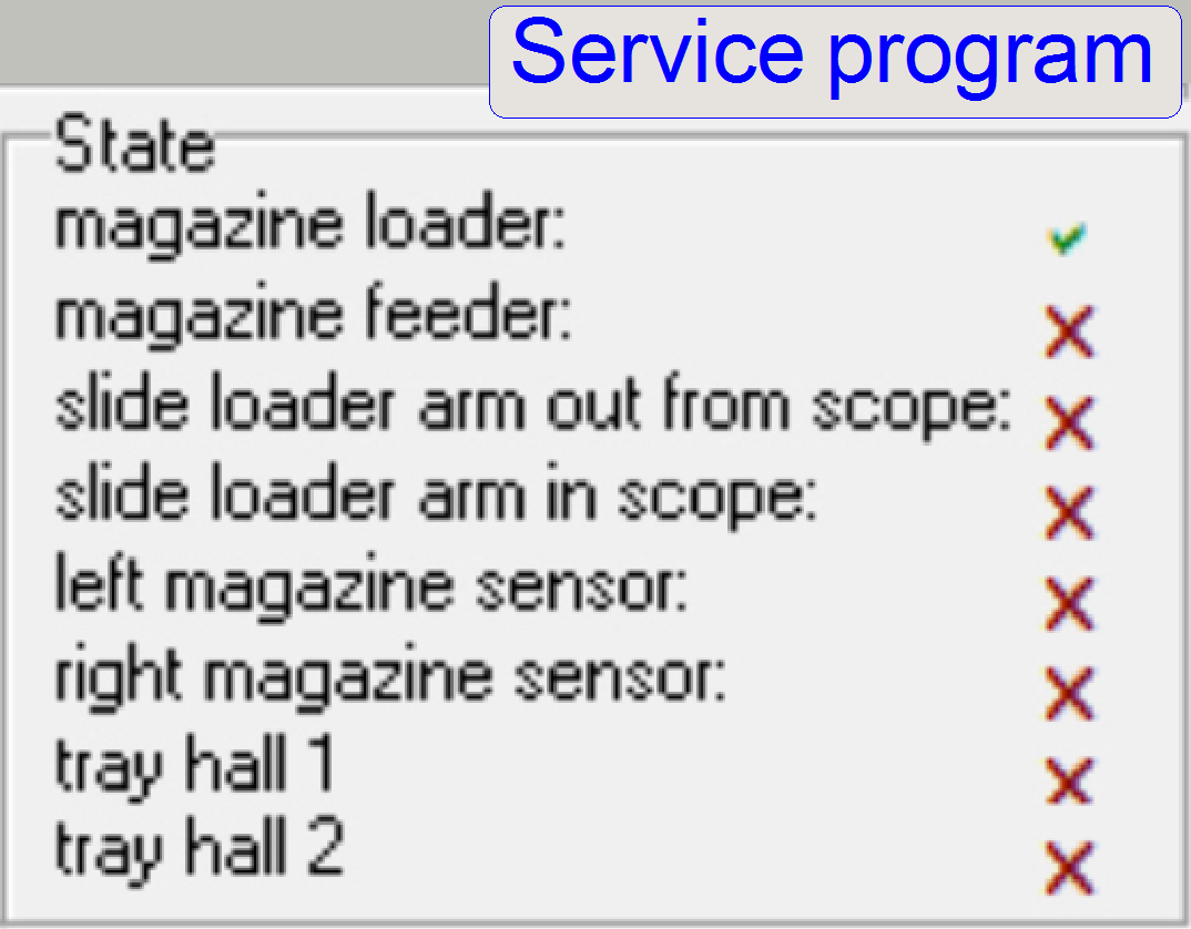
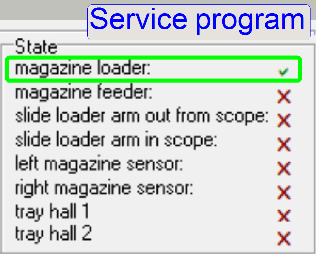
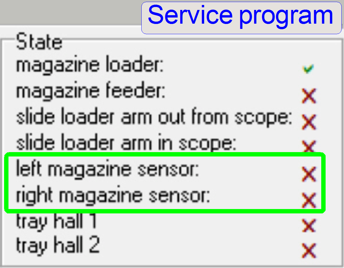
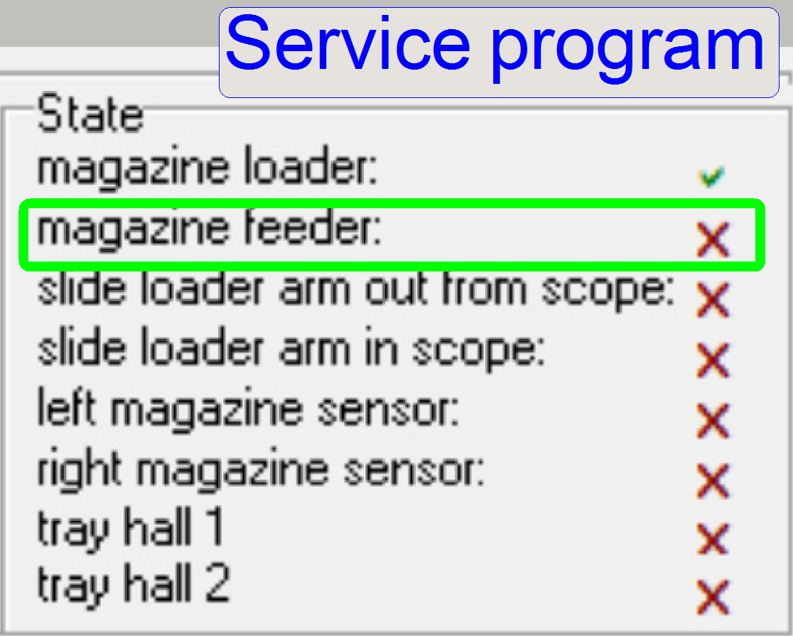
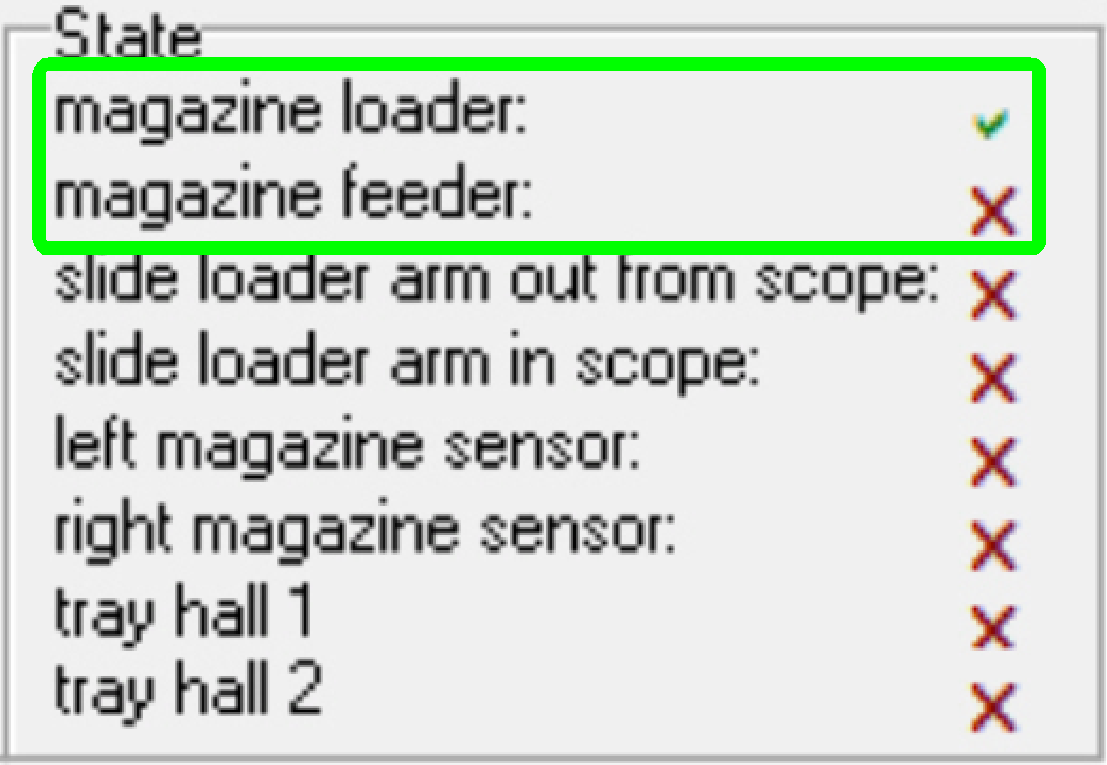
The state of the
connected sensors is shown in the service
program “SlideScannerService.exe’.
- Switch “Active” the section “DC controller”; and the field “State”
shows the actual sensor state.
![]() = acting position found; sensor
attached
= acting position found; sensor
attached
X =
unattached or unknown
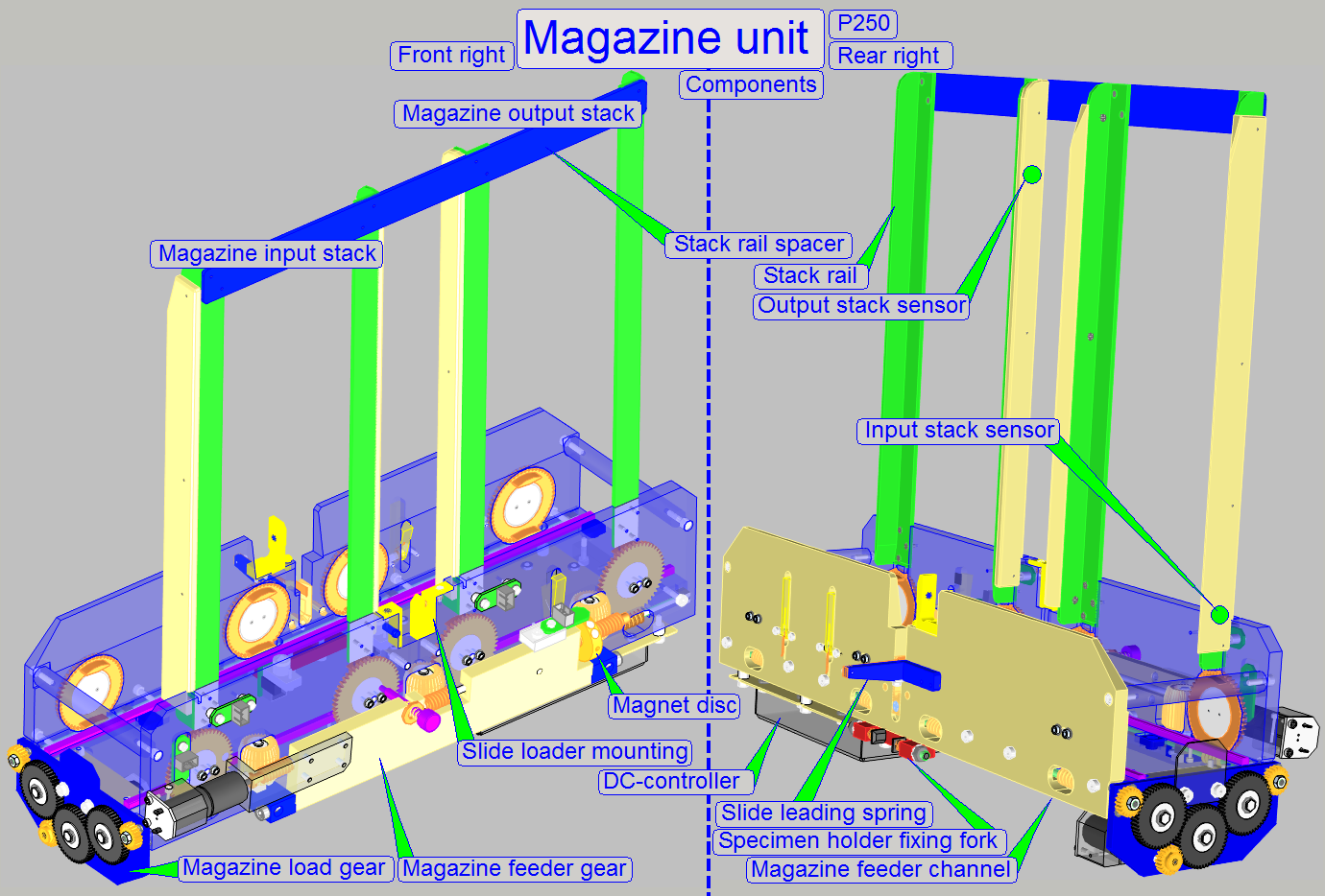
Components and construction
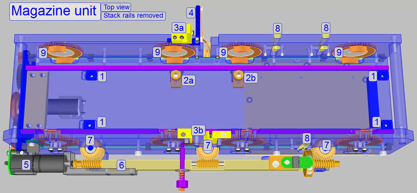
2a Magazine
input (left) sensor
2b Magazine
output (right) sensor
3a, 3b Slide
loader mounting
4 Slide leading
spring with holder
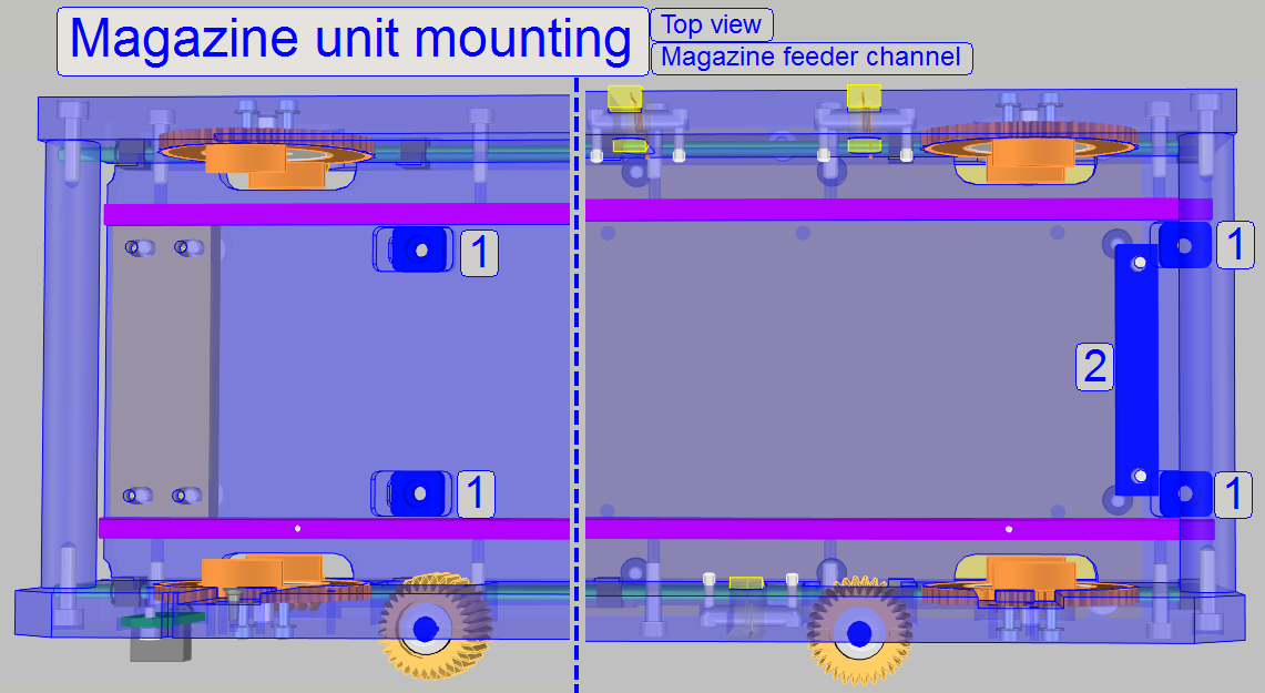
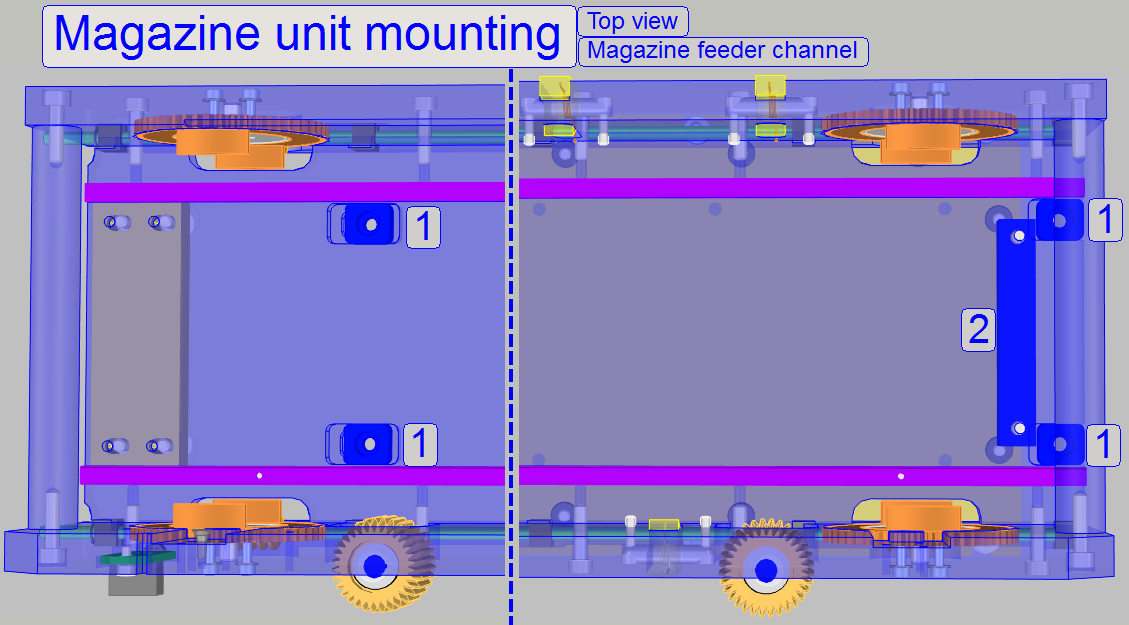
The entire magazine unit is mounted to the truss by the use of 4 washers
and bolts (1).
· If the magazine
unit should be dismounted, please remove the bolts.
· If the position of
the magazine unit should be adjusted, please loosen the bolts barely.
![]() “Truss”; “Magazine
unit position adjustment’; “Adjust
the position of the magazine unit”; “Remove”
and “Mount
the magazine unit”.
“Truss”; “Magazine
unit position adjustment’; “Adjust
the position of the magazine unit”; “Remove”
and “Mount
the magazine unit”.
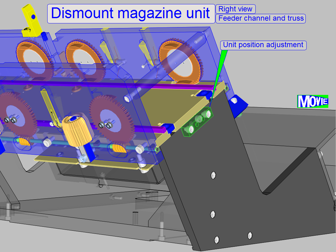
1.
Remove the
preview illumination cable BGJ-1.
2.
Remove the cable HMJ-1 from the slide loader and
remove the entire slide loader also.
3.
Remove the cable DCJ-1 from the DC controller unit.
4.
To remove the "Unit position adjustment
cover", remove and loosen respectively the bolts as shown; the cover can
be moved downward. Loosen the adjustment
fixing bolt a little bit.
5.
Remove the mounting bolts for the Magazine unit (1)
see above.
6.
Move the entire magazine unit upward.
Mount magazine unit
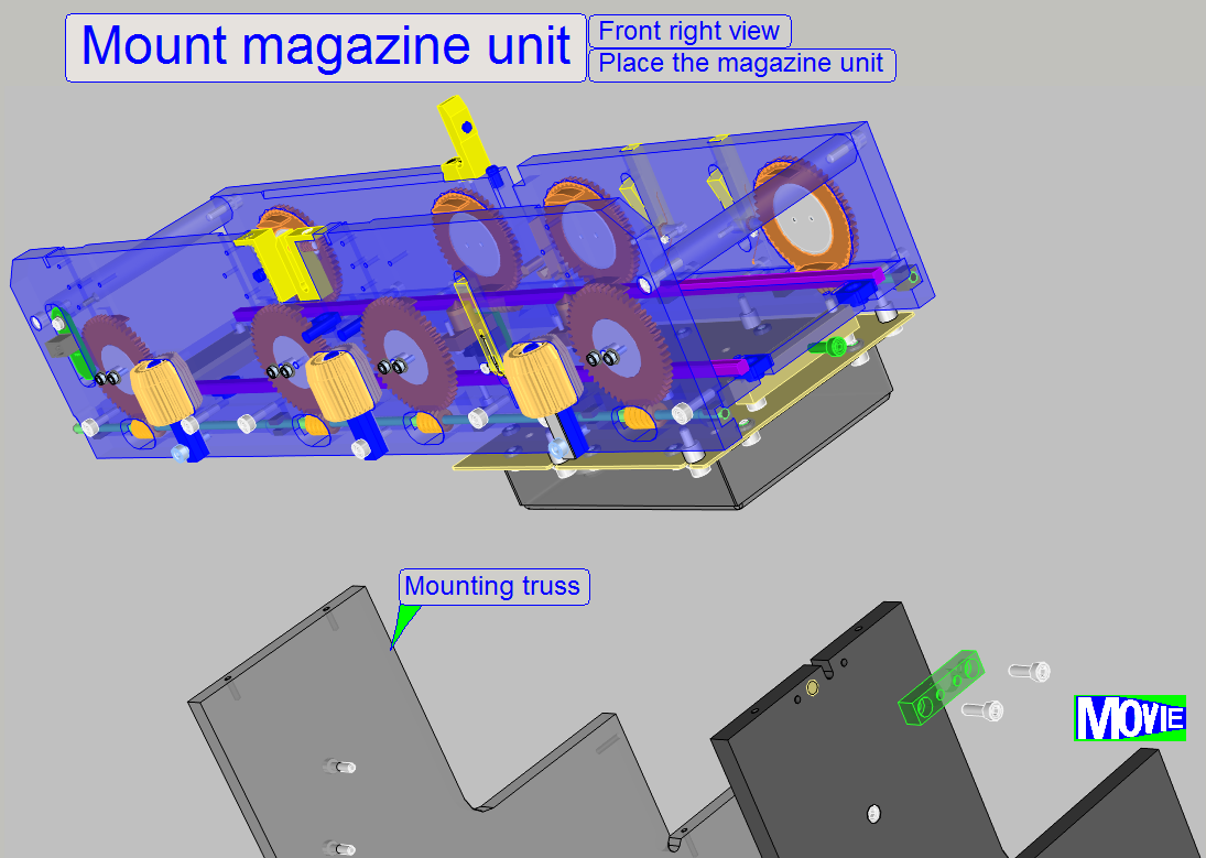
1.
Place the
magazine unit onto the truss.
2.
Insert the mounting bolts with the washers and tighten
these carefully.
3.
Connect the cable DCJ-1 for the DC controller unit.
4.
Connect the preview illumination cable BGJ-1.
5.
Insert the slide loader and connect the cable HMJ-1.
6.
Adjust the magazine loader as described in “Adjust
the magazine load mechanics”.
7.
Adjust or check the magazine unit position as
described in “Define
the slide insert and removal positions”.
8.
Mount the cover of the magazine unit position
adjustment.
9.
Execute the magazine load and unload procedures with
the service program.
10. Execute the slide
loading test of the service program with different slide sizes, slide shapes
and different magazines also.
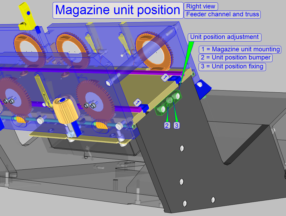
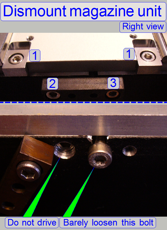
It may happen that the magazine unit needs to be
removed for some adjustments. if the position of the magazine unit is already
adjusted, and the unit needs to be removed, the adjusted position would be
lost.
With the adjustable bumper (2) the magazine unit
position is defined.
If the magazine unit is placed onto its mounting,
easily push the entire unit against the bumper, tighten the unit position
fixing (3) barely and tighten the Magazine unit mounting bolts (1) from the
top.
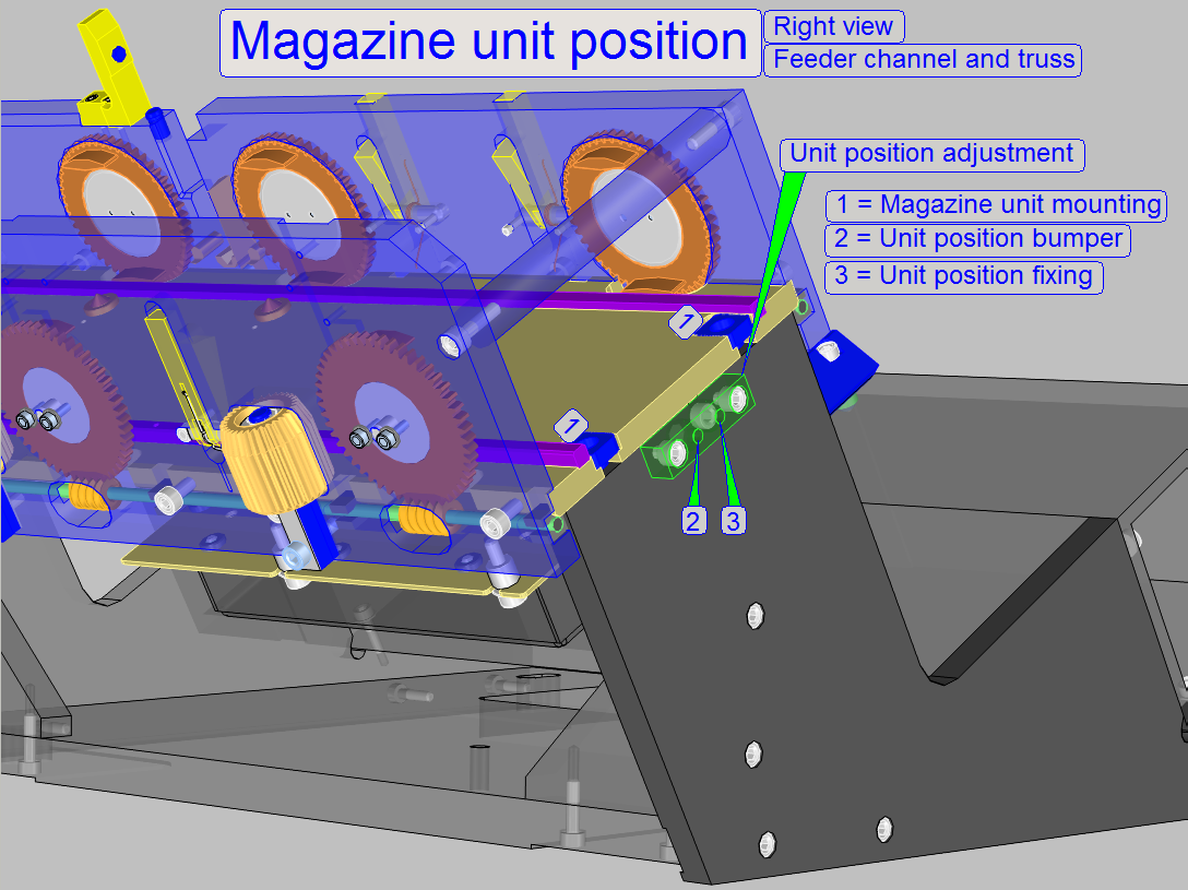
If the magazine unit position should be adjusted, the
magazine unit mounting bolts (1) must be loosened a little bit to make the
magazine unit barely moveable. With the bumper position (2) adjustment and the
position fixing (3) bolt the entire magazine unit can be moved to the left or
to the right to find the correct position for the slide position guide and the
inner finger of the slide loader in relation to the specimen holder.
The position fixing bolt should be loosened if the position adjustment
bolt is turned clockwise; the entire magazine unit moves to the left.
Important
If the unit position bumper is turned counter clockwise, please pull the
entire Magazine unit manually to the right, until the bumper is reached again!
Adjust the magazine unit
position
If the position adjustment bolt is turned counter clockwise (loosened),
the entire magazine unit can be moved to the right by carefully tightening the
position fixing bolt.
If the adjustment is finished, the position adjustment bolt should touch
the magazine unit and the position fixing bolt should be even tighten. With
this solution the adjusted position is not lost and the correct position of the
magazine unit is found again, even if the entire magazine unit was removed.
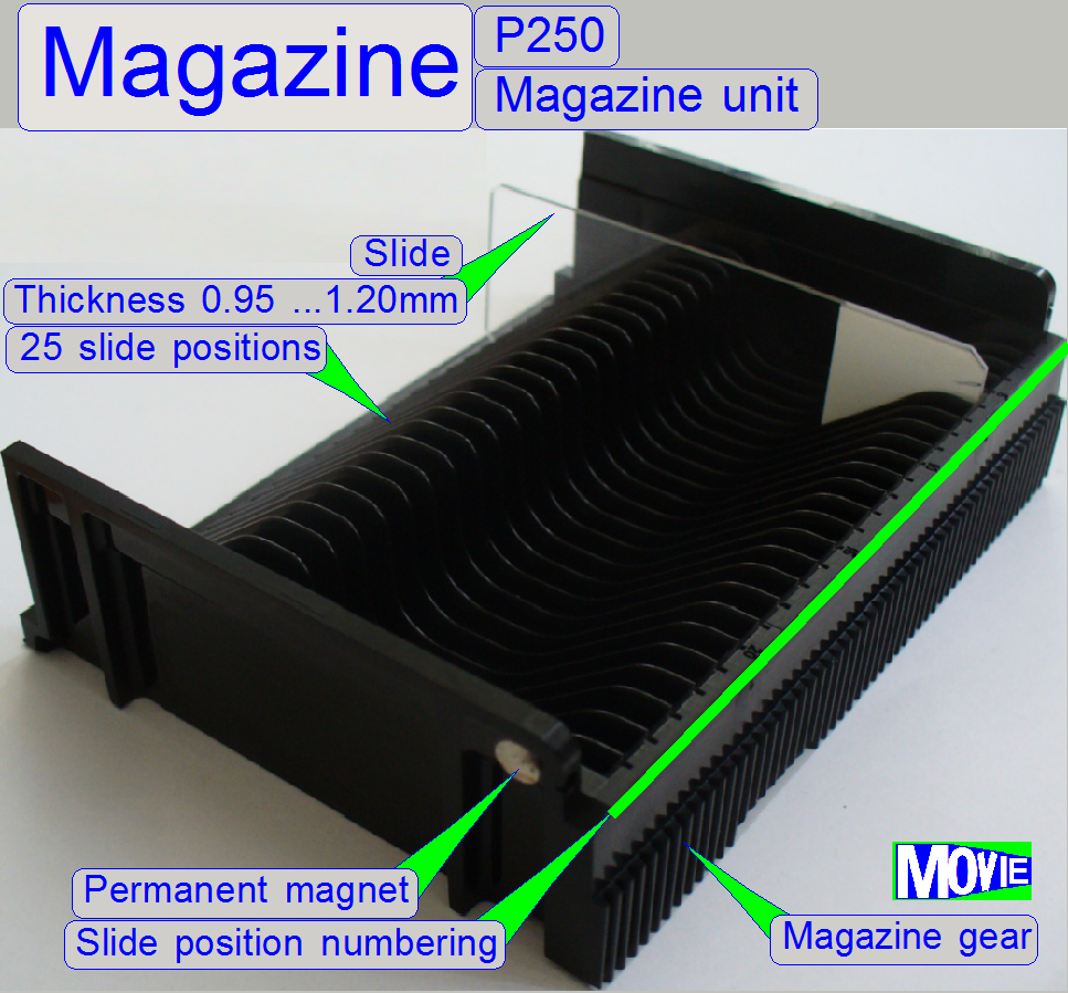
The magazine has 25
positions and can so contain up to 25 slides with a thickness of up to 1.4mm,
meaning the thickness of the cover slip and the barcode label is included.
Insert the slide into the magazine so, that the cover slip shows always to the
objective during slide insertion and scanning. The slide position numbering is
realized on the upper edge of the rear wall.
The magazine is moved with the
feeder gears and the rack on the rear of the magazine.
A metal plate (to increase the slide removal security)
is integrated.
- The slide positions of the magazine should be kept clean and dry;
dust, paraffin residues or small glass shards may cause slide loading
difficulties!!
- The magazine does not need adjustment.
Permanent
magnet
The permanent magnet of the magazine is used to signal
to the appropriate sensor the states “magazine present in the input stack” and
“Output stack full”; see also “Magazine input
stack sensor” and “Magazine
output stack sensor”.
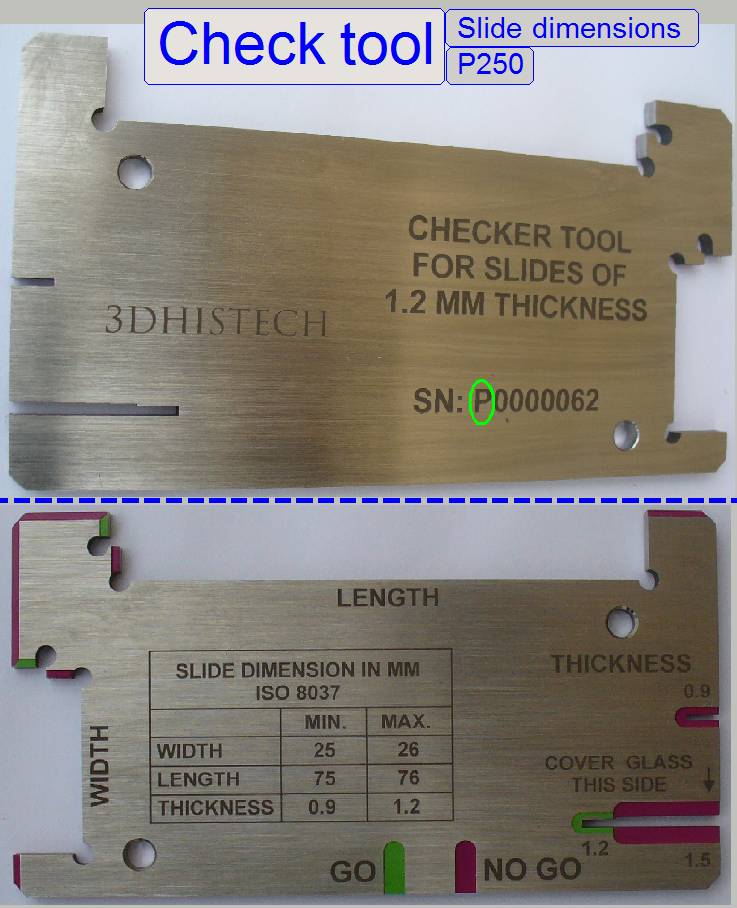
Length: 75.00 to 76.00mm
Width: 25.00 to 26.00mm
Thickness: 00.95 to 01.20mm
Since January
- If the first
character of the serial number is an “S” the tool is used to
check the slide dimensions of the scanners “SCAN, “
- If the first
character of the serial number is a “P” the tool is used to
check the slide dimensions of the scanner “P250”.
·
Please check the slide dimensions before filling the
magazine!
The cover slip should be in distance
from the lower slide edge, in distance from the slide holding mechanics of the
specimen holder; not less than 1.0mm from the slide edge.
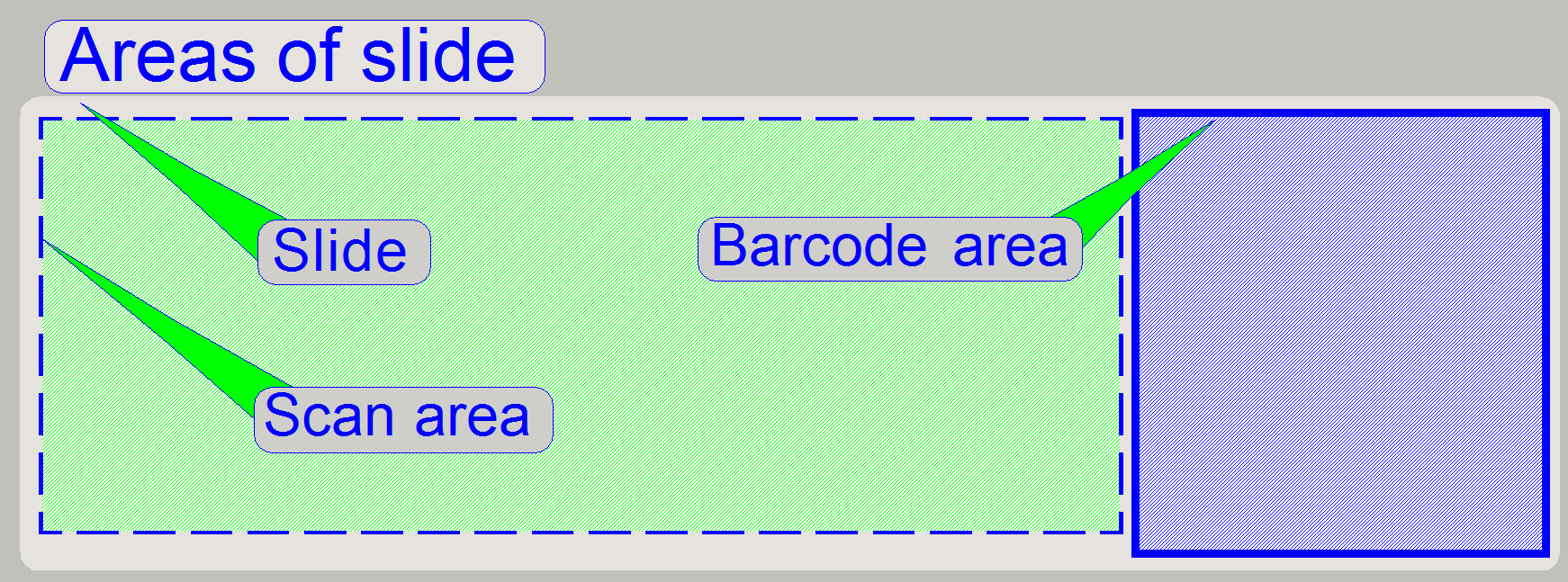
Because the slide holds the tissue to be scanned, the
slides have to fulfill optical requirements also.
The slide bottom (the
surface, oriented to the
condenser) must be clean and dry.
- Dust and paraffin residues may result in focusing difficulties
(because the
focus pin contacts this surface) or may generate vibration during the
slide scan process, resulting in reduced quality of the virtual tissue.
- The slide is mechanically fixed by the slide clamp on
the barcode area. Therefore, never use stickers or labels on the bottom of
the barcode area, because these produce a deviation of the field of view in
relation to the optical axis; the result will be a “Slanted FOV”; see
also: “The
stage skew check”.
The top of the
slide (the surface, oriented to the objective) holds the
tissue together with the cover slip.
- Keep the top of the cover slip clean and dry. Dust or paraffin
residues may cause focusing difficulties during the slide scan process,
resulting in reduced quality of the virtual tissue.
 Before inserting the slide
into the magazine, wait, until the cover slip glue is already dry,
otherwise, residues may occur on the slide slot bottom of the magazine and
then slide loading difficulties are the result.
Before inserting the slide
into the magazine, wait, until the cover slip glue is already dry,
otherwise, residues may occur on the slide slot bottom of the magazine and
then slide loading difficulties are the result.
![]() “Specimen holder”; “Cleaning optics”
“Specimen holder”; “Cleaning optics”
 The stack contains the magazines for slide scanning in the input stack
and holds the finished magazines in the output stack. In the input stack as
well as in the output stack maximal 9 magazines can be placed.
The stack contains the magazines for slide scanning in the input stack
and holds the finished magazines in the output stack. In the input stack as
well as in the output stack maximal 9 magazines can be placed.
- If the 1st magazine is load
from the input stack into the magazine feeder channel, the 10th
magazine can be inserted into the input stack.
- If the 9th magazine is removed
from the output stack, the 10th magazine can be moved from the
magazine feeder channel to the output stack.
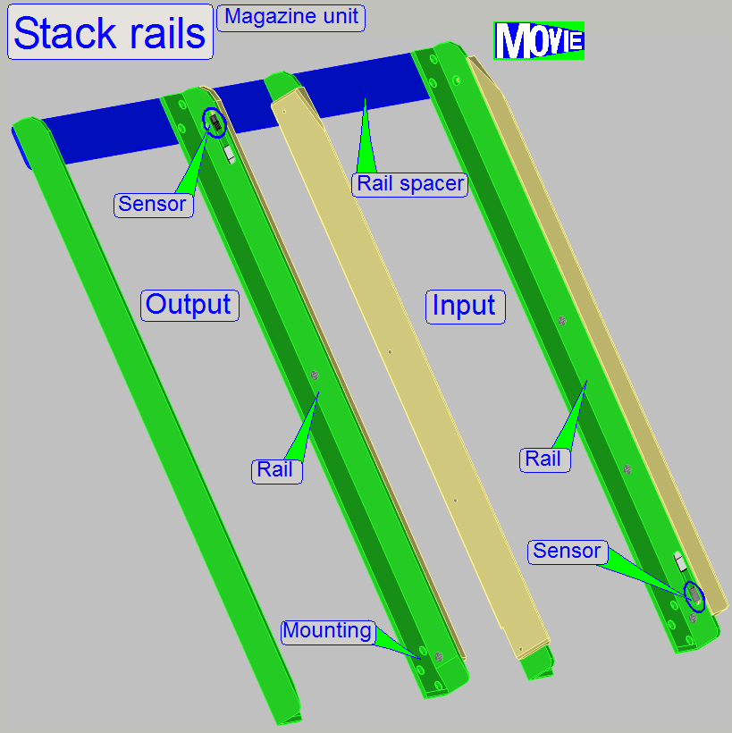
Stack rails
The stack rails are rotated
by 30 degrees against the plump vertical and so the slides are placed always on
the rear of the magazine by gravity. This solution ensures also a smooth
downward or upward movement of the magazine during the load and unload
procedure.
Stack rail spacer
It defines the upper
distance of the stack rails to each other and guarantees the parallelism of the
stack rails.
The magazine input stack
sensor signals the presence of a magazine in the input stack, so the magazine
load procedure can be started by the software.
If 9 magazines are situated
in the output stack, the output stack sensor signals the state “output stack
full”.
The 10th magazine
can be removed from the magazine channel to the output stack only, if at least
1 magazine is removed from the output stack.
![]() ‘Input and output
stack sensors”
‘Input and output
stack sensors”
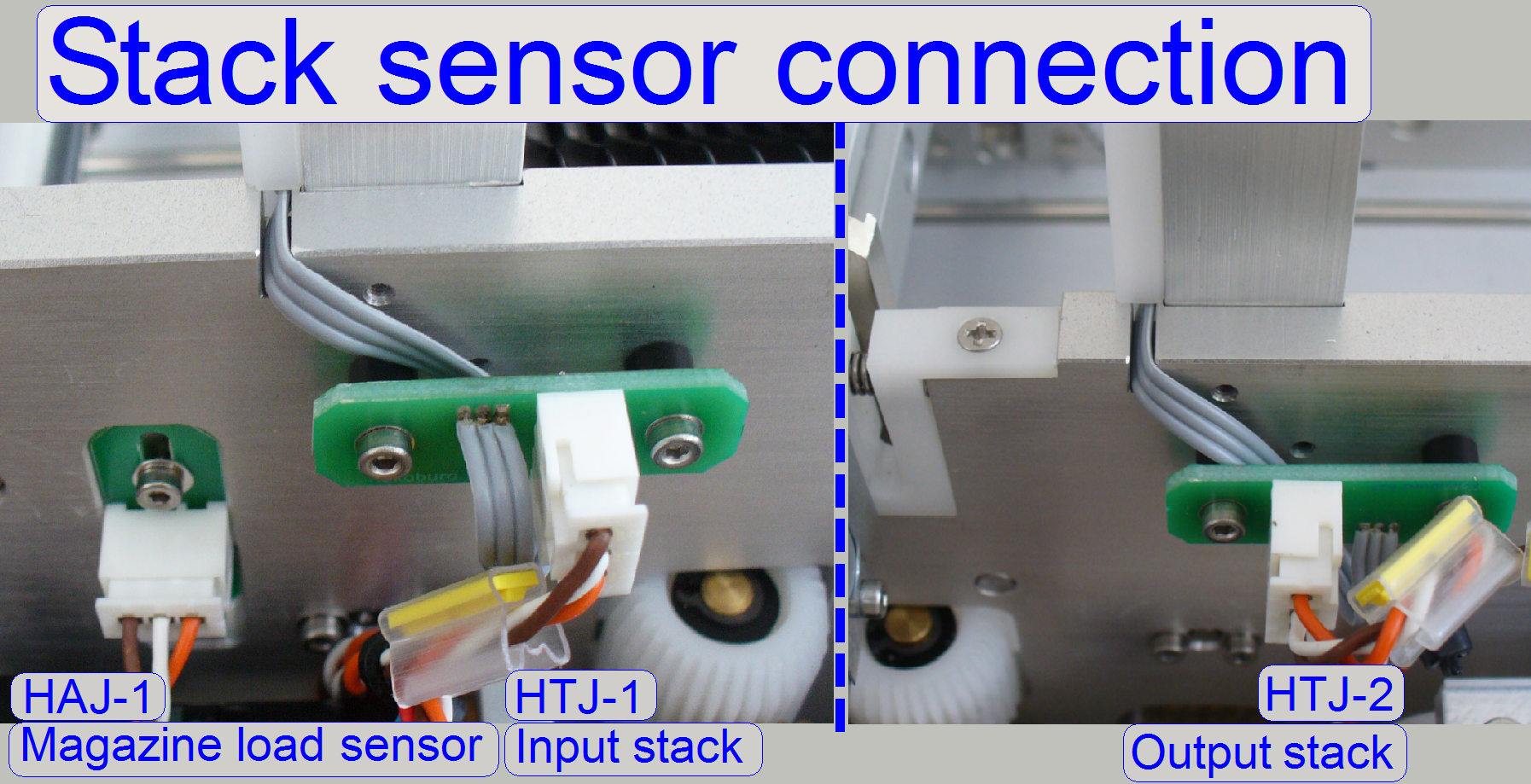 The input and
output stack sensors are realized with Hall elements; their positions are
fixed, so they can not be adjusted.
The input and
output stack sensors are realized with Hall elements; their positions are
fixed, so they can not be adjusted.- The sensors are connected to the
DC-controller via the cables “HTJ-
- The action of the sensor is initiated by
the permanent magnet, placed into the side wall of the magazine.
In the service
program
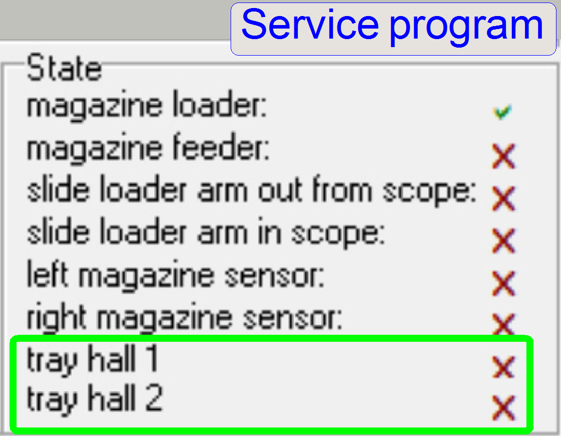 The input stack sensor “HTJ-1” is shown as “tray
hall1” and
The input stack sensor “HTJ-1” is shown as “tray
hall1” and - The output stack sensor “HTJ-2” is shown as “tray
hall2”.
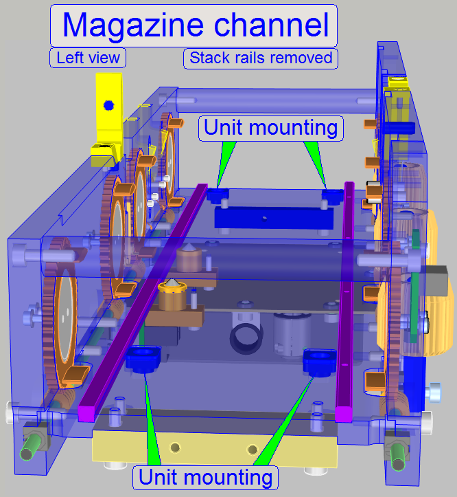
The magazine feeder channel together with the feeder rails ensures
proper movements of the magazine in horizontal direction, to the desired slide
position or to the magazine unload position. If the magazine was just loaded,
the magazine will be moved automatically (controlled by software) to the first
slide position of the magazine.
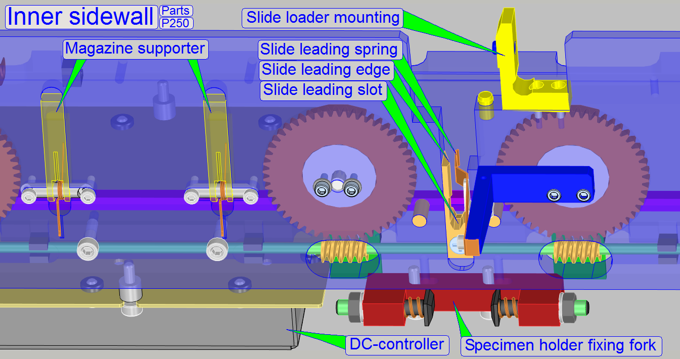
The magazine feeder channel consists of the
following main parts
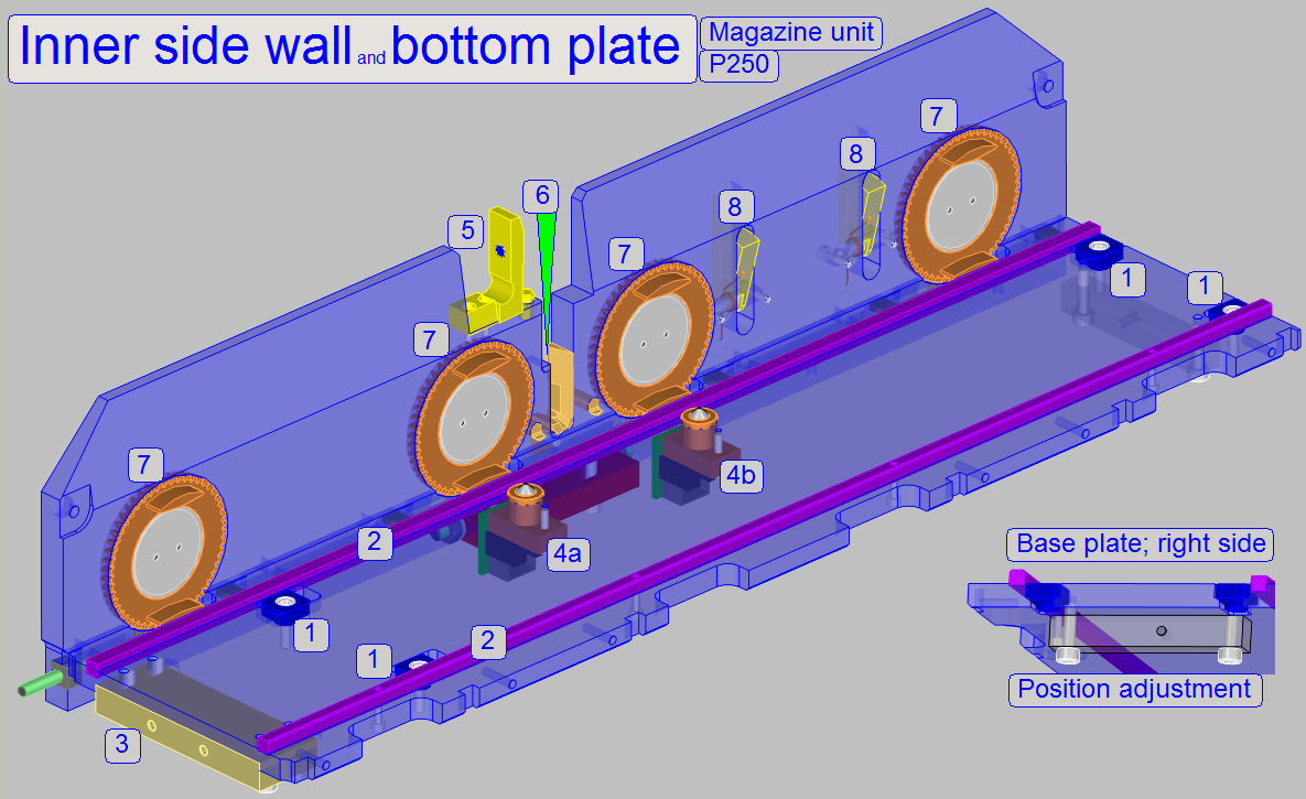
Inner
side wall with
- Input
and output stack wheels (7) with worm spindle and mountings.
- Inner slide
loader mounting (5).
- 2 Magazine
supporters (8) on the output stack’s side.
- Slide leading
slot and slide leading edge (6); used during the slide insert
procedure.
- Slide
leading spring with spring holder (not shown); used during the slide
insert procedure.
- Specimen
holder fixing fork (not shown here); used during the slide insert and
removal procedures.
Bottom
plate with
- Magazine
unit mounting to the truss (1).
- Magazine
feeder rails (2).
- Left magazine
(input) sensor (4a)and the right magazine
(output) sensor (4b).
- Magazine
unit position adjustment (on the right side).
- Magazine
load gear (9) and mounting (3).
- Magazine
movement limiter on the left side (9a).
- DC controller
(from beneath).
- The entire magazine feeder channel should be kept clean and dry.
- Dust and glass shards can be removed easily with a brush from the
magazine bottom plate and other parts.
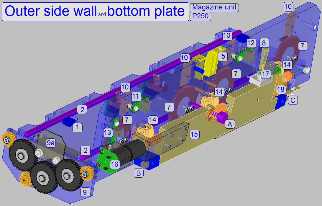
Outer
side wall with
- Input
and output stack wheels (7) with worm spindle and mountings.
- Outer slide
loader mounting (5).
- Mountings for the
stack rails (10).
- 1 Magazine
supporter (8) on the output stack’s side.
- Connectors
for the input and output stack sensors (11, 12).
- Magazine
load sensor (13) with mounting.
- Magazine
feeder gears (14).
- Mountings for the
magazine feeder unit (A, B, C).
- Magazine feeder drive mounting plate (15).
- Feeder motor (16)
- Feeder sensor (17)
- Feeder disc (18)
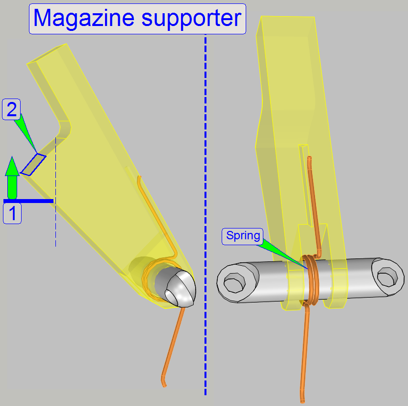
On the inner and on the outer side wall of the
magazine channel output stack part magazine supporters are realized.
The supporters are required, if magazines are present
in the output stack and no magazine is in the magazine feeder channel during a
magazine load procedure is in progress.
If the supporter would be missed (or it works wrong)
the magazine would falling down onto the output stack wheels and magazine
jamming might occur.
Solution
If the magazine
moves upward from the feeder channel in direction to the output stack, the
supporters are pushed outward by the front and the rear part of the magazine
(1).
The diameter of
the magazine output stack wheels is some 10th mm more than the
height of the support surface (2); so, if the vertical position of the magazine
output stack wheels is reached, the spring pushes the support surface (2) under
the magazine.
If now a magazine
unload procedure is in progress without a magazine in the feeder channel, the
magazine(s) moving downward only some 10th mm and then the magazine
movement is stopped by the support surface (2).
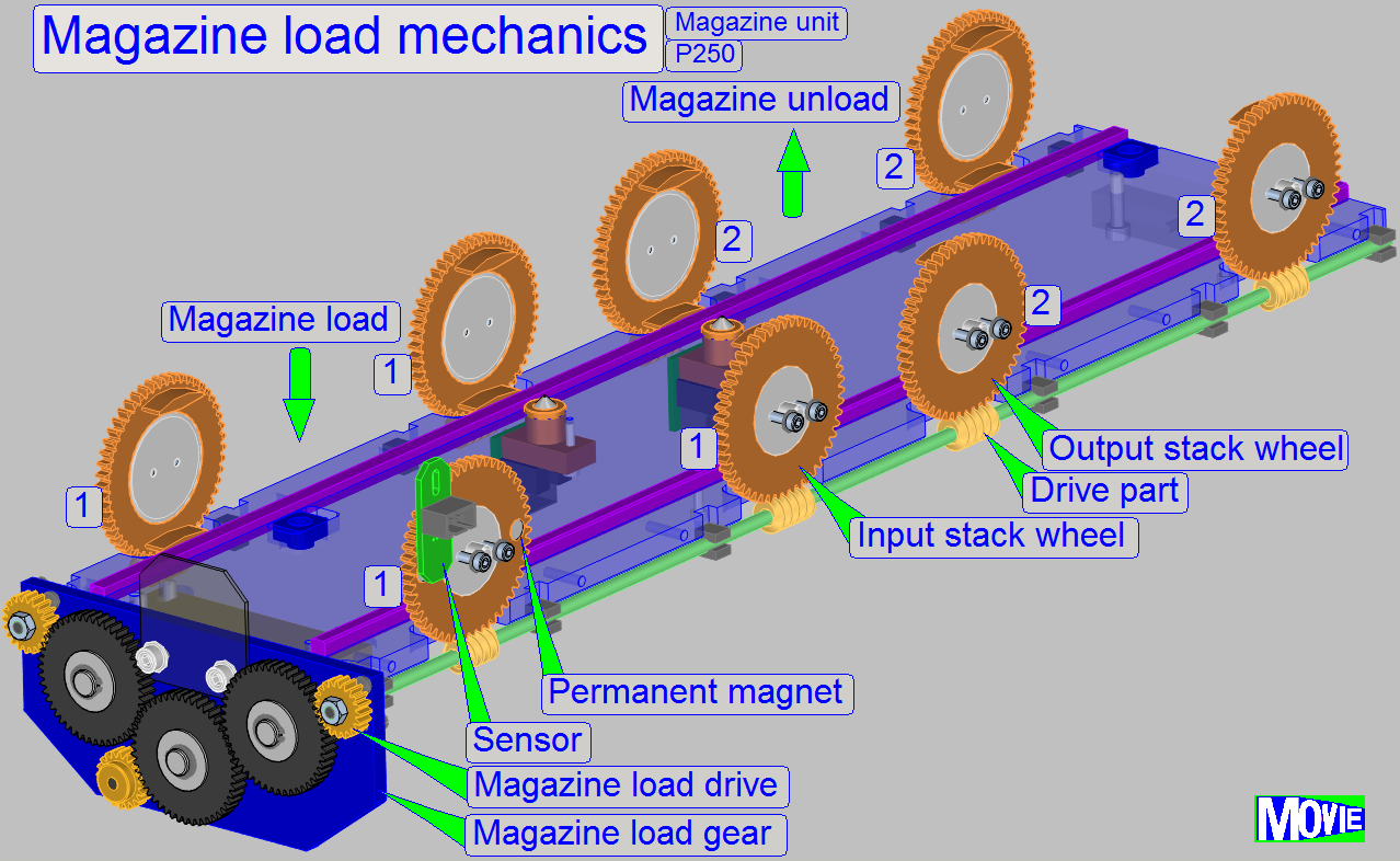 The magazine
loader unit consists of
The magazine
loader unit consists of
·
Input and output stack wheels
The magazine load
and unload drive part of the magazine unit moves the magazines in vertical
direction, from the magazine input stack onto the magazine feeder rails by the
help of the input stack wheels (1) and from the magazine feeder rails to the
output stack respectively. Both actions are realized with the same motor and
mechanical drive, so they are done always at the same time. During the actual
(finished) magazine is moved upward to the output stack by the help of the
output stack wheels (2), the next magazine (with slides to be inserted) is
moved downward from the input stack to the magazine feeder channel. This
combined mechanical movement is always done, even if the first magazine is
being loaded or the last magazine will be unloaded.
Watch video: Magazine load_P250
Magazine unload_P250
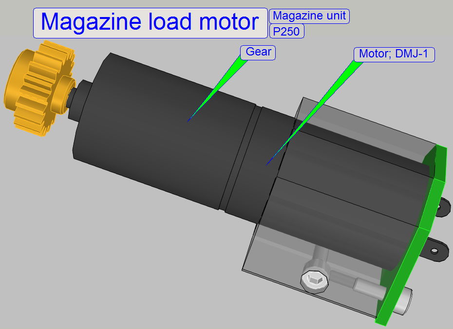 The
magazine loader motor is a
24V DC motor with directly connected gear and is switched on via software with
the button “Load
Magazine”. In the service program, this motor can be driven in forward and
backward direction respectively; the backward direction can be used for test
purposes only without a magazine in the input stack or in the magazine feeder
channel. The software uses the forward direction only, without exception.
The
magazine loader motor is a
24V DC motor with directly connected gear and is switched on via software with
the button “Load
Magazine”. In the service program, this motor can be driven in forward and
backward direction respectively; the backward direction can be used for test
purposes only without a magazine in the input stack or in the magazine feeder
channel. The software uses the forward direction only, without exception.
To increase the torque of the motor, a gear is
connected directly.
- The “Magazine load motor” does not need maintenance or adjustments.
The magazine load and unload part of the magazine unit
moves the magazines in vertical direction, from the magazine input stack onto
the magazine feeder rails and from the magazine feeder rails to the output
stack respectively. Both actions are realized with the same motor and
mechanical drive, so they are done always at the same time. Meanwhile the
actual (finished) magazine is moved upward to the output stack, the next
magazine (with slides to be inserted) is moved downward from the input stack
into the magazine feeder channel. This combined mechanical movement is always
done, even if the first magazine is being loaded or the last magazine had been
unloaded.
- The “Magazine load gear” does not need maintenance or adjustments.
Mounting
The magazine load gear is mounted together with the
magazine movement limiter to the base plate of the magazine feeder channel.
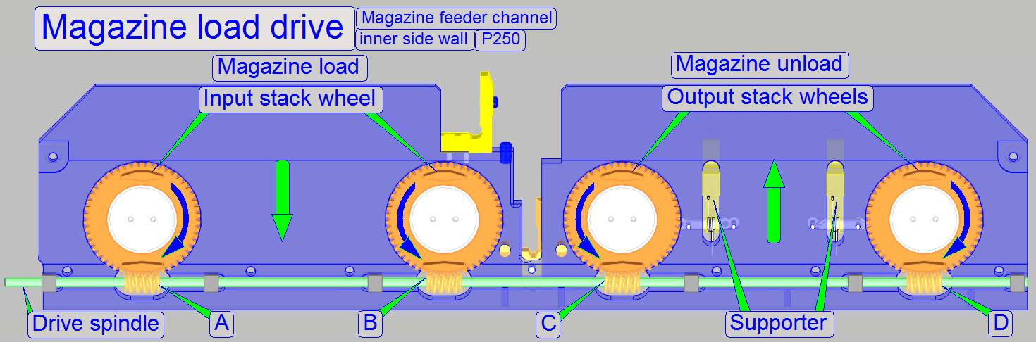 Input and output
stack wheels are situated on
both sidewalls of the magazine feeder channel and are driven by the worm
spindle so, that the output stack wheels moving the magazine upward during the
input stack wheels lowering down the magazine. To reach the opposite movement
of the stack wheels, the drive parts “A” and “D” of the worm spindle are
mounted in opposite direction (rotated by 180°) in relation to the drive parts “B”
and “C”. With this solution, the required movement of the stack wheels can be
reached.
Input and output
stack wheels are situated on
both sidewalls of the magazine feeder channel and are driven by the worm
spindle so, that the output stack wheels moving the magazine upward during the
input stack wheels lowering down the magazine. To reach the opposite movement
of the stack wheels, the drive parts “A” and “D” of the worm spindle are
mounted in opposite direction (rotated by 180°) in relation to the drive parts “B”
and “C”. With this solution, the required movement of the stack wheels can be
reached.
- The Stack wheels do not need maintenance.
- By adjusting the
magazine load sensor position, the correct stop position of the stack
wheels can be found.
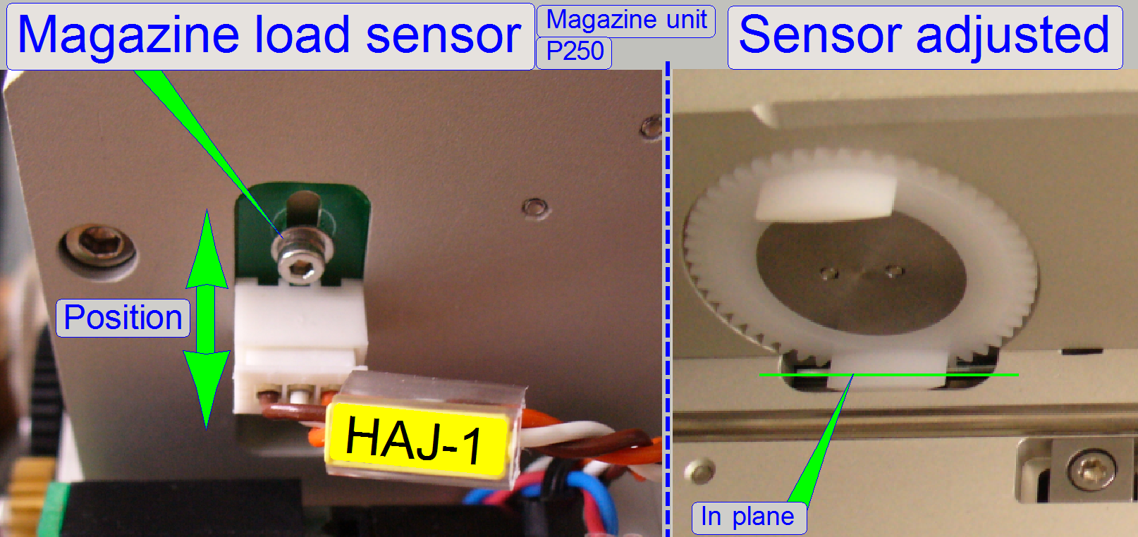
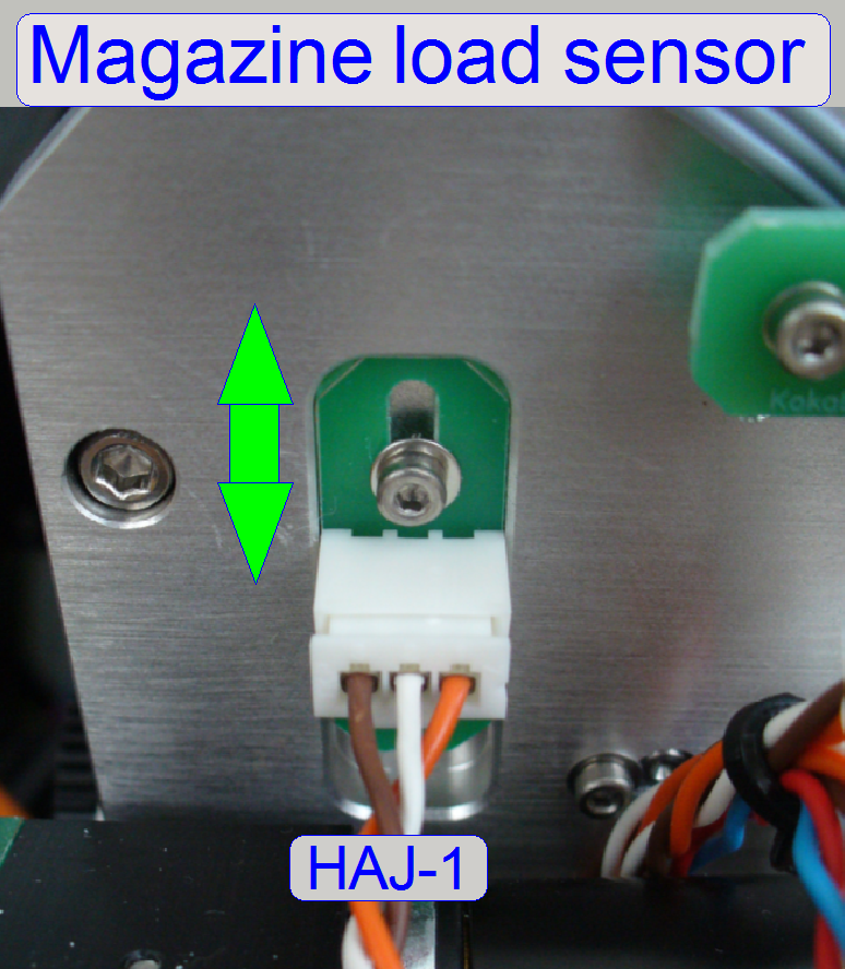
The magazine input stack
wheel, situated behind the sensor HAJ-1, contains two permanent magnets in a distance
of exact 180 degrees in relation to each other.
The sensor senses so a half revolution of the “Input
and Output stack wheels”.
After loosening the sensor’s mounting bolt, the sensor
can be moved upward or downward respectively. The right sensor position is
found if the stack wheels are in vertical position and the sensor is attached.
- The sensor does not need maintenance.
Hall sensors
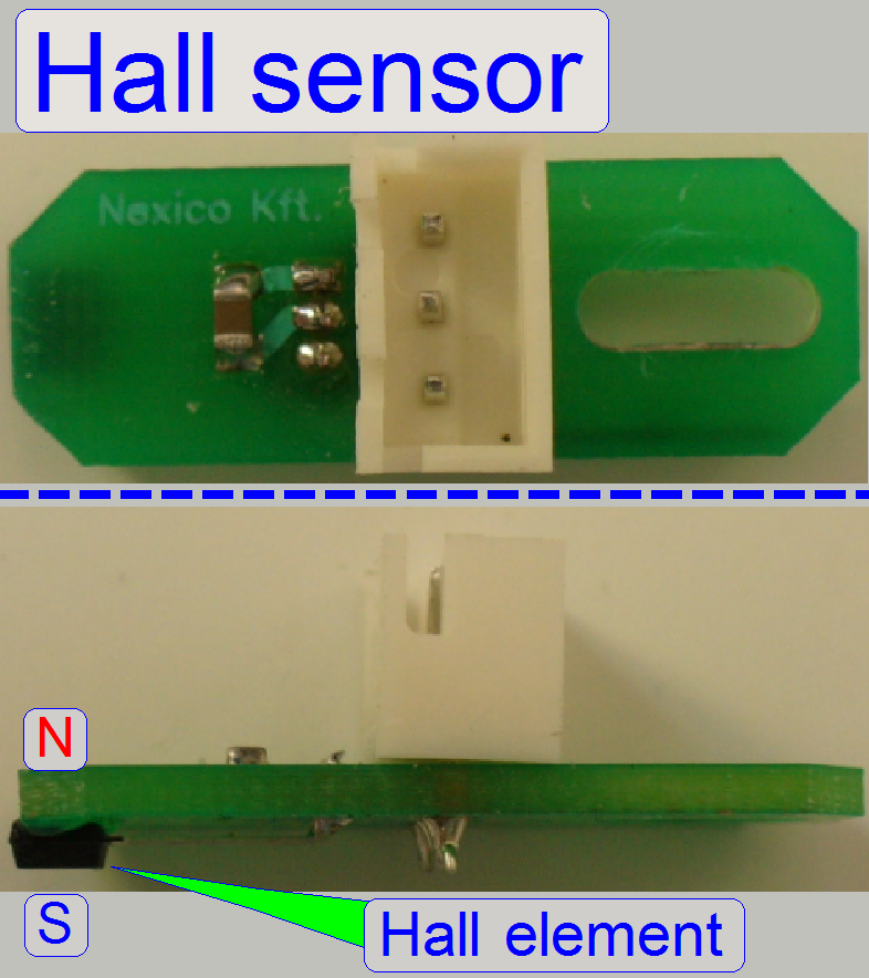
The “Magazine Loader Sensor” and the “Magazine Feeder
Sensor” are realized with Hall elements. If the south pole of a magnet is over
the hall element the switch is closed and this state is recognized by the
software.
If the other polarity of the magnet is over the hall
element no action occurs.
- The sensor position is adjustable. For adjustment procedures see
the appropriate chapters.
- The sensor does not need maintenance.
- The input and output stack sensors are also realized with Hall
elements, but their position cannot be adjusted.
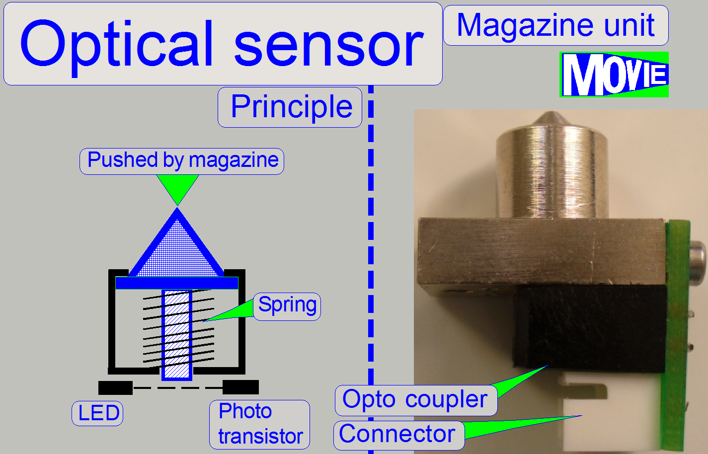 If the optical
sensor is pushed by the magazine, the light path between LED and photo
transistor will be broken by a pin. This action is recognized by the software.
If the optical
sensor is pushed by the magazine, the light path between LED and photo
transistor will be broken by a pin. This action is recognized by the software.
- The sensor positions are fixed and they are situated on the
magazine feeder channel bottom plate. The sensors do not need adjustment.
- The sensors should be kept clean. Because the action path is very
short, even small glass shards or dust is able to prevent the sensor from
correct switching.
![]() “Optical sensor”, “How to exchange the optical
sensor”
“Optical sensor”, “How to exchange the optical
sensor”
Magazine input sensor (left magazine sensor)
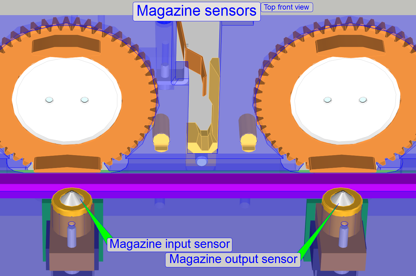
This sensor is used to detect a magazine in the
magazine feeder channel, after a magazine load procedure is finished. Even the
weight of an empty magazine should be able to push this sensor.
In opposite to the SCAN 150 the task and actions of
this sensor are modified.
- If the magazine arrives onto the feeder rails, the sensor may be
pressed or not until the position “Stop forward” of the magnet
disc is reached. The software checks the sensor state and decides now
the presence of the magazine. If a magazine is present, the feeder will
feed the magazine until the appropriate slide position is present at the
slide loading position; this is mostly the 1st slide position
of the magazine.
- If the position “Stop forward” of the magnet
disc is reached and the sensor is not pressed, the software detects
the state “No magazine in the feeder channel” present and aborts all
further actions.
![]() “How to exchange the optical
sensor”
“How to exchange the optical
sensor”
Magazine output sensor
(right magazine sensor)
This sensor is used to detect the correct unload
position for the magazine. The sensor is pushed and will be released if the
magazine is moved to the right (forward). If the software recognized, that the
sensor is released, a turn backward follows (the magazine is moved to the
left). If now the sensor is pressed again, the right magazine unload position
is found and the unload procedure is started, otherwise the software recognizes
“magazine jamming occurred” if the time out of the feeder gear is run out.
![]() “How to exchange the optical
sensor”
“How to exchange the optical
sensor”
1.
If the program SlideScanner.exe starts up,
the following actions are done:
a.
The slide loader is moved backward, to the
outer fixing position.
b.
The feeder gear had done at least one turn
backward; the magnet disc stays in the magazine load position (“Stop
backward”); see also “The magnet disc”.
2.
The magazine load procedure is started via
SlideScanner.exe (or the service
program) with the button “Load Magazine”.
3.
The magazine load motor and the input
stack wheels are driven forward and the magazine moves downward to the magazine
feeder rails. At the same time, the magazine (if any) is moved from the feeder
channel to the output stack.
4.
If the magazine input stack wheels have
done a half turn, the magazine
load sensor will be attached and the software will switch off the magazine
load motor.
5.
The magazine input sensor may be pressed or not, the
software changes the position of the magnet disc
from “Stop backward” to “Stop forward” first, before the state of the magazine
input sensor is checked!
If the magazine
input sensor (“Left magazine sensor”) stays attached, the magazine will be feed
to the first slide load position.
If the magazine
input sensor stays released, the state “Magazine not present” will be detected
and all further operations are aborted.
6.
Now the magazine is moved to the actual slide position, shown by the slide
position selector of the SlideScanner.exe.
7.
If the last slide to be scanned had been
removed into the magazine, the magazine feeder gear moves the magazine to the
right (forward), until the magazine output sensor was released.
8.
The software counts the pulses of the
magnet disc of the magazine feeder and checks always the state of the right
hand sensor (Magazine output sensor).
9.
If the state of the magazine output sensor
is released, a turn backward (the magazine moves to the left) follows and the
magazine output sensor is checked again.
10. If the
sensor is pressed, the magazine load motor is started, the output stack wheels
rotates for a half turn and moving so the magazine into the output stack; in
the same time the next magazine (if any exists) is moved from the input stack
onto the feeder rails.
11. After
the feeder gear reached the position “Stop forward”, the software checks the
magazine input sensor (left magazine sensor). If it is not attached (see also
the part “The Magazine input sensor”), the magazine load
/ unload procedure is finished; otherwise go to step 6 of the “magazine load
procedure”.
Watch video: Magazine load_P250
Magazine unload_P250
 The
magazine feeder gear of the magazine unit moves the magazine in the feeder
channel in horizontal direction, to the desired slide position forward or
backward as desired or to the magazine unload position. If the magazine was
just loaded, the magazine will be moved automatically (controlled by software)
to the first slide position of the magazine. The distance of the slide
positions in the magazine is exactly 2 revolutions of the feeder spindle. If a
previous position should be reached, the feeder spindle rotates one revolution
more backward as required, and then a forward revolution is followed.
The
magazine feeder gear of the magazine unit moves the magazine in the feeder
channel in horizontal direction, to the desired slide position forward or
backward as desired or to the magazine unload position. If the magazine was
just loaded, the magazine will be moved automatically (controlled by software)
to the first slide position of the magazine. The distance of the slide
positions in the magazine is exactly 2 revolutions of the feeder spindle. If a
previous position should be reached, the feeder spindle rotates one revolution
more backward as required, and then a forward revolution is followed.
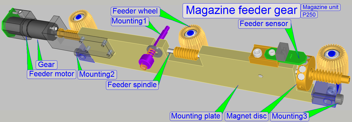
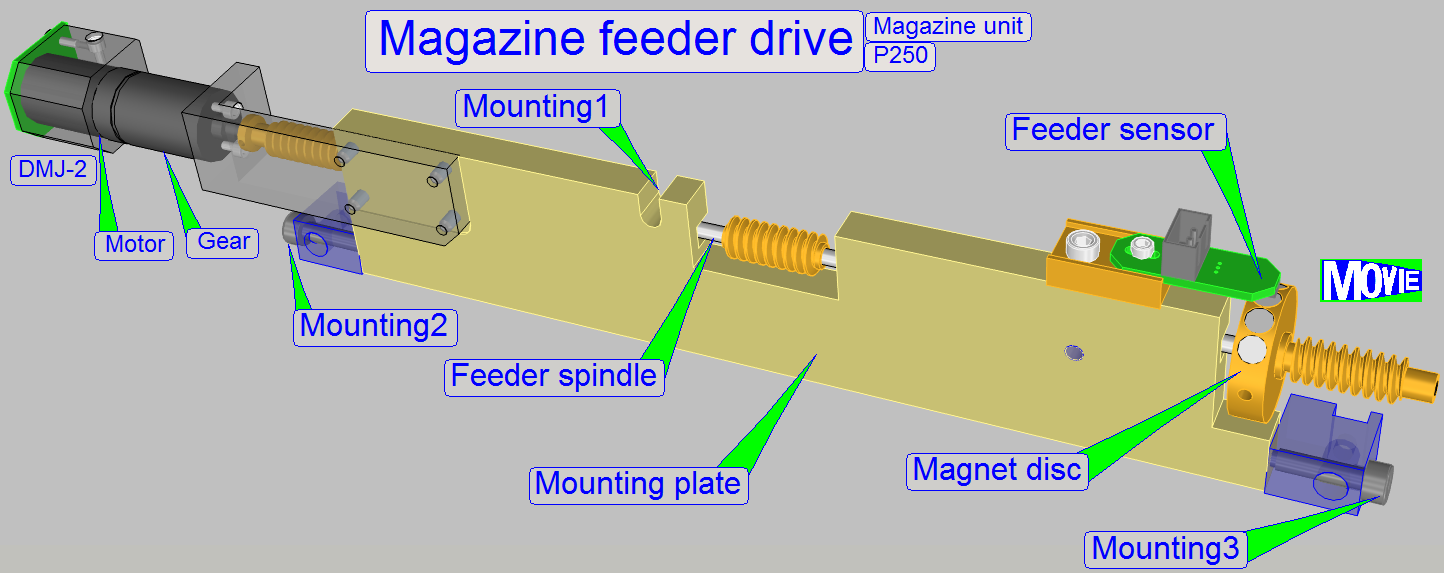
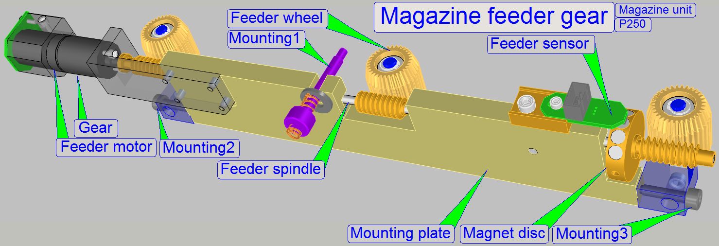
The magazine feeder unit
consists of
- Magazine feeder unit mounting.
- Magazine
feeder motor.
- Feeder
gear mounting plate with the worm spindle and the mounting bolt with
spring.
- Magnet
disc with the feeder sensor.
- Feeder
wheels; they drive the rack of the magazine.
- Feeder
rails, they ensure a smooth and evenly movement of the magazine.
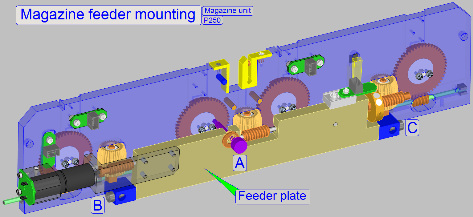 The Feeder unit mounting is
realized on three points, A, B, and C.
The Feeder unit mounting is
realized on three points, A, B, and C.
On the points B and C The mounting plate may be
rotated downward to disconnect the feeder gears.
The mounting A is realized with a spring. The force of
the spring guarantees the proper connection of the drive spindle to the feeder
wheels. With this solution the feeder drive unit may be disconnected from the
feeder wheels if magazine jamming occurs, overload of the motor is avoid.
 The
mounting bolt (Mounting1) together
with the force of the spring guarantees the optimal connection between worm
spindle and feeder wheels during feeding. This solution protects the motor from
overload also, if magazine jamming occurs in the magazine channel during
magazine feeding. The spring should not be stretched or shortened!
The
mounting bolt (Mounting1) together
with the force of the spring guarantees the optimal connection between worm
spindle and feeder wheels during feeding. This solution protects the motor from
overload also, if magazine jamming occurs in the magazine channel during
magazine feeding. The spring should not be stretched or shortened!
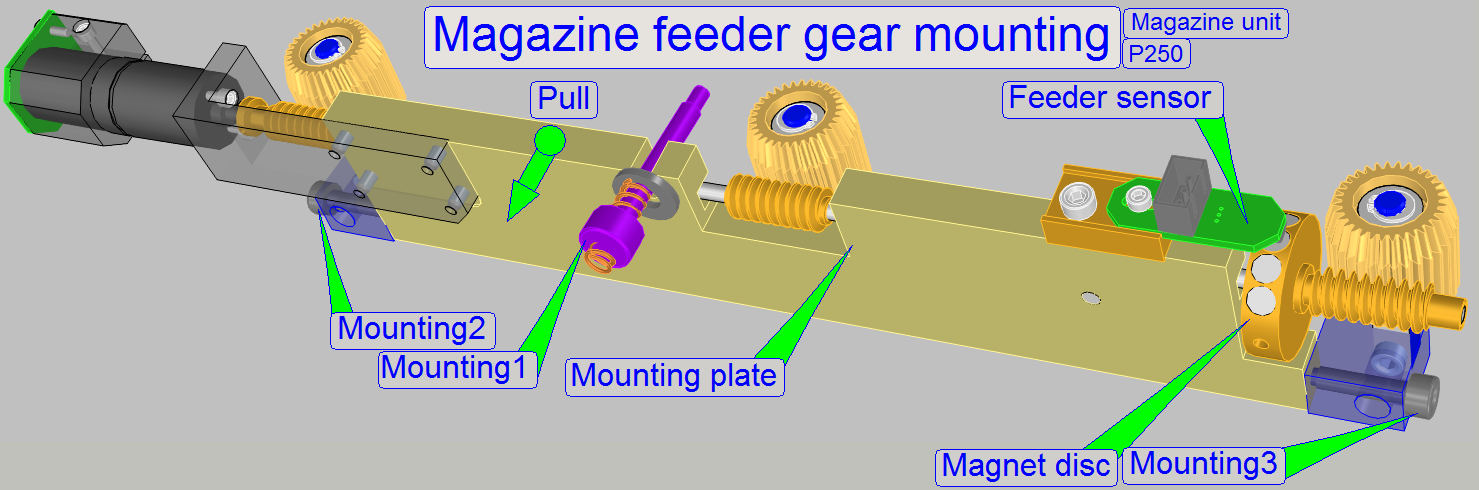
· By
disconnecting the drive unit from the feeder wheels, the magazine becomes
manually moveable in the feeder channel (pull the mounting plate frontward).
Pull the mounting plate frontward
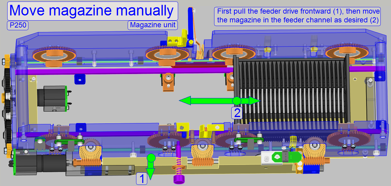
During adjustments, checks
and services, the feeder drive unit can be disconnected manually from the
feeder wheels and so the magazine becomes manually moveable in the magazine
feeder channel.
By pulling the mounting
plate frontward, the compression spring of the mounting bolt
will be pressed, the drive of the feeder wheels is disconnected and so:
- The magazine can be shifted to any desired slide position manually.
- The magazine can be removed from the magazine channel manually by
shifting the magazine to the right and
- The magazine can be inserted into the magazine feeder channel
manually from the right side.
If the mounting plate is released again, the right
connection between worm spindle and feeder wheels should be checked by rotating
all three feeder wheels a little bit or you can issue the “Magazine Feeder” command via the service program.
- The “Magazine feeder gear” does not need maintenance.
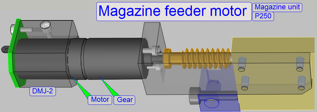 The magazine
feeder motor is a 24V DC motor and it is switched on
via software to reach the desired slide position, the first slide position
after magazine load or to reach the magazines unload position. With the
software (SlideScanner.exe or SlideScannerService.exe) the backward direction
of this motor is used to reach previous slide positions also.
The magazine
feeder motor is a 24V DC motor and it is switched on
via software to reach the desired slide position, the first slide position
after magazine load or to reach the magazines unload position. With the
software (SlideScanner.exe or SlideScannerService.exe) the backward direction
of this motor is used to reach previous slide positions also.
To increase the torque of the motor, a gear is
connected directly. The transmission of this gear is different to the gear of
the magazine loader motor.
- In opposite to the scan 150, the gear of this motor has another
transmission, so the magazine is fed more slowly in the P250.
- The “Magazine feeder motor” does not need maintenance or adjustments.
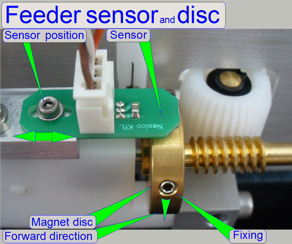
 The magazine feeder gear moves
the magazine in the feeder channel via the worm spindle and the feeder wheels.
Because the position of the feeder wheels during the magazine load action is different
from the position during the slide load action, the magnet disc contains four
permanent magnets (in previous versions two permanent magnets); it is situated
near the end of the worm spindle. One revolution of the worm spindle moves the
magazine a half slide position. To reach the next slide position, exactly two
revolutions of the worm spindle is needed. The first magnet of the magnet disc initiates a pulse via the
sensor to the software after each revolution of the worm spindle. The pulse is
used to switch off the motor. For slide insert actions always and only the
forward stop position of the feeder gear is used. The magazine load action is
always done in the backward stop position. If previous slide positions should
be reached, the worm spindle is turned backward one turn more as necessary, and
then a forward turn of the feeder gear follows to fulfill the requirement.
Please take this into account if you are adjusting the slide insert / removal
position with the service program!
Before a magazine load procedure is done, the magnet disc should be in the start
position, otherwise the cogs of the magazine rack and the cogs of the feeder
wheels will not engage.
The magazine feeder gear moves
the magazine in the feeder channel via the worm spindle and the feeder wheels.
Because the position of the feeder wheels during the magazine load action is different
from the position during the slide load action, the magnet disc contains four
permanent magnets (in previous versions two permanent magnets); it is situated
near the end of the worm spindle. One revolution of the worm spindle moves the
magazine a half slide position. To reach the next slide position, exactly two
revolutions of the worm spindle is needed. The first magnet of the magnet disc initiates a pulse via the
sensor to the software after each revolution of the worm spindle. The pulse is
used to switch off the motor. For slide insert actions always and only the
forward stop position of the feeder gear is used. The magazine load action is
always done in the backward stop position. If previous slide positions should
be reached, the worm spindle is turned backward one turn more as necessary, and
then a forward turn of the feeder gear follows to fulfill the requirement.
Please take this into account if you are adjusting the slide insert / removal
position with the service program!
Before a magazine load procedure is done, the magnet disc should be in the start
position, otherwise the cogs of the magazine rack and the cogs of the feeder
wheels will not engage.
The feeder wheels are driven by the worm spindle from
the outer side, during on the inner side of the feeder wheel the magazine rack
is driven.
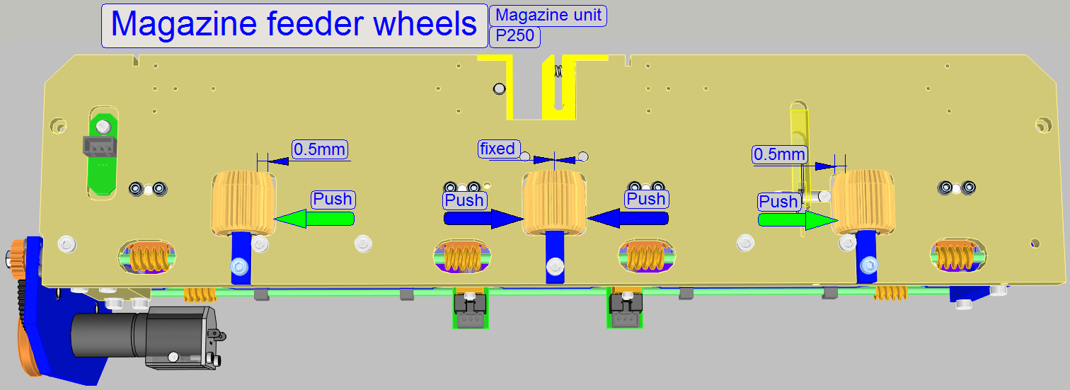 To prevent a mechanical shorting
during magazine movements in the feeder channel if the magazine connects the
middle feeder wheel or the feeder wheel on the right, the left and right sided
feeder wheels are not fixed in their positions; these are fixed with springs,
inside the wheel mounting.
To prevent a mechanical shorting
during magazine movements in the feeder channel if the magazine connects the
middle feeder wheel or the feeder wheel on the right, the left and right sided
feeder wheels are not fixed in their positions; these are fixed with springs,
inside the wheel mounting.
The acting range of the left and right handed feeder
wheels is about 0.5mm. The acting direction is always outward; it means, the
left feeder wheel has the acting direction to the left and the right handed
feeder wheel has its acting direction to the right.
To ensure a stable slide loading position of the
magazine, the feeder wheel in the middle is fixed and has no acting range.
- If magazine feeder jamming occurs often (if the magazine rack drive
changes from the left to the middle feeder wheel or the drive changes from
the middle to the right sided feeder wheel), check the acting range and
the acting direction of the feeder wheels!
- To check this, please remove the mounting bolt with spring,
disconnect the feeder sensor and rotate the feeder unit mounting plate
downward.
Important
- If the acting direction of any feeder wheel is different or there
is no acting range, a shorting of
the mechanics of the feeder drive unit occurs (magazine jamming) and
the feeding of the magazine will
never work correctly.
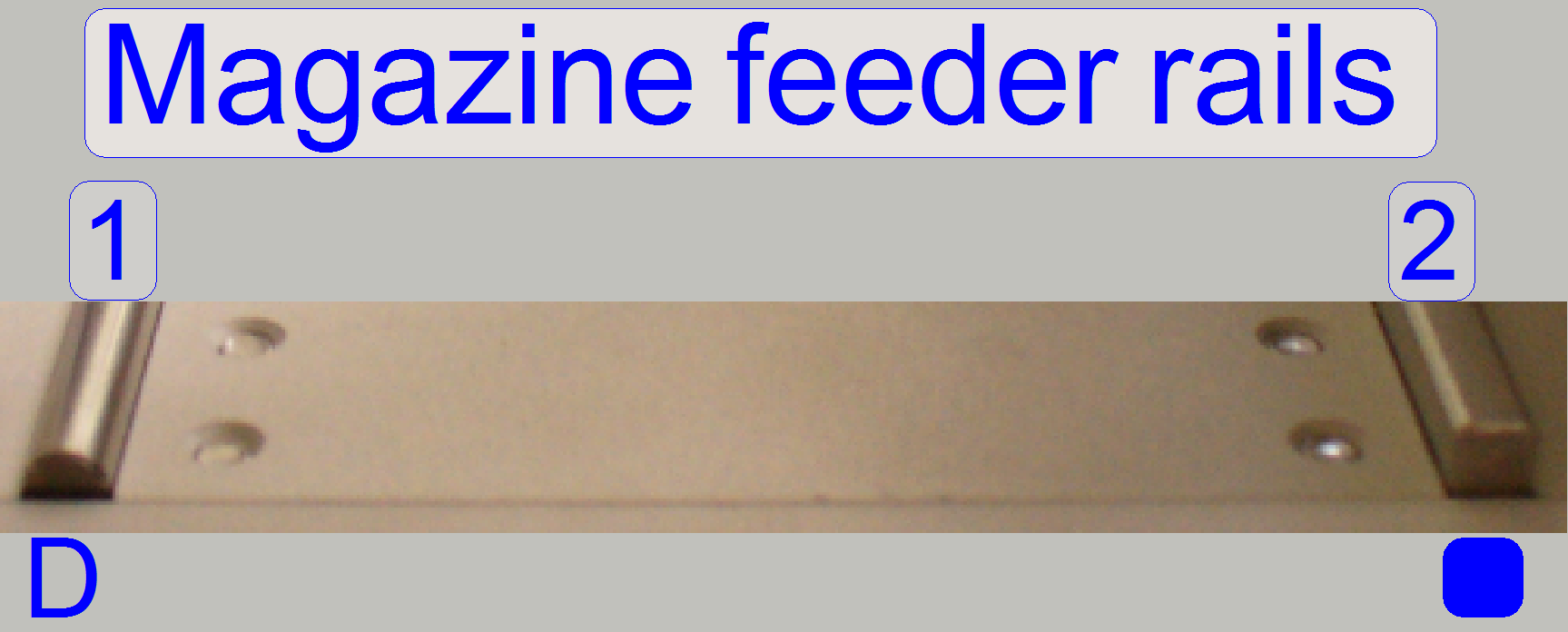
The magazine feeder rails are
different in shape, because the magazine is driven only on the back side of the
magazine by the magazine feeder wheels. To ensure very small skin resistance
during feeding on the non driven side of the magazine, the inner rail (1) has a
D-shape; in older versions it may be an O-shape. To lead the magazine during
feeding and to ensure stable movement of the magazine, the outer rail (2) has a
square profile.
- The rails should be kept clean and dry.
- The magazine feeder rails do not need adjustment.
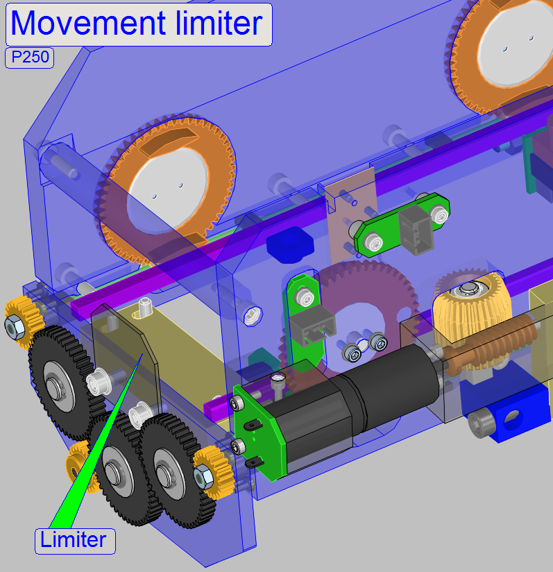
- On the left side of the magazine feeder channel
bottom plate a magazine movement limiter is realized to prevent the
brightfield scan camera if wrong magazine movement is executed (might be
done with the service program).
Mounting
The magazine movement limiter is mounted together with
the magazine load gear to the base plate of the magazine feeder channel.
To adjust the magnet disc position in relation to the
spindle and so, in relation to the magazine position, the fixing must be
loosened.
To reach the correct stop position of the magnet disc use the
rising edge of the sensor action.
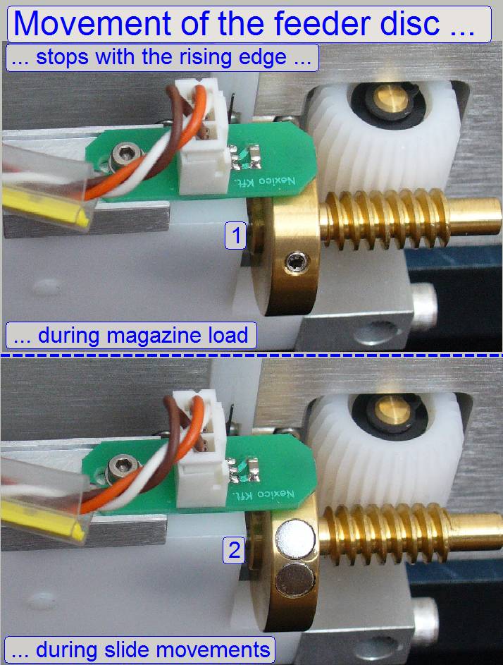
The magnet disc position is in connection with two
actions, both depending on the right adjustment:
- Magazine load action
The position of
the cogs of the magazine rack and the cogs of the left sided feeder wheel
should allow the cogs to match up; so the magazine can move downward smoothly and
evenly. If the magazine arrived onto the feeder rails, and the magnet disc is
in the stop forward position (slide insert position) the left magazine (input) sensor should be
pressed. The correct start position of the magnet disc for the magazine load
procedure is found by rotating the magazine feeder gear backward until the position “Stop backward” is
reached (with the service
program); see also (1) on the right.
Watch video: Magnet
disc during magazine load_P250
Magnet
disc during magazine unload_P250
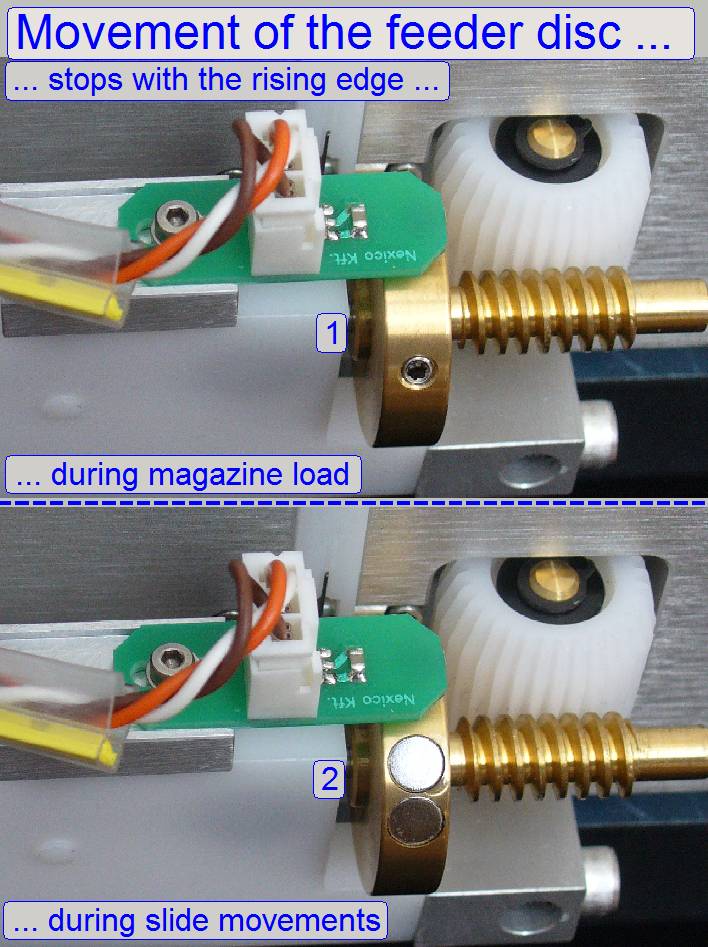 Slide insert and removal action
The correct
magazine position for the slide insert and removal action is also found by
adjusting the “Magnet disc” position. The slide loader outer finger should be in
the middle of the magazine rail. The correct position of the magnet disc for
the slide load procedure is found by rotating the magazine feeder gear forward
until the position “Stop forward”
is reached (with the service
program); see also (2) on the right.
The magnet disc stop position should be anywhere
behind the second magnet and the sensor should not signal
(SlideScannerService.exe, DC controller, Sensor state, Magazine feeder= X). It
is important that after each turn of the feeder spindle, the stop position of
the disc should be always the same, if the option “Stop with sensor” is
selected. To reach this requirement, the position of the sensor in relation to
the magnet disc can be adjusted in a small range.
The detailed adjustment procedure is described later.
- The magnet disc and the sensor do not need maintenance.
Watch video: Magnet
disc during magazine load_P250
Magnet
disc during magazine unload_P250
Sensor disc modified; since 2014
Working
principle
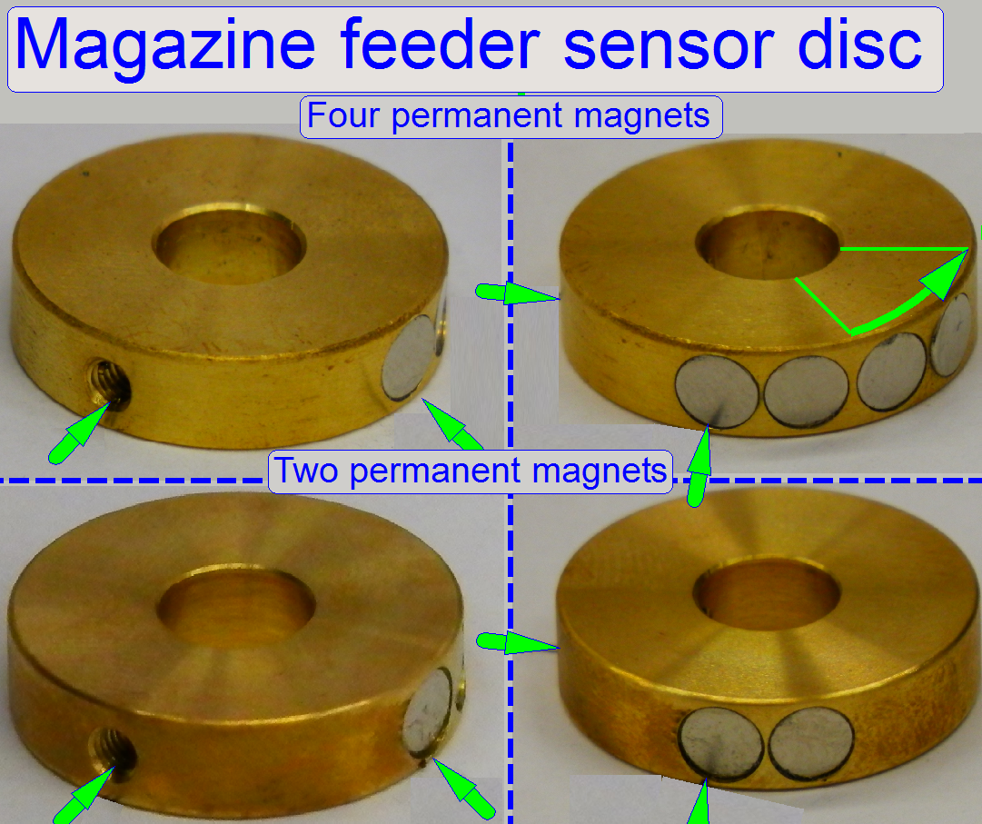
By implementing 2 further permanent magnets into the
existing magnet disc, the stability of the recognition of the magazine presence
in the feeder channel is improved. While the slide insert position remains
unchanged; the left magazine sensor will be surely attached if a magazine is
present.
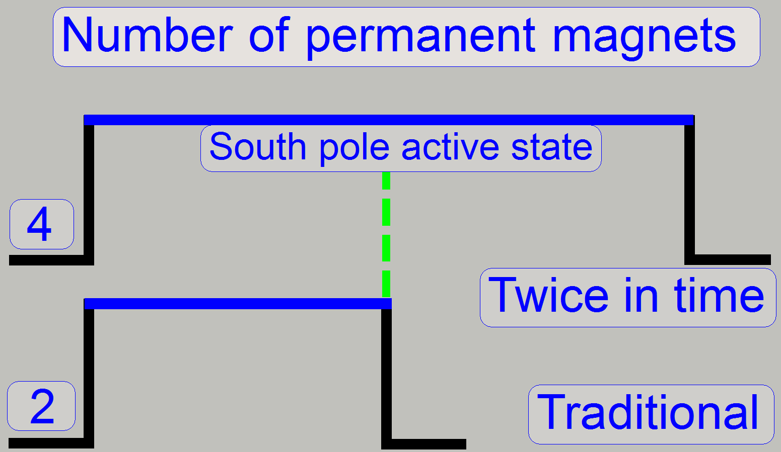
With this solution, the south pole of the permanent
magnets stays longer in time (twice) over the feeder sensor.
· The
sensor “sees” the two or four permanent magnets as a unit of one permanent
magnet; the signal is not pulsed!
The exchange of the magnet disc requires adjustments
regarding the slide insert position and the magazine load position!
· Adjust
always the slide insert position first, and then check the magazine load action
in relation to the found slide insert position.
The disc modification or exchange does not require
software modification; so the upgrade may be executed regardless the software
version.
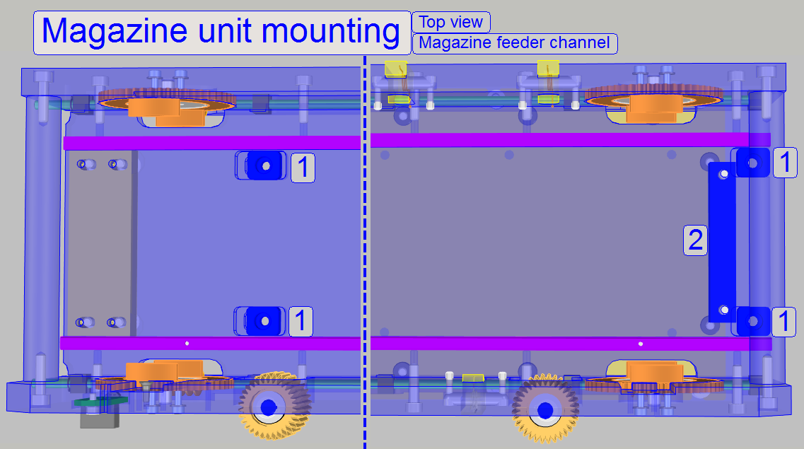
These four bolts with washers mount the entire
magazine unit to the truss. These bolts should be loosened a little bit to make
the magazine unit moveable only during the magazine unit position adjustment
procedure, otherwise they are always tightened.
Magazine unit position adjustment
 Adjust the slide leading edge
position to the position of the specimen holder
Adjust the slide leading edge
position to the position of the specimen holder
- For this adjustment the specimen holder fixing fork's mounting and
the magazine unit mounting should be barely loosened!
Loosen the magazine unit mounting bolts a little bit
to make the magazine unit moveable.
Loosen the Specimen holder fixing fork's mounting
bolts a bit, so the fixing fork becomes also moveable.
With the position adjustment (2) and the position
fixing bolt (3) the entire magazine unit can be moved to the left or to the
right to find the correct position for the slide position guide in relation to
the specimen holder.
The position fixing bolt should be loosened if the
position adjustment bolt is turned clockwise; the entire magazine unit moves to
the left.
If the position adjustment bolt is turned counter
clockwise (loosened), the entire magazine unit can be moved to the right by
carefully tightening the position fixing bolt.
If the adjustment is finished, the position adjustment
bolt should touch the magazine unit and the position fixing bolt should be even
tighten. With this solution the adjusted position is not lost and the correct
position of the magazine unit is found again, if the entire magazine unit was
removed.
1.
Remove the cable HMJ-1 from the slide
loader and remove the entire slide loader also.
2.
Remove the cable DCJ-1 from the DC
controller unit.
3.
To remove the cover of the magazine unit position
adjustment, remove the bolt (3) and loosen respectively the bolt (2); the cover
can be moved downward. Barely loosen the adjustment fixing bolt a little bit.
4.
Remove the mounting bolts (1) for the
magazine unit.
5.
Move the entire magazine unit upward.
1.
Place the magazine unit onto the truss and
push it to the right, until the “Position adjustment bolt” is reached.
2.
Insert the mounting bolts with the washers
(1) and push the entire magazine unit to the right until the “Position
adjustment bolt” is reached, then tighten the mounting (1) carefully;.
3.
Connect the cable DCJ-1 for the DC
controller unit.
4.
Insert the slide loader and connect the
cable HMJ-1.
5.
Adjust the magazine loader as described in
“Adjust the magazine load mechanics”.
6.
Adjust / check the magazine unit position
as described in “Define the slide insert and removal positions”.
7.
Mount the cover of the magazine unit
position adjustment.
8.
Execute the magazine loading test and the
slide loading test of the program “SlideScanner.exe” with different magazines
and different slide sizes, slide shapes also.
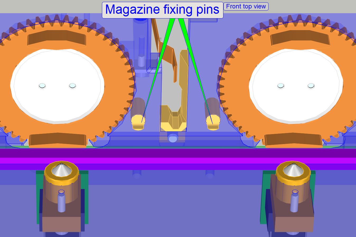
The magazine fixing pins are fixing the position of
the magazine during slide insertion and slide removal.
- They need no adjustment or maintenance.
Adjust
magazine load mechanics
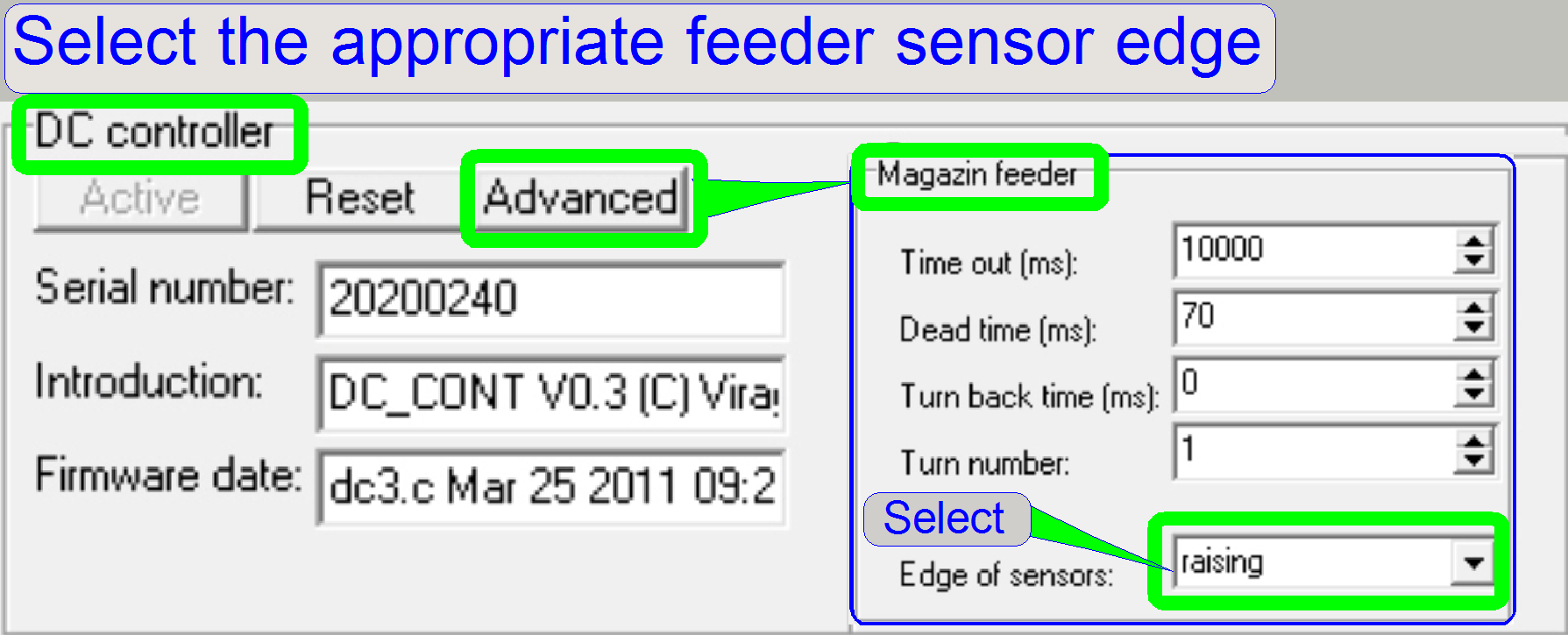
1.
Start the service program
SlideScannerService.exe and switch active the section “Low level service” and
“DC controller”.
2.
In the tab „Advanced”, section “Magazine
feeder” check or select the “Edge of the sensor” for or to the option “raising” and close the dialogue
“Advanced” with OK!
- In opposite to early versions of the SCAN
3.
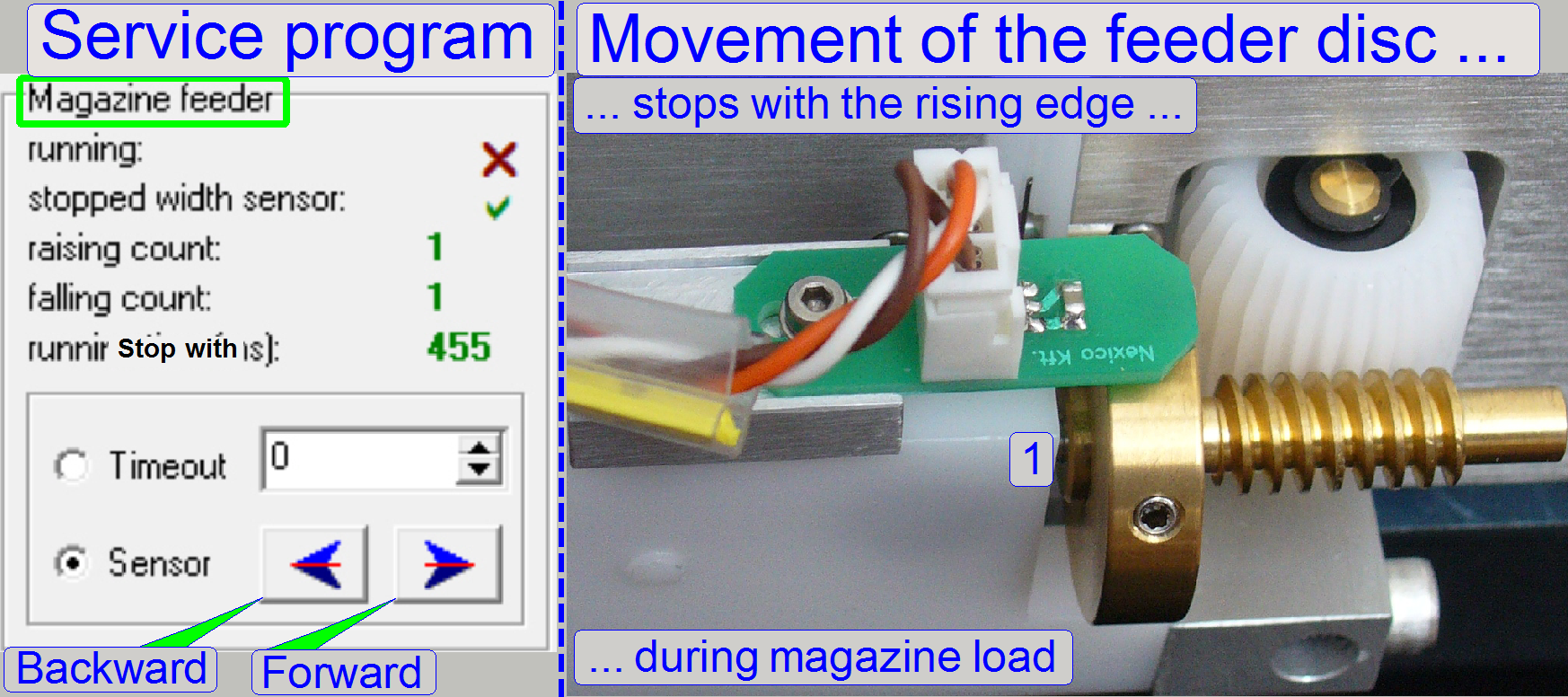 With the “Magazine feeder” backward button
the feeder gear brings the magnet disc into the start position for the magazine
load operation (1).
With the “Magazine feeder” backward button
the feeder gear brings the magnet disc into the start position for the magazine
load operation (1).
Watch video: Magnet
disc during magazine load_P250
Magnet
disc during magazine lunload_P250
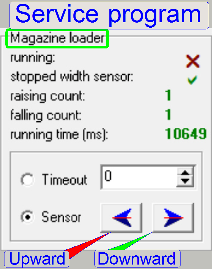
4.
With the “Magazine loader” forward button
and no magazine in the input stack, bring the magazine input and output stack wheels
into the start position.
Remark
Upward and downward is related to the input stack.
Important
·
Use the direction "Upward"
carefully, magazine stumble may occur if the position of the magazine is
incorrect!
5.
Check the “Magazine loader” sensor state
and the “Magazine Feeder” sensor state, the loader state should be attached,
during the feeder state should be released.
6.
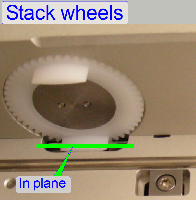
Check the stop position of the input and
output stack wheels.
7.
The stop position of the stack wheels
should be perpendicular, and in plane with the magazine channel bottom plate.
8.
Adjust the magazine loader sensor position
so, that this requirement (step 7) is reached, it is not a critical adjustment;
repeat steps 3 to 7 until the requirements are fulfilled.
9.
Insert a magazine into the input stack and
with the “Magazine loader” forward button start a magazine load. The magazine
should move smoothly and evenly downward, without stumble.
10. If
stumble occurs, the magazine feeder gear should be adjusted via the magnet disc so, that the cogs of the feeder
wheel and the magazine rack engages and do not disturb each other.
11. If the magazine arrives onto the feeder rails and the magnet disc
position had been changed from backward to forward (from the magazine load position
to the slide load position), the magazine input sensor should be pressed (see
also “Magazine input sensor”).
12. Adjust the position of the magnet disc so, that the magazine input
sensor is even pressed if the magnet disc had changed from “Stop backward” to
“Stop forward” (check the action with the shown sensor state (the left magazine
sensor) in the service program!).
13. Repeat the steps 7 to 9 several times and with different magazines. If
the requirements are fulfilled (no stumble during magazine load action and step
11 is fulfilled), the adjustment is finished.
14. Finally test the magazine load and unload procedure with all the 10
magazines, without slides. Observe the load procedure, the empty magazines
should move downward smoothly and evenly and the left magazine sensor should be pressed, if
the magazine arrives onto the feeder rails and the slide insert position of the
magazine is found (2).
 The slide loader is mounted on the magazine unit but is not
a part of the magazine unit; it is a separate spare part instead.
The slide loader is mounted on the magazine unit but is not
a part of the magazine unit; it is a separate spare part instead.
Nevertheless, if
the slide loader will be exchanged, special adjustments and corrections have to
be done before the slide loading operation works correctly.
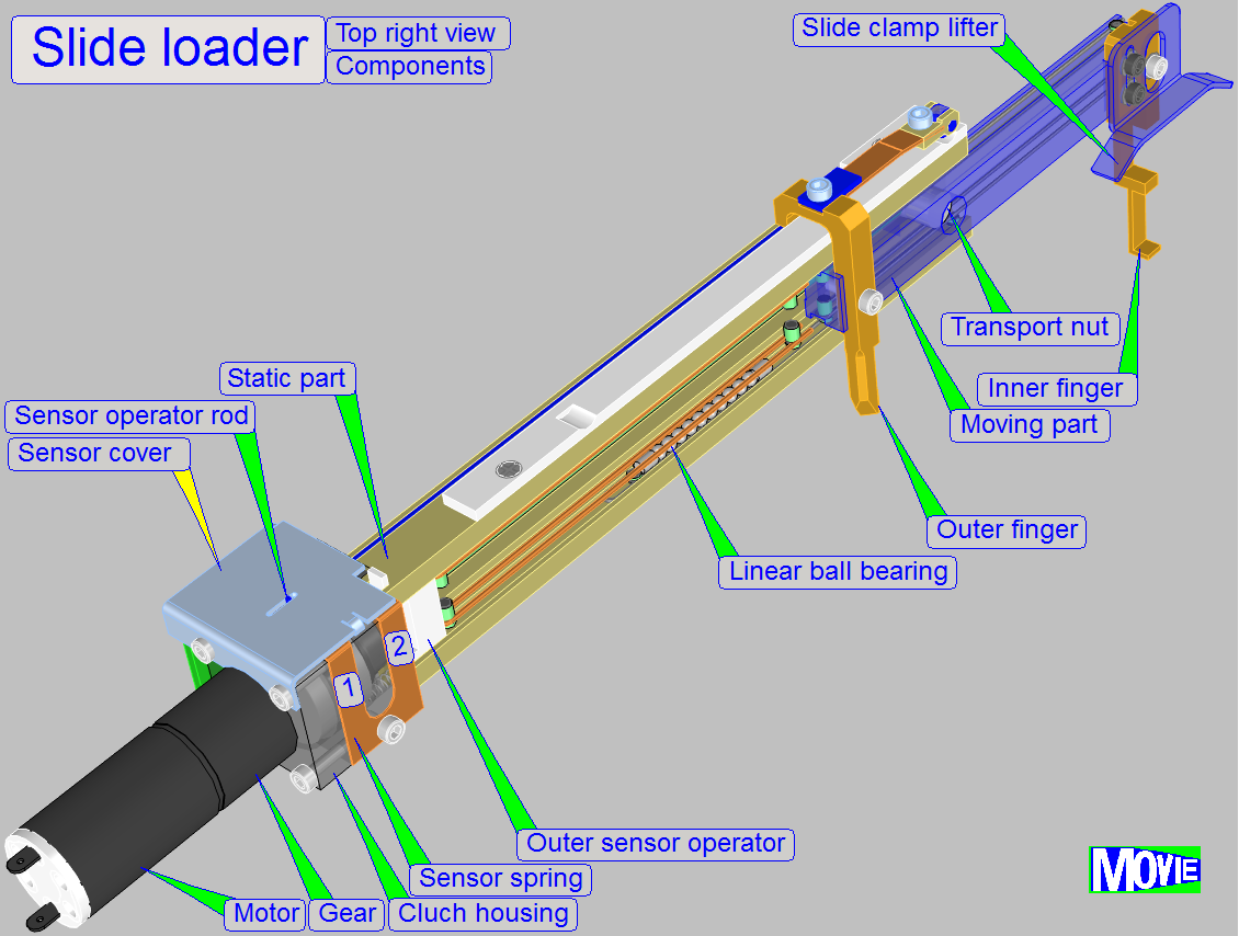
The DC motor drives
via a gear the spindle. In the clutch housing the connection
between gear and spindle is realized. This way, the inner and outer finger can
be moved into the specimen holder of the specimen holder to insert a slide, or
return, from the specimen holder to the slide position of the magazine, to
remove a slide.
Contents
Move
the slide loader moving part manually
Check
the functionality of the slide loader sensors
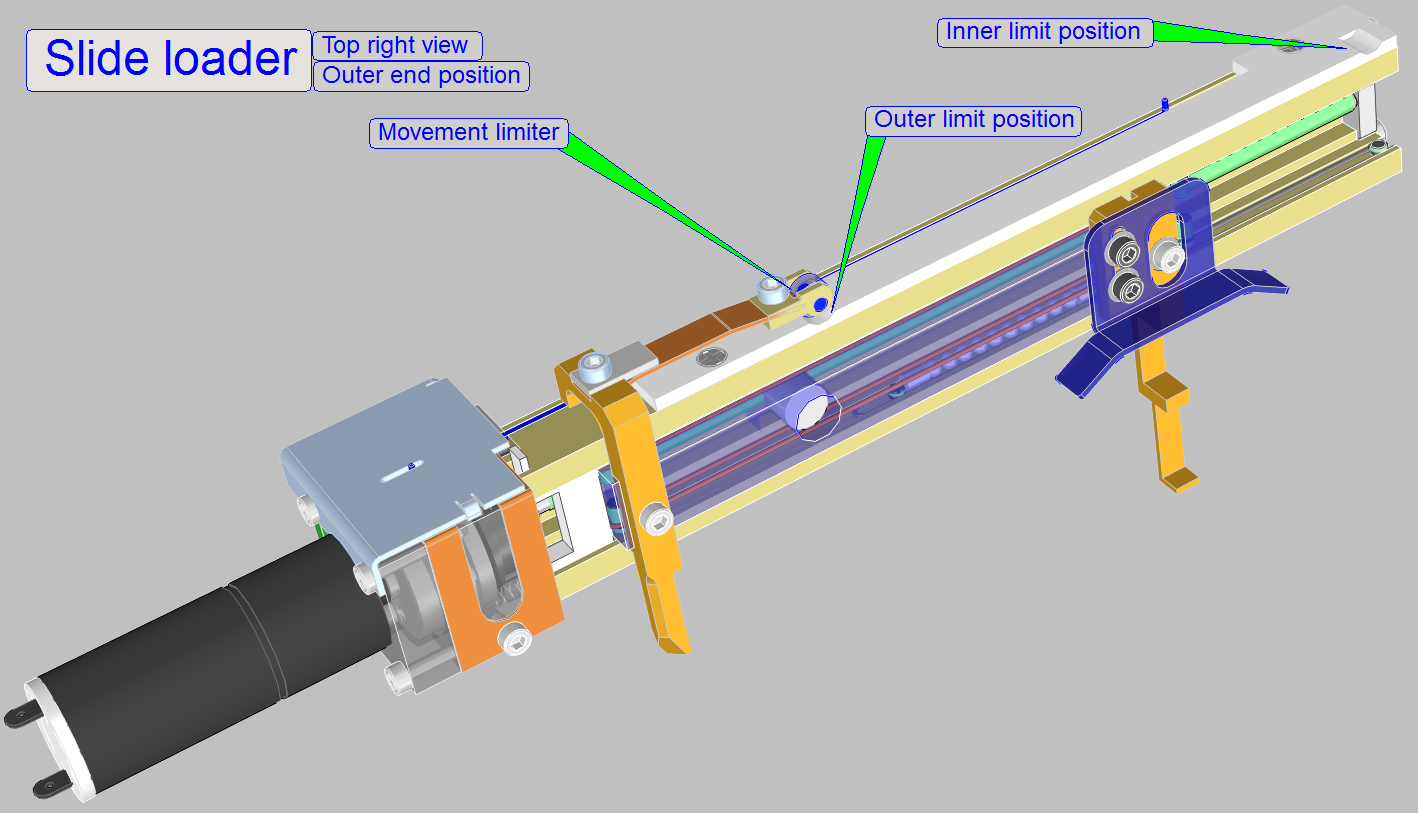
Because the mechanical construction has inertia, an inner and outer movement limit position was
realized. This solution eliminates the inertia and guarantees always the same
limit position for the inner and outer position of the slide loader moveable
part.
·
The slide loader movable part reaches
always the outer limit position, while the inner position fixing is a limiter
only; it is not a requirement that the inner position fixing is reached always.
Watch video: Slide insert P250
 The slide loader movable part has only two positions,
the inner and the outer position. The entire mechanics is constructed so, that
only these two positions are defined. The state “Inner position reached” is
signaled to a sensor via the “Sensor operating rod”. The inner and the outer sensors
are situated in the clutch housing, behind the sensor cover. The “Sensor
operating rod” removes the sensor magnet (situated on the sensor spring 1) from
the Hall element for the inner sensor.
The slide loader movable part has only two positions,
the inner and the outer position. The entire mechanics is constructed so, that
only these two positions are defined. The state “Inner position reached” is
signaled to a sensor via the “Sensor operating rod”. The inner and the outer sensors
are situated in the clutch housing, behind the sensor cover. The “Sensor
operating rod” removes the sensor magnet (situated on the sensor spring 1) from
the Hall element for the inner sensor.
This event is signaled to the software and the
software will switch off the DC motor, the inner position is reached.
If the moveable part of the slide loader moves
outward, from the inner position to the outer position, the magnet, situated on
the sensor spring 2 will be moved over its Hall element for the outer sensor;
this state is signaled to the software and the motor will be switched off. A
spring (not shown) in the outer end position moves the slide loader moveable
part into the “outer position fixing”; releases so the sensor and the final
outer position is reached.
·
During the inner sensor stays active if
the inner position is reached, the outer position sensor stays released when
the outer final position is reached.
 The slide loader should be hold at the
motor and / or the clutch housing, but please does not touch the sensor cover,
it can be deformed easily. The moveable part can be pulled on the mounting bolt
of the inner finger or pushed on the surface near to the inner or outer finger
mounting.
The slide loader should be hold at the
motor and / or the clutch housing, but please does not touch the sensor cover,
it can be deformed easily. The moveable part can be pulled on the mounting bolt
of the inner finger or pushed on the surface near to the inner or outer finger
mounting.
- To avoid deforming or misaligning of adjusted parts, other parts
should not be touched.
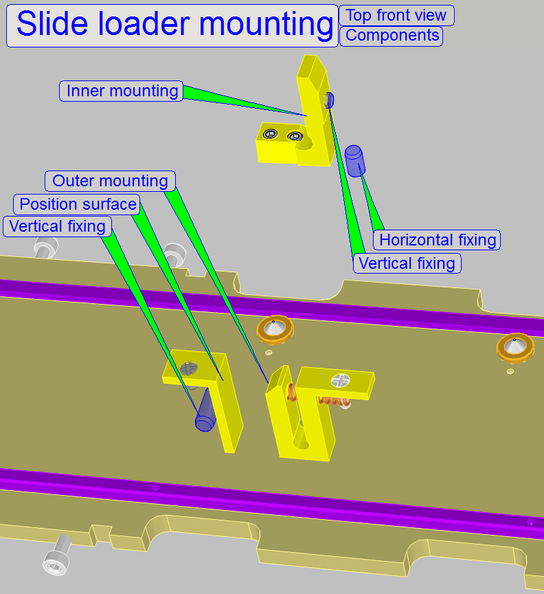
The slide loader is mounted on the two side walls of
the magazine channel as shown in the figures on the right.
Both mountings include a horizontal and a vertical
fixing for the slide loader position.
By moving the plastic holder a little bit sideward on
its upper end, the vertical fixing will be disconnected from the slide loader
inner mounting.
The exact horizontal position of the slide loader in
relation to the specimen holder is defined by adjusting the entire magazine
unit position with the “Magazine
unit mounting” and the “Magazine
unit adjustment” bolts respectively and was discussed above.
Because the “Slide loader inner finger” moves into the
specimen holder, it’s height in relation to the slide clamp (the vertical
position) must be adjusted also and will be discussed later.
1.
Disconnect the Slide loader cable “HMJ-
2.
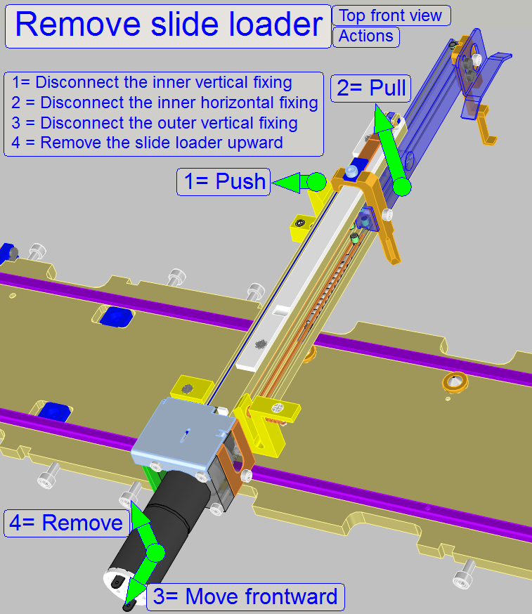 Move the slide loader moving part
into the specimen holder manually, until the inner finger stays behind the
slide clamp.
Move the slide loader moving part
into the specimen holder manually, until the inner finger stays behind the
slide clamp.
3.
Take the slide loader inner part from
below (the part named as “2. PULL upward”) with your right hand and push the
“Plastic Holder” (“1. PUSH”) with the thumb to the left a little bit, until the
“Vertical Position” fixing is disconnected.
4.
Now pull the inner part (2. PULL upward)
of the slide loader upward a little bit.
5.
Shift the entire slide loader backward to
disconnect the “Vertical fixing pin” of the “Slide loader mounting
6.
Now the entire slide loader can be removed
in upward direction.
7.
 Move the specimen holder to Y-home
1,2 and X-home 1,2.
Move the specimen holder to Y-home
1,2 and X-home 1,2.
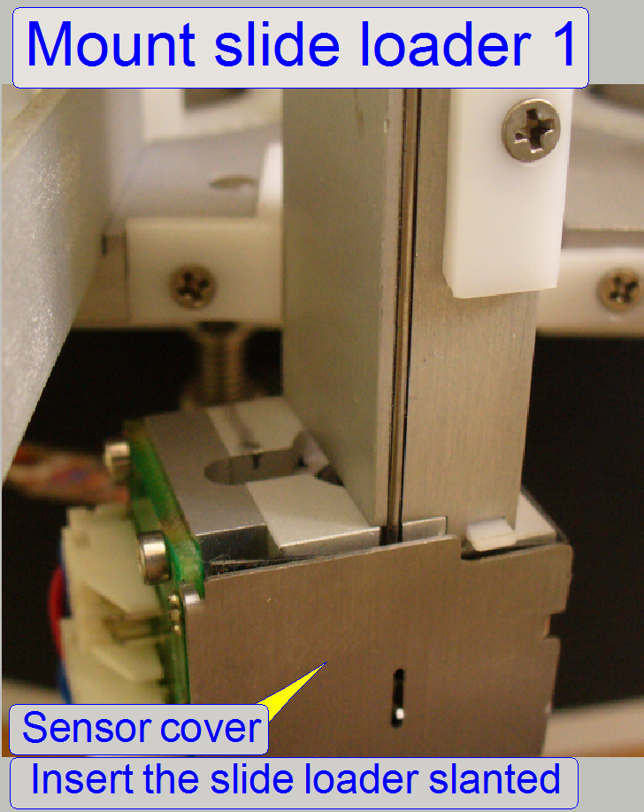
8.
Move the slide loader moveable part a
little bit toward to the inner end position. The inner finger should be behind
the “Slide clamp”, inside of the specimen holder.
9.
Fit the slide loader with the “Slide
loader mounting
10. 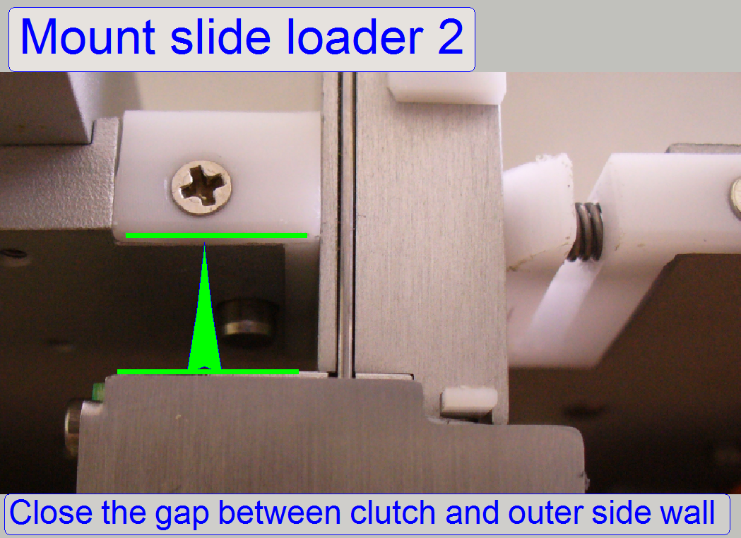 Close the gap between clutch housing and
magazine feeder channel wall so that the vertical fixing is connected.
Close the gap between clutch housing and
magazine feeder channel wall so that the vertical fixing is connected.
- Push the slide loader against the channel sidewall
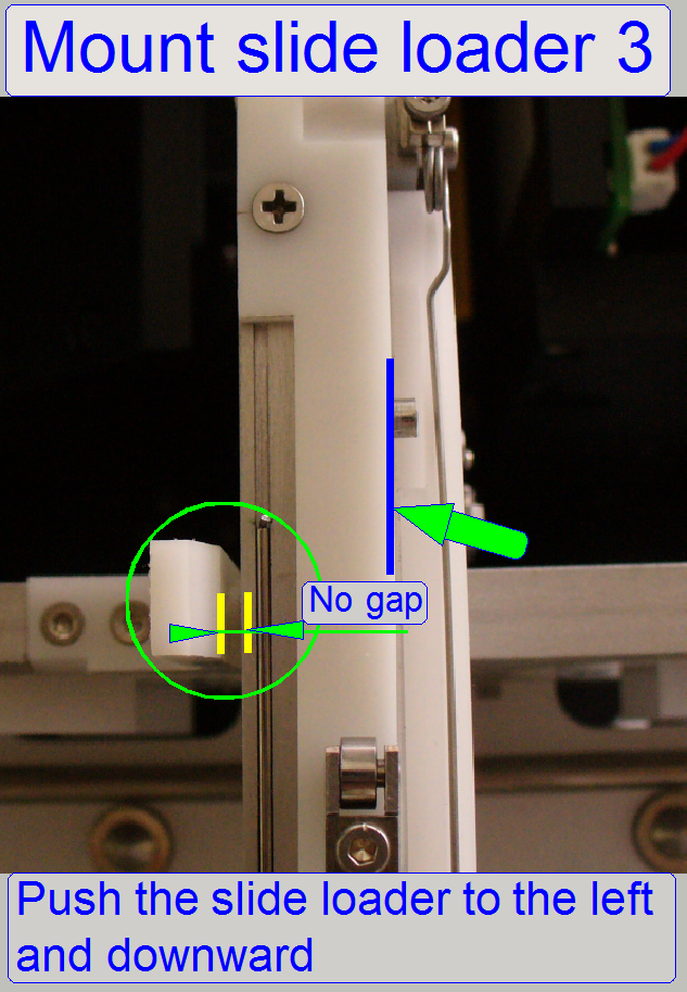
11. Push
the slide loader to the left and downward until the horizontal and vertical
position fixing of the “Inner slide loader mounting” is connected
alright; see “Mount the slide loader
· The slide
loader is connected well if the horizontal and vertical fixings on both sides
of the slide loader mounting are connected right and no significant gaps are
visible.
Move the slide loader moving part manually
For test purposes, the moving part of the slide loader
can be moved manually also. If the slide loader cable HMJ-1 is disconnected,
the movement is done easier.
The slide loader should be hold at the motor and / or
the clutch housing, but does not touch the sensor cover, it can be deformed
easily. The moveable part can be pulled on the mounting bolt of the inner
finger or pushed on the surface near to the inner finger or outer finger
mounting.
- To avoid deforming, other parts should not be touched for this purpose.
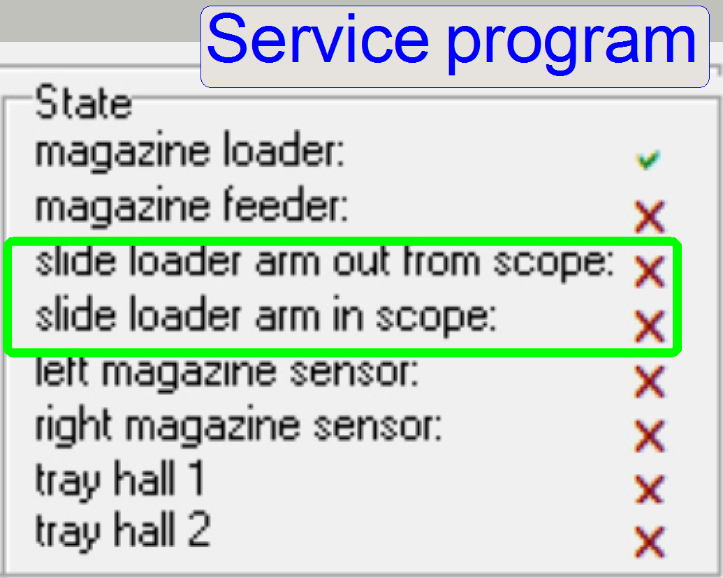
 Check the functionality of the slide loader sensors
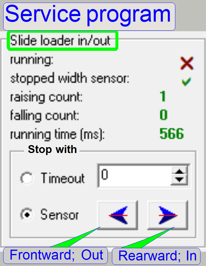
To check the inner sensor state, move the slide loader into the inner
end position by clicking the right hand arrow button of the “Slide loader in / out”
part of the service program. If the end position is reached, the sensor state
should be attached and stays attached, as signaled by the sensor state “slide
loader arm in the scope” (see below).
To check the outer sensor move
the slide loader moveable part backward by clicking the left hand arrow button
several times of the “Slide loader in / out” part of the service program.
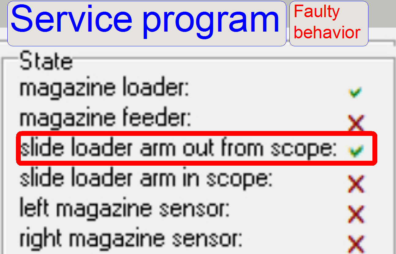
By pushing the slide loader moveable part backward manually
and then releasing it, the sensor state “Slide loader arm out from the scope”
should be attached and released either. Check this behavior several times.
- If the sensor stays attached after releasing it, faulty behavior
occurred and the SlideScanner.exe program will not finishing the start up
procedure.
Push the moving
part of the slide loader against the outer sensor operator manually. The sensor
state is shown with![]() ,
this means, the sensor is active.
,
this means, the sensor is active.
Now release the slide loader moving part, the spring
in the outer sensor operator should move the moving part to the outer limit
position and the sensor state have to be ![]() X.
X.
- If the sensor stays attached after releasing it, faulty behavior
occurred and the SlideScanner.exe program will not finishing the start up
procedure!
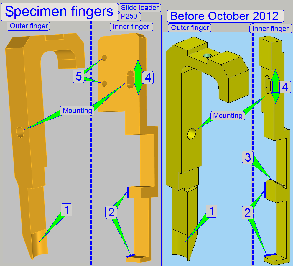
The shape (1) of the outer finger helps to positioning the slide into the middle of the outer finger (it should
be the middle of the magazine rail also) if the outer slide edge is attached
during slide insertion.
- During slide removal this part of the outer
finger has no function.
In case of slide insertion the inner finger does not touch the slide.
During slide removal the surfaces (2)
touches the upper and the lower part of the inner slide edge and shifting so
the slide back to the slide position of the magazine.
- During slide removal, and there was an empty
position in the magazine, the edge (3) must not collide with the slide
clamp.
Before
October 2012
The shape (1) of the outer finger helps
to positioning the slide into the middle of the outer finger (it should be the
middle of the magazine rail also) if the outer slide edge is attached during
slide insertion.
- During slide removal this part of the outer
finger has no function.
In case of slide insertion the inner
finger does not touch the slide, but it helps with the edge (3) to open the
slide clamp of the specimen holder (it lifts up the slide clamp). This way, the
slide insert procedure is done easier.
During slide removal the surfaces (2)
touches the upper and the lower part of the inner slide edge and shifting so
the slide back to the slide position of the magazine (in reality, the surfaces
are found on the opposite side).
- By adjusting the height of the inner slide
finger, the slide clamp of the specimen holder will be opened with the
edge (3) of the inner finger, even if the widest and thickest allowed
slide sizes are loaded.
- During slide removal, and there was an empty
position in the magazine, the edge (3) must not collide with the slide
clamp.
·
Since October 2012 the inner finger is
modified. In the new version, the slide clamp is not opened by the edge (3);
instead a separate slide clamp lifter is mounted to the mountings (5) of the
inner finger.
![]() “Slide clamp
lifter”; “Slide
loader and slide clamp”; “RemoveSlidePositionX2”
“Slide clamp
lifter”; “Slide
loader and slide clamp”; “RemoveSlidePositionX2”
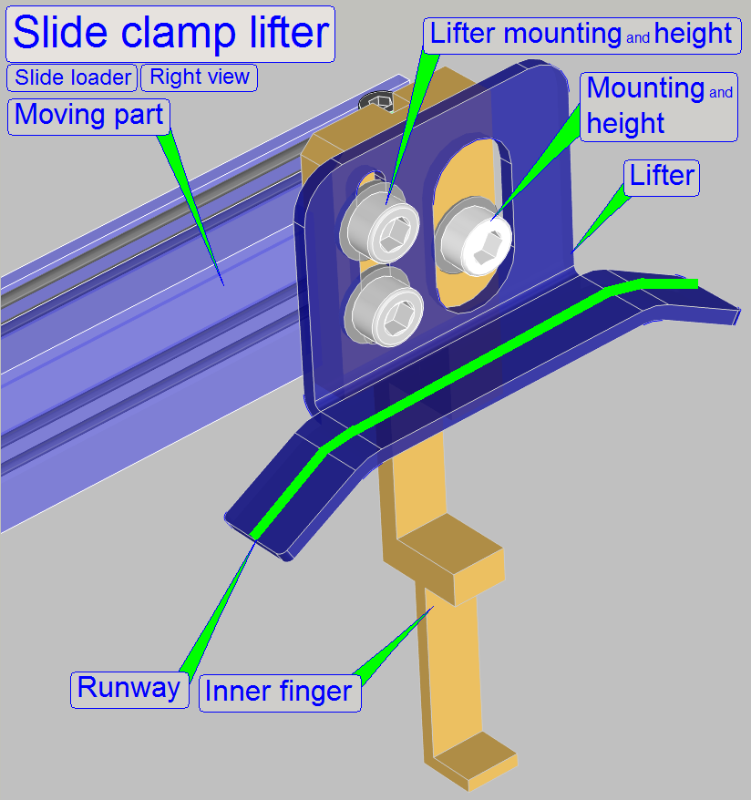 Scanners, delivered since October 2012, got a
slide clamp lifter to improve the slide clamp opening procedure. For this, the
slide clamp of the specimen holder is also modified; the lifter ball bearing
moves on the runway and opens so the slide clamp if the inner edge of the slide
will be inserted into the specimen holder.
Scanners, delivered since October 2012, got a
slide clamp lifter to improve the slide clamp opening procedure. For this, the
slide clamp of the specimen holder is also modified; the lifter ball bearing
moves on the runway and opens so the slide clamp if the inner edge of the slide
will be inserted into the specimen holder.
Scanners,
delivered before October 2012
The construction of the slide loader is modified since October 2012 and
increases the safeness of the movements.
Now, not the edge (3)
of the inner finger will open the slide clamp, instead a separate “Slide
clamp lifter” part is implemented and the construction
of the slide clamp is modified.
![]() “Adjust
the slide clamp lifter position”
“Adjust
the slide clamp lifter position”
Watch video: Slide clamp
lifter_P250
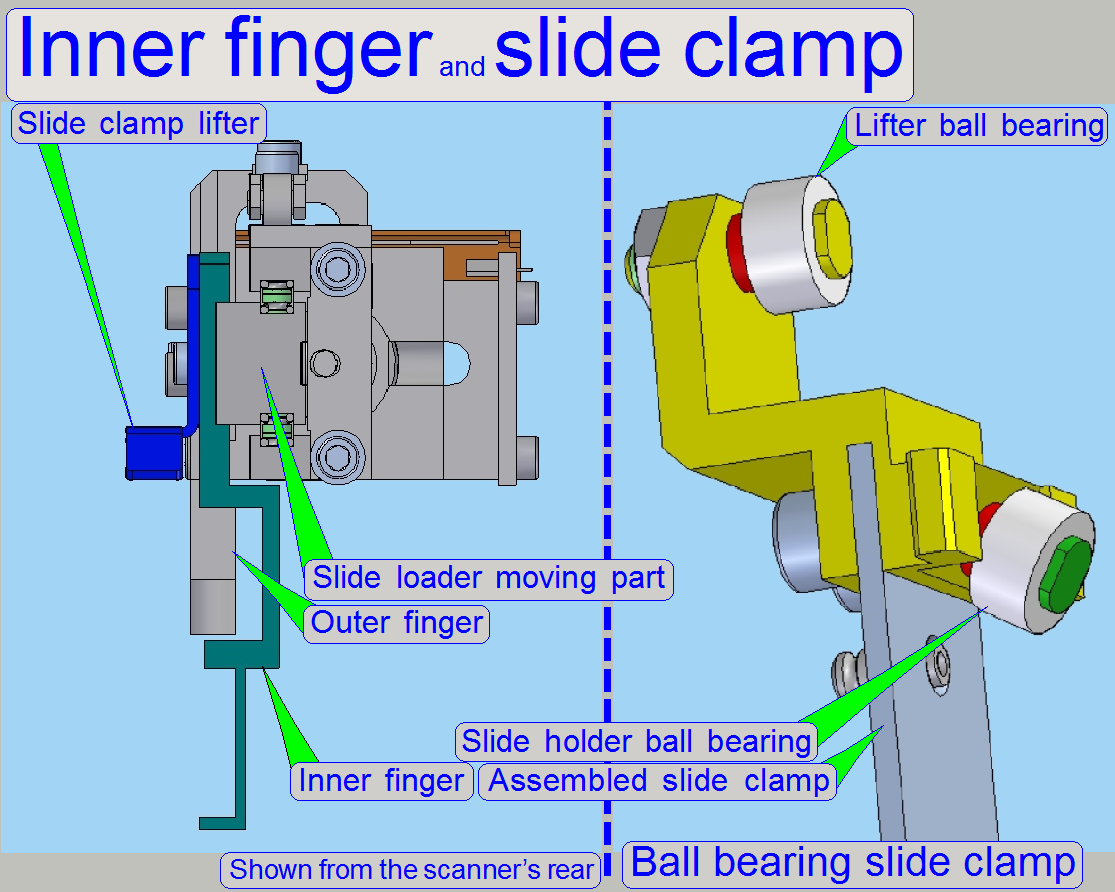
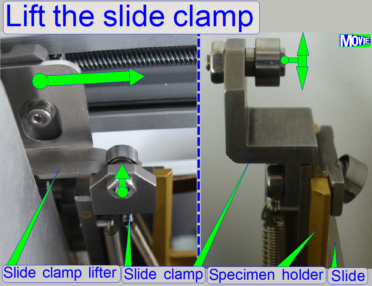
- The “Slide clamp lifter ball bearing” moves
on the runway of the “slide clamp lifter” with a very little mechanical
resistance and, as defined by the shape of the runway of the clamp lifter,
it lifts up the slide clamp until the first part (the inner edge) of the
slide is fully inserted.
- Then it lowers down the slide clamp again.
Remember, the slide may differ in length, width and thickness; see also: Slide
dimensions.
The leading of the slide from the magazine to the
specimen holder during the slide insert action requires special slide leading
means.
The successful slide insert operation depends on:
- The correct position
of the magazine unit; so the slide leading edge of the slide position
guide will be in plane with the right hand edge of the specimen holder;
the inner finger of the slide loader even passes the specimen holder’s
right hand edge.
- The correct height
of the slide loader’s inner finger or the height of the slide clamp lifter; so the slide clamp may be opened correctly to
insert the widest slides also.
- The correct position of the
specimen holder’s fixing fork; so the specimen holder does not move
sideward during the slide will be inserted; on the other hand, the
parallelogram limiter has not to be strained.
- The correct distance of the
slide leading spring to the slide leading edge (about 1.4mm); so the
slide will be moved to the slide leading edge and will be shifted on it.
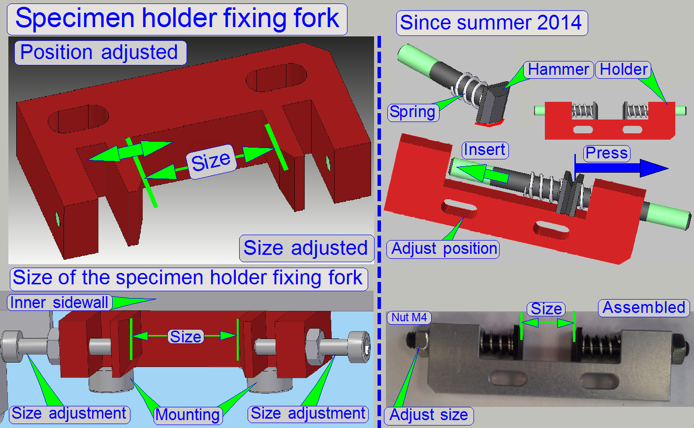 The specimen holder fixing fork is
mounted onto the inner magazine channel side wall from beneath by the use of
two bolts.
The specimen holder fixing fork is
mounted onto the inner magazine channel side wall from beneath by the use of
two bolts.
Because in the P250 the specimen holder has no contact
to the focus pin during slide insertion and slide removal, the specimen holder
position is fixed by this fork; see also “Adjust
the position of the specimen holder fixing fork”.
Position
adjustment
Check
/ adjust the magazine unit position first.
Adjust
the position of the fixing fork so, that the specimen holder is not pushed
in Z-direction (slide focusing) if the Y-stage moves the specimen holder into
the fork.
If the fork position is found, check the plane of the
slide leading edge and the specimen holder right hand edge again!
Since summer of the year
· During
insertion of the hammer into the holder, its not chamfered edge is near to the
holder.
· Do the
adjustment of the fixing fork’s size and its position as described above.
· Please
refer also to “Position
and size of the fixing fork”
The slide position guide defines with the slide
leading edge the horizontal position of the slide during slide insertion.
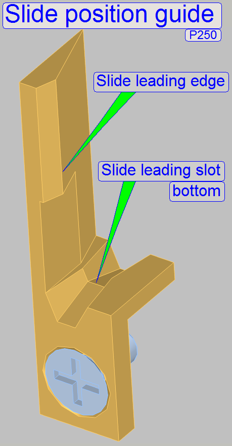 The slide leading slot bottom is
used to define the vertival position of the slide during slide insertion.
The slide leading slot bottom is
used to define the vertival position of the slide during slide insertion.
- During slide removal the parts have no function.
The slide leading
edge and slot is situated in the inner side wall of the
magazine channel. The slide “Leading Slot” bottom should be 0.1mm higher than
the lower edge of the specimen holder during slide insertion. The slide
“Leading edge” should be in the same plane with the specimen holder right hand
edge; see also ‘Adjust the
slide insert position in X-direction”.
The shape of the “Leading slot”, the construction of
the slide holding mechanics of the specimen holder (Slide clamp and lower edge)
and the width of the slide position in the magazine are together the reason for
the maximal allowed slide thickness of 1.20mm.
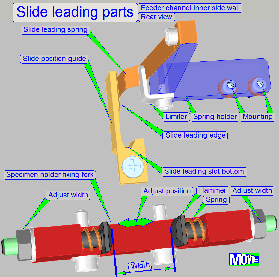
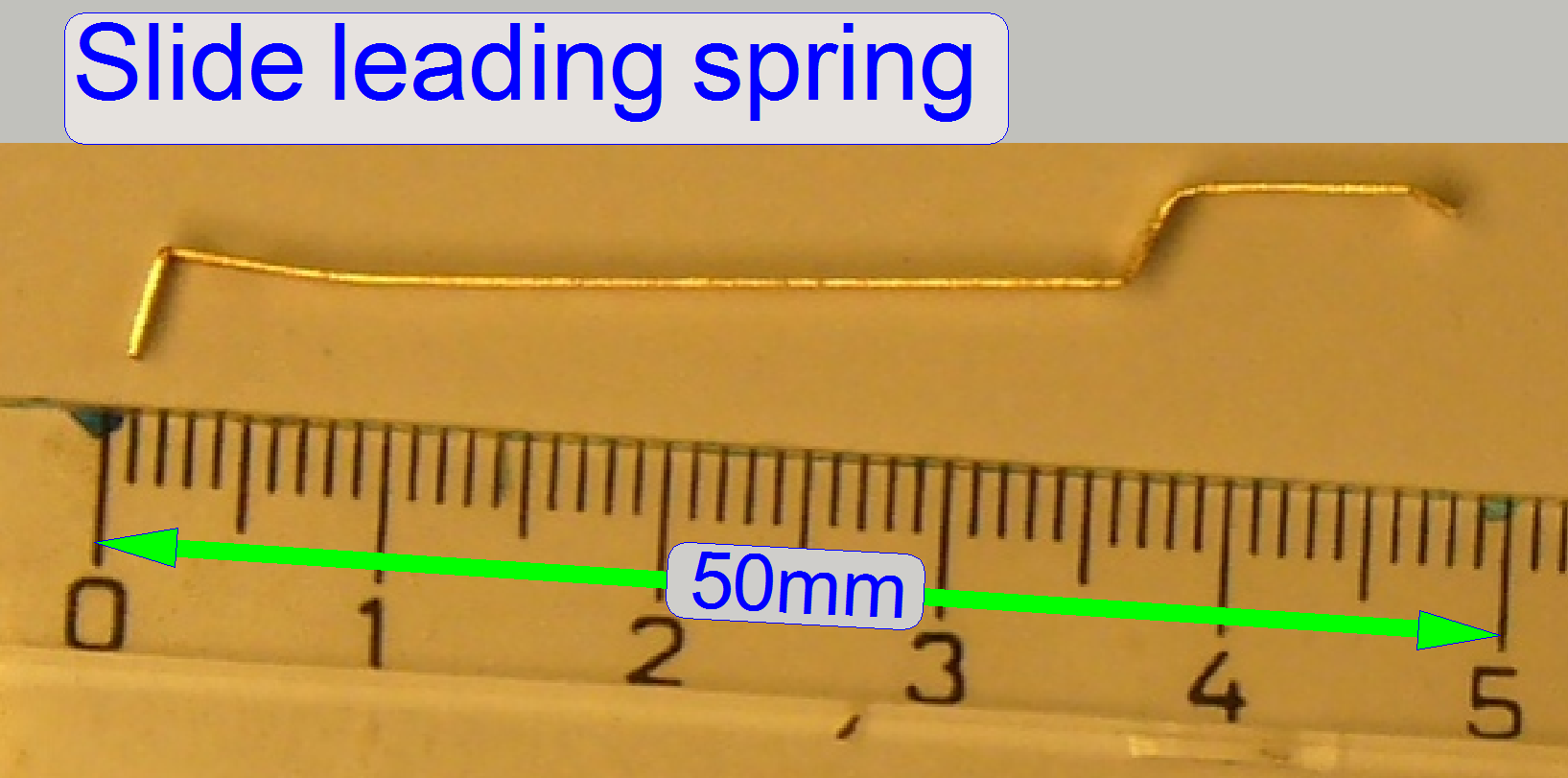
The
slide leading spring leads the slide to the slide leading edge of the slide
position guide and by shifting the slide along the leading edge, the horizontal
position of the slide is defined.
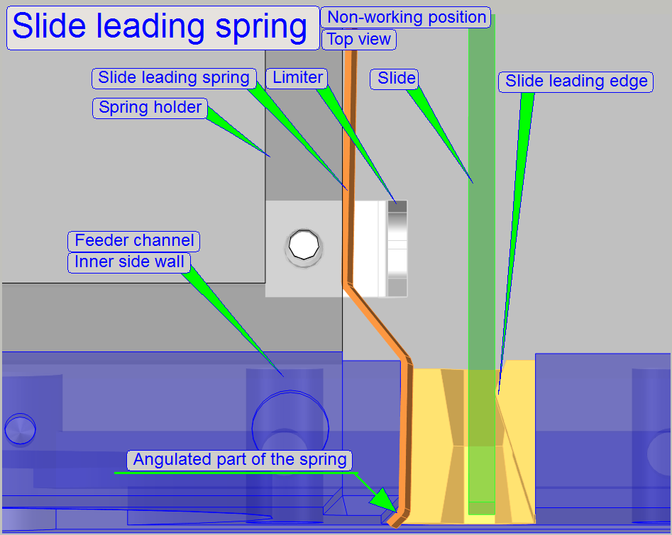
In
the non-working position, the angulated end of the slide leading spring must
not hit the inner side wall; only this way a deforming of the spring can be
avoided.
- The non-working
position is reached if the slide loader stays in the outer position.
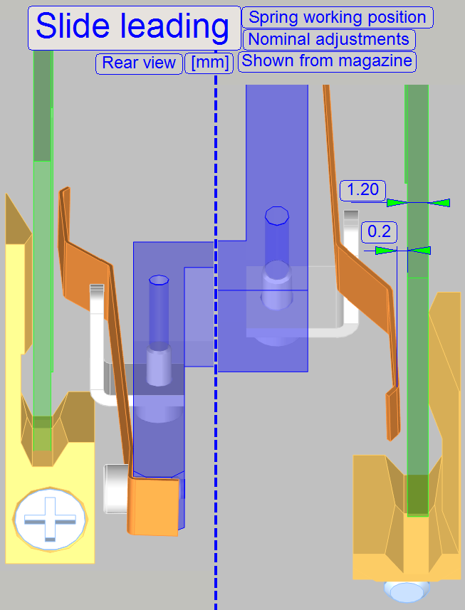
In
the working position, the distance of the spring to the slide leading edge
is important.
If we assume, that the maximal slide thickness is 1.20mm and the
thickness of the cover slip is 0.17mm, the resulting value together with tissue
will be 1.37mm, so about 1.40mm distance to the slide leading edge is required.
·
During slide insertion the slide leading spring must not
perform force against the cover slip.
The position of the slide leading spring is correct, if the distance to
the slide leading edge is:
1.37mm ≤ distance to the slide leading edge ≤ 1.45mm;
measured to the closest part of the spring.
Gap
to the slide
For this measurement, please use a slide with a thickness of 1.20mm
without cover slip.
0.2mm ≤ distance to the slide (without cover slip) ≤ 0.30mm;
measured to the closest part of the spring.
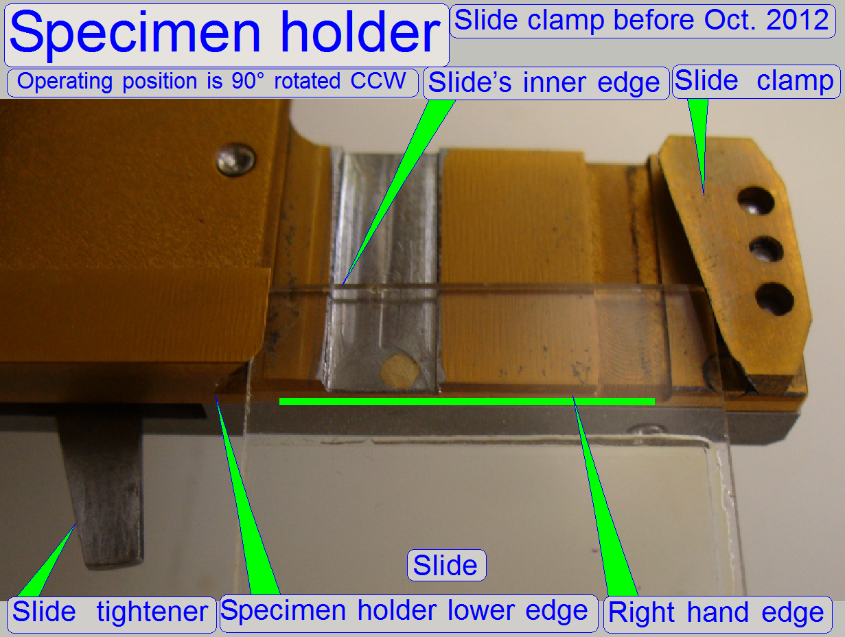
The slide clamp of the
specimen holder, together with its lower edge holds the slide during scan
operation or moving the specimen holder inside the scan area. If the slide
insert or removal position is reached, the slide clamp is loosened via the
slide tightener; only the small force of the “Soft Spring” situated behind the
slide clamp will hold the slide clamp and the slide can be moved easily.
If the slide insert or removal position will be
reached, the Slide tightener touches
the magazine feeder channel from below meanwhile the specimen holder moves in
upward direction and forces so the “Strong spring”, situated behind the slide
clamp to release the slide clamp (details about the
specimen holder mechanics are discussed in the file “The X-Y-stage”).
- During slide insert operations, the right hand edge of the specimen
holder has to be in the same plane as the
slide leading edge.
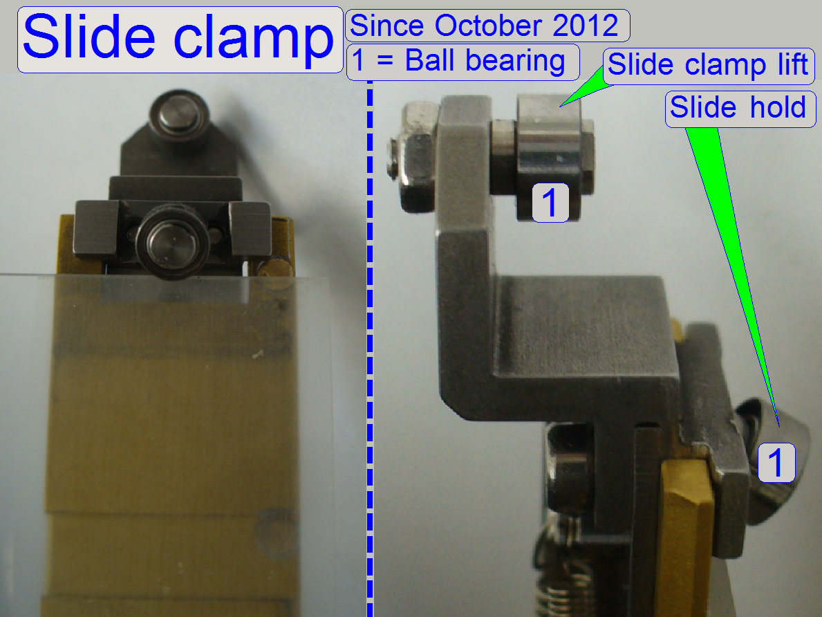
The following steps describe the slide insert and
removal procedure as it is done by software.
1.
The focus pin goes to the position -300
steps to move the specimen holder away from the objective; this position has no
reason in question of the slide load procedure.
2.
The specimen holder goes to the slide
insert position in X-direction (InsertSlidePositionX)
and Y-direction (InsertSlidePositionY1).
In this position the slide “Leading edge” of the slide position guide should be
in the same plane with the “Right hand edge” of the specimen holder; the
specimen holder position is fixed by the fixing fork.
3.
Meanwhile the specimen holder moves upward
(-X direction), the slide tightener will be moved to “The
specimen holder fixing fork” and releases so the slide clamp; it will be
hold only by the force of the soft spring. The slide can be moved now easy into
the specimen holder.
4.
If the slide insert position is reached (InsertSlidePositionX),
the slide loader motor is started with a time of 600ms. The outer finger touches
the slide edge and moves the slide in direction to the specimen holder;
meanwhile the shape of the outer finger helps to find the middle of the
rail.
5.
A few 100 ms later, the slide leading
spring pushes the slide in direction of the slide leading edge.
6.
The “Slide leading
slot” leads the slide lower part to the specimen holder “Lower edge” and
the “Leading edge” defines the position of the slide in relation to the “Right
hand edge” of the specimen holder.
7.
If the inner finger arrives to the slide
clamp of the specimen holder, the edge (3) of the inner finger (or the slide
clamp lifter, depending on the hardware version) opens the slide clamp and
helps to insert the inner edge of the slide easily, the first part of the slide
is inserted.
8.
If the time of 600ms is over, the specimen
holder moves to the final Y-position (InsertSlidePositionY2,3).
Both parameters have always the same value.
9.
The slide loader motor is started again
until the inner sensor of the slide loader is attached. The software will
switch off the motor and the inner sensor stays attached; the slide is
inserted.
10. Now
the specimen holder moves with the slide in +X direction (downward) with the
value of the parameter “DeafultPositionX”;
nearly to the limit “Xmax”.
11. The
slide loader motor is started again, but now in opposite direction until the
slide loader outer sensor is attached and the slide loader motor will be
switched off by software. A spring moves now the slide loader moveable part to
the outer position fixing, meanwhile the outer sensor will be released; the
software checks the released state of the sensor after 300 ms
(SlideLoaderDelayTimeBeforeSensor) and the slide insert procedure is finished
or, if the sensor is not released or the sensor was not attached and the time
was run out, the message “Slide loader arm got stuck during process” will be
issued.
12. The
focus pin goes to the position -300 steps to bring the specimen holder into the
nominal slide removal position horizontally (Z-direction).
13. The
specimen holder goes to the positions Y-Home1,2 and X-Home1,2.
14. To
remove a slide, the specimen holder moves first with the slide in +X direction
(downward) with the value of the parameter DeafultPositionX nearly to the limit
Xmax. The correct Y-remove position is defined with the value of the parameter
RemoveSlidePositionY.
15. The
software will switch on the Slide Loader motor until the inner sensor will be
attached.
16. Now
the specimen holder goes in –X direction (upward) and moves so the slide
between the inner and outer finger of the slide loader. The end position is
defined by the value of the parameter “RemoveSlidePositionX1”.
17. Meanwhile
the specimen holder moves upward (-X direction), the slide tightener will be
moved to the lower edge of the specimen holder fixing fork and releases so the
slide clamp; the slide will be hold by the force of the soft spring only.
18. The
Slide Loader motor is switched on in backward direction for 300ms and then
stops the movement; the surfaces
(2) of the inner finger touches the slide inner edge and moves so the
slide backward; the outer part of the slide stays over the magazine rail. The
inner finger stays inside the specimen holder before the slide clamp.
19. Now
the specimen holder goes to the position, defined by the value of the parameter
“RemoveSlidePositionX2”. This value is so defined, that the slide loader’s inner finger edge
(3) can cross the slide clamp, if no slide is present in the specimen
holder but the software executes a slide removal action. If the slide clamp
lifter is used to open the slide clamp, it should also be able to move backward
without jamming if no slide is present in the specimen holder.
20. The
slide loader motor is switched on again in backward direction; the slide will
be moved into the rail of the slide position of the magazine. If the slide
loader’s outer sensor is attached; the slide loader motor will be switched off
by the software. At the end of this procedure a spring moves now the slide
loader moveable part to the outer position fixing, meanwhile the outer sensor
will be released and the software checks the released state of the sensor after
300ms (SlideLoaderDelayTimeBeforeSensor). The slide removal procedure is
finished.
21. With
the magazine feeder, the next or any slide position in the magazine can be
found to select the slide to be inserted next.
Watch video: Magazine load_P250
Magazine unload_P250
Slide insert test_P250
Slide clamp lifter_P250
Full
adjustment of the magazine unit
The following procedures and
checks are done to adjust all the components of the magazine unit; the result
should be:
- The slides with the specified slide dimensions should be inserted easily into the specimen holder, without any
slide insert difficulties.
- The slides with the specified slide
dimensions should be hold in the specimen holder correctly, the slide must
not change its position during slide scanning.
- The slides with the specified slide
dimensions should be removed easily from the specimen holder and placed
return into the slide position of the magazine, without any slide removal
difficulties.
- The magazines should be loaded from the
input stack into the magazine channel without stumble or magazine jamming.
- The magazine should move in the magazine
channel easily; without magazine jamming.
- The magazine should be moved from the
magazine channel into the output stack correctly, without magazine
jamming.
- The magazine input stack sensor should
show the state “Magazine present”.
- The magazine output stack sensor should
show the stat “Magazine output stack full”.
- The magazine supporters should work
correctly.
Checks
Before you are starting any
scanner checks or adjustments, please check the following conditions:
The magazine
The slide positions are
clean and dry (no cover slip glue residues, no dust and no glass shards can be
found); otherwise clean the slide positions of the magazine.
- The magazine, used for the check and
adjustment purposes should be cleaned by the use of a brush and compressed
air or canned aerosol cleaner.
The permanent magnet is
present and works correctly together with the input and output magazine stack sensor (check this behavior with the service program).
The magazine input sensor
and the magazine output sensor are switching correctly! Check this behavior
with an empty magazine and the service program!
The slide
The used slide(s) (of the
user) fulfill the allowed slide dimensions.
The cover slip should not be
less than 1.0mm from the slide edge; it should be in distance from the slide
holding mechanics of the specimen holder.
Labels or stickers should be
found only on the barcode area, beside the cover slip.
- Please
make a security backup of the file “Microscope
Configuration.ini”!
The following sequence is
based on the adjustments of the new components (since October, 2012; the
specimen holder fixing fork, the slide leading spring and the slide clamp
lifter mechanics), but by replacing the appropriate procedure, the other,
earlier developed components can be adjusted as well by the use of this
sequence.
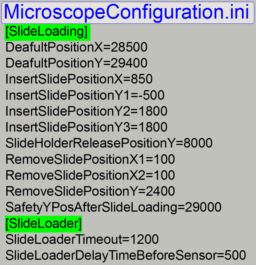 For
checks, use the appropriate values in the relevant section of the file “MicroscopeConfiguration.ini”
of the scanner in question!
For
checks, use the appropriate values in the relevant section of the file “MicroscopeConfiguration.ini”
of the scanner in question!
1) Check / adjust the magazine load mechanics
2) Check / define the hardware limits of the X-Y-stage unit.
3) Check / adjust the magazine unit position.
4) Check / adjust the position and the size of the specimen holder fixing
fork.
5) Check / adjust the magazine position for the slide insert / removal
operation.
6) Check the magazine load / unload operation.
7) Check
/ define the value of the parameter “DefaultPositionX”.
8) Check / define the slide insert position in X-direction; define
“SlideInsertPositionX”.
9) Check / adjust the position and the height of the inner finger.
10) Set the slide
insert start position in Y-direction; define “InsertSlidePositionY1”
11) Check / define the final slide insert position in Y-direction.
12) Check / adjust the height and the position of the slide clamp lifter.
13) Check / define the slide removal position in Y-direction.
14) Check / define the slide removal position “X1” in X-direction.
15) Check / define the slide removal position “X2” in X-direction.
- Run the tests to check the magazine
load / unload and the slide insert / removal procedures
Check or
define the hardware limits of the X-Y-stage unit
Important
For the following checks, use the values in
the section [HardwareLimits] of the file “Microscope
Configuration.ini” of the scanner in question; the here shown example values must not to be used!
Requirements:
- During movements of the specimen holder in X-Y-direction lost steps
(not more than +-2 steps) have not to be experienced.
Check the
hardware limits in X-direction
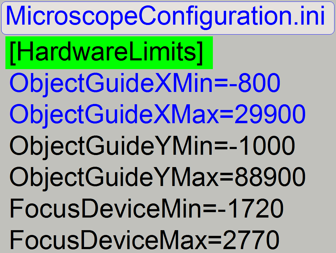 Check the negative limit in -X-direction
1.
With the service program set the Y-carriage to
Home1,2.
2.
Set the X-carriage to Home1,2.
3.
With the service program go forward in direction of
the negative limit to the X-motor position, defined as value of the parameter
“ObjectGuideXMin”; in the example on the right it would be 700 steps.
4.
Go backward 700 steps.
5.
Press Home1 (only). There should be not more than +-2
steps difference to Home1. If there are more steps lost, the negative limit is
faulty, define / find the negative limit.
6.
If there are not more than 2 steps difference to
Home1, increase the number of steps by 100 steps.
7.
With the new value (now 800 steps, in relation to the
example) go in direction to the negative limit.
8.
 Go backward 800 steps in
direction to Home1.
Go backward 800 steps in
direction to Home1.
9.
Press Home1 (only).
10.
If there are more than +-2 steps lost, the limit
position is found correctly; the appropriate limit must not be defined again.
Check
the positive limit in +X-direction
11.
With the service program set the Y-carriage to
Home1,2.
12.
Set the X-carriage to Home1,2.
13.
With the service program go forward to the X-motor
position, defined as value of the parameter “ObjectGuideXMax” in the example on
the right =30100 steps.
14.
Go backward 30100 steps.
15.
Press Home1 (only). There should be not more than +-2
steps difference to Home1. If there are more steps lost, the positive limit is
faulty, define / find the positive limit.
16.
If there are not more than 2 steps difference to
Home1, increase the number of steps by 100 steps.
17.
With the new value (now 30200 steps, in relation to
the example) go in direction to the positive limit.
18.
Go backward 30200 steps in direction to Home1.
19.
Press Home1 (only).
20.
If there are more than +-2 steps lost, the limit
position is found correctly; the appropriate limit must not be defined again.
![]() Find the hardware limits of the X-carriage
Find the hardware limits of the X-carriage
Check the hardware limits in
Y-direction
·
Insert a slide into the
specimen holder manually
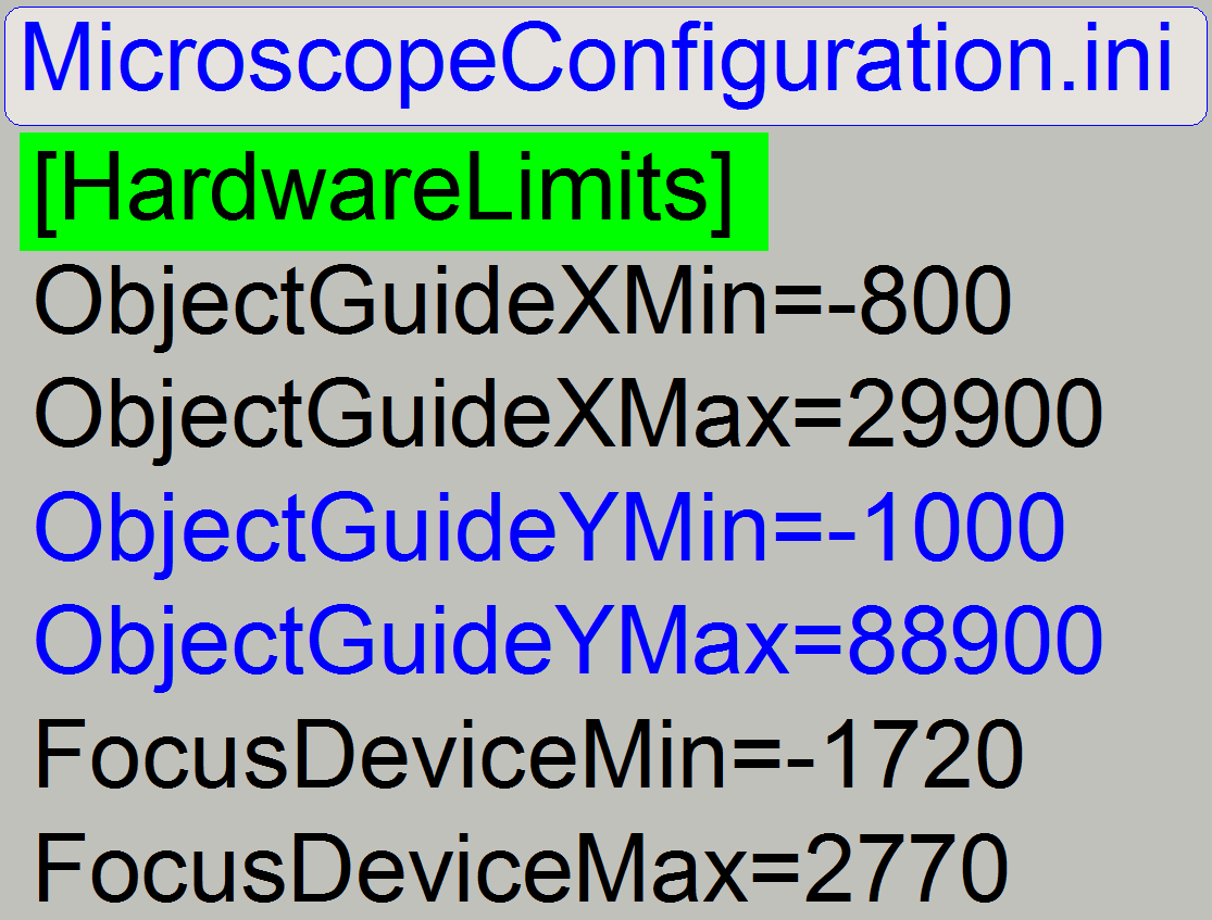 Check the negative limit
in -Y-direction
Check the negative limit
in -Y-direction
21.
With the service program set the Y-carriage to
Home1,2.
22.
Set the X-carriage to Home1,2.
23.
Go forward to the position X=28000 steps.
24.
With the service program go forward to the Y-motor
position, defined as value of the parameter “ObjectGuideYMin” in the example on
the right =-1200 steps.
25.
Go backward +1200 steps.
26.
Press Home1 (only). There should be not more than +-2
steps difference to Home1. If there are more steps lost, the negative limit is
faulty, define / find the
negative limit.
27.
If there are not more than 2 steps difference to
Home1, increase the number of steps by 100 steps.
28.
With the new value (now 1300 steps, in relation to the
example) go in direction to the negative limit.
29.
 Go backward +800 steps in
direction to Home1.
Go backward +800 steps in
direction to Home1.
30.
Press Home1 (only).
31.
If there are more than +-2 steps lost, the limit
position is found correctly; the appropriate limit must not be defined again.
Check
the positive limit in +Y-direction
32.
With the service program set the Y-carriage to
Home1,2.
33.
Set the X-carriage to Home1,2.
34.
Go forward to the position X=29000 steps.
35.
With the service program go forward to the Y-motor
position, defined as value of the parameter “ObjectGuideYMax” in the example on
the right =90100 steps.
36.
Go backward 30100 steps.
37.
Press Home1 (only). There should be not more than +-2
steps difference to Home1 and the focus pin should not touch the specimen
holder! If there are more steps lost, the positive limit is faulty, define / find the positive
limit.
38.
If there are not more than 2 steps difference to
Home1, increase the number of steps by 100 steps.
39.
With the new value (now 30200 steps, in relation to
the example) go in direction to the positive limit.
40.
Go backward 30200 steps in direction to Home1.
41.
Press Home1 (only).
42.
If there are more than +-2 steps lost, the limit
position is found correctly; the appropriate limit must not be defined again.
Execute the procedure “Find the hardware limits” if necessary.
Check the magazine unit position
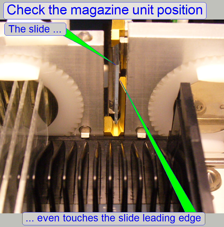
Requirement
·
If the slide is
pushed from the specimen holder in direction to the slide leading edge
(manually), the slide leading edge should be even touched by the slide.
·
If the slide
leading edge will be hit or a gap exists between slide and slide leading edge,
adjustments are required.
- Insert a slide manually into the
specimen holder.
1. Set the specimen holder to the positions Y-Home1,2
and X-Home1,2.
2. Shift the slide carefully backward (the specimen holder
has not to be moved in Z-direction), in direction to the magazine. The slide
should be a little bit higher than the slide leading slot bottom. If required,
move the X-stage some hundred steps in direction to the negative limit, “ObjectGuideXMin”.
3. If the slide leading edge is not touched or the
slide will hit the slide leading edge:
a. The position of the magazine unit may be wrong and /
or
b. The position of the “Specimen holder fixing fork” is
wrong.
4. Shift the slide return into the specimen holder so,
that a movement in the +X-direction can be performed.
5. Move the X-stage 28000 steps in plus (+) direction.
6. Loosen the “Specimen holder fixing fork” from
beneath until it becomes easily moveable.
7. Move the X-stage 28000 return to the previous
position. With this movement, the specimen holder fixing fork may move in
Z-direction as required; it will not fix the specimen holder in the wrong
position.
8. Now shift the slide again in direction to the slide
leading edge and check the behavior:
9. If the slide leading edge is not touched or the
slide will hit the slide leading edge:
10. The position of the magazine unit is wrong.
- Adjust the position of the magazine unit first
- Adjust the position of “The specimen holder fixing fork” next.
Adjust the magazine
unit position
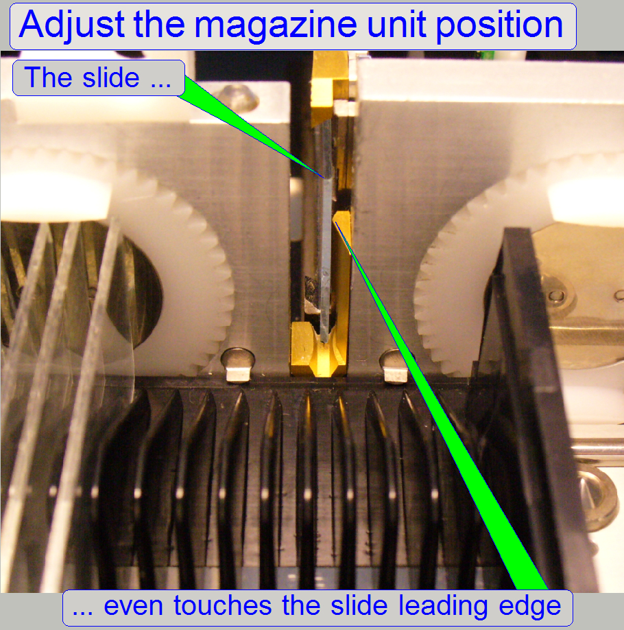 Task
Task
·
Adjust the
position of the magazine unit so, that the slide leading edge is even touched
by the slide if the slide is pushed from the specimen holder in direction to
the slide leading edge (manually).
·
If the slide
leading edge will be hit or a gap exists between slide and slide leading edge,
adjustments are required.
![]() “Magazine unit mounting” and “Magazine unit position adjustment”
“Magazine unit mounting” and “Magazine unit position adjustment”
11. Set the specimen holder to the positions Y-Home1,2
and X-Home1,2.
12. Insert
a slide manually into the
specimen holder.
13. The slide should be a little bit higher than the
slide leading slot bottom. If required, move the X-stage in direction to the
negative limit, “ObjectGuideXMin”.
14. Move the X-stage 28000 steps in plus (+) direction.
15. Loosen the “Specimen holder fixing fork” until it
becomes easily moveable.
16. Move the X-stage 28000 steps return to the previous
position. With this movement, the specimen holder fixing fork may move in
Z-direction as required; it will not fix the specimen holder in the wrong
position.
17. Shift the slide carefully backward, in direction to
the slide leading slot; the specimen holder should not move in Z-direction;
otherwise repeat from step 13 logically.
18. If the slide leading edge is not touched or the
slide will hit the slide leading edge:
a. Loosen the magazine unit fixing bolts a little bit
until the magazine unit may be barely shifted on its mounting and
b. Drive the magazine unit position adjustment bolts as required.
19. Shift the slide return into the specimen holder so,
that a movement in the +X-direction can be performed.
20. Move the X-stage 28000 steps in plus (+) direction.
21. Move the X-stage 28000 return to the previous
position. With this movement, the specimen holder fixing fork may move in
Z-direction as required; it will not fix the specimen holder in the wrong
position.
22. Now shift the slide again in direction to the slide
leading edge and check the behavior:
23. If the slide leading edge is not touched or the
slide will hit the slide leading edge, repeat from step 18b.
24. If the slide even touches the slide leading edge
tighten the magazine unit fixing bolts and check the behavior again; repeat
from step 19 one time.
- If the position of the magazine unit is
correct, adjust “The position of the specimen holder fixing fork” next.
Position and the size of the
specimen holder fixing fork
Task
- Adjust the position of the
fixing fork so, that the specimen holder is not pushed in Z-direction if
the Y-stage moves the specimen holder into the fork.
- Adjust the size of the fork so, that
movement in Z-direction of the specimen holder is not possible but the
specimen holder moves easily in the fork it should not be pressed by the
fork.
Adjust the size of the specimen
holder fixing fork
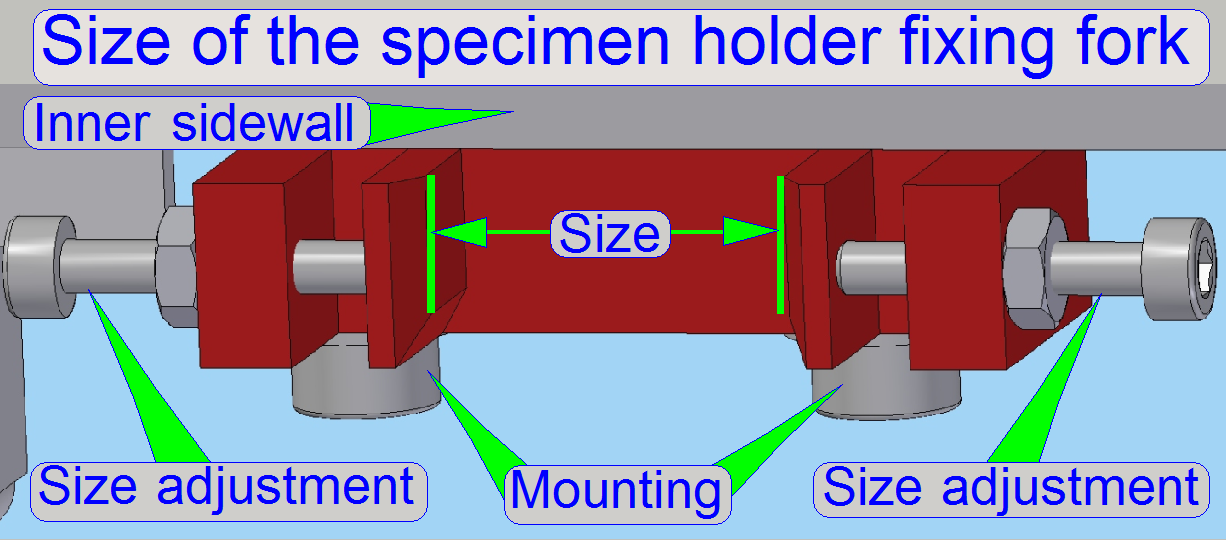
The size of the specimen
holder fixing fork can be adjusted in a small range by driving the size
adjustment bolts.
The adjustment is correct,
if:
- The specimen holder can not move in
Z-direction (focusing direction) during the slide insertion or removal
procedure and
- The specimen holder does not move strong;
it is not be pressed by the fork.
Adjust the position of the specimen holder
fixing fork
 Task
Task
- Find the correct position of the specimen holder fixing fork so,
that the specimen holder right hand edge is in plane with the slide
leading edge and the parallelogram is not moved in Z-direction.
- This adjustment assumes that the magazine
unit position is already adjusted correctly.
1.
Move the Y- and X-stage to the positions
Home1,2.
2.
Move the X-stage to the position 28000
steps.
3.
Move the Y-stage to the position 88000
steps.
4.
Loosen the mounting bolts of the fixing
fork from beneath.
5.
Move the Y-stage until the position Y=3200
steps is reached.
6.
Move the Y-stage backward in direction to
Home1,2 by 100 steps until the movement surface will touch the fixing fork.
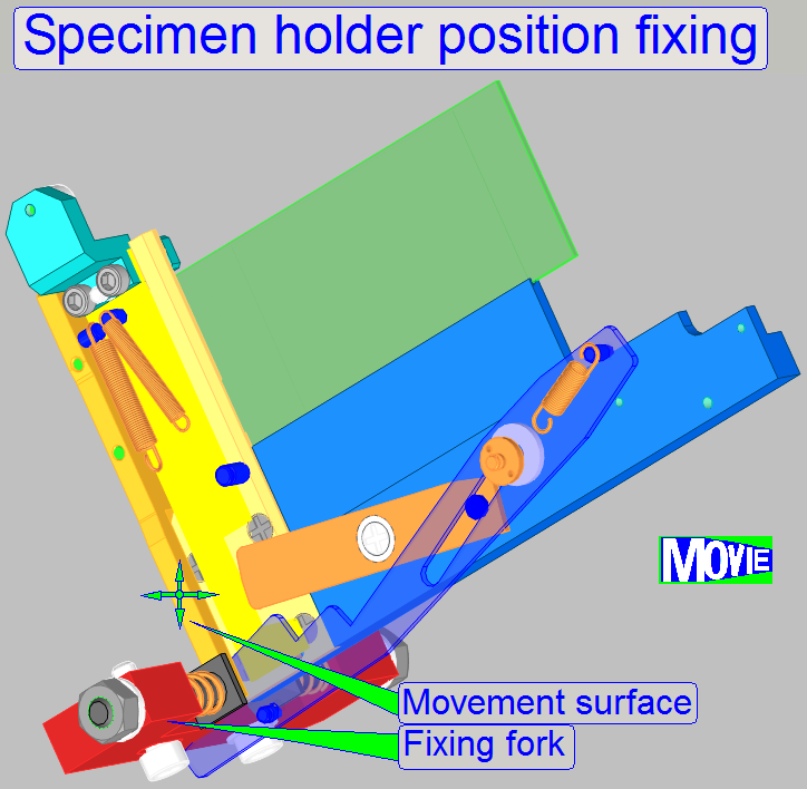
7.
Fit the fixing
fork with the movement surface of the specimen holder and tighten the mounting
bolts of the fixing fork; please do not touch the specimen holder during this
action, it should not move in Z-direction!
8.
Check the adjustment by repeating this
sequence from the step 5. If the specimen holder movement surface touches the
fixing fork, no movements in Z-direction should be experienced,
otherwise repeat from step 3.
·
If the correct position of the fork is
found, check the plane of the slide leading
edge and the specimen holder right
hand edge again; execute the steps logically as described in: check the magazine
unit position!
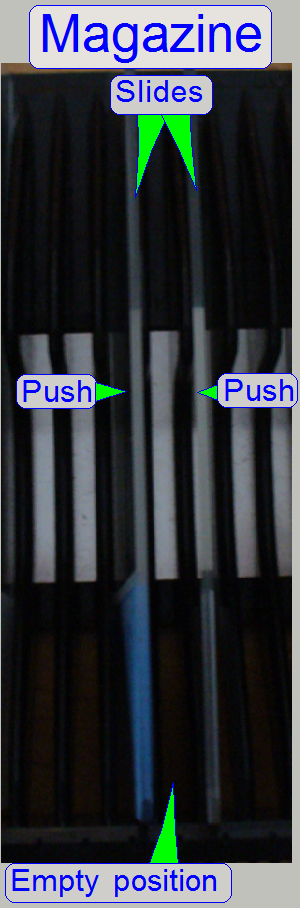
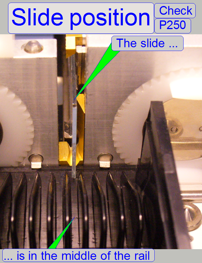 Task
Task
- Adjust the slide position of the magazine
so, that the outer specimen finger is in the middle of the slide slot of
the magazine.
- The adjustment is done by positioning the
“The
magnet disc” on the feeder
spindle.
The adjustment assumes, that
the position of the magazine unit and the position of the specimen holder fixing fork is correct.
1.
Insert a magazine
manually or by the use of the service program, prepared with
two slides, nearly in the middle of the magazine as shown on the right
(“Magazine”).
3.
With the part “magazine feeder” of the
service program move the magazine in the feeder channel until the slide loader
stays over the “empty position”, between the two slides, and the stop position of the
magnet disc is “Stop forward”, the slide insert position.
4.
Move the slide loader moving part manually
a little bit into the scanner until the outer finger can be seen easily.
5.
Push the two slides toward the outer
finger.
6.
If the gaps on both sides of the outer
finger are not equal, memorize the “Stop forward” position then rotate the
magnet disc until the gaps are equal. Memorize this position also.
7.
Loosen the magnet disc fixing and rotate
the magnet disc by the difference of the two memorized positions and tighten
the fixing bolt.
8.
With the service program move the slide
loader moving part into its outer end position, rotate the feeder gear backward
two turns, then rotate the feeder gear forward until the empty position of the
magazine is found again, the stop position of the magnet disc is “Stop
forward”.
9.
Repeat from step 4 until the gaps are
equal on both sides.
If the adjustment is finished, check the correctness
of the found position by executing the magazine load test. Check all the
magazines without any slide in any magazine.
![]() “Check the magazine
load procedure”.
“Check the magazine
load procedure”.
Check the magazine load
and unload procedure
The
result should be
- All the empty magazines, used with this scanner can be loaded from the
input stack into the magazine feeder channel without stumble; insert the
magazines into the input stack one by one!
- If not: Check the
rack of the magazine in question.
- If more magazines failed this test, adjust the
slide insert position of the magazine more precise.
- If more magazines failed this test, check the
smoothness of the side wall surface in relation to the stack wheels;
the stack wheels should be about 0.1mm deeper as the surface of the
side wall.
- The magazine (all 10 magazines), arrived onto the feeder rails,
should be recognized by the left magazine sensor and should be moved to
the first slide position.
- Now check the first slide position visually, it should fit with the
slide leading slot.
- By moving the magazine to the magazine unload position, the unload
position should be found correctly and the magazine should be moved into
the output stack evenly and smoothly, without stumble.
- Check the correct function of “The magazine
supporters” also.
- If 9 magazines are present in the output stack and the 10th
magazine will be moved into the output stack, the test program should send
a message, that the output stack is full.
Check this behavior with the options “Magazine load”
and “Magazine unload” of the service part of
the program “SlideScanner.exe”.
If the magazine load / unload test with the empty
magazines is finished, prepare some magazines as follows:
- Fill the left side of a magazine with 10 slides.
- Fill the right side of a magazine with 10 slides.
- Fill an entire magazine with slides (25 slides).
Check the smoothness and the correctness of the
magazine load procedure (without stumble) with the options “Magazine load” and
“Magazine unload” of the service part of
the program “SlideScanner.exe”.
Define the value of the parameter “DeafultPositionX”
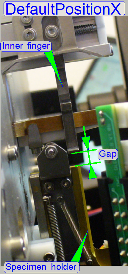 Task
Task
· This
value allows the movement of the inner finger above the slide clamp and the specimen
holder if a slide was inserted and the slide loader moves backward without
slide after a slide insert procedure or
· The
slide loader moves inward, into the scanner, before the real slide removal
procedure will be executed.
· In
both movements of the slide loader, the inner finger has not to hit the
specimen holder or the slide clamp.
· Check
the value by inserting and removal of the widest and thickest test slide
manually (26.1mm wide and 1.20mm in thickness).
Requirements
·
The hardware limit in the direction “Xmax”
has to be defined correctly.
DeafultPositionX
= ObjectGuideXMax - 100 steps.
Example
If the hardware
limit in +X-direction is found with “ObjectGuideXMax” = 29800 steps, the value
of the parameter “DeafultPositionX” will be 29700 steps.
- Update the value of the parameter “DeafultPositionX” in the section
[SlideLoading] of the file “Microscope Configuration.ini” and save the
file.
Remark
The value of the parameter “DeafultPositionX” is not
critical, but a gap between “Slide loader inner finger” and the slide clamp and
specimen holder has to exist, if specified movements are executed.
Adjust the slide insert position in X-direction
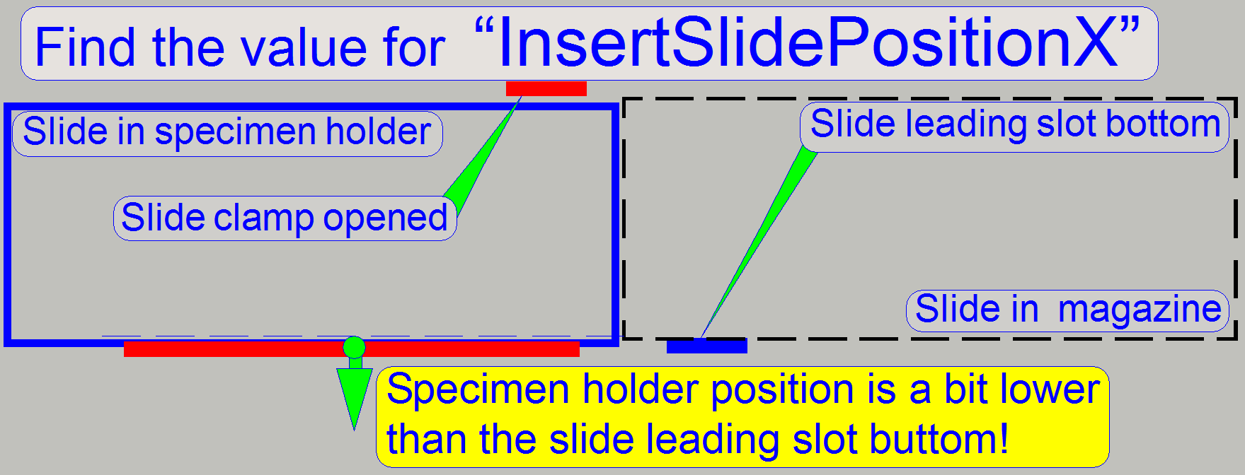
Task
- Define the value for the parameter “InsertSlidePositionX” so, that
the slide lower edge does not collide with the lower edge of the specimen
holder during slide insertion.
- The widest and thickest allowed slide has to be inserted smoothly
also.
To reach this, the “Level height” has to be found
first.
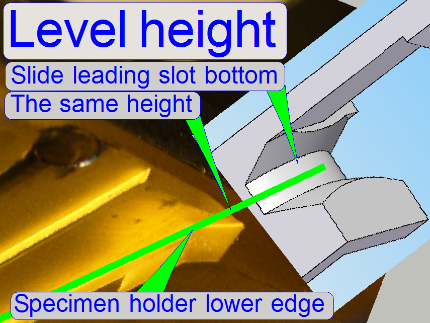 The “Level height” means the
position of the specimen holder in motor steps of the X-direction where the
specimen holder lower edge is in the same height as the bottom of the slide
leading slot.
The “Level height” means the
position of the specimen holder in motor steps of the X-direction where the
specimen holder lower edge is in the same height as the bottom of the slide
leading slot.
·
Please notify the found value of the
“Level height”, it will be required again if the value of the parameter “RemoveSlidePositionX1” will be
defined.
InsertSlidePositionX = level height +600 steps ±100 steps
Because we are defining the level height in an
accuracy of 100 steps, the tolerance of +-100 steps may occur.
1.
Set the positions Y-Home1,2 and X-Home1,2
of the X-Y-Stage.
2.
Set the focus position to -300 steps.
3.
Set the Y-direction to the value of the
parameter InsertSlidePositionY1.
4.
Remove the slide loader and put a utility
knife blade onto the lower edge of the specimen holder.
5.
Move the blade in direction to the slide
leading slot bottom.
6.
If the blade hits the slide leading slot
bottom, move the X-stage in direction to the negative limit by 100 steps and
check the height again with the blade.
7.
Repeat the previous step until the
specimen holder is in the same height as the slide leading slot bottom.
8.
If the correct “Level height” is found,
add to the actual number of steps in X-direction 600steps.
“SlideInsertPositionX”
= Level height + 600 steps.
Example: If the found Level height is -500 steps (shown by the
service program, X-direction step number), the value of the parameter
“SlideInsertPositionX” will be +100 steps.
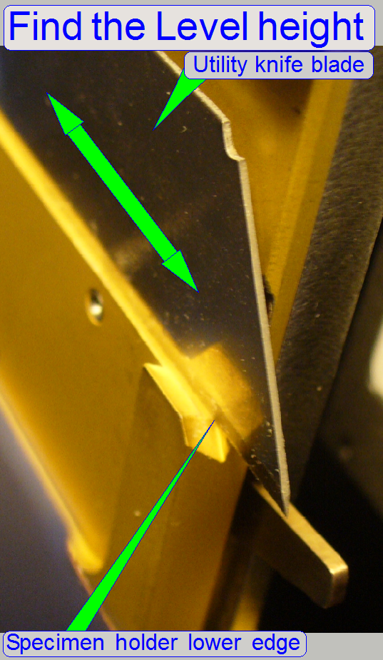
9.
Update the value of the parameter
“InsertSlidePositionX” in the section [SlideLoading] of the file
“MicroscopeConfiguration.ini” and save the file.
10. Check
the slide insert position with the widest and thickest slide; insert it with
the slide loader manually.
11. If the
slide lower edge hits the specimen holder lower edge, add to the value of the
parameter ‘InsertSlidePositionX’ 100 steps.
12. If the
thickest and widest slide will be inserted strong (the slide clamp has no gap),
reduce the value of the parameter ‘InsertSlidePositionX’ by 100 steps.
![]() “Adjust the slide
clamp lifter position”
“Adjust the slide
clamp lifter position”
Check
or adjust the position and height of the inner finger
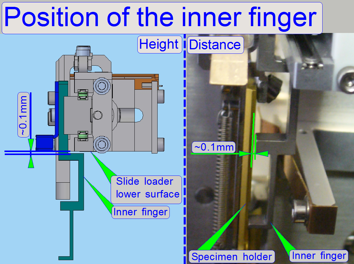 Requirement
- This adjustment
assumes that the value of the parameter “InsertSlidePositionX”
is found correctly.
- The “Position
of the magazine unit” and the “Position
of the specimen holder fixing fork” is found correctly.
Task
- If the moving
part of the slide loader is moved from the position over the magazine into
the specimen holder or vice versa, the right hand edge of the inner finger
should pass the specimen holder without hitting it, otherwise, the gap
should be not more than 0.1mm.
- Adjust the height
of the inner finger in relation to the slide loader lower surface so; that
the surface can be passed safely, otherwise, the gap should not be more
than 0.2mm.
Height of the
inner finger
- Loosen the
mounting bolt of the inner finger and adjust the height as shown on the
right.
- Check the
correct height by moving the slide loader moving part manually.
![]() Check or
define the value of the parameter “DefaultPositionX”
Check or
define the value of the parameter “DefaultPositionX”
Position of the inner finger
The position of the inner finger in relation to the edge of the specimen
holder is adjusted by the use of a fitting plate, situated on the mounting
surface of the inner finger; this adjustment is mostly not done in the field!
If the inner finger hits the edge of the specimen holder or if the gap
is too much, please check the position of the magazine unit and check also the
correct position of the specimen holder fixing fork first.
![]() “Check the
magazine unit position” and “Position of
the specimen holder fixing fork”.
“Check the
magazine unit position” and “Position of
the specimen holder fixing fork”.
Adjust
the inner finger vertical position
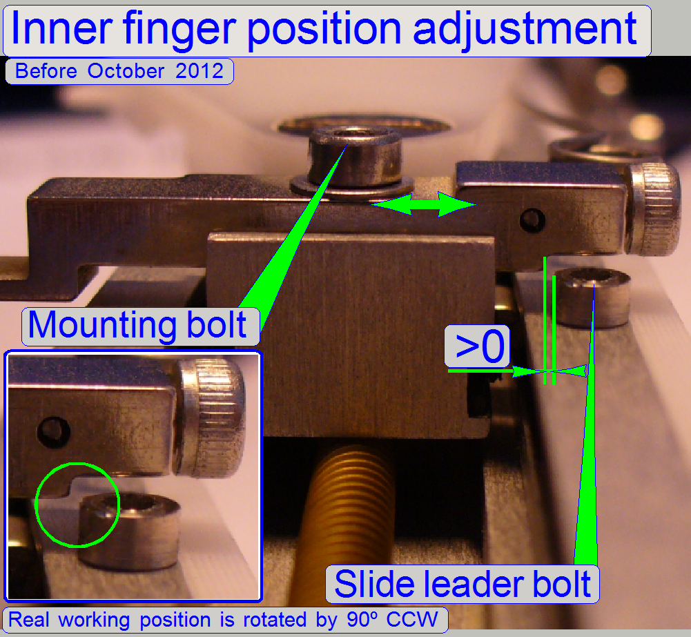
The version of
the inner finger is before October,
2012.
Check
· Move
the slide loader from the outer end position to the inner end position and vice
versa manually. Check the gap of the slide leader bolt in relation to the inner
finger.
· Check the behavior by moving the slide loader
moving part manually first and then with the service program also; hitting the
bolt must not be experienced.
Task
· Adjust
the inner finger height so, that the slide leader bolt is even passed by the
inner finger if the slide loader moving part is moving.
Adjustment
· Move
the moving part of the slide loader until the inner finger stays in the near to
the slide leader bolt.
· If the
inner finger can not pass the slide leader bolt, loosen the mounting bolt of the
inner finger and adjust a small gap.
· Adjust
the gap also, if the gap is too much, more then 0,1mm.
Set the slide
insert position in Y-direction; define “InsertSlidePositionY1”
Requirements
- The hardware limit “ObjectGuideYMin” ≤ -500 steps.
Task
- Set the start position for the slide insert procedure in
Y-direction.
InsertSlidePositionY1
= -500steps
· Update
the value of the parameter “InsertSlidePositionY1” in the section
[SlideLoading] of the file “MicroscopeConfiguration.ini” and save the file.
Remark
This position is not critical. In earlier delivered
systems this value was 400steps by default. Please, use now always the value of
-500 steps, if possible.
Adjust
the final insert position in Y-direction
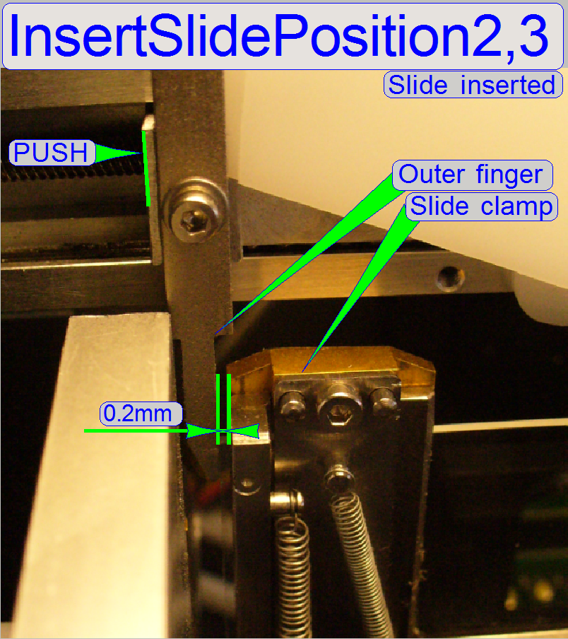
Requirements
- “InsertSlidePositionY1” ≤ “InsertSlidePositionY2,3”
Task
Set the value
for the parameters “InsertSlidePositionY2” and “InsertSlidePositionY3” (often
named as “InsertSlidePositionY2,3”) so, that the specimen holder is never
touched during slide insertion.
· Remember,
that both parameters must have always the same value!
1.
Set the positions Y-Home1,2 and X-Home1,2
of the X-Y-Stage.
2.
Set the X-direction to the value of the
parameter InsertSlidePositionX.
3.
Set the Y-direction to the value of the
parameter InsertSlidePositionY1 (nominal =-500 steps).
4.
Push the slide loader moveable part
manually, until the slide clamp of the specimen holder is reached by the outer
finger.
5.
Adjust the specimen holder Y-position
(service program, Y-direction) so, that the outer finger of the slide loader
has a gap of about 0.2mm to the slide clamp of the specimen holder and the
slide loader moveable part is fully pushed into the specimen holder. An
accuracy of 100 steps is enough.
6.
The right value for the parameters
“InsertSlidePositionY2,3” is found if the slide loader is fully pushed into the
specimen holder (check this behavior manually) and a minimal gap exists between
slide loader outer finger and slide clamp of the specimen holder.
· If the
gap is too much, the slide might touch the side wall of the magazine channel.
7.
Update the value of the parameters
“InsertSlidePositionY2” and “InsertSlidePositionY3” in the section
[SlideLoading] of the file “Microscope Configuration.ini” with the same value
and save the file.
Define the value
of the parameter “RemoveSlidePositionY”
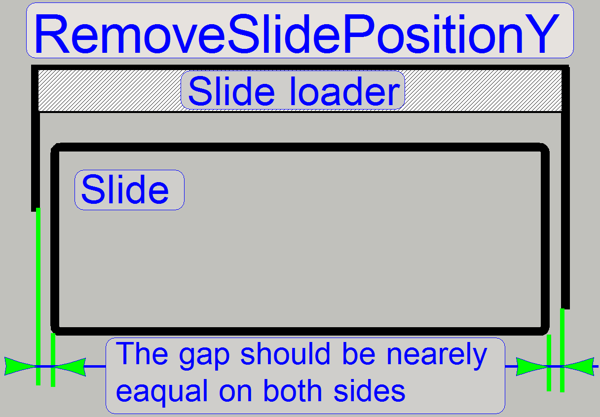
Add
six hundred steps to the value of the parameter “InsertSlidePositionY2”.
RemoveSlidePositionY
= InsertSlidePositionY2 + 600 steps
Update the value of
the parameter “RemoveSlidePositionY” in the section [SlideLoading] of the file
“MicroscopeConfiguration.ini” and save the file.
Define the value
of the parameter “RemoveSlidePositionX1”

“RemoveSlidePositionX1” = “Level height” -150
steps.
See also: Adjust the slide insert position in X-direction
Update the value of the parameter “RemoveSlidePositionX1”
in the section [SlideLoading] of the file “Microscope Configuration.ini” and
save the file.
If the slide clamp lifter is mounted:
“RemoveSlidePositionX1
= level height -150 steps.
Update the value of the parameter
“RemoveSlidePositionX1” in the section [SlideLoading] of the file “Microscope
Configuration.ini” and save the file.
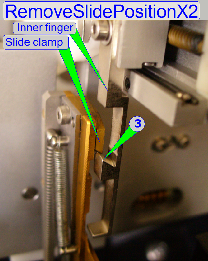 Define the value of the parameter
“RemoveSlidePositionX2”
Define the value of the parameter
“RemoveSlidePositionX2”
- There are two possibilities to define the value of the parameter “RemoveSlidePositionX2”, depending on
the used type of the inner finger.
If the earlier developed inner finger type
is present (scanners, delivered before Oct. 2012)
1. Define
the value for the parameter “RemoveSlidePositionX2” so, that the edge (3) of
the inner finger (or the runway of the slide clamp lifter) passes the slide
clamp easily, if no slide is inserted and the slide loader moves backward.
2. Update
the value of the parameter “RemoveSlidePositionX2” in the section
[SlideLoading] of the file “MicroscopeConfiguration.ini” and save the file.
If the newer inner finger type (since
October, 2012, with slide clamp lifter) is present
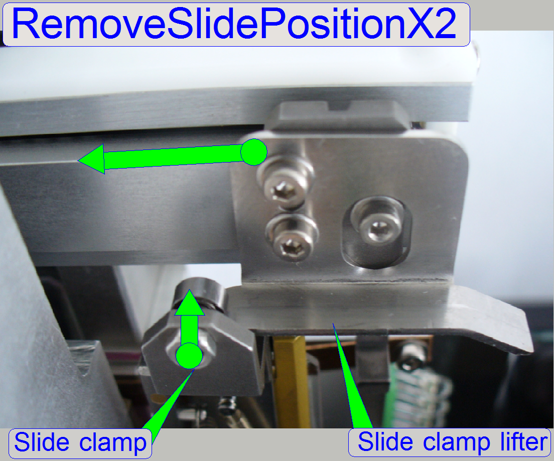 The values of the parameters “RemoveSlidePositionX1” and “RemoveSlidePositionX2”
are identical.
The values of the parameters “RemoveSlidePositionX1” and “RemoveSlidePositionX2”
are identical.
Set: Value of “RemoveSlidePositionX2” = Value of
“RemoveSlidePositionX1”
Remark
If there is no slide present
in the specimen holder, the slide lifter has also to pass easily the “Slide clamp
lifter ball bearing”! Therefore, a difference of some 100steps is allowed to
fulfill this requirement.
Update the value of the parameter
“RemoveSlidePositionX2” in the section [SlideLoading] of the file
“MicroscopeConfiguration.ini” and save the file.
Check the position of the slide leading spring
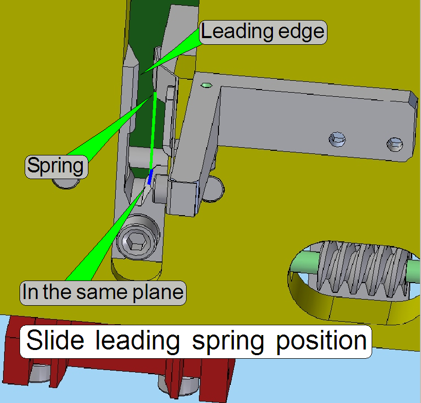
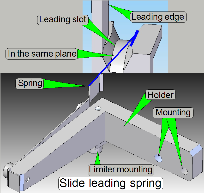 The slide leading spring should be
in the same plane as the slide leading slot edge, in opposite of the slide
leading edge as shown.
The slide leading spring should be
in the same plane as the slide leading slot edge, in opposite of the slide
leading edge as shown.
The distance of the leading spring surface to the slide
leading edge is about
- If the thickest
allowed slide dimension with cover slip will be inserted, the
spring should even not touch the cover slip!
Adjust the slide clamp lifter
position
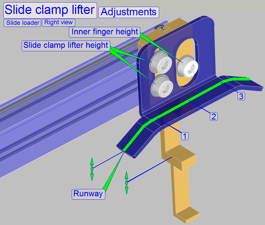
- This adjustment assumes that the value of the parameter “InsertSlidePositionX” is defined
correctly.
As discussed above, the slide clamp
lifter opens the slide clamp
during slide insertion.
Adjust the position of the slide clamp lifter so, that
the slide clamp is
fully opened during insertion of the thickest and
widest slide but the specimen holder should not be pulled upward.
Therefore, a small movement upward (about 0.1 … 0.2mm) of the slide clamp
should be possible in the positions 1, 2 and 3 of the runway.
1.
Insert the thickest and widest slide manually.
2.
Move the slide loader manually in the
direction of the specimen holder until the linear part of the clamp lifter is
reached (1) and the slide inner edge stays over the slide fixing ball bearing.
3.
Loosen the clamp lifter mounting bolts and
adjust the position of the clamp lifter so, that the the slide fixing ball bearing is
even not touched by the slide (a gap of about 0.1mm) exists and the slide
should not falling out, then tighten the clamp lifter bolts.
4.
Move the slide loader manually to the
middle (2) and the end (3) of the linear part of the slide clamp lifter’s
runway and check the gap in these positions also.
5.
Check in all three positions the gap of
the “Lifter ball bearing in relation to the run way of the slide clamp lifter;
a gap of at least 0.1 … 0.2mm is required, so straining of the specimen holder
and the parallelogram can be avoided.
1.
Checks with the service program
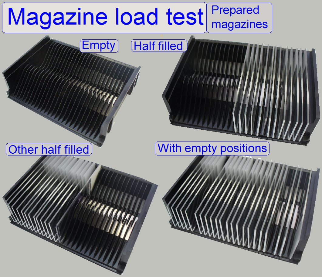
Check the magazine load procedure by using empty, half
filled and fully filled magazines (shown on the right).
· If the
magazine is placed into the input stack, the sensor “Tray hall
The magazine load procedure should be executed without
stumbling of the magazine; the magazines moving downward smoothly and the
feeder wheel engages the rack of the magazine easily.
· During
this test, only 1 magazine should be in the input stack at a time!
· If
stumble of the magazine during any load procedure occurs, please adjust the “Magazine position for the slide insert -
removal operation” more precise.
· Check
also the magazine(s) and its rack
During unload of the magazine, the magazine should
move into the output stack smoothly and evenly. Arrived in the output stack,
the magazine supporters should work correctly!
If 9 magazines are placed in the output stack, the
state “Output stack full” should be shown by the sensor!
· Check
this behavior with the service program and move the magazine in the 9th
position a little bit up and release it again; move the last magazine a little
bit sideward also.
· In all
cases, the state “Output stack full” should be detected clearly.
2.
Check the magazine load operation with the test program
· Use
the magazines, prepared in the previous check also with the “Magazine load test”, the
requirements are the same.
We assume the test “Check the magazine load - unload operation” is finished correctly.
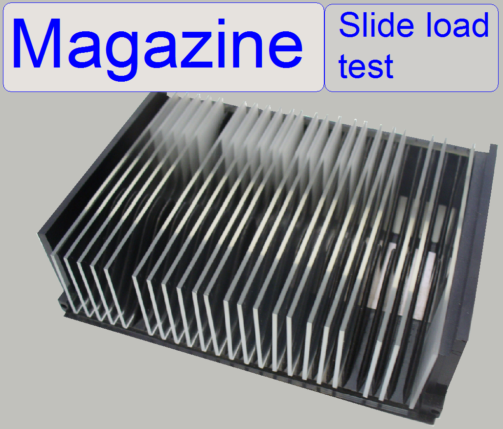
 Finally test the
slide insert and removal actions with all the delivered magazines and different
slide sizes and slide shapes. This test should include the thinnest, thickest,
smallest and largest allowed (metal) slides. Test the slide insert and removal
action also in magazine slide positions without slide (empty positions).
Finally test the
slide insert and removal actions with all the delivered magazines and different
slide sizes and slide shapes. This test should include the thinnest, thickest,
smallest and largest allowed (metal) slides. Test the slide insert and removal
action also in magazine slide positions without slide (empty positions).
Prepare the magazines for
the test
Fill all available magazines with slides and execute
the slide insert and removal test. In each magazine, there should be several
places without slides in different slide positions.
Meanwhile the slide loading
test is in progress, check the following actions visually:
· Please use always a protective
eye wear if the
slide loading test is in progress and you are looking closely at the loading
procedure! It may happen that a slide can fly in peaces during the process,
even if the adjustment is incorrect!
1.
During the magazine load action the
magazines moving downward smoothly and evenly.
2.
The magazine input sensor is attached the
magazine is moved to the first slide position (see also the chapter “Magazine input
sensor”).
During slide insertion
3.
The slide is inserted smoothly and evenly,
without bangs and stronger (more force requiring) sound, even if the thickest
slides with the maximal width of 26.00mm are inserted.
4.
The smallest slides should be hold
correctly.
5.
The outer finger does not touch the slide
clamp of the specimen holder if the slide is fully inserted.
6.
If the slide loader moves backward the
upper part of the slide clamp is not touched, even if slides with the maximal
width of 26.00mm are inserted.
During slide removal
7.
The inner finger crosses the slide clamp
if there was an empty position in the magazine.
8.
If the 9th magazine is present
in the output stack and the last slide of the 10th magazine is
removed from the specimen holder, the message “Output stack full” must occur!
![]() “Mistakes and abnormal or faulty behavior during slide insertion”
“Mistakes and abnormal or faulty behavior during slide insertion”
Magazine load and
unload test, slide insert and removal test
Start the program “SlideScanner.exe” with the service
password; the menu “Service” appears.
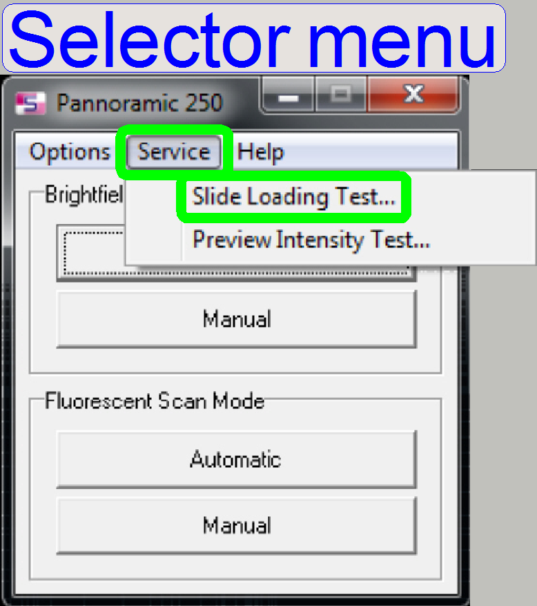
Select the option “Service” and “Slide loading test”;
the combined “magazine load / unload” (1, 2) and the slide insert / removal (3,
4) test will be selectable.
·
Insert one or more magazine(s) into the
input stack.
Watch video: Magnet
disc during magazine load_P250
Magnet
disc during magazine unload_P250
Watch video: Magazine load_P250
Magazine unload_P250
Slide insert
test_P250
Slide clamp
lifter_P250
Magazine load and unload test
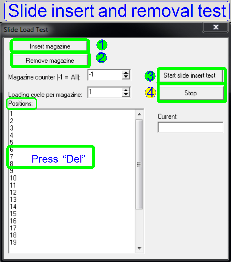
By pressing the button “Insert magazine” (1) the
magazine is moved from the magazine input stack into the magazine feeder
channel and if the magazine is detected by the left magazine sensor, the magazine
is moved to the first slide position of the magazine.
By pressing the button “Remove magazine” (2) the
magazine is moved in direction to the output stack until the right magazine
sensor is even passed, the sensor is in the released state.
The magazine feeder motor rotated the magnet disc one
turn backward and checks the right magazine sensor again. If the right magazine
sensor is attached, the magazine unload position is found and the magazine is
moved into the output stack.
By pressing the button “Slide insert test” (3)
1.
If no magazine is present in the feeder
channel:
The magazine load
procedure is executed as described above (1).
The slides will
be inserted into the specimen holder and a few seconds later it will be removed
into the magazine.
If all (selected) slides of the magazine passed the slide
insert and removal procedure, the magazine is feed to the output stack; see (2)
above and the next magazine with slides will be loaded. The procedure will be
repeated until magazines are present in the input stack or if the button “Stop test” (4) is pressed.
2.
If a magazine is already present in the
magazine feeder channel:
The magazine is
moved until the first slide position of the magazine is reached and then the
slide loading procedure is executed.
· Please use always a protective
eye wear if the slide
loading test is in progress and you are looking closely at the loading
procedure! It may happen that a slide can fly in peaces during the process,
even if the adjustment is incorrect!
If the button “Stop test” (4) is
pressed, the test stops only, if the actual slide insert and removal action is
finished.
In emergency conditions, the switch “Emergency power off”
should be switched off.
Positions:
In the table “Positions” slide positions of the
magazine can be disabled from the slide insert and removal procedure by easily
deleting the appropriate line from the table. If the test is loaded again from
the start menu, all slide positions are available again.
·
If
all the tests and checks are fulfilled correctly, adjustment of the magazine unit
is finished.
Mistakes and abnormal or faulty behavior during slide insertion
The following or other faulty behavior can also occur
if dust, paraffin residues or bits of broken glass are in the magazine slide rail
or on other parts, needed for the slide insert and slide removal procedure.
1.
The slide cannot be inserted, the slide
hits the specimen holder and the action is aborted.
§
Check the plane of the slide leading edge
with the specimen holder right hand edge (Magazine
unit position; position of the specimen holder fixing fork).
§
Check the slide
leading slot bottom in relation to the lower edge of the specimen holder (“InsertSlidePositionX”).
§
Check the position of the slide loader outer
finger in relation to the magazine rail (Adjust
the position of the magnet disc).
§
Check the slide dimensions of the used slide.
2.
Some slides are inserted well, but some
times a big bang can be listened or even cracking the slide on the top:
§
Check the slide
leading slot bottom in relation to the lower edge of
the specimen holder; see also: “InsertSlidePositionX”.
§
Check the position of the slide
loader outer finger in relation to the middle of the magazine rail.
§
Check the
height position of the inner finger.
§
Check the slide dimensions of the used slide.
3.
Some slides are inserted well, but some
times a big bang can be listened or even cracking the slide on the bottom:
§
Check the slide
leading slot bottom in relation to the lower edge of
the specimen holder.
§
Check the position of the slide loader
outer finger in relation to the middle of the magazine rail.
§
Check the slide dimensions of the used slide.
4.
The slide insert procedure is done, but
often or some times, the slide is slant inserted and falling down onto the
truss.
§
Check the plane of the slide
leading edge with the specimen
holder right hand edge; see also “Adjust the magazine
unit position”.
5.
During slide insertion a stronger (more
force requiring) sound can be listened, even in the second phase of slide
insertion or the slide is removed before the slide insert procedure is finished
(the slide loader time out was running out).
§
Check / adjust the slide insert position
in X-direction; define the value for the parameter “InsertSlidePositionX”
again; the value of this parameter is mostly too much.
§
Check the slide dimensions of the used slide.
6.
If the slide will be inserted, a bang can
be listened always or on some slides, the Inner finger cannot cross the slide
clamp or is in collision with other parts of the specimen holder.
§
Check the plane of the slide
leading edge with the specimen
holder right hand edge.
§
Check the slide
leading slot bottom in relation to the lower edge of the specimen holder (“InsertSlidePositionX”).
§
Check the
height of the inner finger.
§
Check the slide dimensions of the used slide.
7.
The outer finger touches the specimen
holder during the second part of slide insertion is done.
§
Check / adjust the slide insert position
in Y-direction; define the value for the parameter “InsertSlidePositionY2,3” again.
8.
The slide is touching the sidewall of the
magazine channel if the specimen holder is in the Y-position -800 steps.
§
Check / adjust the slide insert position
in Y-direction; define the value for the parameter “InsertSlidePositionY2,3” again.
9.
If the slide loader is returned to the
outer position (after slide insertion), the lower edge of the slide loader
inner finger touches the upper part of the specimen holders slide clamp.
§
Define the value of the parameter “DeafultPositionX” again and check the
height position of the inner finger; check also the correctness of the limit “Xmax”.
§
Check the slide dimensions of the used slide.
Mistakes
and abnormal or faulty behavior during slide removal
10. The
inner finger cannot cross the slide clamp if there was an empty position in the
magazine.
§
Define the value of the parameter RemoveSlidePositionX2 again.
List of Parameters and explanation
In the following list the parameters for the magazine
unit, the slide loading and slide removal are collected; the parameters are
situated in the file MicroscopeConfiguration.ini.
Non relevant sections like [ScanCamera], [PreviewCamera],
[PreviewAndBarcodeScanning] are left out. A short explanation of the parameters
should help to understand the meaning of the parameter values.
Please make a security backup of the file MicroscopeConfiguration.ini
before parameter values are modified!
The description is based on the software
version 1.15.
· The
path of the file MicroscopeConfiguration.ini, in the version with the operating
system Windows® 7 is:
C:\ProgramData\3DHISTECH\SlideScanner\MicroscopeConfiguration.ini
· in the
version with the operating system Windows® xP is:
C:\ Documents and
Settings\All Users\Application Data\3DHISTECH\SlideScanner\
MicroscopeConfiguration.ini
· All of the shown unit specific parameter values are examples and for
information only; these are different from unit to unit of the same type also.
Please never use the example values!
More information can also be found in the
chapter “Handling
the INI files”
[Version]
CurrentInifileVersion=1.9; actual
MicroscopeConfiguration.ini file version since MScan.exe version 1.9 or higher,
do not modify
[Microscope]
SerialNumber=xxxxxx; a
six digit number defines the serial number of the P250, so the file
MicroscopeConfiguration.ini is assigned to the hardware.
MicroscopeType=3DMic9; 3DMic9
means Pannoramic 250
ScanCameraType=; not
used
PreviewCameraType=CVrmc_m8_pPro; the preview camera
BarcodeReaderType=PreviewCamera
LoaderType=SL_9Mag_25Slide_Sensor_Vertical; Magazine unit type, see also: Configure
…
CameraChangerType=CC_3DH_2Pos; see also: the camera changer
ReflectorTurretType=RT_3DH_10Pos_Belt; see also: P250_turret_unit
BrightfieldLightSourceType=FlashLight2010; see also: The brightfield
light source
BrightfieldLightSourceType=FlashLight2012; see also: “The ND filter unit” and “Upgrade to the
software version 1.16”
ObjectiveChangerType=OC_2Pos; see also: Configure …
ObjectGuideXYZType=OGXYZ_FLASH3; see also: Configure the
X-Y-stage unit
FlashUnitType=FlashUnit_Type2; see also: Configure electronics
components
NDFilterType=NDType2; see
also: The ND-filter
unit
PreviewLightType=PreviewLightUnitType_Type2; see also: Configure the preview unit
PowerSwitchBoardType=PowerSwitchBoard_Type1; see also: Configure
electronics components
[HardwareLimits] The number of steps
is defined without mechanical jamming
See
also: Find the hardware limits for the X-Y-stage unit and the Focus unit,
ObjectGuideXMin=-700; number of steps allowed in
negative direction from Home1,2
ObjectGuideXMax=30000; number of steps allowed in
positive direction from Home1,2
ObjectGuideYMin=-1200; number of steps allowed in
negative direction from Home1,2
ObjectGuideYMax=89200; number of steps allowed in
positive direction from Home1,2
FocusDeviceMin=-1760; number of steps allowed in
negative direction from Home1,2
FocusDeviceMax=2750; number of steps allowed in
positive direction from Home1,2
ReflectorTurretMin=-300; not used in the belt driven
version
ReflectorTurretMax=58700; not used in the belt driven version
StepSizeXinMicrometer=1
StepSizeYinMicrometer=1
ScannableAreaPositionXMin=1900; see also “define the scannable area”
ScannableAreaPositionXMax=26400; see also “define the scannable area”
ScannableAreaPositionYMin=36989; see also “define the scannable area”
ScannableAreaPositionYMax=89200; see also “define the scannable area”
CameraChangerVT_Min=-1010; see also “CC find the hardware limits”
CameraChangerVT_Max=1090; see also “CC find the hardware limits”
ObjectGuideXYTimeDelayBeforeImageAcquisition=0; A
value between 0 and 30 ms can help to eliminate vibrancy after stage movement
before the scan camera picture is taken; 0 means no wait (or the parameter is
missed), 30ms is recommended.
[SlideLoading]
DeafultPositionX=29600; can be the value of
“ObjectGuideXMax”-100 steps; the slide loader inner finger should not touch the
slide clamp if the slide is inserted and the slide loader movable part is
moving backward to the slide position of the magazine.
DeafultPositionY=18000; the focus pin moves on
the metal part of the specimen holder and the X-motor limits can be reached. Do
not modify.
InsertSlidePositionX=700; the specimen holder
position for slide insertion
InsertSlidePositionY1=-500; the specimen holder position
for slide insertion at the beginning
InsertSlidePositionY2=600; the final specimen holder
position for slide insertion.
InsertSlidePositionY3=600; the final specimen holder
position for slide insertion.
SlideHolderReleasePositionY=8000; the slide tightener is released; the slide
clamp is forced to hold the slide.
RemoveSlidePositionX1=-300; the specimen holder position for
slide removal at the beginning
RemoveSlidePositionX2=000; the specimen holder position for
slide removal at the 2. Phase
RemoveSlidePositionY=1100; the specimen holder Y-position
for slide removal
[SlideLoader]
SlideLoaderTimeout=1200; do not modify
SlideLoaderDelayTimeBeforeSensor=300;
If the outer sensor is attached it should be released after 300ms; do not
modify
MagazineFirstSlidePosition=18; number of turns to reach the first
slide position of the magazine, do not modify
MagazineRemovePosition=85; number of turns to reach the
magazine remove position, do not modify
MagazineFirstSensorPosition=0; do not modify
MagazineLastSensorPosition=85; do not modify
StackerTimeout=10000; the magazine load
sensor should be attached in less than 10s, do not modify
StackerDelayTimeBeforeSensor=100; do not modify
StackerPreloadTime=2900; do not modify
MagazineFeederMoveTimeAtPreload=0; do not modify
MagazineFeederTimeout=1000; less than 1000ms for one turn is
allowed, do not modify
MagazineFeederDeadTime=100 do not modify
MagazineFeederDelayTimeBeforeSensor=100;
do not modify
MagazineFeederTryCount=10; do not modify
MagazineFeederDelayTimeBeforeMagazineSensor=300; after 300 ms check the left or right
magazine sensor; do not modify
SlideCountPerMagazine=25; P250=25; other values are not
allowed
[Focus]; at
the end of the file
FocusPositionMin=-300
DefaultScanPosition=-300
SlideInsertPosition=-300
SlideRemovalPosition=-300
SlideFeederPosition=-300
SafePosWhileMoving=-300
CondenserCoverOn=2750;
CondenserCoverOff=-1760
NoFocusPinOnTheObjectHolderX=27000
NoFocusPinOnTheObjectHolderY=16000
[ReflectorTurret]
MotorPositionDelta=3200
[ObjectiveChanger]
ObjectiveChangerTimeout=7000
[CameraChanger_Zeiss]
CameraChangerTimeout=500
[CameraChanger_VT]
Position1=-1000
Position2=1080