Tools, Facilities, Requirements
For technicians!
This chapter contains tools, facilities and requirements to
install, repair and to adjust Pannoramic scanners and to clean optics.
Computer relevant configuration and software requirements are true
until the operating system Windows xP® and the software version 1.14 is used.
·
Relevant computer information since the software
version 1.15 or higher and the operating system Windows 7® 64bit is collected
in the chapter “Prerequisites”.
·
Tools used to cleaning optics
 Hexagon (hex) key wrenches
(metric)
Hexagon (hex) key wrenches
(metric)
Used in: All scanners
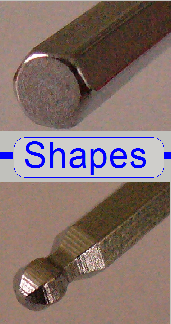
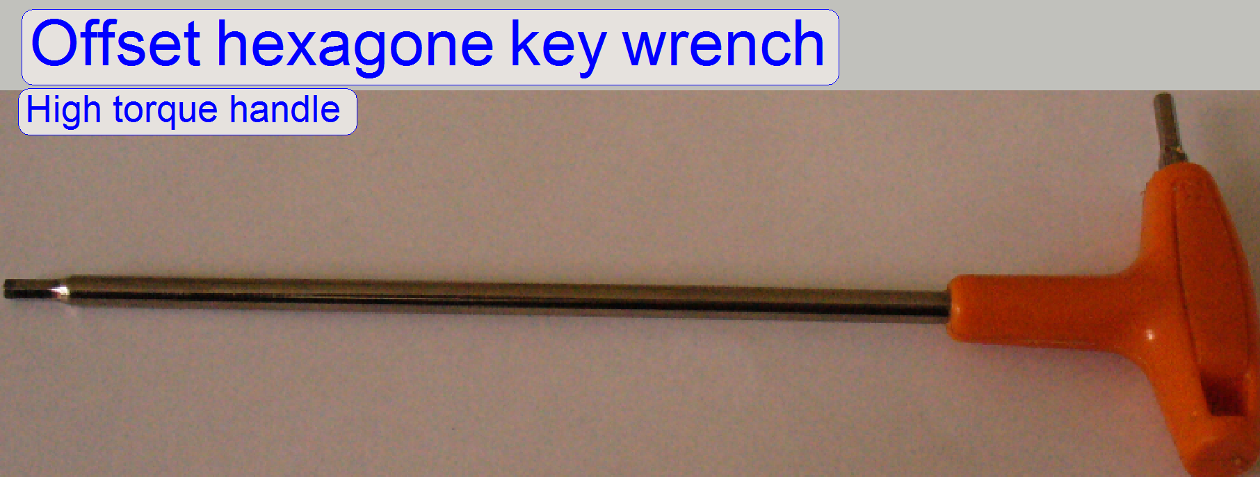
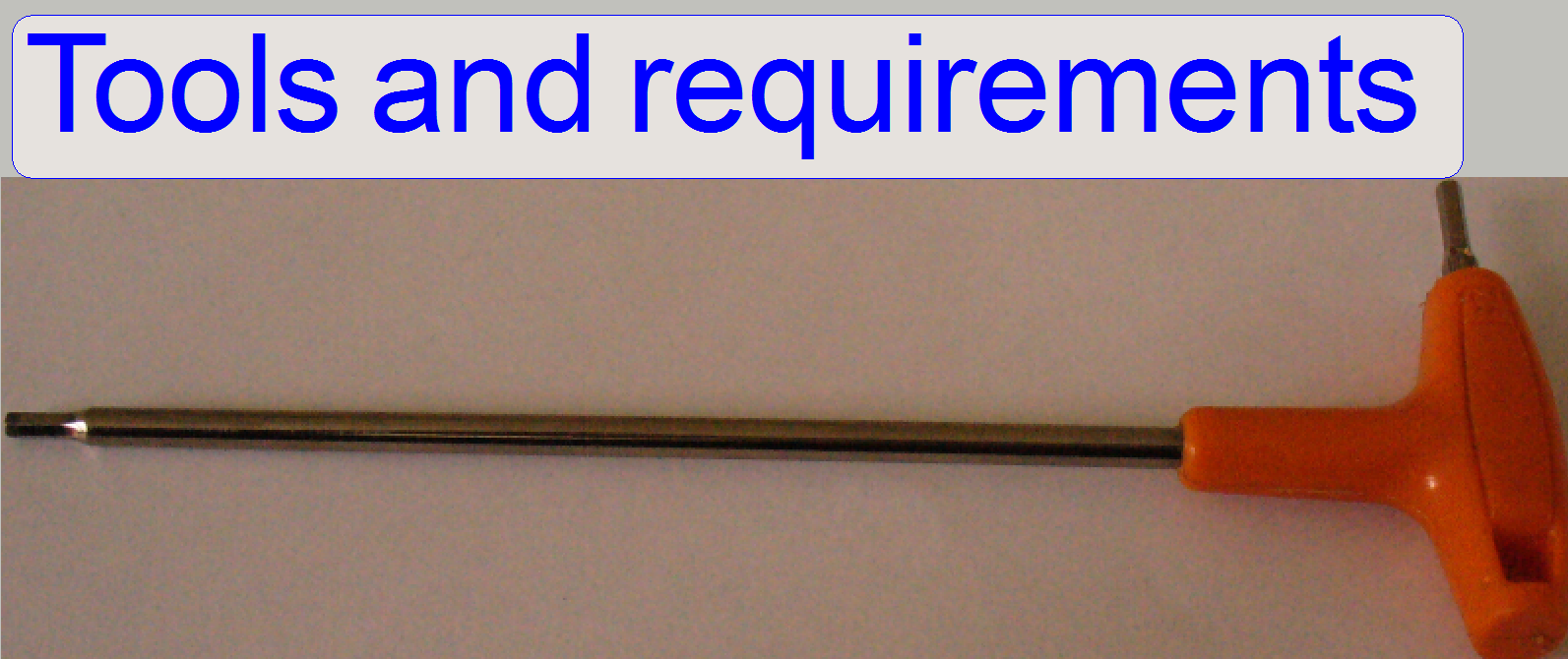
Hexagon key wrench
Ball point hexagon key wrench

Sizes: 0.9, 1.5, 2,
2.5, 3, 4 and 5mm metric.

All the mounting and adjustment bolts can be driven with one
of the key sizes, named above.
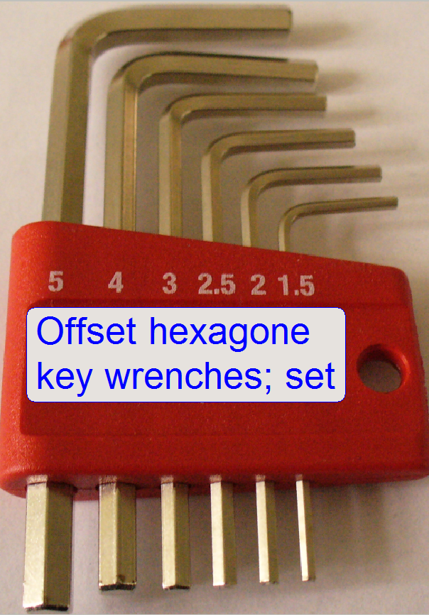
An
offset hexagon key wrench set is required; for the key sizes 1.5, 2.5 and 3 mm screw
driver type tools with handle are recommended. Furthermore, a ball point
hexagon key wrench in the sizes 2.5 and 3
mm offers advantage in some
situations.
·
Because the 0.9 mm hexagon key wrench is often not
included in any set, an offset hexagon key wrench 0.9 mm should be purchased separately.
Important
To tighten or loosen a bolt, use
always an (offset) hexagon key wrench, never a ballpoint hexagon key wrench!
PCON
In the scanner
Pannoramic Confocal key sizes of 6mm and 8mm are also required!

Screw drivers
In some cases screw drivers for “Cross head Philips® screws” are
used in the following sizes:
PH 00 60 mm
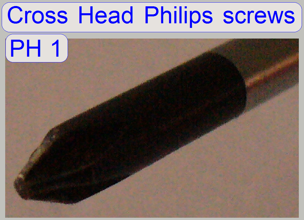 PH
0 60 mm;
PH
0 60 mm;
PH
1 80 mm;
PH
2 100 mm;
PZ
2 100 mm;
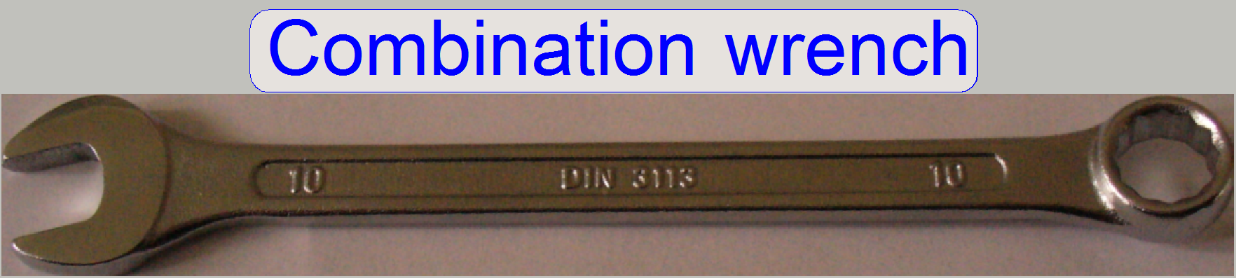 open and offset ring ends, chrome-plated; small heads
Used in: SCAN and P250
Size: 10 and 5.5 mm metric
Remark: The size 10 combination wrench is delivered with the SCAN scanner.
The 10th wrench is used to open / close the
cover locks and to loosen / tighten the shipping bolt in the SCAN scanner; the
truss nuts are also tightened with the 10th wrench.
The
5.5th wrench is used
to loosen / tighten the fixing nut for the chromatic aberration adjustment bolt
in the DESK.
open
end, small heads
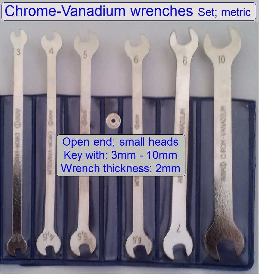
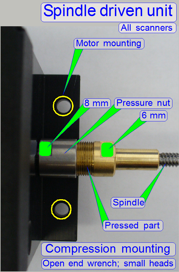
Used in: All scanners
To
loosen or tighten the compression-type connection of the spindle to the rotor,
2 additional metric
·
This connection occurs always on the spindle connection of newer
type X-Y-stage units and other kind of spindle driven units.
·
8mm open
end wrench, chrome-plated; small heads
·
6mm open
end wrench, chrome-plated; small heads
·
The thickness of the
wrenches is about 2mm.
Tweezers (recommended)
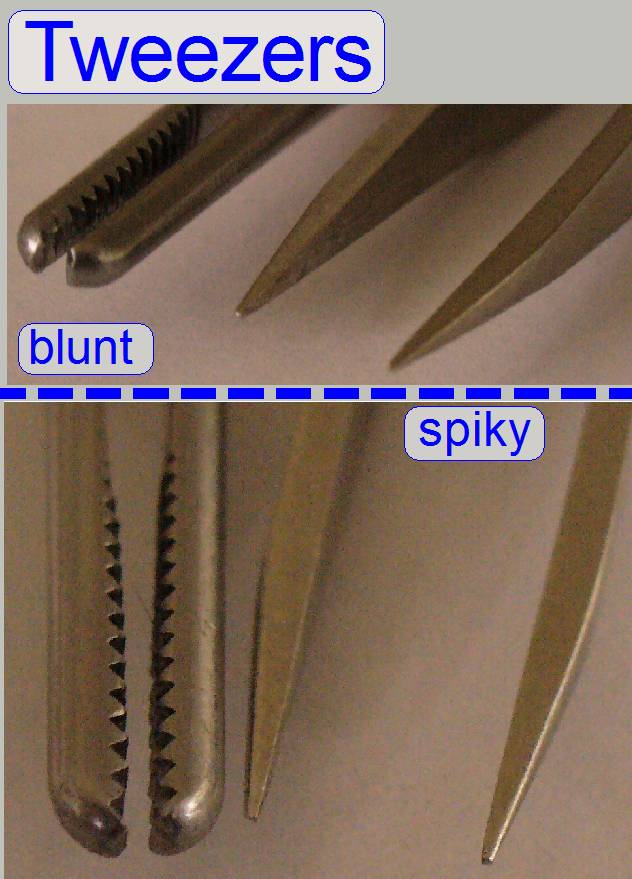
Used in: All scanners
Two types;
- fine and spiky,
- big and blunt
Flat nose pliers (recommended)
Used in: All scanners
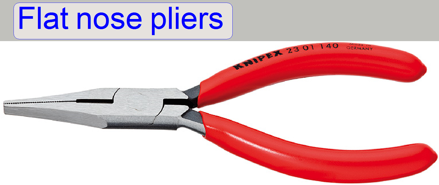
To hold bolts, nuts or other small pieces
flat nose pliers or any equivalent gripping pliers is recommended.
·
The
pliers should not be used to tighten or loosen bolts or nuts!
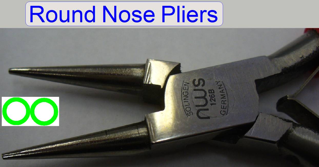
 Other pliers (recommended)
Used in: All scanners
For any kind of
electronics pliers see also:
· http://shop.nws-tools.de/index.php/en/electronic-tools.html
The shown pliers are
collected from:
· http://shop.nws-tools.de/index.php/en/electronic-tools/finish-72/economyline.html
All pliers have a length
of:
Length [mm] 120
Length [inch] 4 3/4


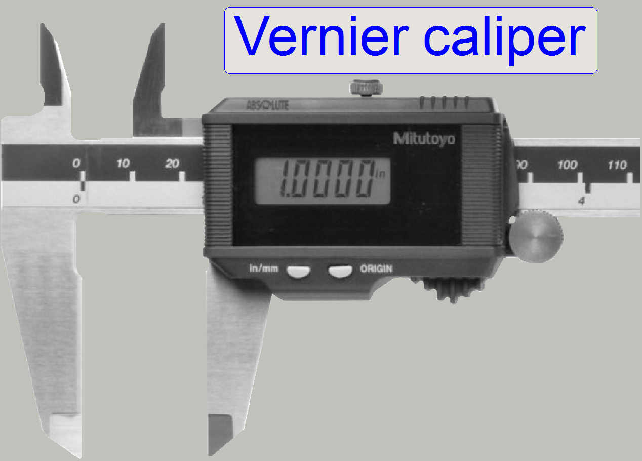
Used in: All scanners
For distance measuring, to check the
correct size of parts and the check of adjustments a digital caliper with a
nominal resolution of 0.01 mm and a length of 150 mm is recommended.
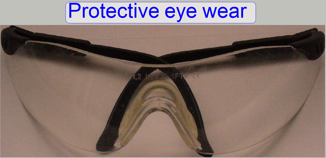
Protective eye wear
Used in: All scanners
Please use always a protective eye
wear if the slide loading
test is in progress and you are looking closely at the loading procedure! It
may happen that a slide can fly in peaces during the process, mainly if the
adjustment is incorrect!
Autocollimator and dovetail ring adaptor
Used in: P250, SCAN
and
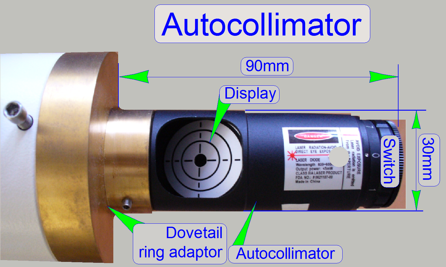
The
autocollimator is used to find
the correct filter position of the filter wheel in the turret unit.

Precautions
Never look directly into the beam of the autocollimator!
The LASER beam
has often a power of 0.01W only, but this is enough to harm the retina of the
eye!

Used
in: P250, SCAN and
The
light source is used to illuminate the field of view, if the fluorescent scan
modus is selected.
· For our purposes, we can also
use the user’s light source.
Precautions
Never look directly into the beam of the fluorescent light source!
The lamp emits also ultraviolet light with very high intensity. To prevent your
eyes from harm (damage) use always sun glasses with a high filter factor of UV
light if the fluorescent light source is switched on and you are adjusting the
beam mainly if the cover of the turret unit is removed. For further precautions
please, refer to the manual for the fluorescent light source you are using!

“X-Cite Series 120Q” and “Xcite120PC_UserGuide”
SOLA-SM-II-Light-Engine
Used in: P250, SCAN and
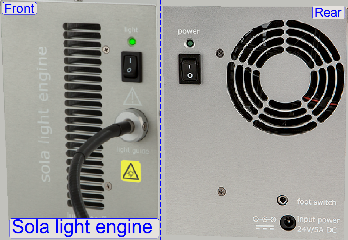
Sola-SM-II-Light-Engine®
offers a more cost-effective solution in relation to the HxP light engine® or
to the Lumencor SPECTRA light engine® and may be used in Fluorescent scan
sessions of any scanner type.
- Because the Light engine emits white
light, only single band filters can be used.

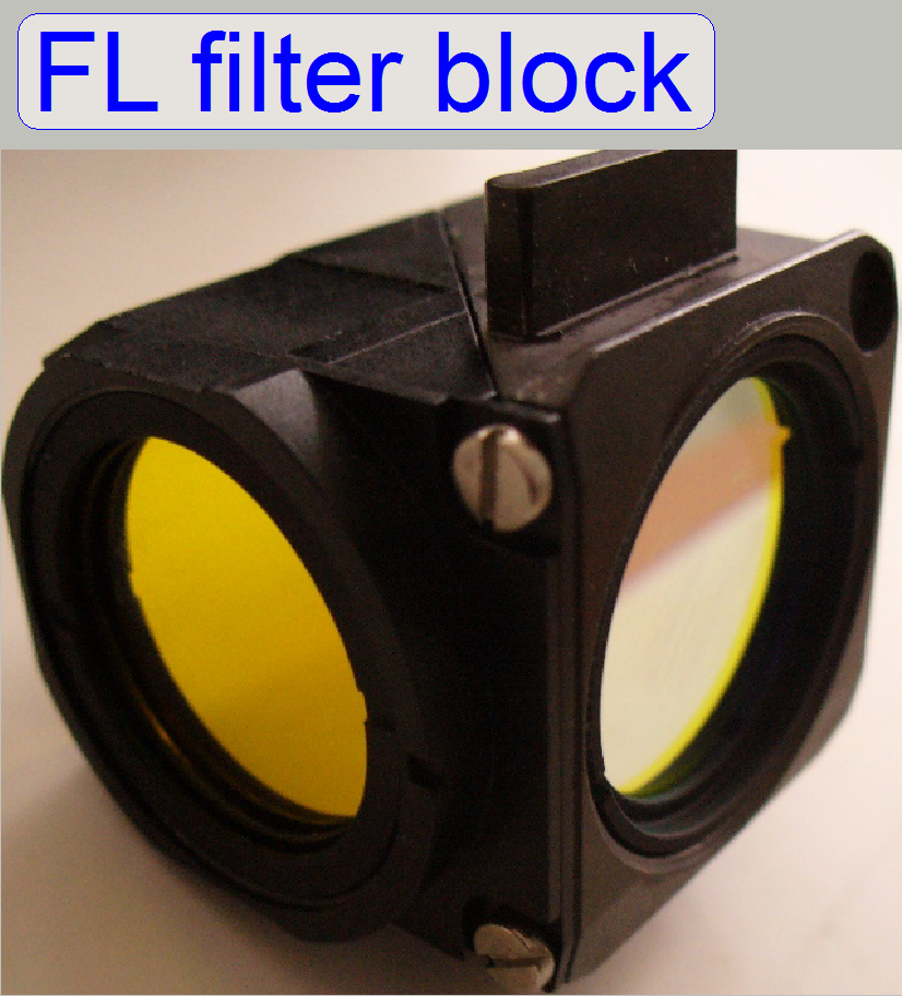 Used in: P250, SCAN and
A set
of filter blocks in the wave lengths red, green and
blue is used to adjust the fluorescent filter unit and to scan the fluorescent
tissue.
- The specified wave lengths of the
filter block and the exciting and emitting wave length of the stained
tissue have to match each other.
· For our purposes, we can also
use the user’s filter block(s).

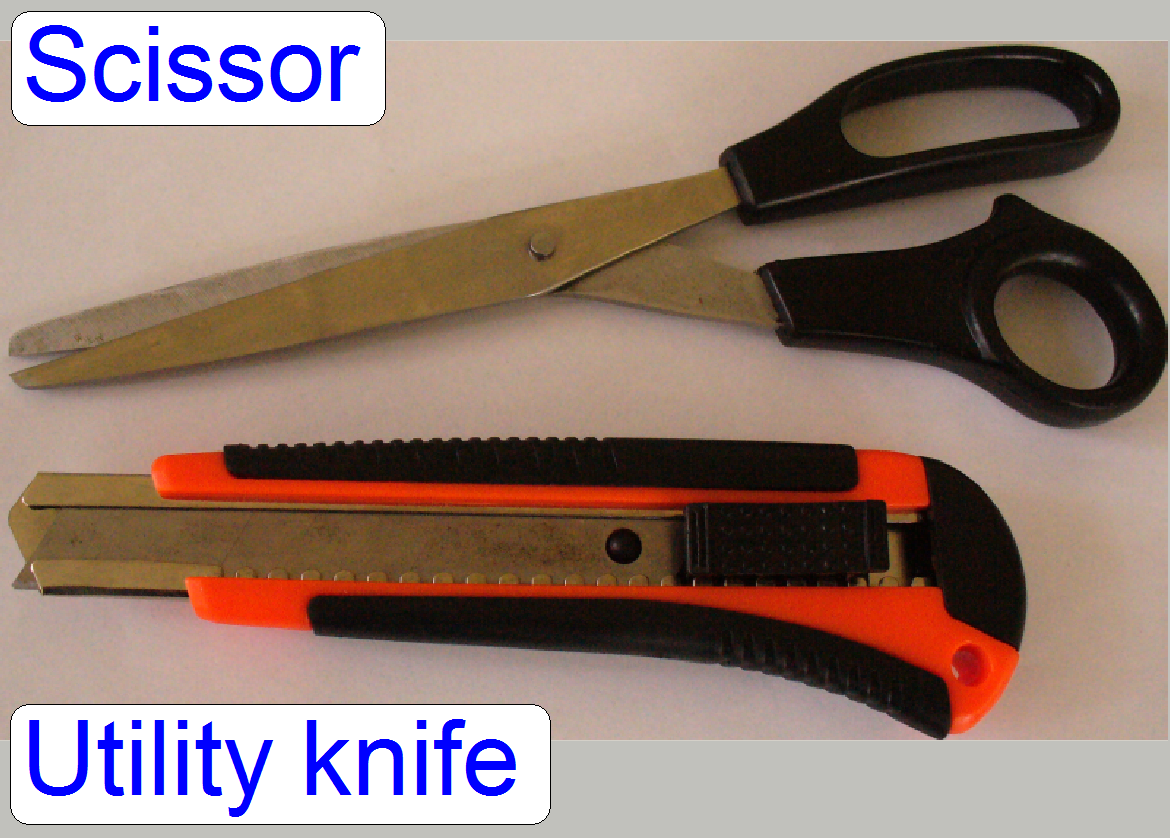
Used in: All scanners
To
cut labels and inscriptions a scissor with a blade length of at least 10 cm is helpful.
To cut strips and foils, to open
packaging and others, a utility knife is required.
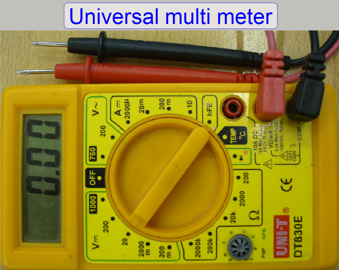
Used in: All scanners
To
check voltages and fuses and to measure resistances, any kind of multi meter can
be used; we recommend the use of the UNI-T DT830E or any equivalent type.

Used in: All scanners
To
remove bits of broken glass from the magazine channel, slide rails and from other
parts, paint-brushes in 2 cm and 4 cm width are often very helpful;
furthermore, any kind of dust can also be removed from the units by the use of
a brush.
Used in: SCAN,
The following configuration is true for
service purposes until the software version 1.14 and the operating system
Windows xP®.
Since the software version 1.15 and the
operating system Windows7® x64bit please use a configuration as described under “Computer
configuration and conditions” in the chapter “Prerequisites’
Processor: Intel
Pentium dual core, 2.6 GHz or higher
Ram: 4GB or
more
HDD: 400
GB or
more
USB 2.0 ports: 6 or more
VGA card: PCI
16x
FireWire ports: 1
FireWire extension card: 2 controllers
LAN controller and network connection
Monitor: 17” color
LCD or larger Resolution: 1024 x 768 or higher
Keyboard, Mouse
Barcode dongle
Following requirements are mainly based on software versions with
the operating system Windows®´xP 32bit until the software version 1.14. If an
operating system Windows® 7 x64bit is used, please refer to “Prerequisites” and “Software and driver
installation”
 Slide scanner program with dongle or actual
license file
Slide scanner program with dongle or actual
license file
·
Please
make a security backup of the file MicroscopeConfiguration.ini before parameter
values are modified!
The MicroscopeConfiguration.ini and the
MicroscopeSettings.ini are situated:
Before version 1.14.
The
*.ini files are found in the directory specified for the program
Slidescanner.exe or MScan.exe respectively.
Version 1.14.
The *.ini files are found in the directory:
C:\ Documents and
Settings\All Users\Application Data\3DHISTECH\SlideScanner\
All Users: this directory
is true if the SlideScanner software was installed for “All Users”; otherwise,
the software is installed to the user that was logged on during the install
procedure.
 Slide viewer program with dongle or
actual license file
Slide viewer program with dongle or
actual license file
The slide viewer program
is found in the directory, specified during installation.
 Service
program (SlideScannerService.exe or MService.exe) with actual license file
Service
program (SlideScannerService.exe or MService.exe) with actual license file
Important
·
Please make a security backup of the file
MicroscopeConfiguration.ini before parameter values are modified!
Versions before 1.14
The service program has to
be copied (is found) into the directory specified for the program
Slidescanner.exe / MScan.exe.
Versions 1.14. and higher:
The service program (the
entire service pack) has to be copied (is found) into the directory:
C:\ Documents and
Settings\All Users\Application Data\3DHISTECH\SlideScanner\
· See also above
“SlideScanner program”.
 Batch test program “b-Test.exe”
The test program
b-Test.exe can be used to define and run test routines to moving units
separately and in cycles.
The program works with predefined commands and these are arranged
as needed for the test. To create your own test sequence, no programming
knowledge is needed; the commands and steps are arranged by using logic.

The address of the addressable
unit can be
defined with the program “Serial.exe’.
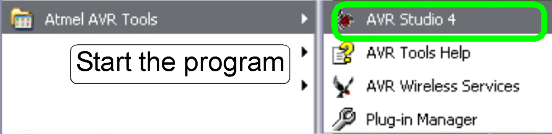
To upgrade the firmware of the stepper motor controller, start the
“Atmel AVR Tools” and “AVR Studio 4”.
Slide dimension check tool
Used in: PCON_S_M_D
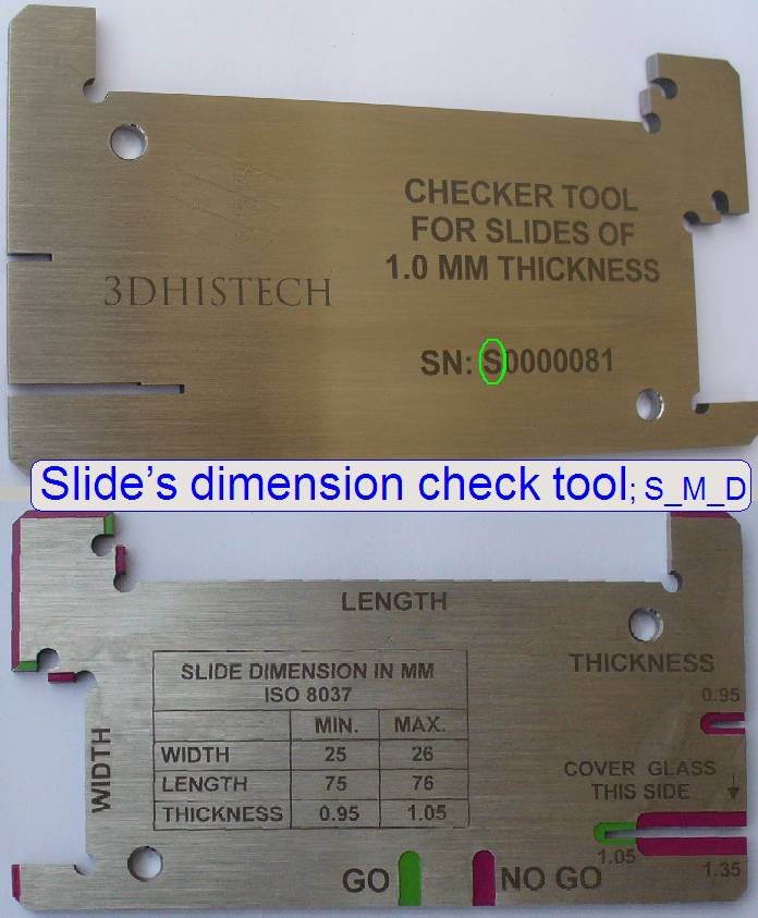
The
tool is delivered with the appropriate scanner since
January 2015!
The allowed slide dimensions are:
Length: 75.00 to
Width: 25.00 to
Thickness: 00.95 to
- If
the first character of the serial number is an “S” the tool
is used to check the slide’s dimensions for the scanners “PCON”, “SCAN”,
“MIDI” and “DESK””.
- If
the first character of the serial number is a “P” the tool
is used to check the slide’s dimensions for the scanner “P250”.
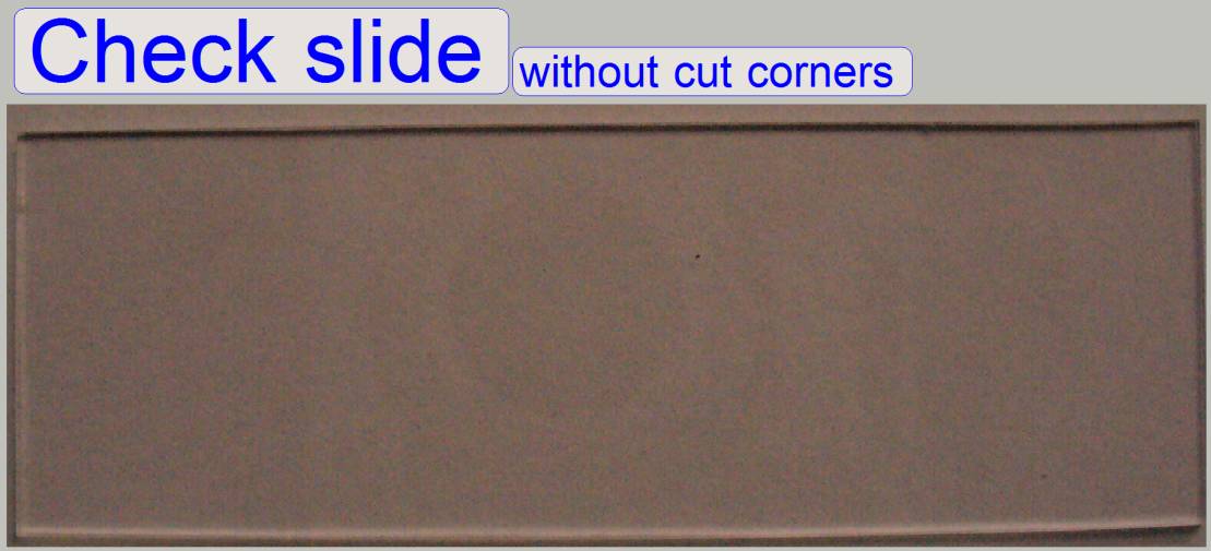
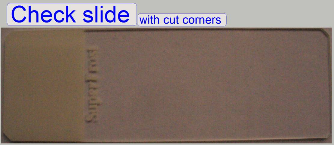
· Please
check the slide’s dimensions before filling the magazine or the tray with
slides!
Slide dimensions in DESK_II
Single width
Length: 75.00
to
Width: 25.00
to
Thickness: 00.95
to
Double width
Length: 75.00
to
Width: 50.00
to
Thickness: 00.95
to
Slide dimension check tool
Used in: P250
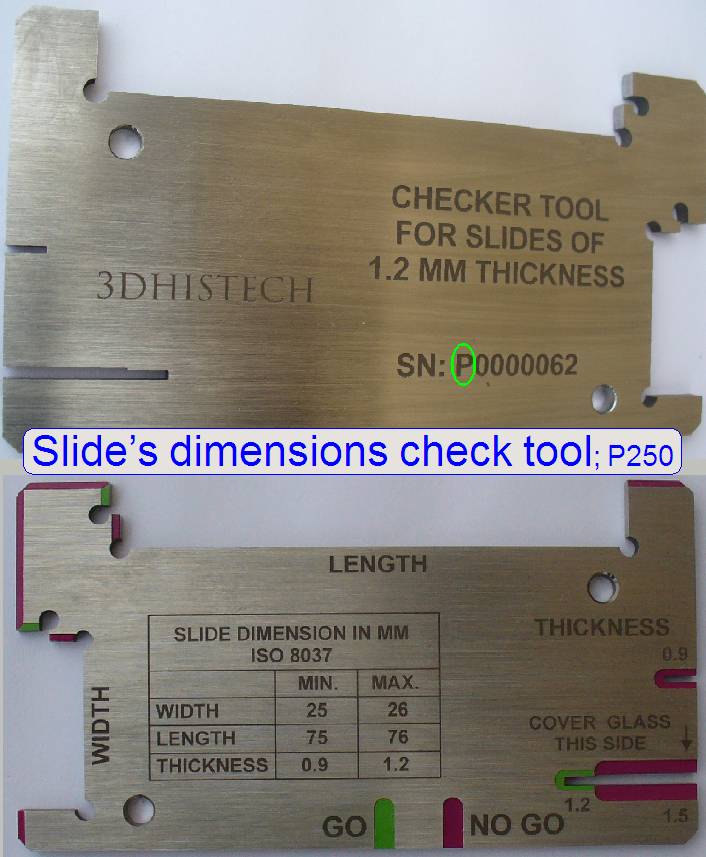 The tool is delivered
with the scanner since
January 2015!
The tool is delivered
with the scanner since
January 2015!
The allowed slide dimensions are:
Length: 75.00 to
Width: 25.00 to
Thickness: 00.95 to
- If
the first character of the serial number is an “S” the tool
is used to check the slide’s dimensions of the scanners “SCAN, “
- If
the first character of the serial number is a “P” the tool
is used to check the slide’s dimensions of the scanner “P250”.
· Please
check the slide’s dimensions before filling the magazine!
Recommended slides
 Used in: PCON, P250, SCAN,
Slide loading test: glass slides;
300 peaces (SCAN).
The slide loading test
for the SCAN and the
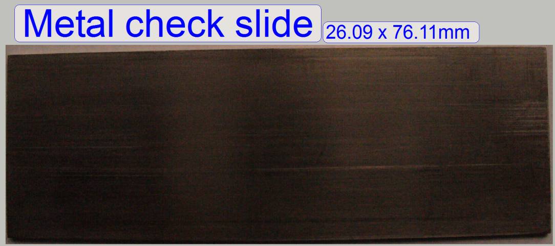 Metal etalon test slides
The allowed slide dimensions for the SCAN, the MIDI and the DESK are:
Length: 75.00 to 76.00 mm
Width: 25.00 to 26.00 mm
Thickness: 00.95 to 01.05 mm
To ensure, that the specified
slide dimensions can be loaded, a metal slide kit with 4 test slides was
created; the slides, if they are inserted, checking so the loadable slide
dimensions. The test kit contains the following dimension checks:
· The longest
and widest slide
· the longest
and smallest slide
· the shortest
and widest slide
· the shortest
and smallest slide.
Barcode
check slides
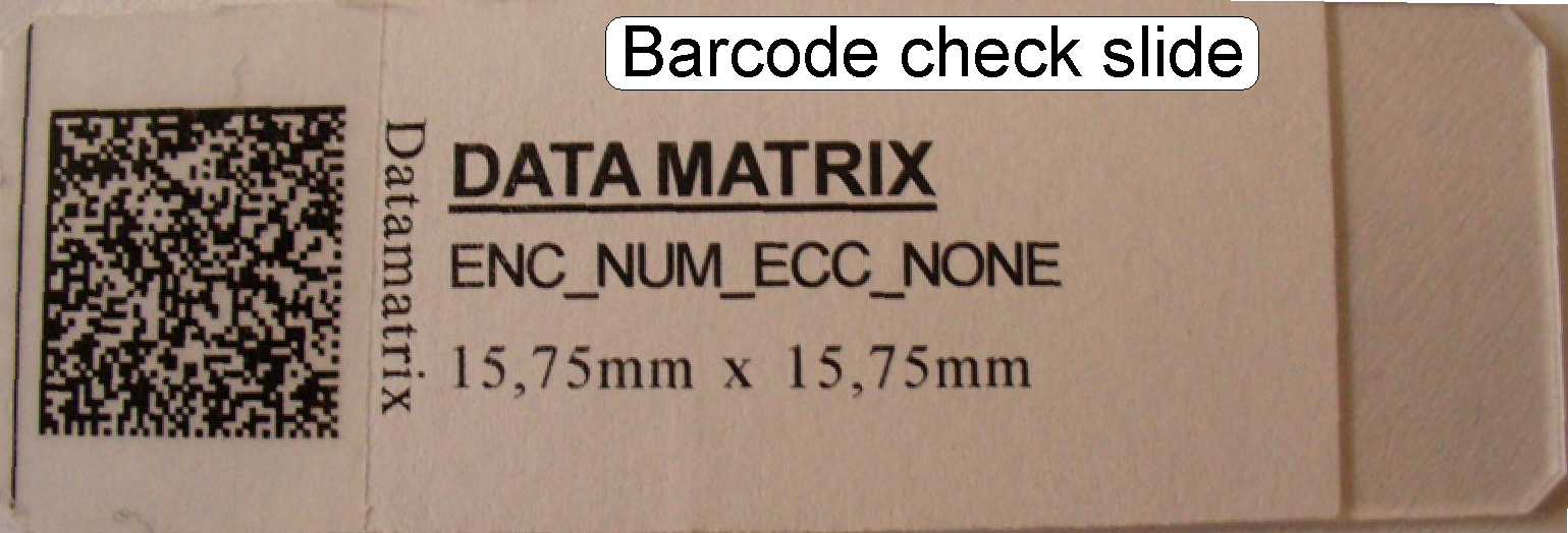
For barcode reading, a series of 19 check slides is used; the
check slides containing the different barcode types with the smallest, allowed
pixel size.
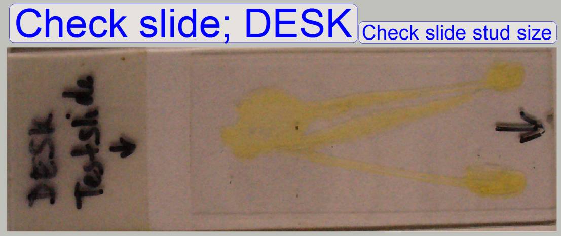 DESK, slide insert check
The slide stud in the DESK should be able to hold the thickest allowed
slide together with the cover slip (thickness = 0.17mm). Use this test slide to
check the slide stud size in the DESK.
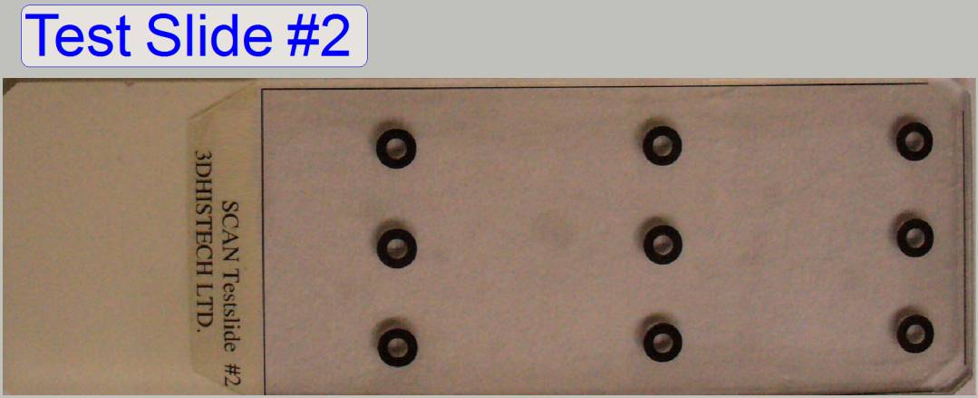 Test slide #2
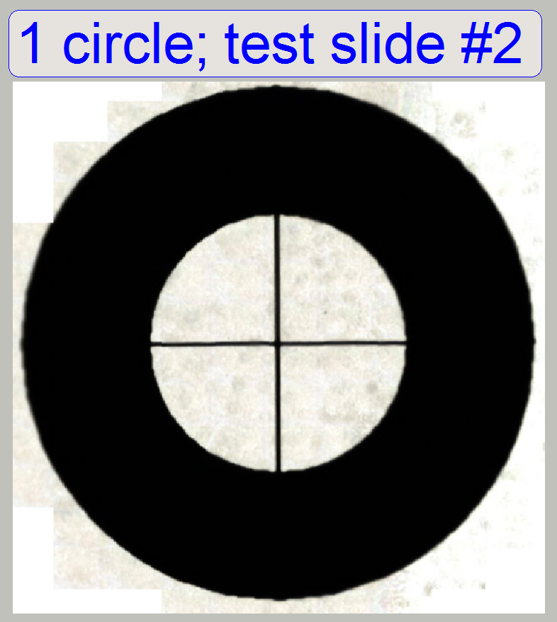
The test slide # 2 contains 9 circles; each circle has a cross in the
center. These crosses are marker positions for the preview
calibration program.
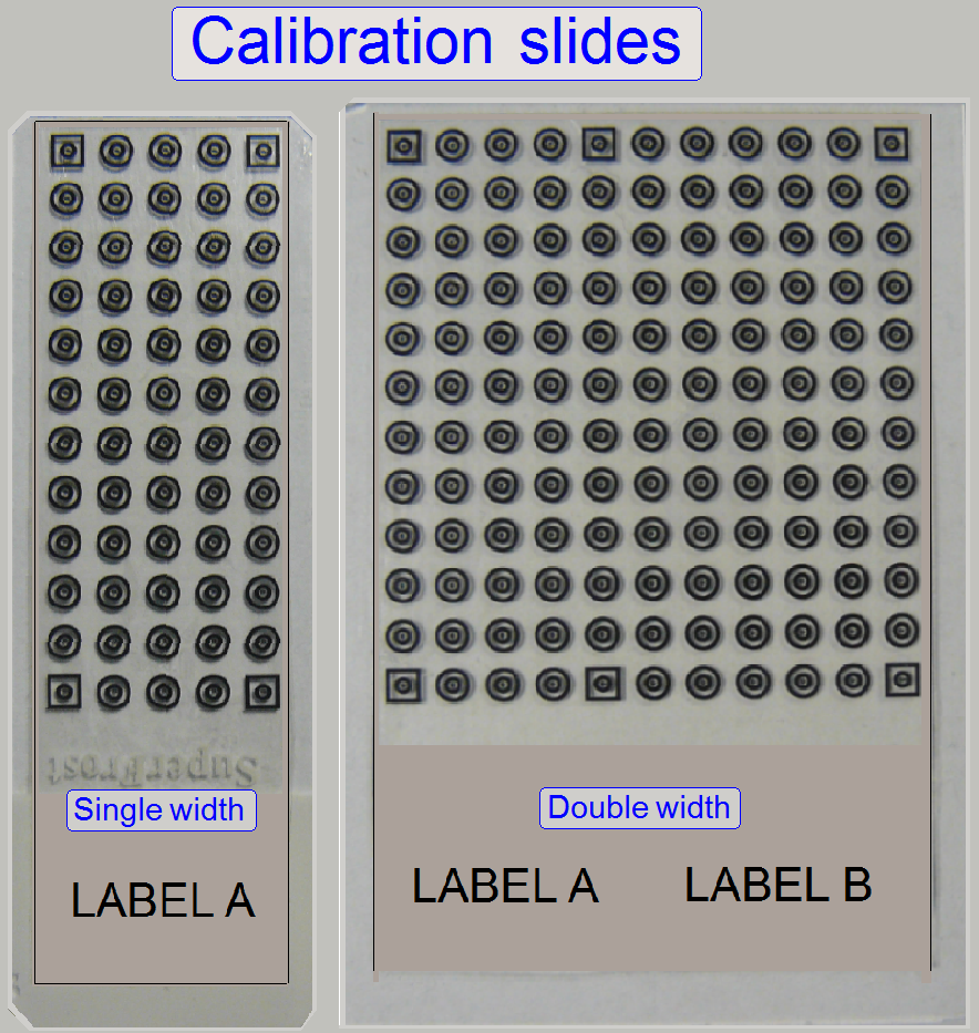
In S_M_D_II-type scanners a new preview calibration slide
is used.
The calibration slide exists in 2 versions, Single
width slide and double width slide.
In all scanners, the calibration is done with the
single width calibration slide.
In DESK_II the double width calibration slide is
used to check the preview calibration result.
Because a new, more precise preview calculation algorithm
is used, a new calibration slide is required, so post corrections after preview
calibration are minimized or eliminated.
Calibration slide Carl Zeiss # 474028
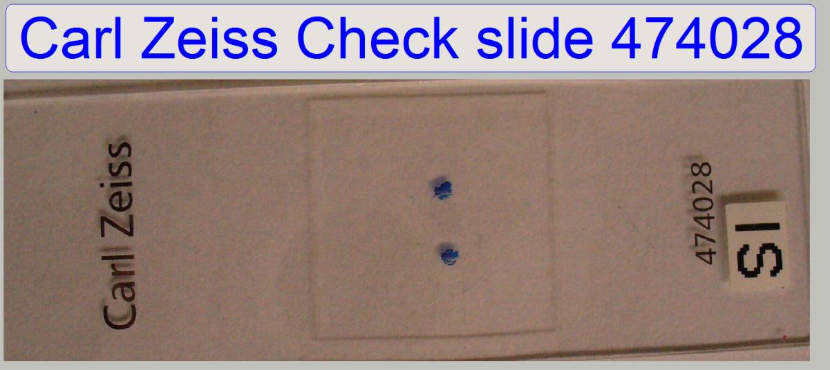
The calibration slide #474028 is used to correct the chromatic aberration and to check the inclination of the specimen holder.
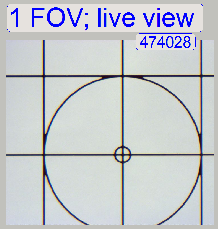
· Live view
with 20x objective and not zoomed
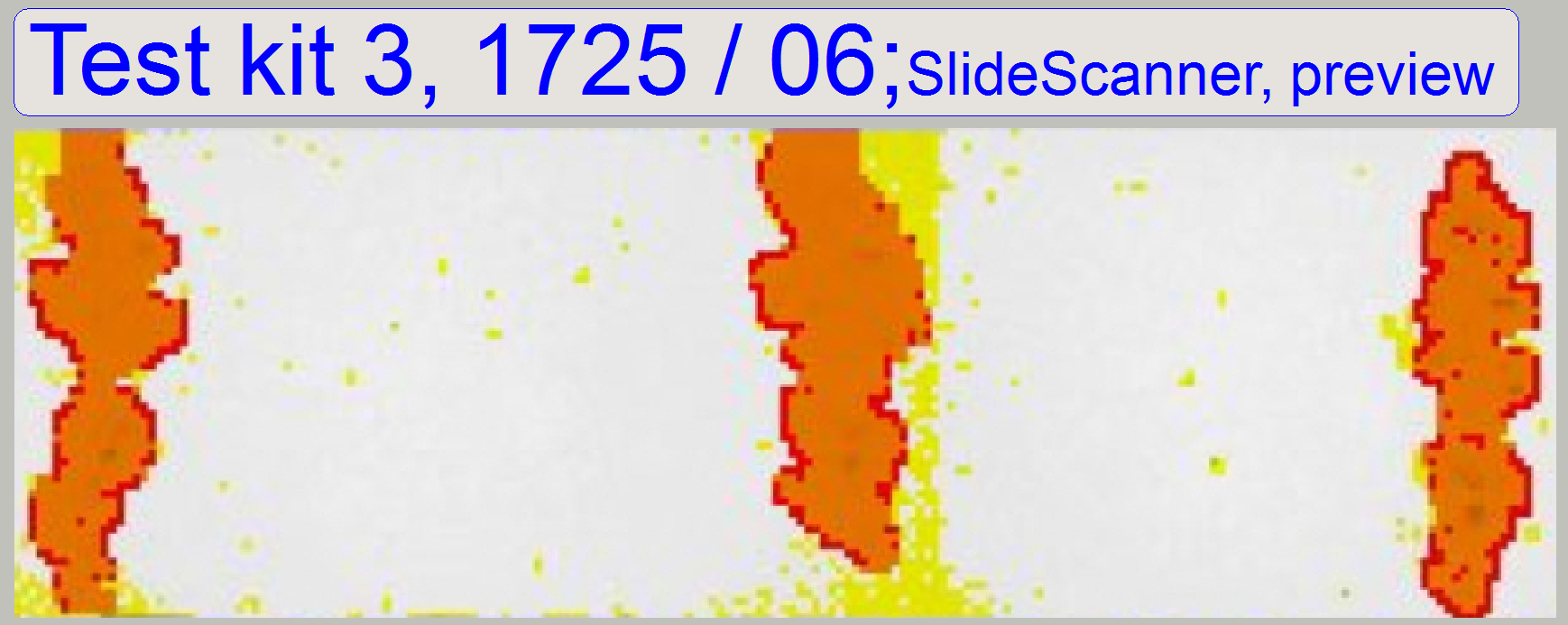
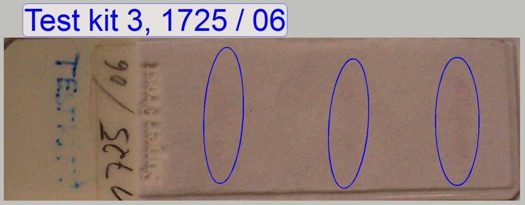 Test kit 3, 1725 / 06
The slide #1725 / 06 is very poor in contrast and therefore used to
check the preview quality.
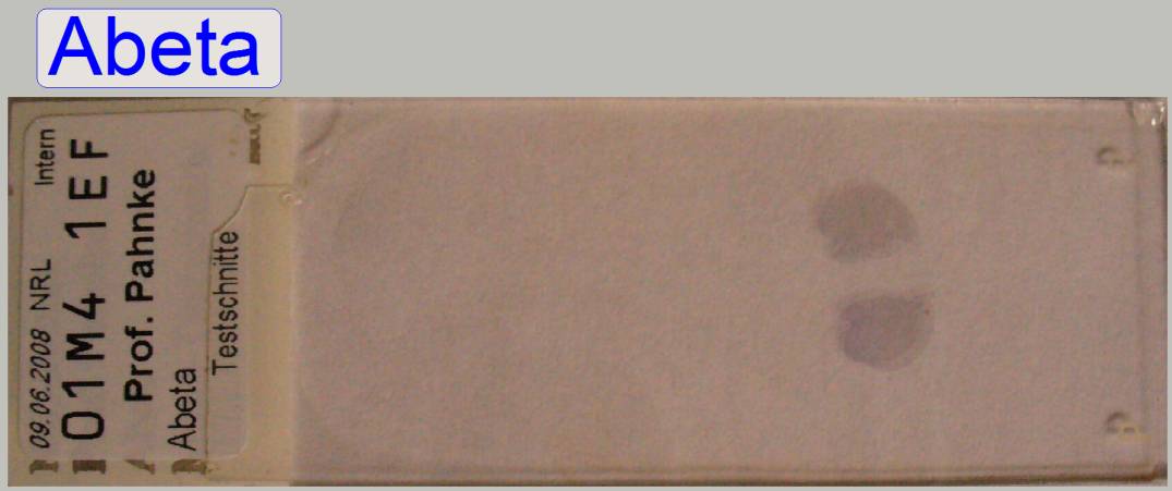
Test
slide Abeta

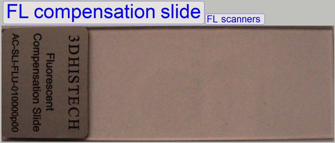 Fluorescent compensation slide
The fluorescent compensation slide is used to create a virtual
compensation image for the fluorescent scan procedure; it consists of a glass
slide and a foil.
·
Used in the SW versions 1.14 and 1.15 only
 Important
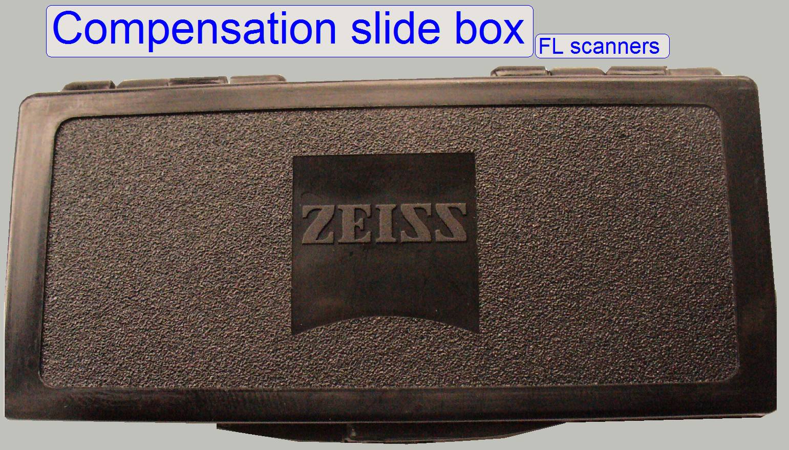
The foil is very light sensitive! Therefore, the
slide should be returned into the protecting box as soon as possible after the
fluorescent compensation image had been taken.
·
Used in the SW
versions 1.14 and 1.15 only
 FL scan check slide
Important
Fluorescent slides are very light sensitive!
Therefore, the slide should be returned into a light protecting box as soon as
possible after the fluorescent scan is finished.
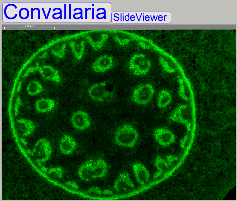
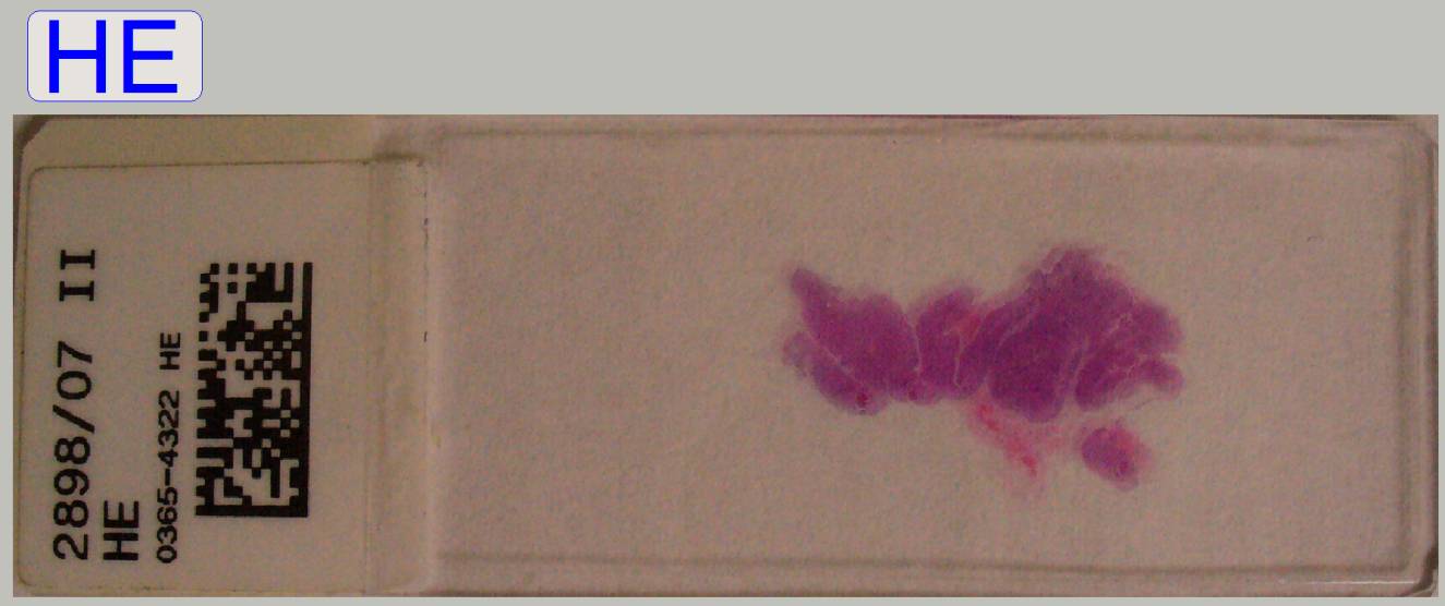
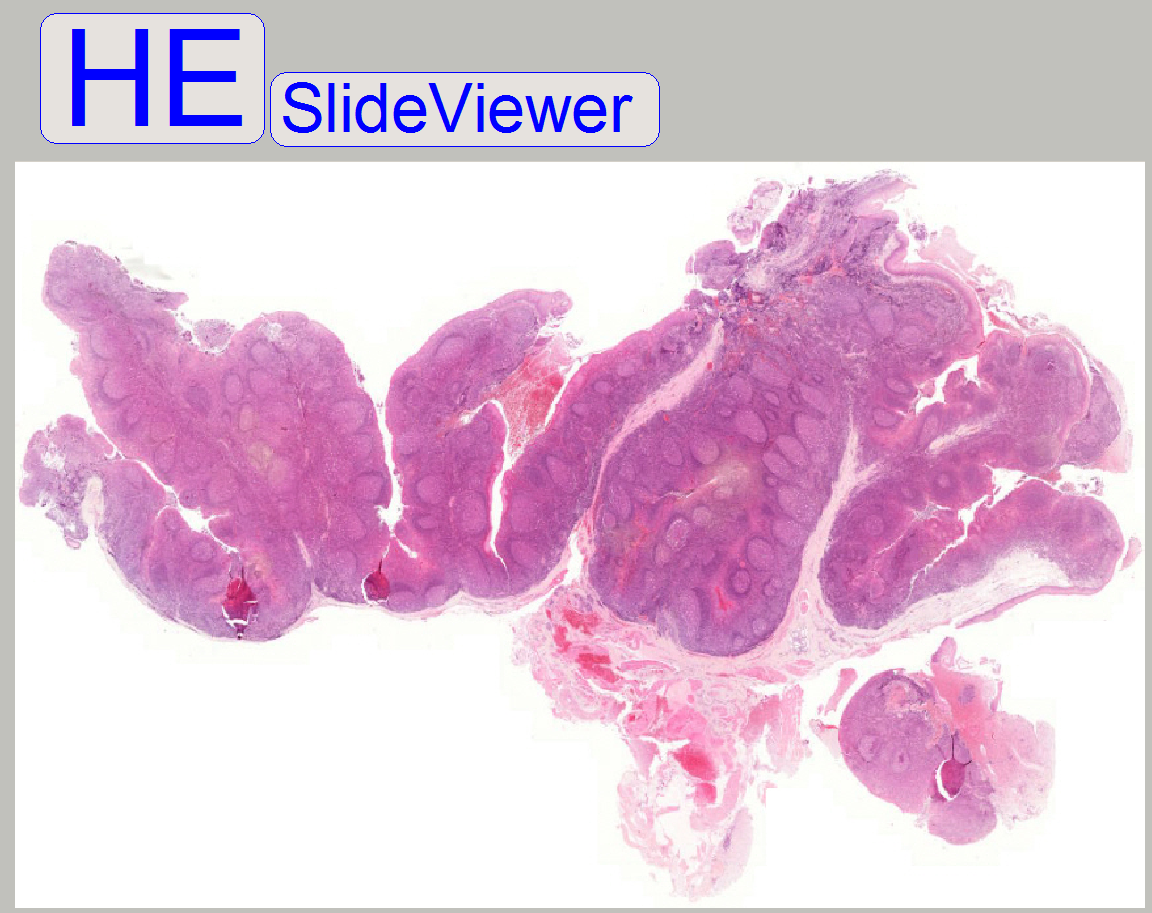
The slides “Abeta”, “HE”, Slide #1725 /
06 and “Convallaria” are used to check the scan quality in brightfield and
fluorescent scan mode.
Used
in: PCON, P250, SCAN,
See also: “Cleaning
optics”
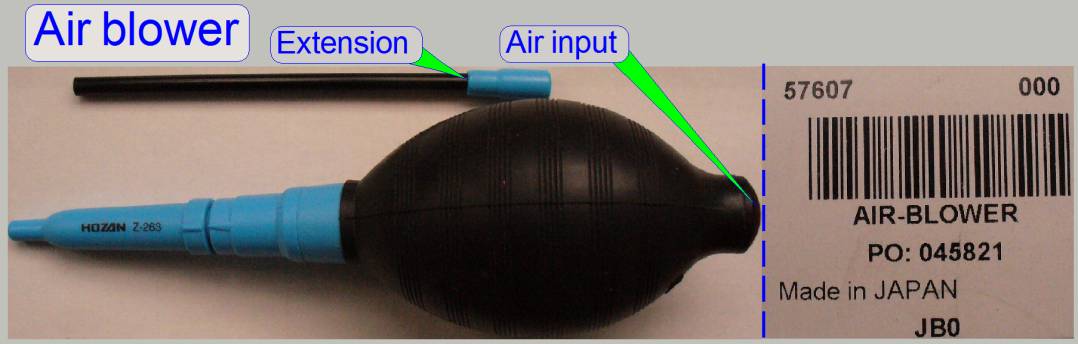 Manual air blower
By using a manual air blower, loosen dust
can be removed easily.
Do not
use canned air cleaner products for optics; the composition is often not
exactly known and may contain contaminations; these might damage the optics
surface or the coating. Furthermore, if a powerful air blow reaches the optics
surface, the existing dust particles on the optics may scratch the surface or
coating immediately!
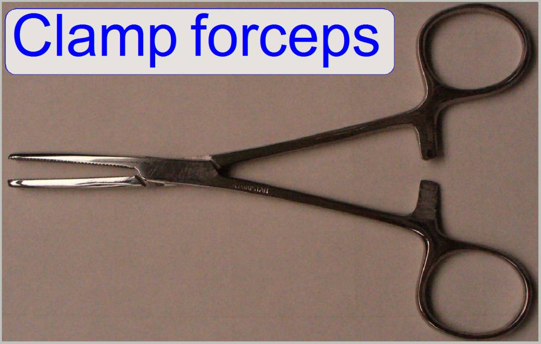 Clamp forceps
To grip and hold lens cleaning tissues or
cotton pads a clamp forceps is very helpful.
Plastic blade tweezers
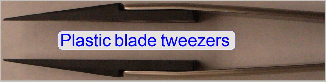
Any kind of cleaning materials like
cotton batting, cleaning tissues or cotton balls can also be hold by a plastic
tweezers.
The
cotton material to be hold should fully cover the peaks of the tweezers and
should keep a thick coating to prevent touching the surface with the peaks.
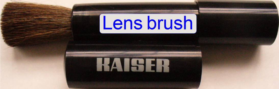
Lens
brush
To clean lens surfaces special lens
brushes can be used. The use of the lens brush for mirrors is not recommended.
The lens brush should be cleaned or replaced from time to time, because the
dust / lint will adhere to the hairs of the brush.

To protect optics from fingerprints during
execution of the cleaning procedure, finger coats are used; even so, used
materials will not be contaminated if they are touched. Latex gloves can also
be used but they are more expensive.
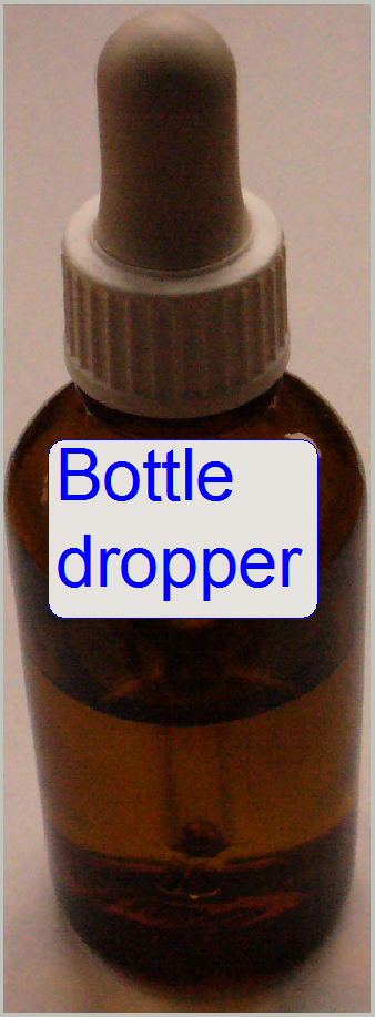 Bottle dropper
The liquid, used to clean optical
surfaces can be dosed excellent by a bottle dropper. The used liquid is 96% -
98% ethanol or methanol; available in any pharmacy, the bottle dropper also.
High concentrated ethanol or methanol is
very hygroscopic. After some drops of liquid is dropped onto the cleaning
material, close the bottle immediately, never leaf the bottle unclosed. To
avoid contamination of the cleaning liquid, the pipette should never touch the
material where the liquid is dropped on.
·
Take into account that such liquids are very flammable! The
quantity of the liquid in stock for such cleaning projects must not exceed 1l;
otherwise special fire prevention measures have to be taken!
Cotton
batting
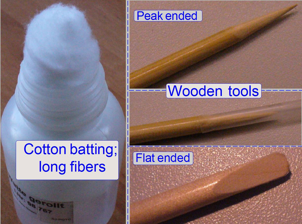
For some optical surfaces, like the
objective lenses, a very thin tool with cotton batting is used for the cleaning
procedure.
Wooden or bamboo tools
To reach the lens surface of the objective
on the tissue side, a peak ended wooden tool was created; to clean the lens
surface on the camera side a flat ended tool can be used.
· To create bamboo tools, Asian chopsticks
are very well suited as basic material.
 Lens cleaning tissue
Such lens cleaning tissues do not scratch
the optics surfaces; it can be used for mirrors and lenses both; nevertheless,
each surface of the tissue can be used for one wipe only!
Lens
cleaning pads

Because the size of one pad is large
(100x90 mm), and large pads are seldom needed, it can be cut in halves or
quarters.
These
pads are often used to remove dust from borders of the lens or edges of
mirrors. The surface of the pad can be used also for one wipe only.