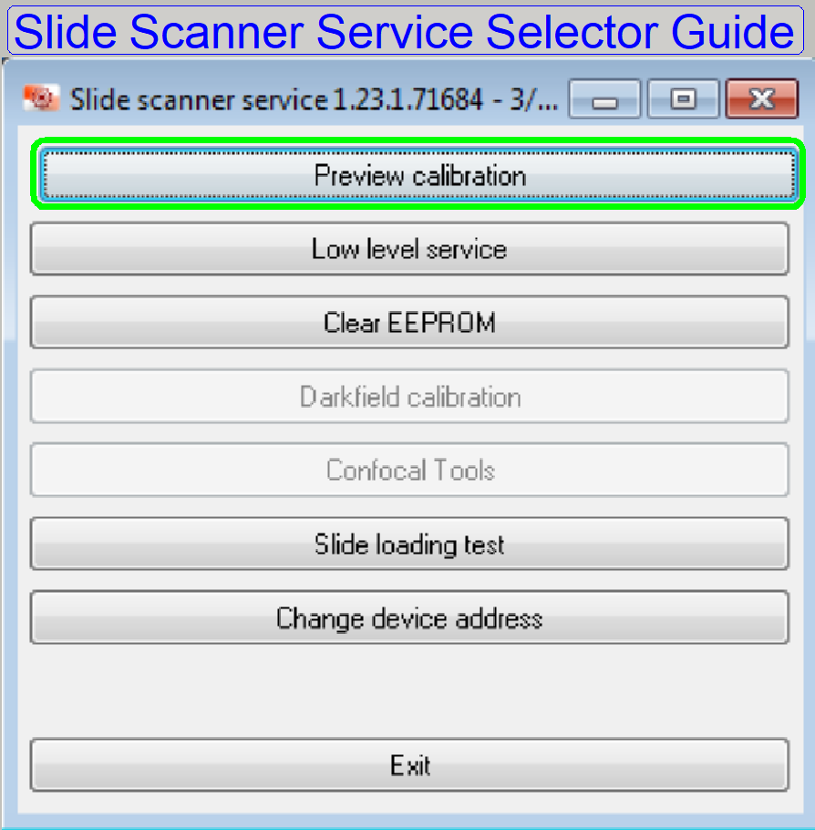
Preview calibration
procedure;
SMD_II
For technicians!
The newly developed scanners and components of
SMD_II requiring enhancements in the service program also.
While these developments,
the preview calibration procedure was also modified and this results in the new
preview calibration program.
Before starting the preview
calibration program following requirements and setups should be fulfilled and
should be finished:
General
·
Scanner type and
options defined (MicroscopeConfiguration.ini). Link S_II; M_II, D_II
·
Implemented
hardware units adjusted and defined. Link
S_II; M_II, D_II
·
Preview camera
defined (MicroscopeConfiguration.ini). Link S_II; M_II, D_II
·
Hardware limits
defined (MicroscopeConfiguration.ini). Link S_II; M_II, D_II
·
Scan camera
defined in (Microscope settings dialogue). Link
S_II; M_II, D_II
·
Implemented
objectives defined (Microscope settings dialogue). Link S_II; M_II, D_II
Scan BF image
path adjusted
·
Condenser
position adjusted Link
S_II; M_II, D_II
·
Chromatic
aberration adjusted Link
S_II; M_II, D_II
·
Stitching
adjusted Link
S_II; M_II, D_II
·
Camera rotation
angle adjusted Link
S_II; M_II, D_II
The scanner is able to scan
tissues in a high quality, only the preview quality is wrong.
The software asks the
service password: seristen
Select the
option: Preview calibration
Execute
following adjustments next
·
Preview
objective aperture set Link
S_II; M_II, D_II
·
Preview
objective focus adjusted Link
S_II; M_II, D_II
·
Preview camera
position and rotation angle adjusted. Link
S_II; M_II, D_II
1 Upper adjustment window
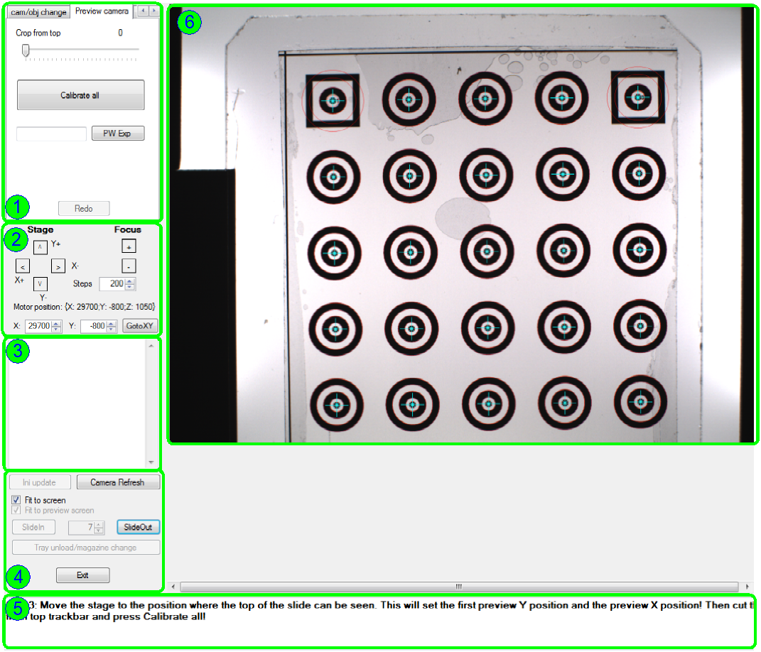
·
Commands for the
adjustments are shown here
6 Camera window
The camera window contains the image of the
·
Preview
camera or
·
the scan camera
depending on the step in progress.
3 Collected adjustment parameters
·
As the steps are
finished, defined parameters and values are shown and collected here.
4 Bottom adjustment window
·
Mainly common
commands for the adjustments.
5 Instruction window
·
Instructs the
operator (technician) what to do.
2 Stage movement and focus tools
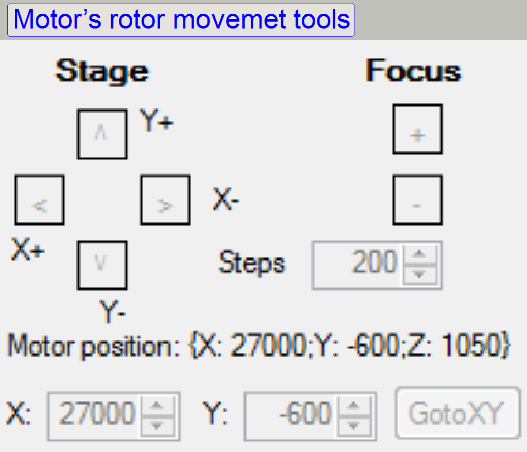
·
Move the
X-Y-stage to desired positions.
·
Set the focus of
the scan image during adjustments.
Steps: Type in a step number. The value is true for
the focus motor as well as the X-Y-movements.
- The step number may be changed any time, before moving the desired
unit.
If a known position should
be reached, you may type in a desired step number into the fields X: and Y:; then press GotoXY
Step 1 Camera and objective
Task
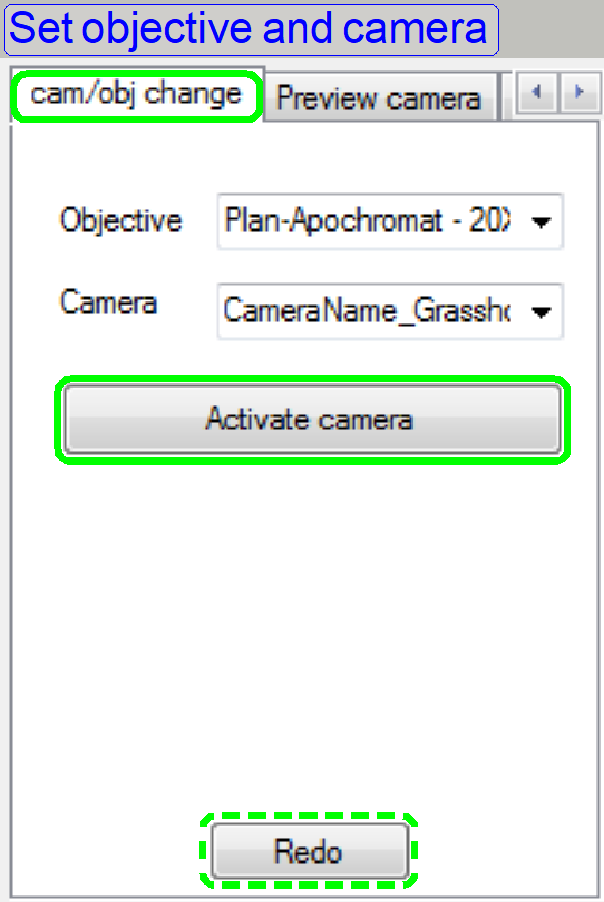 Please select camera and
objective.
Please select camera and
objective.
Objective: Select one of the installed objectives (20x
recommended).
Camera: Select the installed BF scan camera
(recommended).
1. Set and select the installed and used objective
magnification. The image path of the scanner will be set to the selected
magnification. With this magnification the preview calibration will be
executed.
2. Select the installed scan camera.
·
If the settings are correct, press “Activate camera”.
·
If there is any trouble with the camera, press “Redo”.
Step 2 Insert the preview calibration slide
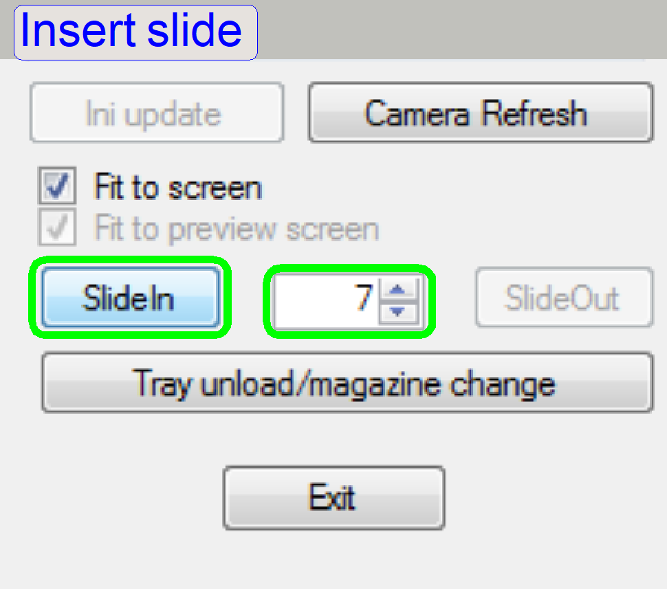 Task
Task
In the numerical field
select or type in the slide position of the Tray or the Magazine, in which the
single width calibration slide is found.
·
If the settings are correct, press “SlideIn”.
Step 3 Set Top X- and Y-position
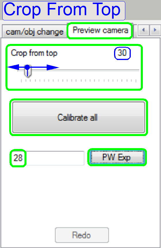 Task
Task
Move the stage to the
position where the top of the slide can be seen.
This will set the first
preview Y-position and the preview X-position!
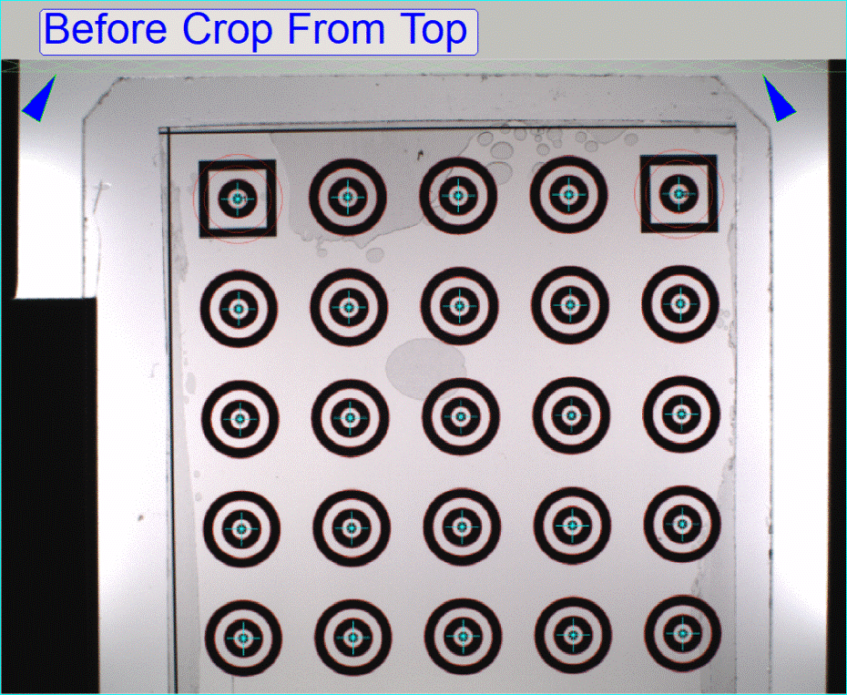
Then cut the part which
covers the top of the slide with crop from top track bar and press Calibrate
all!
Cut the part above the
slide. For this, move the bar.
Set the exposure time o the
camera.
·
Type in a value and press “PWExp”.
·
If the settings are correct, press “Calibrate all”.
Step 4 Barcode settings
Task
Please set the barcode
position and barcode area, then press “Set barcode params”.
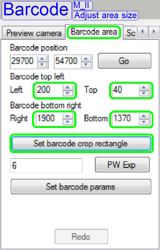
4a Barcode
area size
Adjust the size of the
barcode area so, that the barcode area of the slide is inside the shown
rectangle.
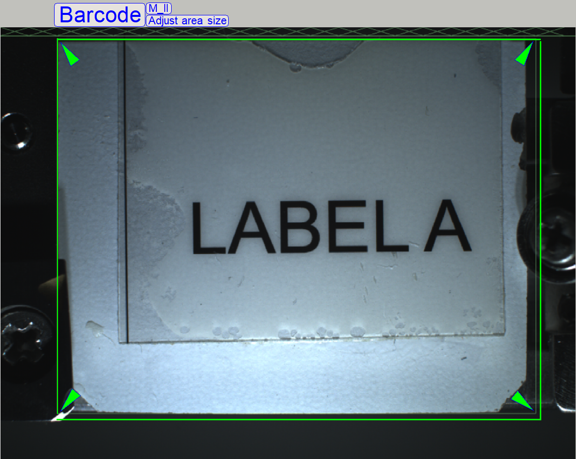 In the numerical
fields “Left”, “Top”, “Right” and “Bottom” type in numerical values to modify
the size of the rectangle.
In the numerical
fields “Left”, “Top”, “Right” and “Bottom” type in numerical values to modify
the size of the rectangle.
·
If the size of
the rectangle is correct, press “Set barcode crop rectangle”
Remark
Because the slide dimensions
of the calibration slide are not the maximal allowed dimensions, the values for
right and bottom should be defined a bit larger than the slide edge!
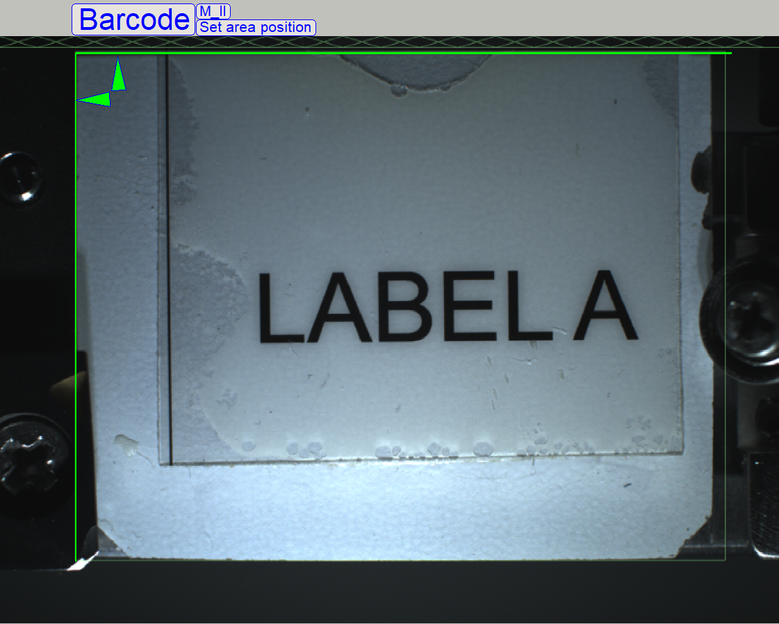
4b Barcode
area position
Sett the position of the
barcode area so, that the barcode area is in the center of the camera window.
4c Barcode
illumination
Adjust the position of the
barcode LEDs so, that the barcode area is illuminated evenly (bend the LEDs
carefully).
Type in a value for the
exposure time, then press “PWExp”
·
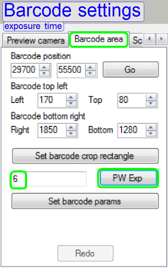 Repeat the step
until the brightness of the barcode rea is acceptable.
Repeat the step
until the brightness of the barcode rea is acceptable.
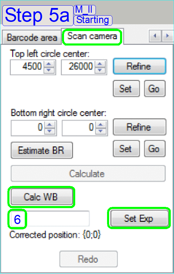
Step 5: Find circle centers
Task
Move the stage to the
position, where the top left circle’s center can be seen on the scan camera
image!
Then press Estimate BR!
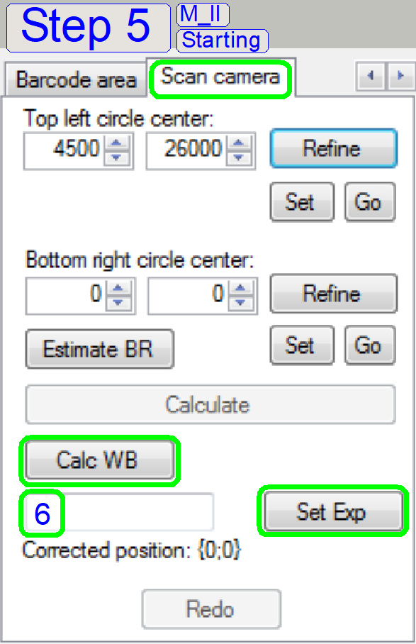

5a Set camera parameters
Because the scan camera is
used first time in the preview calibration process, camera parameters should be
set.
Exposure time
In the numerical field type
in a value (e.g. 6) and press “Set Exp”.
·
Repeat the step
until the brightness of the scan camera window is acceptable.
- White exposure time can be set any time if the button is available.
White Balance
·
Press the button
“Calc WB”.
- White balance can be calculated any time if the button is available.
Remark
As often as you press the
white balance, the color of the screen may be changed, because the RGB BF
illumination unit is used.
5b Find
the top left circle
 Move the stage in +X-direction first, and then use any movement button to
see the circle center in the camera window.
Move the stage in +X-direction first, and then use any movement button to
see the circle center in the camera window.
·
If parts of the
circle are visible, set a step size of 50steps and find the focus position of
the scan objective.
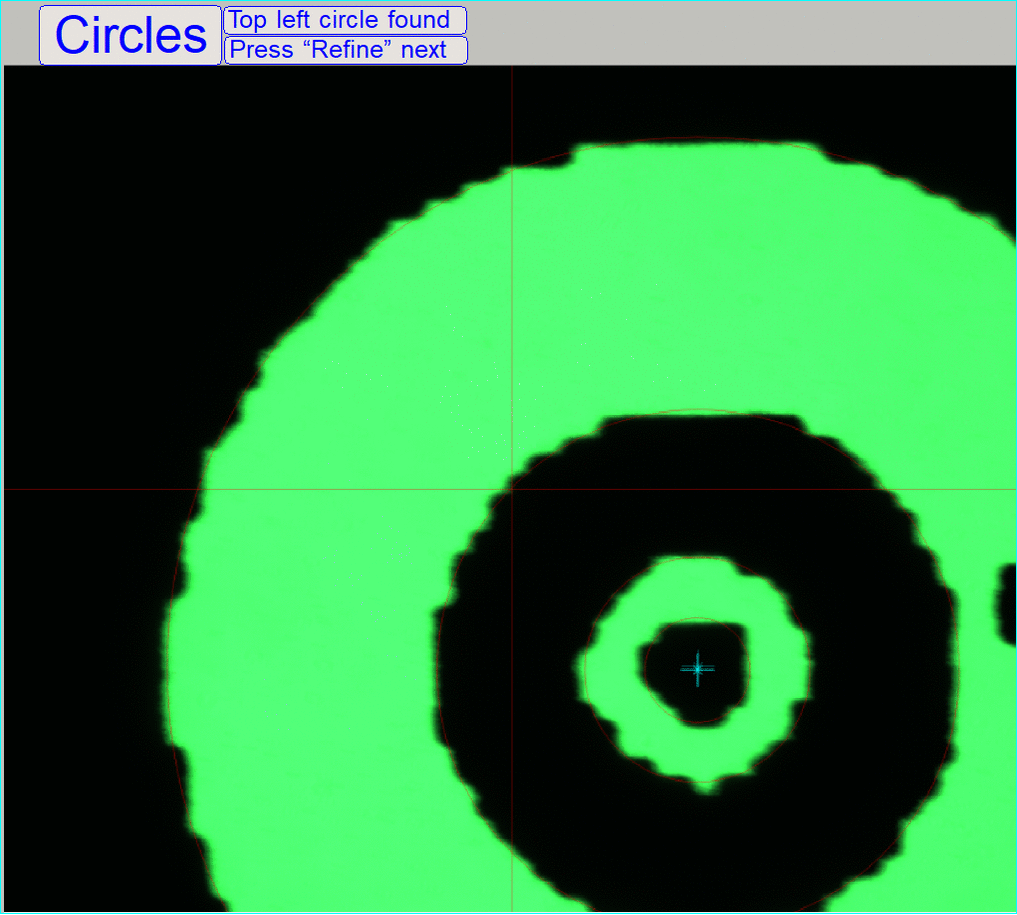
5c Refine top left circle center
The center of the circle is
shown in the center of the screen; the circle center meets the screen cross.
5d Estimate BR
The stage moves to the position of the Bottom
right circle.
If the center of the circle is not visible on
the screen, use the stage tools to find the circle center.
5e Refine bottom right circle
The center of the bottom
right center circle (4) is shown in the
center of the screen.
By pressing calculate,
Required positions are calculated and the preview camera’s position is fit to
the scan camera’s position.
If the calculation is
finished, the program goes to the step 6.
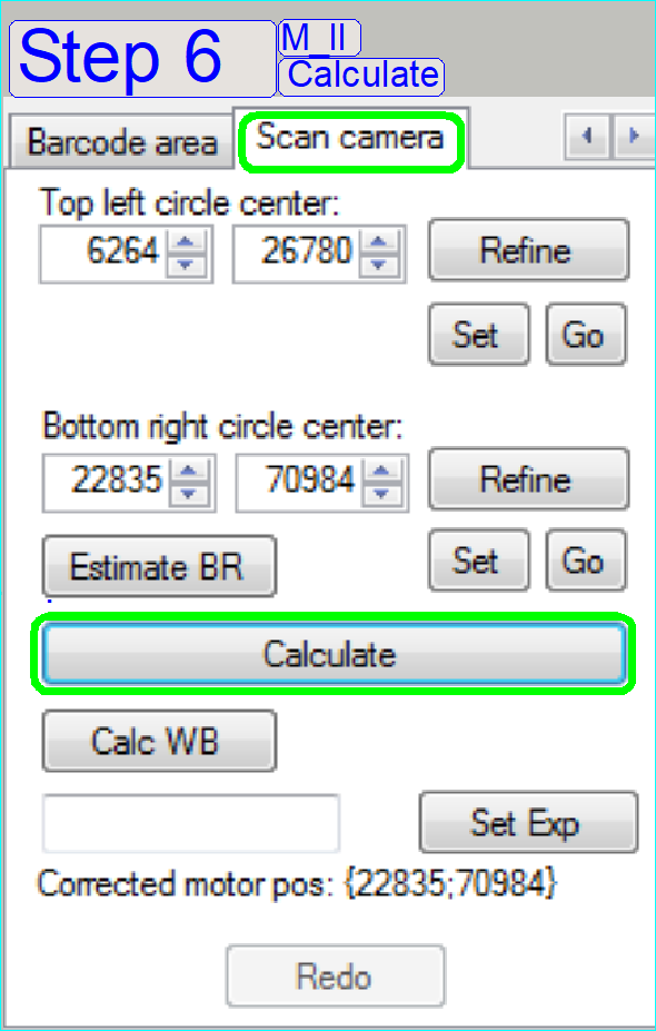
Step 6 Calculate circle centers
Task
Move the stage to the
position, where the bottom right circles center can be seen on the scan camera
image!
Then press calculate button.
Step 7 Check
result and finish
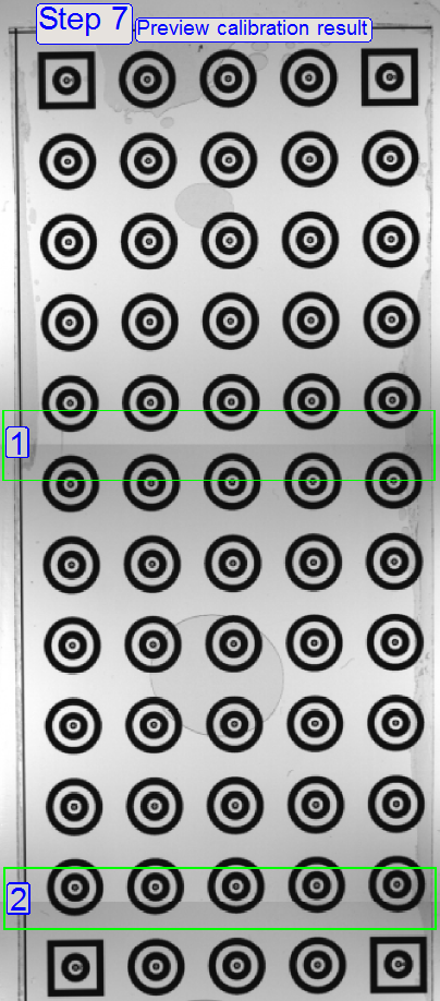
Task
The preview calibration has
been finished.
Now click on the full
preview image on the right side, then compare it with the scan camera image!
If they match, then press
Ini update button and remove slide!
Check the preview
calibration result!
Remember, the preview image
of the slide (the scan area) is made by 3 images of the preview camera and the
three images are stitched to each other.
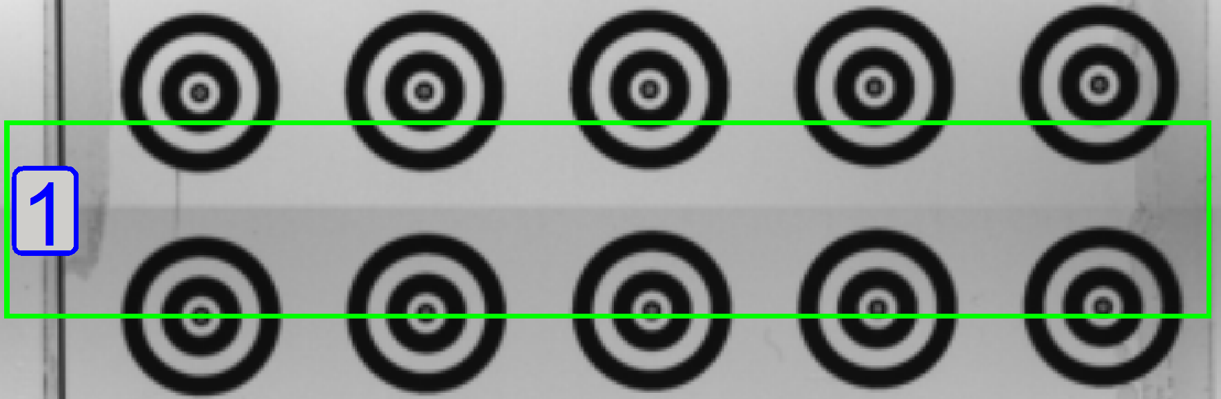 Now check the
stitching quality; result is shown on the right.
Now check the
stitching quality; result is shown on the right.
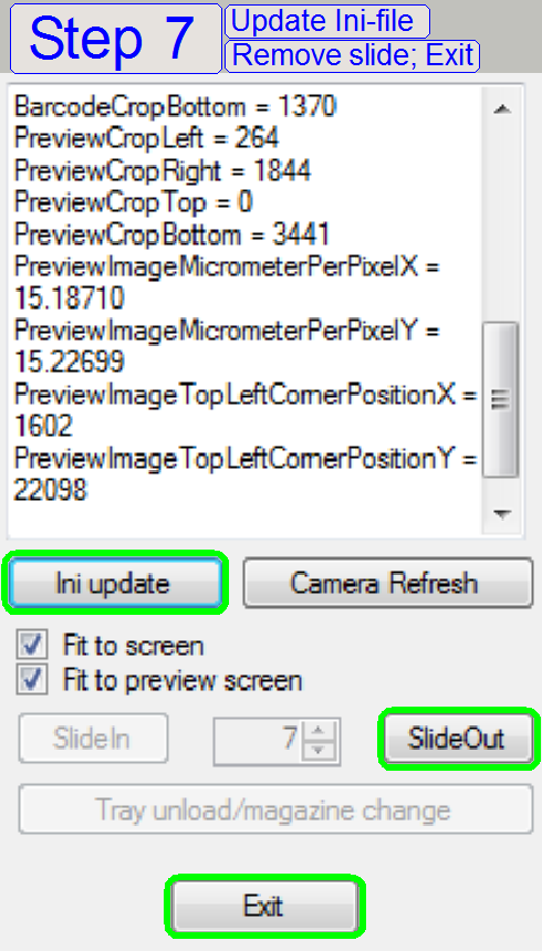
If the calibration result is acceptable,
save the ini parameters next
·
Press
"Ini update"
To finishing the calibration procedure, Press
·
SlideOut
and
·
Exit
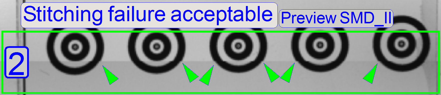
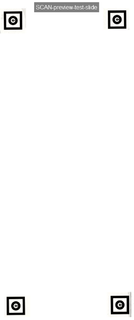
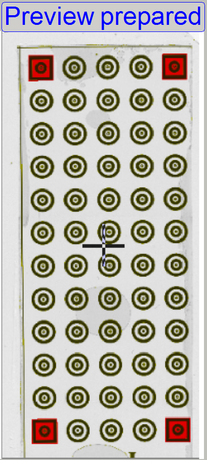 Scan the corner circles of the
calibration slide
Scan the corner circles of the
calibration slide
Start SlideScanner.exe and load the calibration slide.
Deselect unwanted circles from scanning.
Prepare the preview so, that only the corner circles are selected for
scanning, as shown.
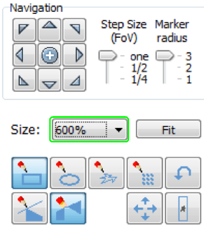
By enlarging the preview to 600%, the stitching quality can be checked.
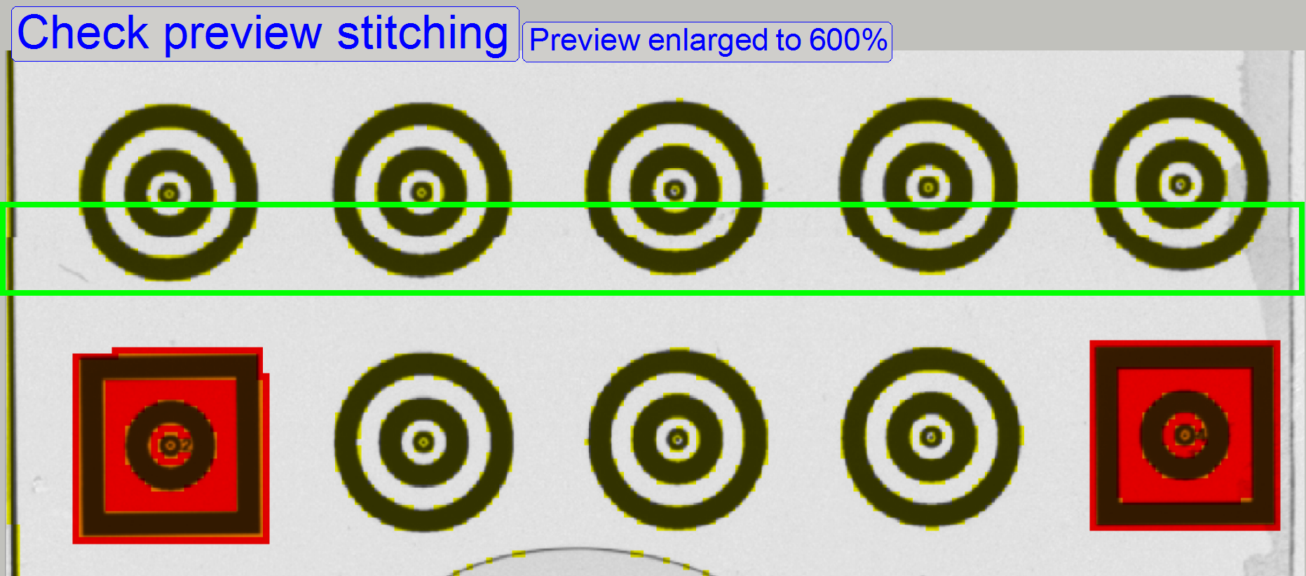
- The shown
stitching error is acceptable and do not need further adjustments.
 Prepare scan parameters
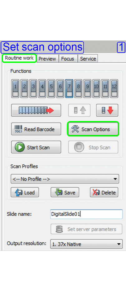
1 Routine work
- Open "Scan
options"
2 Scan option
- Set the
destination path for scanning
- Uncheck
Stitching
3 Set Preview options
- threshold to
100
- Set dilation
to 100
- Set speck
size to 0.5mm2
4 Routine work
- Type in a
file name
- Start scan
procedure.
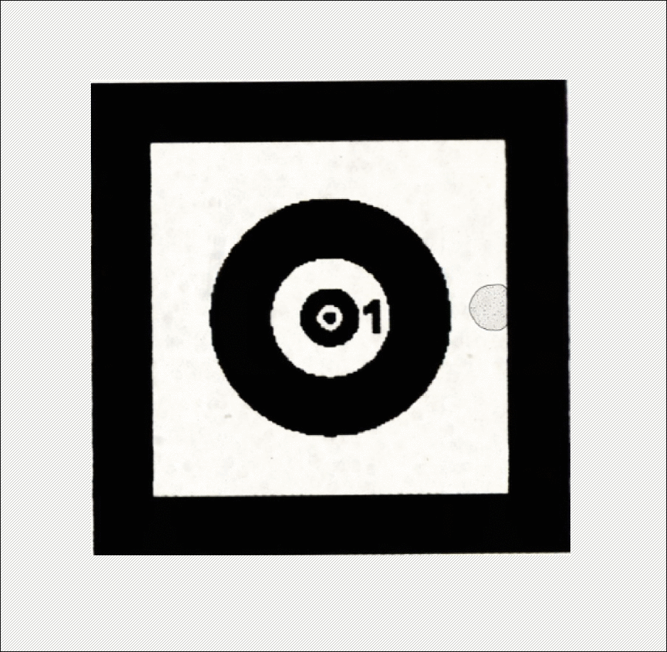
Scan result
By opening the scanned calibration slide with the slide viewer, the
scanned result can be checked.
Preview calibration finished
END