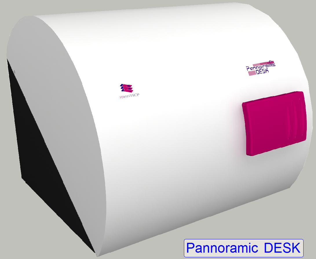
Housing, construction; D_II
For technicians!
.
This chapter handles components of the housing and mechanical
construction of the scanner DESK_II (D_II).
Enhancements
Following improvements are done in Pannoramic DESK
scanners, delivered since summer 2016
These modifications do not result in another scanner type, but to bundle
all the modifications, the term DESK_II was created and is used internally.
Scanners, delivered since summer 2016 including all the following
improvements and modifications, appropriate replaced units, used in previous
versions are no longer delivered in new scanners.
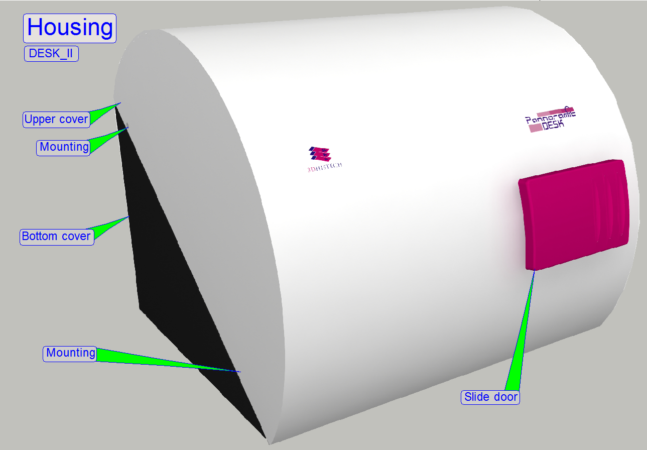
Housing
DESK_II's housing dimensions has changed, it is now nearly twice in
width
The slide door was modified, it is now enlarged to handle slides with
double width easily, the shift mechanics was modified.
The painting of the lower cover is black.
X-Y-Stage
Mounting
- Mounting of
the X-Y-stage unit to the scanner plate was modified, so vibration,
resonance and noise is reduced.
- The scanner plate
has a rectangular cut out for placing the X-Y stage unit's base plate into
it.
- The unit's
base plate is mounted to the bottom of the scanner plate with three
L-shaped holding elements and springs.
X-Y-Drive
- Using of
5-Phase stepper motors improves smoothness of the rotor’s movement to
reduce vibration and resonance.
- Newly
designed spindle mounting allowing simplified, easily adjustments and
exchange.
- Using an
integrated, slippage-free transport module (includes transport nut and
counter nut) simplifies adjustments.
- X-direction
prolonged to reach the double width of the slide.
X-Y-Rails
- Using of
improved X-rails and the modified distance
between the X-rails increases stability in X-direction.
- X-direction
prolonged to reach the double width of the slide.
- Newly
designed Y-rail solution increases stability in Y-direction.
Specimen holder
- Modifications
of the specimen holder allowing the movement of slides with a thickness of
1.2mm in the DESK_II.
- The DESK_II
can also hold slides of single width (25mm) by using a simple adapter or
double width (50mm); hereby the adapter is removed manually.
Focus unit
 Shutter mechanics removed
Because the scanner unit of the DESK is never able to scan slides in FL
scan mode, the mechanical shutter is also not required.
The ex-center of the focus unit may now rotate unlimited.
In DESK, the shutter unit was implemented for the Hardware limits and to
keep compatibility with SCAN and
Hardware limits not required
Because the shutter wire is removed, the rotation of the ex-center is no
longer limited. The ex-center may rotate unlimited.
Ex-center position visualization pin
In the position of the shutter arm of the ex-center, now only a
visualization pin is implemented to make the ex-center position adjustment
possible.
Stepper motor type exchanged
In the DESK, there was a 2-phase stepper motor with 200
full-steps/revolution used, so a resolution of the 3200micro-steps/revolution
is possible.
In the DESK_II a 5-phase stepper motor is implemented, this guarantees a
higher full-step resolution, and more
smooth movement of the rotor and so, vibration and noise are also reduced.
The revolution of the 5-phase motor's rotor after transforming is now
done in 6400µ-steps/revolution.
Increased slide thickness
The modified focusing solution allows now focusing of slides with a
thickness of 0.95mm to 1.20mm.
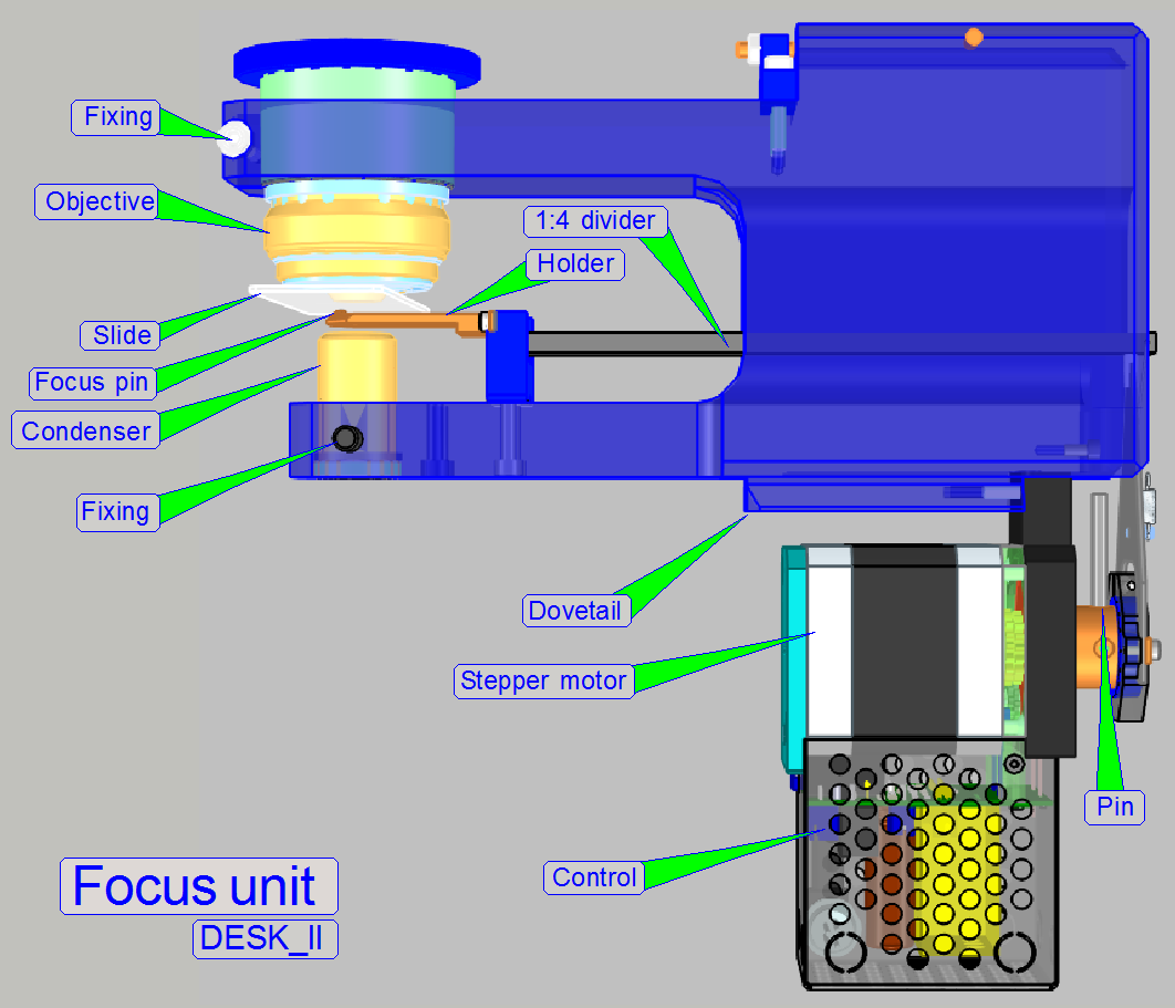
Modified focusing mechanics
To focusing slides with a thickness of 1.20mm, the movement range of the
focus pin had to be increased.
To reach this, the relation of the divider was modified to 1:4 and the
stepper motor's step angle was decreased.
The focus range is now 1600µ-steps, because the rotor's step size is now
reduced to the half, the rotor revolution is done in 6400µ-steps/ revolution.
Watch video: DESK II
Remove the lower housing
Mount the lower housing
Mount the upper housing
Slide door
The DESK housing consists of an upper and a lower housing; the upper
housing is mounted to the lower housing by four bolts, two from the left side
and two from the right side. The lower part of the upper housing is held by
clamps; these acting independently if the upper housing is shifted frontward.
If the mounting bolts for the upper housing are removed on both sides,
the DESK can be opened.
Watch video: DESK II Cover
1.
Remove the upper cover mounting bolts on both sides
2.
Pull the rear part
of the upper housing upward of about 5mm and
3.
 Shift the upper housing in direction to the front.
Watch video: Remove upper cover
4.
Remove the camera protector
as required.
5.
Rotate the DESK to the right and put it onto its right
side. Take care on the painting, do not scratch it!
6.
Loosen (or remove) the 3 mounting bolts of the lower
housing from the base plate.
7.
Rotate the DESK return onto the feet and shift the
entire lower housing backward.
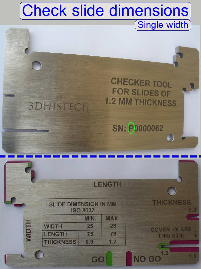
Allowed slide dimensions
 Single
width
Single
width
Length: 75.00 to
Width: 25.00 to
Thickness: 00.95 to
Double width
Length: 75.00 to
Width: 50.00 to
Thickness: 00.95 to
- If the first character of the serial number is an
“S” the tool is used to check the slide dimensions
of single width slides; thickness = 0.95 ... 1.05mm.
- If the first character of the serial number is a “P” the tool is used to check the
slide dimensions of single width slides; thickness = 0.95 ... 1.20mm.
- Please check the slide dimensions before
insertion of slides!
8.
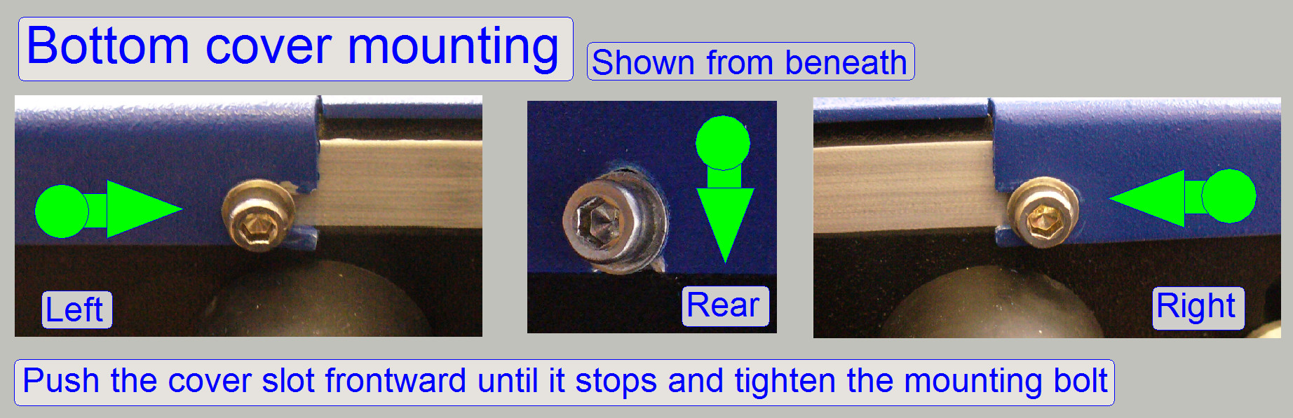 Shift the lower housing from the rear to the front so,
that the mounting slots of the lower housing are shifted between the base plate
and the washers of the mounting bolts.
Shift the lower housing from the rear to the front so,
that the mounting slots of the lower housing are shifted between the base plate
and the washers of the mounting bolts.
9.
Rotate the DESK to the right and put it onto its right
side. Take care on the painting, do not scratch it!
10.
Press the rear part of the lower housing against the
base plate so, that there is only a very small or no gap and tighten the fixing
bolt on the front left side.
11.
Rotate the DESK
to the left and put it onto its left side. Take care on the painting, do not
scratch it!
12.
Now press the right part of the lower housing to the
front and tighten the appropriate mounting bolt in the front.
13.
Finally, tighten the mounting bolt on the rear.
14.
Put the DESK return onto the feet and mount the upper
housing.
15.
Insert the lower fixings into the appropriate slots of
the lower housing and push the upper housing in direction of the rear.
16.
Fit the rear part of the upper housing with the upper
part of the lower housing and drive in the mounting bolts from the left and right
side.
Watch video: Mount upper cover
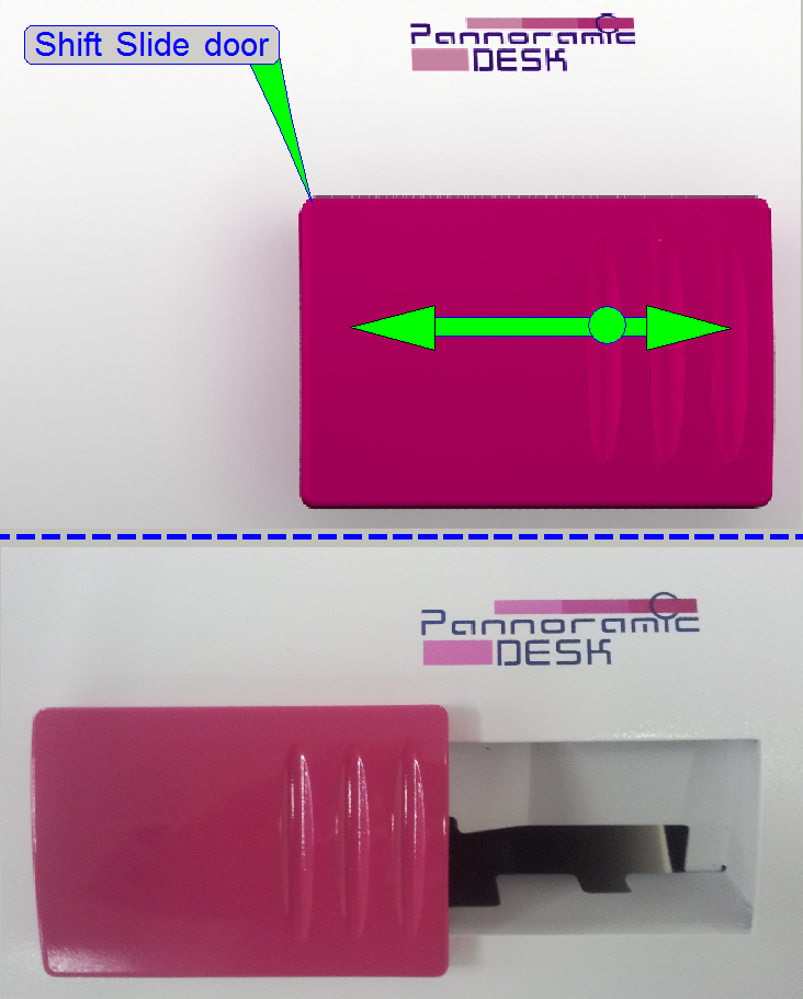
The mechanical construction
of the slide door allows the shift of the door to the left or to the right
respectively. Please shift the door to the left to open the door and shift the
door to the right to close the door.
If the slide door is opened during the scan process is in progress, the
scan process will be stopped until the door is closed again; to avoid finger
squeezing.
Important
Please do not pull the door
to open the door!
Watch video: “Open and close the slide door”
 Since the software version 1.15, the scanner units are
configured in the “MicroscopeConfiguration.ini” file, in the section
[Microscope].
Since the software version 1.15, the scanner units are
configured in the “MicroscopeConfiguration.ini” file, in the section
[Microscope].
[Microscope]
SerialNumber = PDESK-02xxxxxx
MicroscopeType
= 3DMic12
ScanCameraType = ;value is
unimportant
PreviewCameraType
= CVrmc_m8_pPro_Double
BarcodeReaderType = PreviewCamera
LoaderType
= SL_1Slide_DoubleWide
CameraChangerType = CC_None
ReflectorTurretType = RT_None
BrightfieldLightSourceType
= RGBLedLight
ObjectiveChangerType =
OC_None
ObjectGuideXYZType
= OGXYZ_TypeDouble
FlashUnitType = NoFlashUnit
NDFilterType = ND_None
PreviewLightType =
PreviewLightUnitType_Type3
 PowerSwitchBoardType
= PowerSwitchBoard_None
PowerSwitchBoardType
= PowerSwitchBoard_None
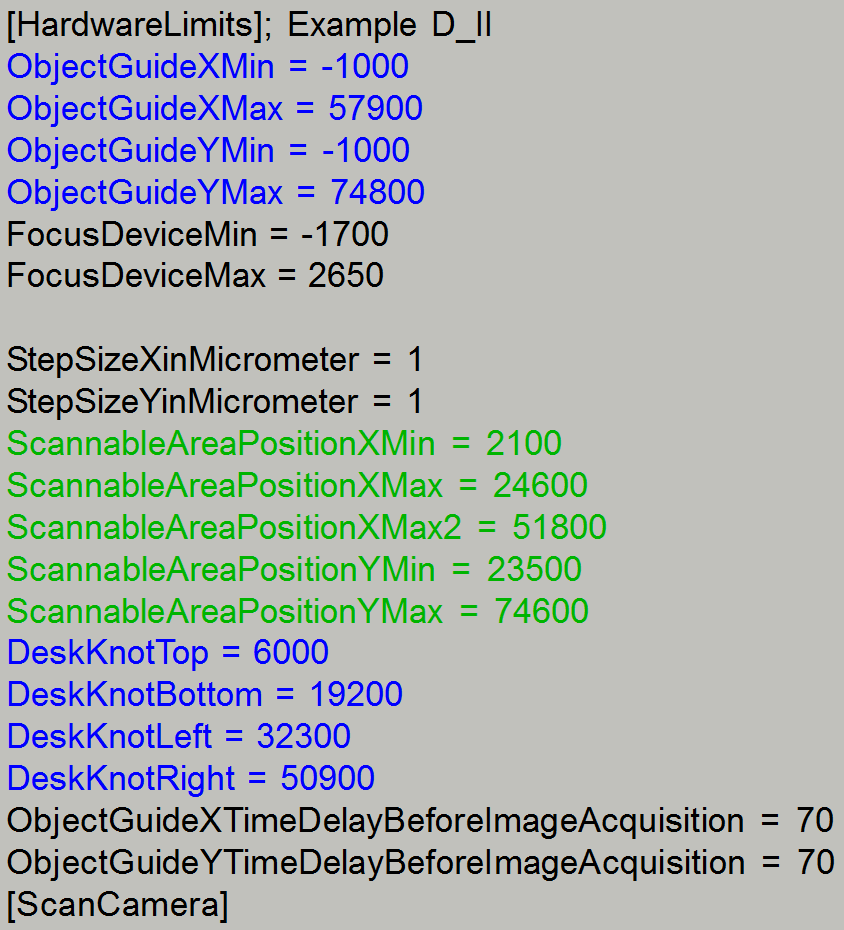
[HardwareLimits]
For more information about the parameters, used since software version
1.15, see the chapter INI-Files and the section
[Microscope].
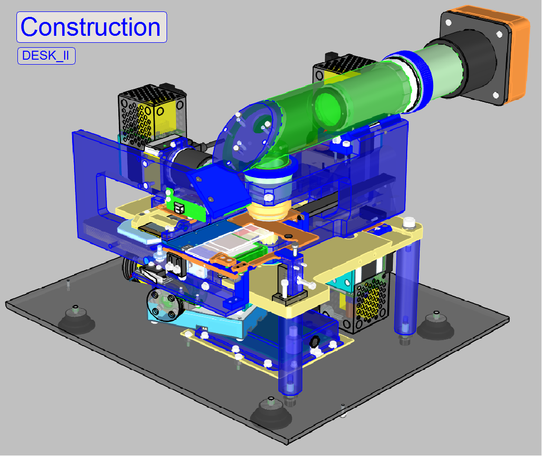
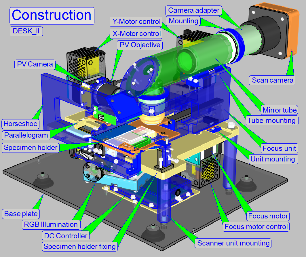 The mechanical construction of the DESK includes a
base plate and the scanner plate only. In this chapter components are shown and
adjustments are described.
The mechanical construction of the DESK includes a
base plate and the scanner plate only. In this chapter components are shown and
adjustments are described.
Adjust
the scanner plate position
Adjust the
door switch position
Adjust the
specimen holder fixing
Watch video: D_II_Construction
· For
safety regulations regarding human health and scanner functionality please
refer to: Precautions
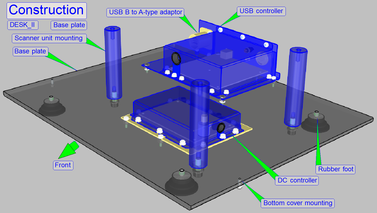
The base plate contains the USB- and
the DC-electronics box.
The scanner unit mounting is realized with three distance peaces.
·
The scanner plate is mounted to the distance peaces
with 5mm hexagon key bolts from the top.
·
Position of the scanner plate is adjustable.
In the DESK, like in the
The mounted main units of the scanner plate are:
- Focus unit
- X-Y-stage unit
- Preview and barcode
unit (the horseshoe)
- Brightfield RGB
illumination
- Image
path of the DESK is mounted onto the focus unit by using a mirror tube;
this is mounted by using a dovetail foot.
Watch video: Dismount
units
Mount
units
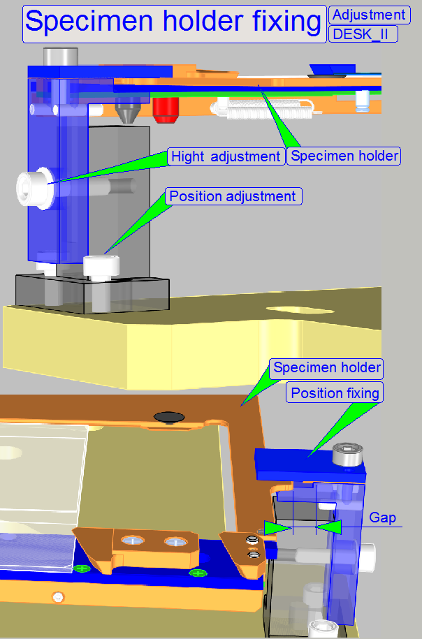
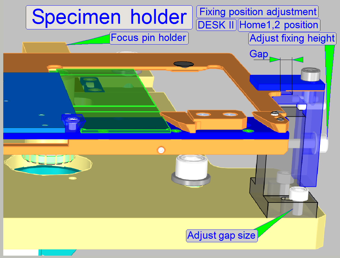
Specimen holder fixing
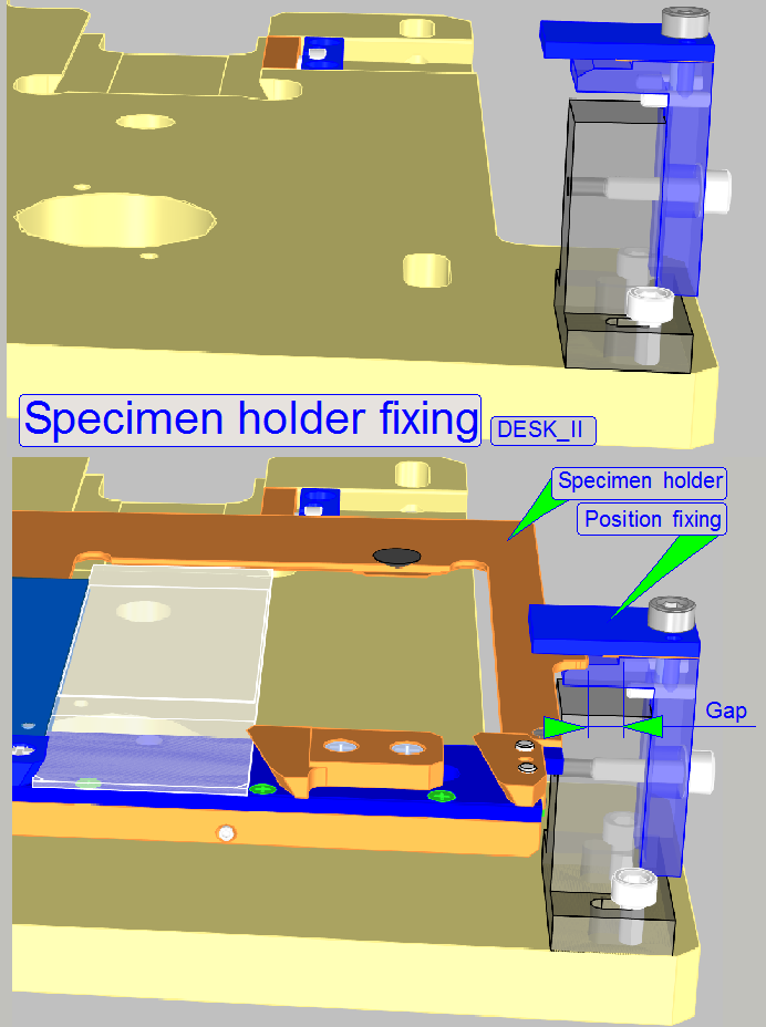 Because the slide
is inserted or removed manually into the DESK, the specimen holder must
be fixed during these actions.
Because the slide
is inserted or removed manually into the DESK, the specimen holder must
be fixed during these actions.
If the specimen holder is in the Home1,2 position or anywhere in
direction to the negative limits, the slide action can be done. In this
position, the specimen holder is fixed on the right side and supported by the
specimen holder supporter on the left side. With this solution, the slide
insert or remove action can be done safely, without bending the specimen holder
or the parallelogram.
The right hand supporter of the specimen holder fixing contains
chamfered edges in –X- and –Y-direction, so the specimen holder fixing guide
will not jam if the specimen holder is moved in negative direction.
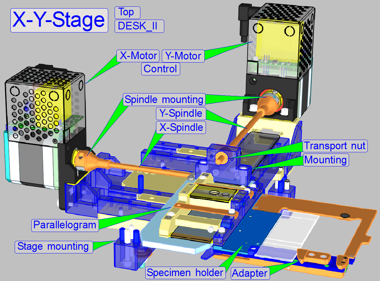
Drive
The X-Y-Stage unit is used to move the slide into the appropriate
positions during slide insertion and remove, during the preview creation
process and barcode capturing to the positions of the preview camera's field of
view and during the specimen scan process, the slide is moved continuously to
capture the Field Of Views for the scan camera.
To reach the required movements, a spindle driven mechanics is used in
both directions, so a resolution of 1µm/rotor step is realized.
The spindles are driven by a 5-phase stepper motor with a transformed
resolution of 3200µ steps/revolution, so a distance of 3.2mm movement is done
after 1 revolution of the rotor.
Parallelogram
The parallelogram allows shifting of the slide (and so the specimen) in
Z-direction during focusing, the movement is possible over the entire focus
range (and a bit more). By using a parallelogram, an inclination of the
specimen during focusing is avoided.
Specimen holder
Newly designed specimen holder mechanics allows the insertion and
scanning of single width and double width slides with a thickness of up to
1.20mm.
By using a removable single width adapter, the software knows whether a
single width slide (adapter present) or a double width slide (adapter removed)
should be scanned.
The adapter is inserted or removed manually by the user.
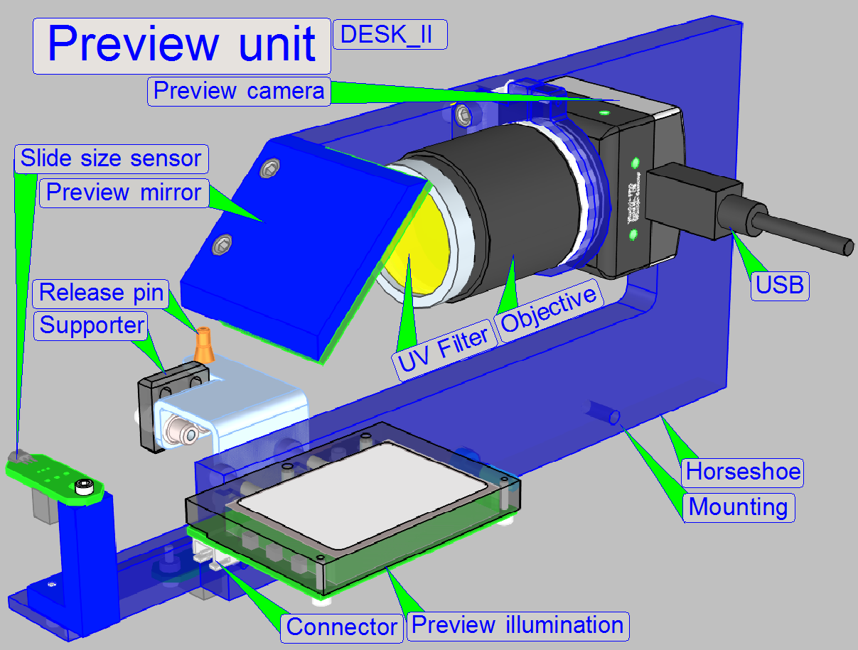
The preview unit creates the preview of the slide, so the user knows the
position of the sample on the slide and may select the tissue for scanning or
only parts of interest.
Single width slides
If single width slides are inserted, the entire preview of the scan area
is made by 3 images of the camera, the fourth image is the barcode area.
The 3 images are assembled by software to the preview, shown in the
preview window of slidescanner.exe.
Double width slides
Because the slide width is doubled, the preview creation process is also
doubled.
The preview camera makes 6 images of the slide's scan area and assembles
these to the preview, shown in the preview window of SlideScanner.exe
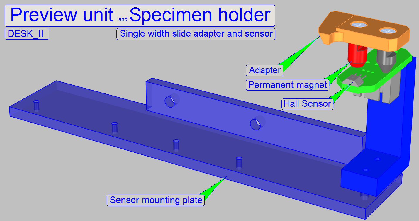 Single width slide adapter and sensor
As mentioned above, the specimen holder may hold slides with single
width and double width.
If single width slides should be inserted into the specimen holder an
adapter is used.
To tell the software, that the adapter is present, a Hall sensor,
mounted on the preview unit's sensor mounting plate is used.
If the sensor shows the active state in the slide insert position, the
adapter is present, slides with single width will be inserted.
Adjustment
Move the X-Y-stage with the service program to the slide insert position
and insert and remove the adapter more times. During these actions, the
presence or absence of the adapter have to be surely and correctly.
- Check this
behavior more times.
If checks failed, adjust the sensor position more precise
Physically, the focus
position is defined by the distance of the objective to the tissue. If the
tissue is in the focus of the objective, a sharp image is seen by the camera.
Because the tissues are different from each other in thickness, and the
thickness can change inside the same tissue also, the focus position must be
checked and corrected always, during the scan procedure.
- In Pannoramic scanners, as well as in the
DESK_II, the real focus position is found by moving the slide toward or
away from the objective via the focus pin.
- The focus position is influenced by both,
the fixed (adjustable) objective position and the actual position of the
focus pin.
Furthermore, if the slide as
well as the objective will be changed, the specimen holder must be moved away
from the objective to avoid collision.
Watch video: RGB BF Illumination unit
Monochrome cameras requiring monochrome illumination.
The construction of the BF optical path uses only a monochrome camera,
so only monochrome images can be produced.
To create color information of the tissue with a monochrome camera, we
illuminate the tissue with monochrome light.
If the tissue is illuminated by blue light, and we are making an image
of the Field of view, the gray scaled camera image contains the intensity of the
blue parts in the tissue.
Because the pixel resolution of the camera is very high and the
resolution of the image's gray scale is 10bit per pixel (or higher), very
detailed information of the blue part in the FOV related to the appropriate
pixel can be reached.
If we repeating the procedure with the colors Green and Red, 3 images of
the same FOV are produced and so, the software knows detailed color information
about each pixel of the Field Of View.
By using the software coloring method the true color information of each
pixel is found.
By using cameras with a large image sensor low shutter time and high
pixel resolution (small pixel size), the scan time of the tissue can be held in
acceptable boundaries and the result is an image with high resolution and high
color fidelity.
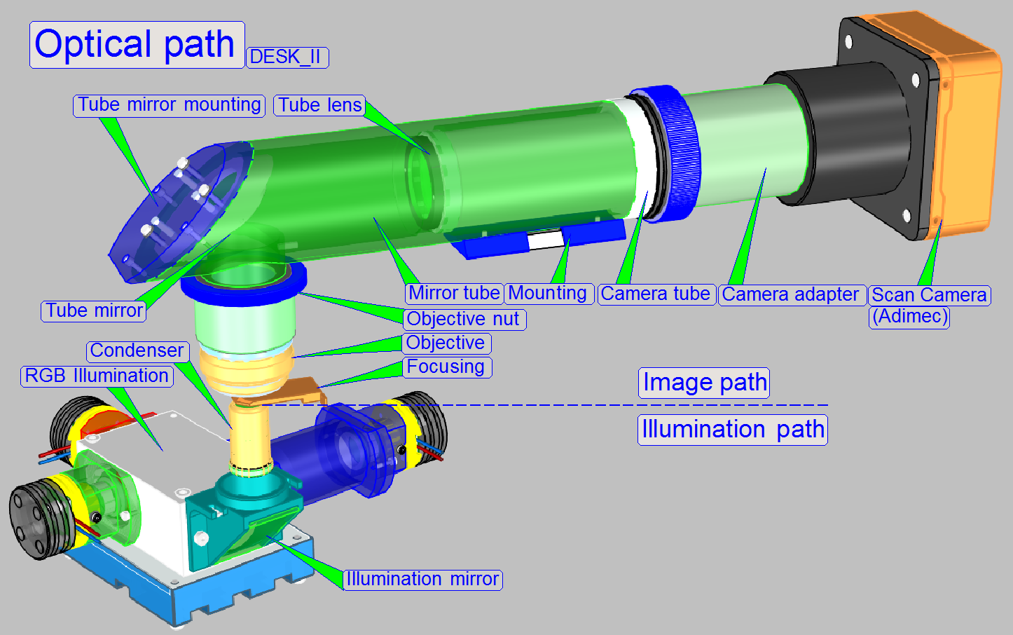
The optical path can be devided principially into an
illumination part and an image part.
The border between both is the specimen.
The bottom of the specimen is illuminated, while the
top of the specimen emits the image.
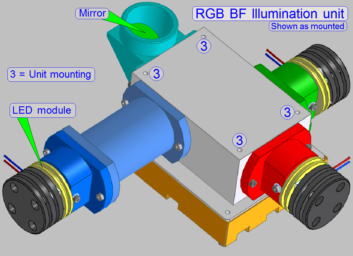
Illumination
In the DESK_II the specimen's illumination is done by
an RGB illumination unit, an illumination mirror and the condenser.
The RGB illumination unit creates monochrome light in
the wavelength of Red, Green and Blue, sequentially, so, the specimen's Field
of View is three times illuminated.
The control of the illumination is mainly done by the
shutter time of the camera (triggering), the timing may be done hardware or
software controlled.
The created monochrome, parallel wavelengths are reflected by the illumination
mirror in an angle of 90° to the condenser and this focuses the lightrays to
the field of view, observed by the Objective.
Image
The Quality of the image is mainly influenced by its size, resolution,
brightness and contrast.
Size and resolution is influenced by the camera adapter and the sensor
parameters of the scan camera, while other image parameters are mainly
influenced by the construction of the image path, the image illumination and
image magnification.
The objective gathers the light rays, passed through the image and
arranges these, together with the tube lens to an image.
The size and resolution of the image may be varied in limits by the
magnification of the camera adapter.
 If the limit in –X-direction is reached, a small gap of
about 0.1mm should exist, so jam may not occur in –X-direction.
If the limit in –X-direction is reached, a small gap of
about 0.1mm should exist, so jam may not occur in –X-direction.
Adjust the scanner
plate position
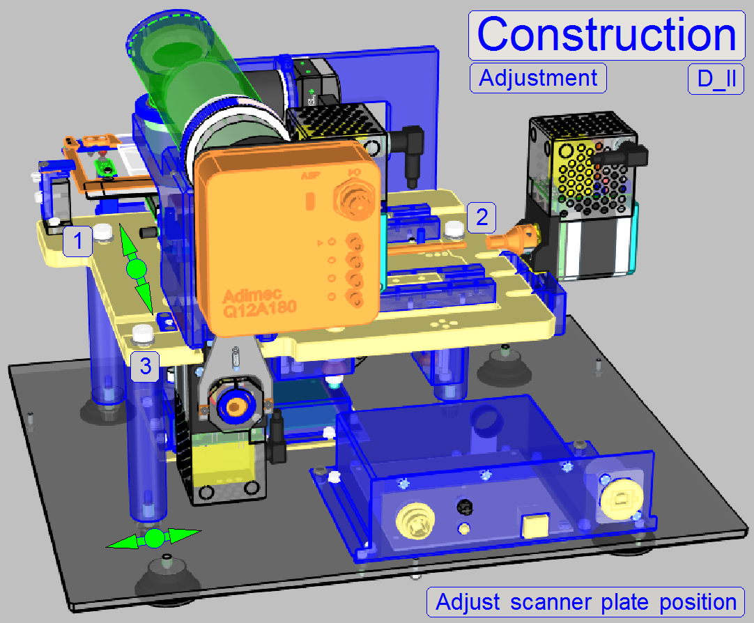 To ensure, that the scanner plate and any internal part
do not touch the housing, its position can be adjusted.
To ensure, that the scanner plate and any internal part
do not touch the housing, its position can be adjusted.
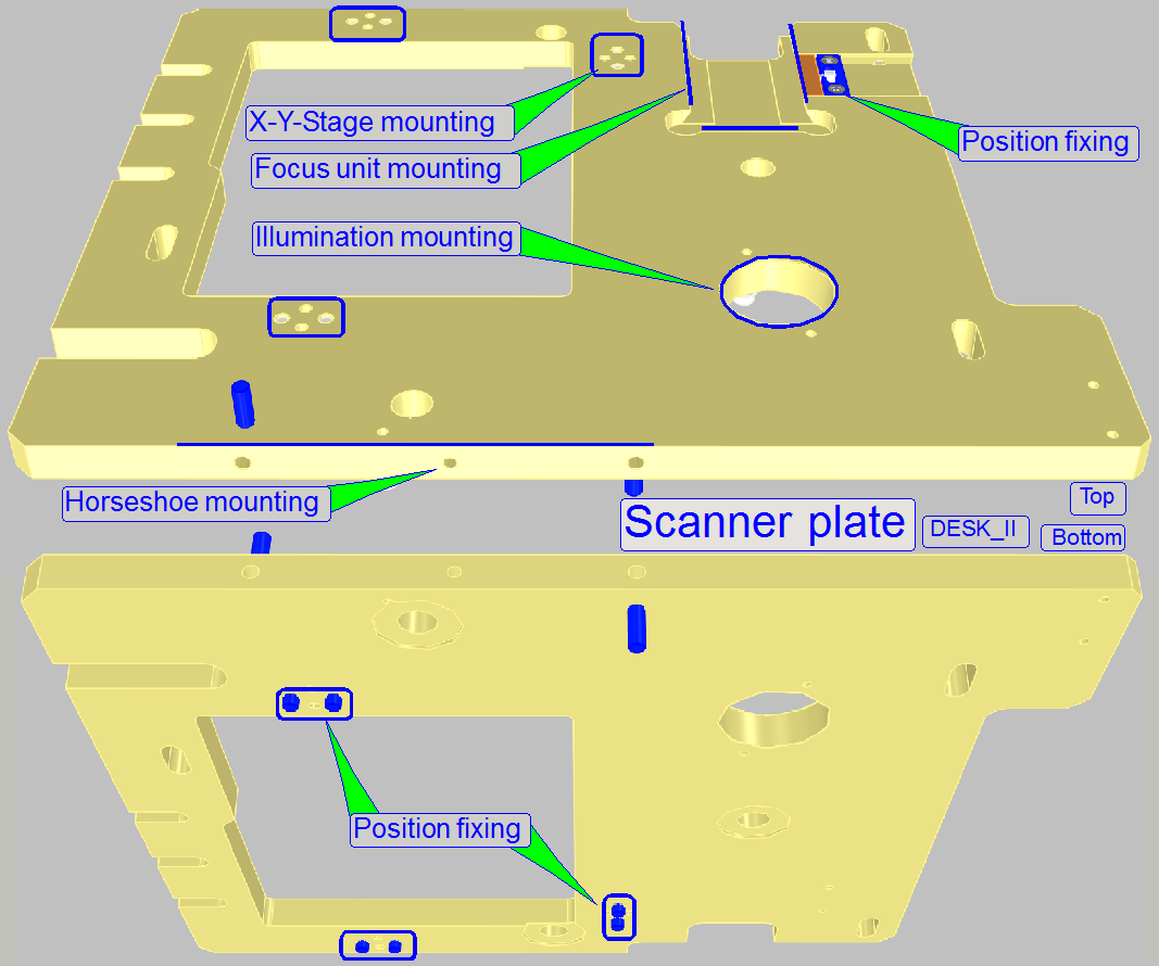
The mounting of the scanner plate consists of 3pillars, mounted to the
base plate from beneath, the scanner plate is mounted with the bolts 1,2 and 3
to the pillars.
The long holes in the base plate allow a positioning of the scanner
plate in the mathematical X-direction and the long holes in the scanner plate
allow the positioning in Y-direction.
·
Mount the lower housing (see above “To mount the
lower housing”).
·
Adjust the position of the scanner plate so; that no
internal part touches parts of the correctly mounted lower housing.
·
Especially, check the distance of the focus plate and 4:1
divider of the focus unit in relation to
the rear part of the lower housing, no part of the focus unit should touch the
back wall; a gap of about 0.5 ...1 mm is required (adjust the
Y-position)!
·
Fit the upper housing, open the slide door and check
the gap between specimen holder and right side of the housing, if the specimen
holder is in the negative limits; there should be a gap of about
·
Furthermore, check the position of the mirror tube; it
should be nearly in the middle of the housing opening.
·
If the scanner plate position was modified or adjusted
the following adjustments have to be done or checked:
o
The door sensor acting position (see “The door closed
position” and “To adjust the
door sensor position”
o
The specimen holder fixing position (see “Adjust the specimen
holder fixing”)
o
Adjust the supporter position (see “Adjust the supporter
position on the left side of the specimen holder”)
The door sensor should signal the “door closed” state safely, if the
door is closed; therefore the door sensor should acting about 1 ...
Adjust the door switch position
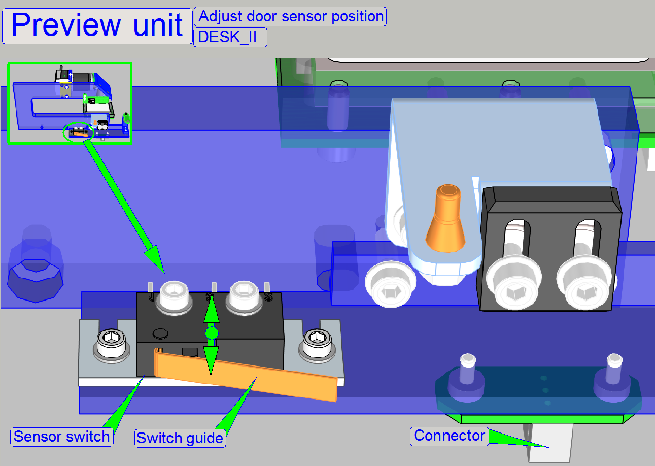
This adjustment should be done only, if there are problems with
recognizing of the “door closed” state, e.g. if the scan process is interrupted
without any interpretable reason; if the mountings or adjustment bolts was
loosened or the position of the scanner plate was adjusted or modified.
This adjustment assumes that the scanner plate position is correct, see
above “Adjust the scanner plate position”.
1.
Remove the upper cover (see above).
2.
Loosen the mounting or adjustment bolts.
3.
Move the switch to the front or to the rear as desired
and tighten the fixing bolts.
4.
Fit the upper cover as required for the normal work,
but do not drive in the cover mounting bolts.
5.
Check the “door closed”
position with the service program.
6.
Repeat from step 1 until the door closes correctly.
7.
Check this adjustment again if the upper cover is
fixed with the bolts.
 Adjust the
specimen holder fixing
Adjust the
specimen holder fixing
This adjustment assumes that the scanner
plate position is correct, see above “Adjust the scanner plate position”.
- During these adjustment, the
parallelogram must not be strained!
Position
adjustment
1.
Loosen the bolts of "Adjust gap size"
2.
Set the X-Y-stage to the limits Y-min and X-min, (see
also “The X-Y-stage” and “Find the hardware limits for the
X-Y-carriage”).
3.
Position the entire specimen holder fixing so, that
the fixing guide of the specimen holder has a gap of about 0.1mm in the
hardware limit positions X-min and Y-min.
Adjust
the height
4.
Set the X-Y-stage to X-Home1,2 and Y-Home1,2.
5.
Insert a slide.
6.
Loosen the bolt "Adjust fixing height".
7.
Set the focus position to +1300 steps (SW position =
2650).
8.
Fit the height of the specimen holder fixing to the
specimen holder guide and tighten the fixing. To reach this, move the X-Y-Stage
in
Adjust the supporter
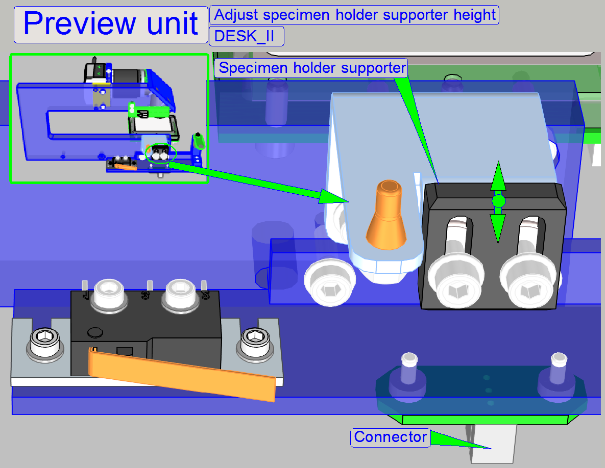
This adjustment assumes that the specimen holder fixing position on the right
side is already adjusted.
9.
Loosen the supporter fixing bolts.
10. Set the X-Y-stage
to X-Home1,2 and Y-Home1,2.
11. Move the supporter
downward, then upward until the supporter part of the specimen holder is
reached; there should be no pressure against the specimen holder.
12. Tighten the
supporter fixing bolts.
Define the slide insert and remove parameters
The following parameter values defining the slide
insert and remove position for the specimen holder in the DESK. The values are
often 0, it means Home1,2; the values for the parameters “InsertSlide PositionX“, “RemoveSlide PositionX1“, and
“RemoveSlidePositionX2“ can be used to
adjust the specimen holder position to the housing, but the size of the gap is
not critical.
If any value would be more the 1000 steps, the scanner
plate position must be corrected (see above “Adjust the scanner plate
position”).
Relevant
parameters in the file “MicroscopeConfiguration.ini”
The shown values are for information only!
[SlideLoading]
InsertSlidePositionX=200
InsertSlidePositionY1=0
InsertSlidePositionY2=0
InsertSlidePositionY3=0
RemoveSlidePositionX1=200
RemoveSlidePositionX2=200
RemoveSlidePositionY=0