USB and DC control;
D_II
For technicians and partly for sales managers!
The following description handles the electronics and electrical
components and cabling, used in the Pannoramic scanner DESK_II.
Contents
Important remark
·
After maintenance or
services and performed tests of the scanner are 100% finished, protective
ground connections and other safety regulations related to hazardous voltages,
accessible conductive parts and dangerous to life parts have to be checked
(again).
·
For safety regulations regarding
human health and scanner functionality please refer to: Precautions

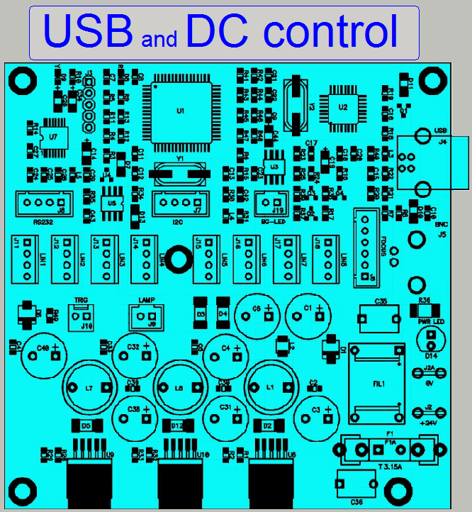
The connected power supply
MPU 100-108 with an input
voltage range of 100V~ to 240V~ AC and an output voltage of 24V- DC
supplies the motors and other internal units with power. Inside the
USB-controller, the DC-controller as well as in the stepper motor electronics a
local power supply is located and these create further, required voltages.
·
The power switch can also be used to switch off the
entire scanner if mechanical jamming or any other emergency situation occurs!
Important
230V~
or 100V~
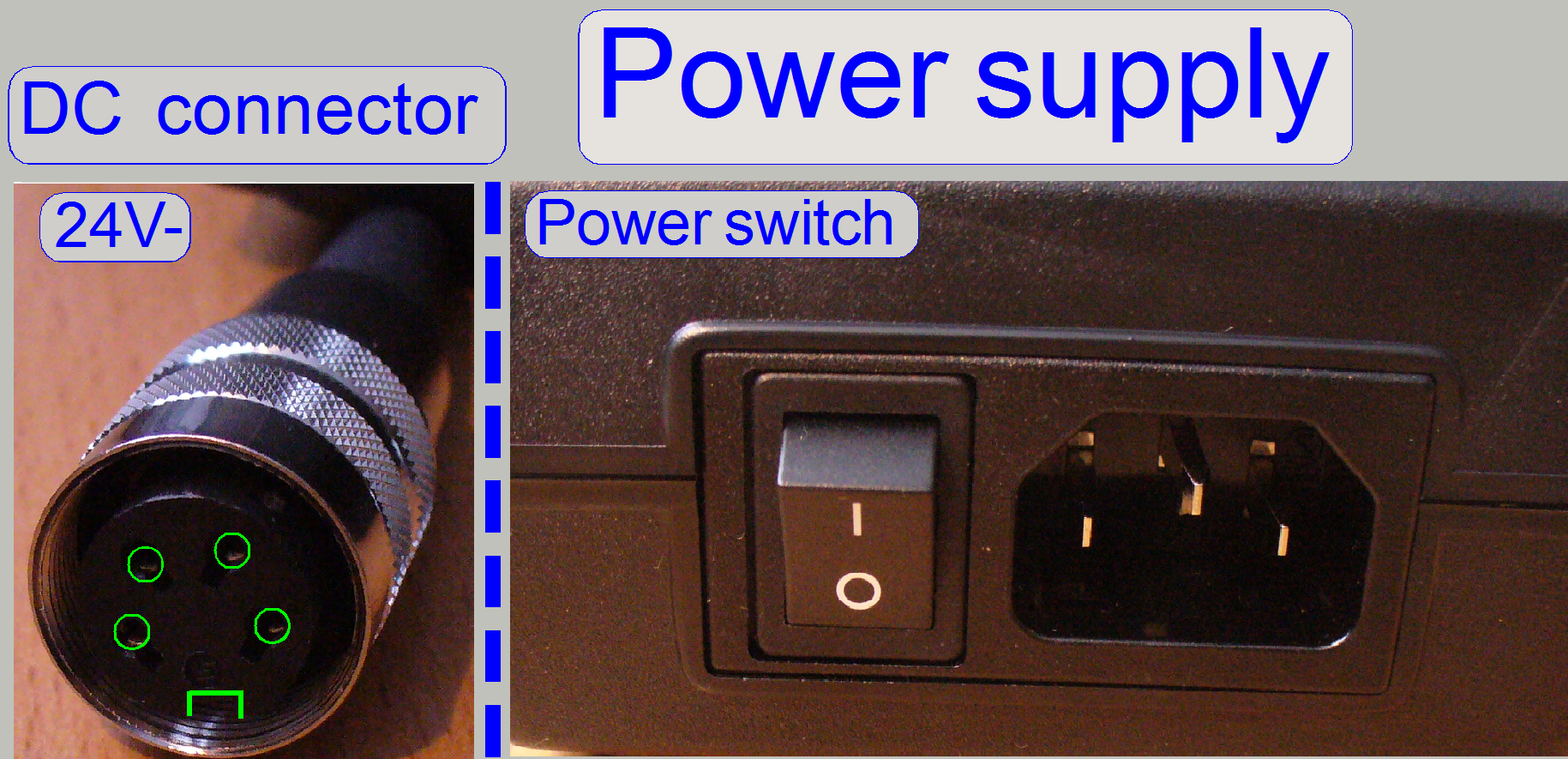
The alteration of the mains power input in the range from 100V~ to 240V~
is reduced to the use of the appropriate mains power cable!
If the mains power is changed from 230V~ to 100V~ or vice versa, no
alterations are required inside the scanner; the change of the mains power is
fully handled by the input voltage range of the power supply.
USB Controller
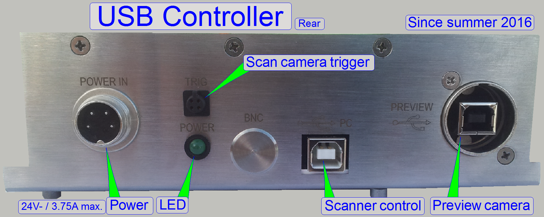
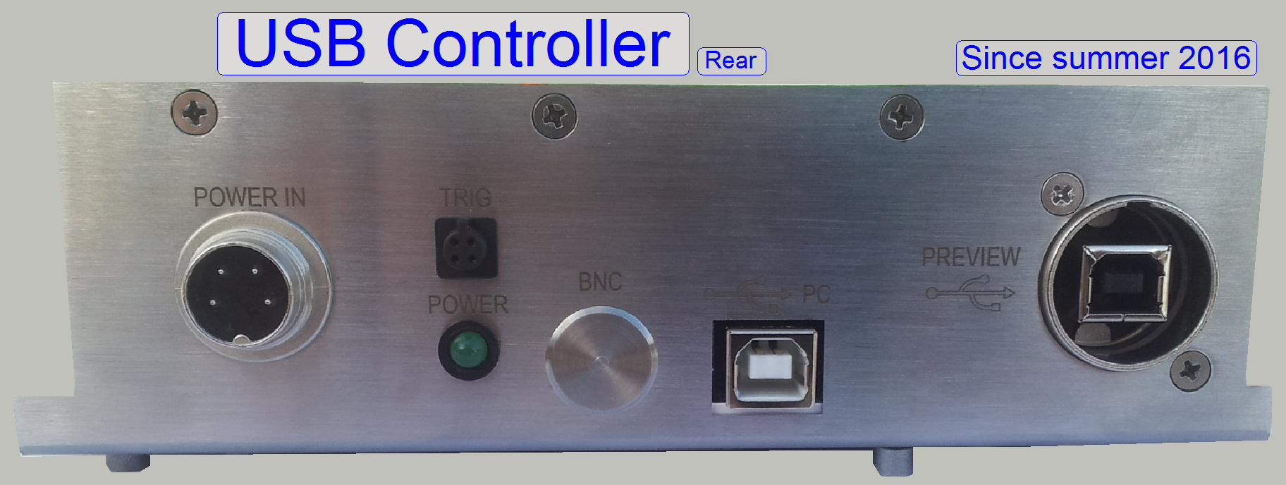 Modifications since summer 20116
The BNC connector is left out and the trigger cable connector works for the
scan camera, especially for the
“Grasshopper3”.
The connector for the preview camera is always a USB 2.0 B-Type
Receptacle.
|
USB controller labels;
summer 2016 |
|||
|
Unit |
SCAN |
|
DESK |
|
RGB BF
illumination |
LBF-1 |
LBG-1 |
LBO-1 |
|
X-Motor |
STF-1 |
STG-1 |
STO-1 |
|
Y-Motor |
STF-2 |
STG-2 |
STO-2 |
|
Z-Motor |
STF-3 |
STG-3 |
STO-3 |
|
DC control |
DCF-1 |
DCG-1 |
DCL-1 |
|
Objective
changer |
DOF-1 |
DOG-1 |
---- |
|
Preview
illumination |
BGF-1 |
BGG-1 |
BGO-1 |
|
Barcode
illumination |
|
|
BGL-O |
|
RGB BF trigger |
LTF-1 |
LTG-1 |
LTO-1 |
|
Tray Loader
motor |
---- |
STG-5 |
---- |
|
Slide loader
motor |
---- |
STG-6 |
---- |
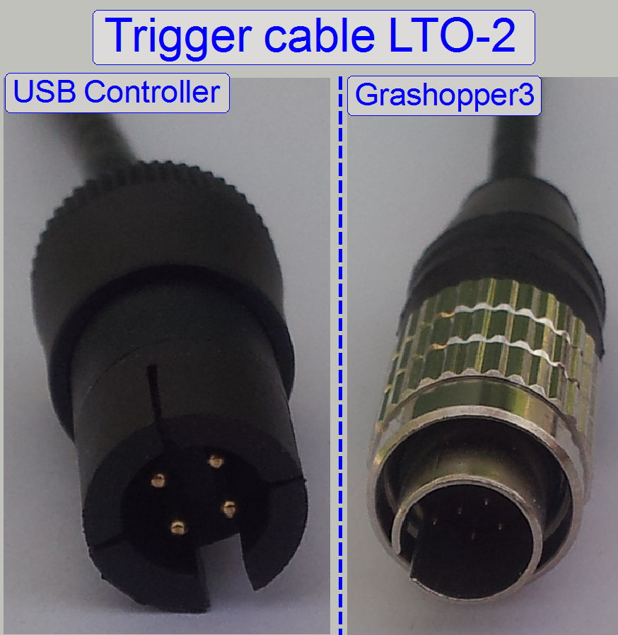
The trigger cable LTO-2 is used during only BF scan procedures (DESK; MIDI_BF,
SCAN_BF) with the camera “Grasshopper3”.
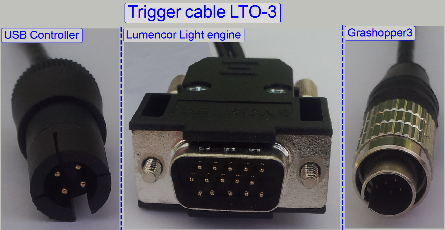
The trigger cable LTO-3 is used during BF and FL scan procedures with
the camera “Grasshopper3” (SCAN,
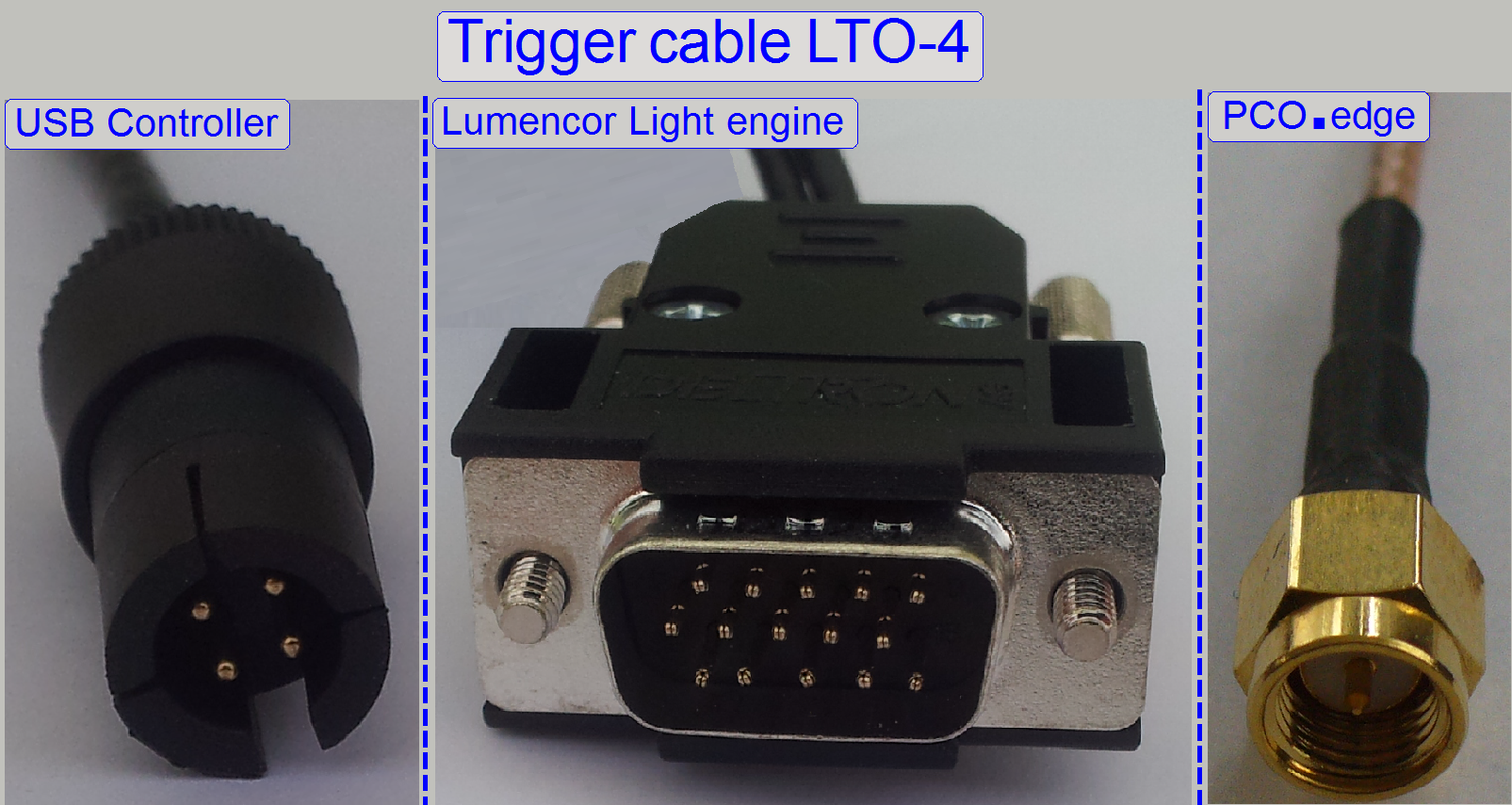
The trigger cable LTO-4 is used during BF and FL scan procedures with the
camera “PCO.edge” (SCAN,
The USB controller receives the command for the units from the program
SlideScanner.exe (the scan program) or the SlideScannerService.exe (the service program) via the Scanner
control port of the PC and the USB cable.
All units that contain separate
electronics (stepper motors and DC-controller) are connected via a bus system.
To differentiate the units, connected to the USB controller, each stepper motor
electronics and the DC-controller as well has an address. Each data transfer
starts with the specified address for the unit and is listen by all units at
the same time, but only this unit receives the message, which internal address
and  the message address is identical. The stepper
electronics can receive commands (number of steps to go and direction) and can
send status information (desired position reached and the status of the sensors
Home1 and Home2). The status information
will be send via the USB cable to the software, hereby the address of the unit
is used also.
the message address is identical. The stepper
electronics can receive commands (number of steps to go and direction) and can
send status information (desired position reached and the status of the sensors
Home1 and Home2). The status information
will be send via the USB cable to the software, hereby the address of the unit
is used also.
With this solution it is possible
to change the stepper motor cable with another stepper motor cable (e.g. for
fault detection) without any risk or functional restrictions. The label of the
cable for digital electronics has no reason in functionality; it differentiates
the cables from each other instead, because some cables are shorter than
others.
Important
The
construction of the controller powering on the board and the power supply does
allow the drive of maximal 2 stepper motors at the same time!
· Please
take this into account, if you are working with the service program and the
batch test program module!
![]() Scanner
cabling and power supply
Scanner
cabling and power supply
 USB- and
DC-electronics box mounting
USB- and
DC-electronics box mounting
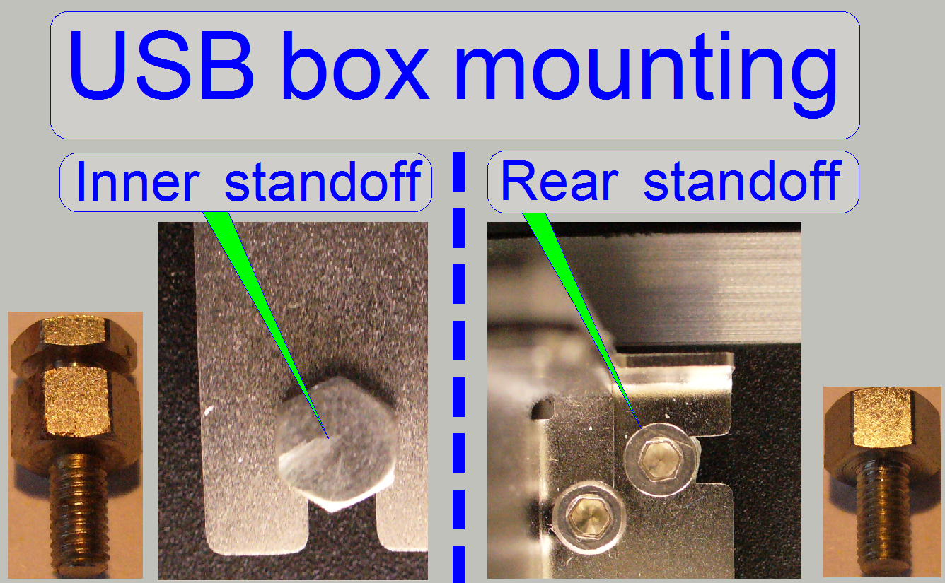
To allow an easy exchange of the USB controller box, the inner (not
reachable) standoffs have a slot, in which the unit is shifted in; during the
rear (reachable with the
screw driver) standoffs are fixing the USB- or DC-controller box by using a
bolt.
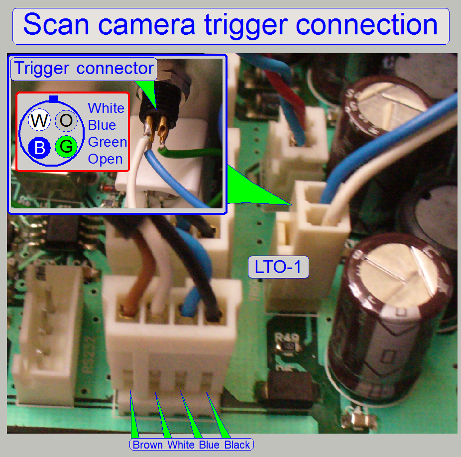
The trigger connector is used to allow hardware triggering of the scan
camera and the FL illumination unit. Momentarily the camera Grasshopper 3 and
the Lumencor SPECTRA light engine is controlled via this output.
- If the camera
is not recognized after changing the USB controller unit, please check the
correct cabling and the connections as shown on the right.
USB B-type to A-type receptacle
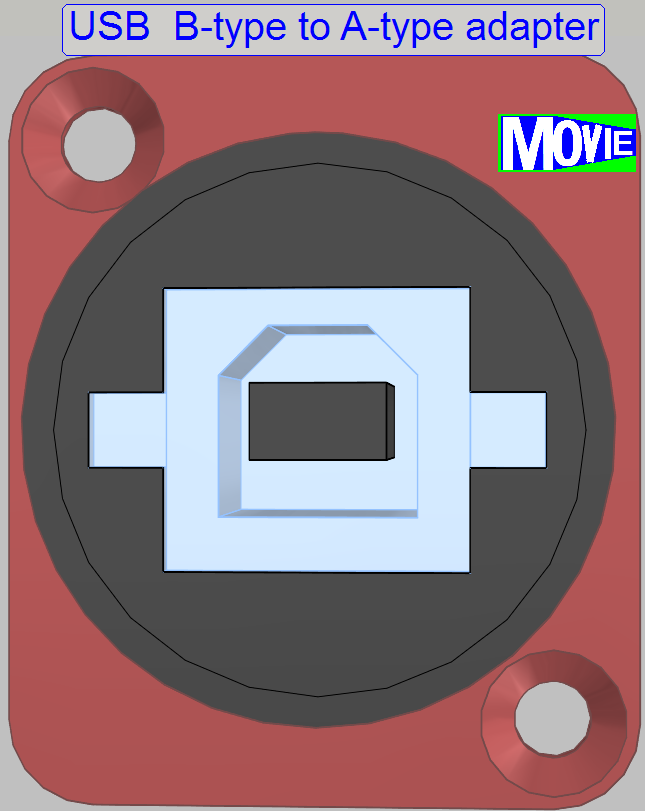 The adapter realizes the connection of the
internal A-type plug of the preview camera cable to the USB B-type plug of the
USB cable to the computer.
The adapter realizes the connection of the
internal A-type plug of the preview camera cable to the USB B-type plug of the
USB cable to the computer.
· ![]() “How
to check the preview camera”
“How
to check the preview camera”
|
Address of scanner
unit |
||
|
Unit |
Address |
Type |
|
X-Y-Z
control |
00 |
C_P |
|
USB-controller |
01 |
All |
|
DC-controller |
02 |
P_S_M_D |
|
X-motor |
03 |
S_M_D |
|
Y-motor |
04 |
S_M_D |
|
Z-motor |
05 |
S_M_D |
|
Turret
unit |
06 |
S_M_P |
|
Tray
loader motor |
07 |
M_C |
|
Slide
loader motor |
08 |
M_C |
|
Objective
changer |
09 |
C_P_S_M |
|
Camera
changer |
10 |
P |
|
RGB
BF illumination |
11 |
C_S_M_D_II |
|
Reserve |
12 |
--- |
|
Immersion
liquid unit |
13 |
C |
|
Mechanical
shutter |
14 |
C |
|
Switch
board |
15 |
C_P |
|
Legend:
C=Confocal; P=P250; S=SCAN; M= |
||
The addresses are used by the scan program and the service program to
select the unit; these addresses are programmed into the specified unit and can
be changed via special software only. It is important, that none of these
addresses should exist twice inside of one Pannoramic scanner, otherwise
command or status mismatch occurs.
If data transfer is in progress, all addressable units listen to the
address of the data stream; if the address of the unit is identical with the
address of the data stream, the addressed unit is found and this receives the
information.
![]() “Cabling
of addressable units”
“Cabling
of addressable units”
Address assigning tool Serial.exe and start “Serial.exe”
 The EEPROM stores the
scanner specific parameters and these are collected in the files
MicroscopeConfiguration.ini and MicroscopeSettings.ini. To ensure an always
proper functioning of the scanner, the content of the EEPROM should be updated
after adjustments are done or units are exchanged and parameter values are
modified. The EEPROM is a part of the USB controllers PCB.
The EEPROM stores the
scanner specific parameters and these are collected in the files
MicroscopeConfiguration.ini and MicroscopeSettings.ini. To ensure an always
proper functioning of the scanner, the content of the EEPROM should be updated
after adjustments are done or units are exchanged and parameter values are
modified. The EEPROM is a part of the USB controllers PCB.
·
To update the content, the EEPROM should be cleared
with the service program.
·
If the scan software is started and the EEPROM is empty,
the content of the appropriate *.ini files will be written automatically from
the HDD into the EEPROM.
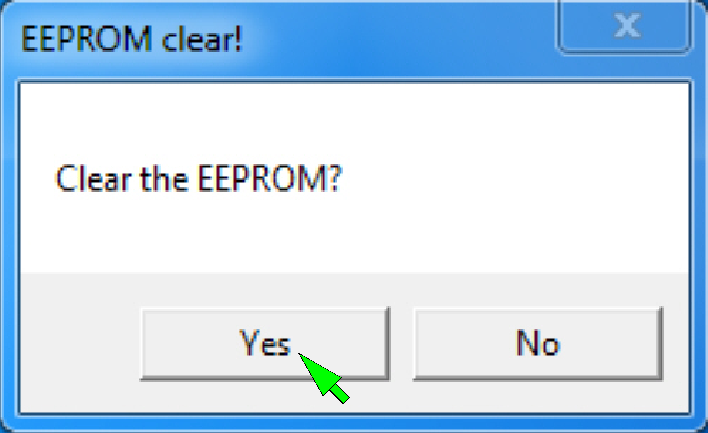
1. Start the program
“SlideScannerService.exe”, option “EEPROM clear”.
2. Answer the
dialogue with “Yes”; then the EEPROM is cleared.
3. Exit the service
program with “Exit”
4. Start the program
“SlideScanner.exe”; the *.ini-files will be automatically saved from the
appropriate HDD folder into the EEPROM during startup of the scan program, if
the EEPROM is empty.
![]() “Service program”; clear
EEPROM
“Service program”; clear
EEPROM
Compressed content of the EEPROM (P250, SCAN,
The compression of the EEPROM content is required since the software version
1.16, because there are newly implemented parameters and the capacity of the
EEPROM is limited to be 2kB.
· By compressing the
content, memory space is won.
In systems, delivered with the version 1.16 the modified handling of the
EEPROM content will not be noticed by the user; the files
“MicroscopeConfiguration.ini” and “MicroscopeSettings.ini” staying on the HDD
in uncompressed form.
· If the EEPROM
content is written, the files “MicroscopeConfiguration.ini” and
“MicroscopeSettings.ini” will be compressed before these are stored in the
EEPROM.
· If the EEPROM is
read, the content will be uncompressed before it is stored as file
“MicroscopeConfiguration.ini” and “MicroscopeSettings.ini” on the HDD.
If an upgrade is made (from the version 1.15 or lower to the version
1.16) the content in the EEPROM is uncompressed but the version 1.16 expects a
compressed content; therefore:
Before you are installing the software version 1.16
· Make sure; the
content of the files “MicroscopeConfiguration.ini” and “MicroscopeSettings.ini”
is the most recent content on the HDD.
· Save these files
to a save place
Install the software version 1.16
· Start the program
“SlideScanner.exe” first time.
· The compression of
the EEPROM content will be done automatically.
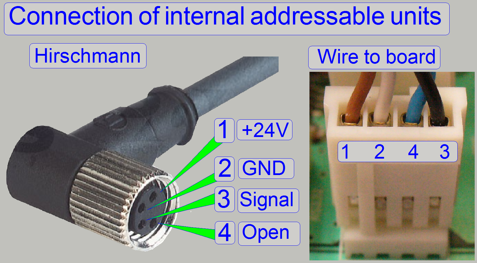
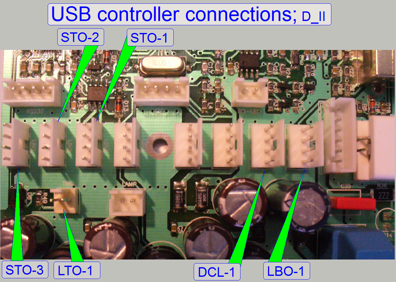
All the addressable units are connected with the “Hirschmann” connector;
the connection is secured with a knurled nut. On the other end of the cable a
“wire to board” connector is used.

Attention
Please switch off the power supply before cable connecting or
disconnecting.
The internal construction of the DC-controllers is different to each
other; the number of the connected cables is limited or extended according to
the requirements.
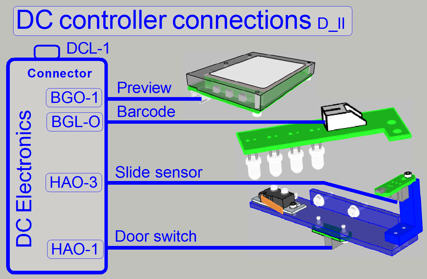
The DC-controller switches the preview illumination on or off; collects
the status information of the connected sensors and transmits these to the
USB-controller.
 About basics, theory and
principles please refer to:
About basics, theory and
principles please refer to:
http://www.solarbotics.net/library/pdflib/pdf/motorbas.pdf
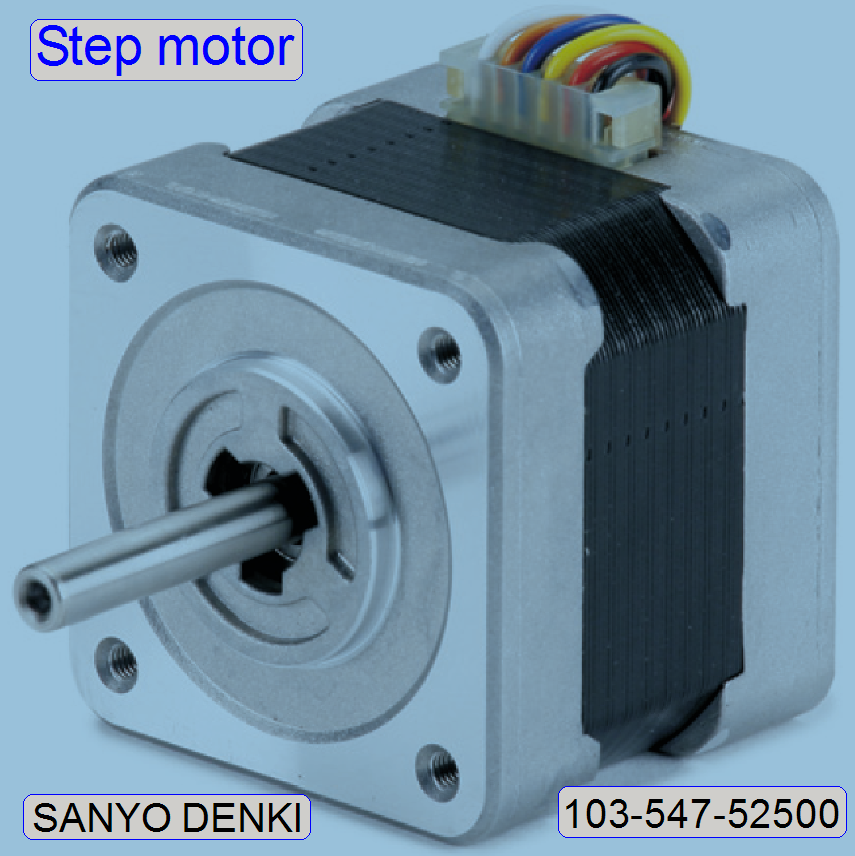
Stepper
motor basics (stored)
Drive circuit basics (stored)
Stepper motor and driver (stored)
External
recirculation diodes (stored)
Stepper motor driving (stored)
Stepper motors 2011 (stored)
Electrical components
Background (preview) illumination
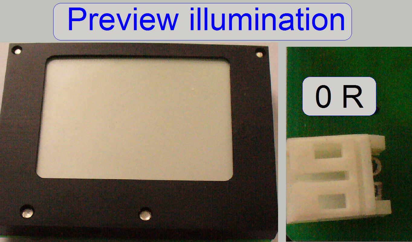 The preview illumination
consists of 6 LEDs and is used to illuminate the scan area part of the slide
and makes so the sample visible for the preview camera.
The preview illumination
consists of 6 LEDs and is used to illuminate the scan area part of the slide
and makes so the sample visible for the preview camera.
.
![]() LED Wikipedia
LED Wikipedia
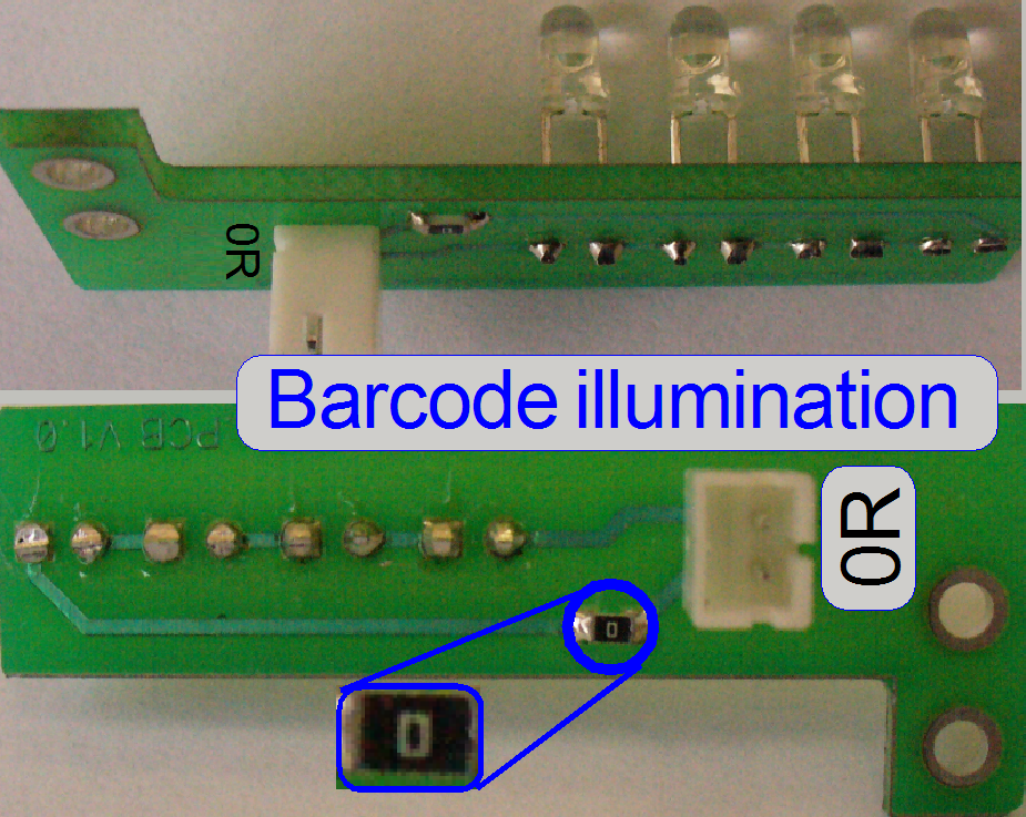 The barcode
illumination consists of four LEDs and is used to illuminate the barcode area
of the slide and makes so the barcode visible for the preview camera.
The barcode
illumination consists of four LEDs and is used to illuminate the barcode area
of the slide and makes so the barcode visible for the preview camera.
![]() LED Wikipedia
LED Wikipedia
RGB
BF illumination unit
Modifications since summer 2016
By using a monochrome scan camera for brightfield scan sessions also,
the FL scan camera as well as the camera changer unit can be left out of the
equipment, because the same camera can be used for BF and FL scan sessions.
On the other side, to create color information for the BF scanned
tissue, the tissue needs to be captured 3 times; each image is illuminated with
another color.
To do this, an RGB illumination unit is required.
By triggering the illumination unit with the shutter of the camera, a
Red, a Green and a Blue illuminated image of the Field of View will be created.
Each image contains the grey scale of the used wavelength (range); so the
partial intensity of the appropriate color is known. By assembling the three images to a Field of
View and using the software coloring method (combining the intensity of gray
from each taken image for each pixel), the true color information of each pixel
is found.
By using cameras with a large image sensor, low shutter time and high
pixel resolution, the scan time of the tissue can be held in acceptable
boundaries and the result is an image with high resolution and high color
fidelity.
|
Connections
of RGB BF illumination |
||
|
Number |
Name |
Label |
|
1 |
LED for
Blue light |
|
|
2 |
LED for
Green light |
|
|
3 |
LED for
Red light |
|
|
4 |
Camera
trigger |
LTO-1 |
|
5 |
Reserve |
|
|
6 |
Reserve |
|
|
7 |
Bus
connector |
LBO-1 |
|
8 |
Reserve |
|
|
|
||
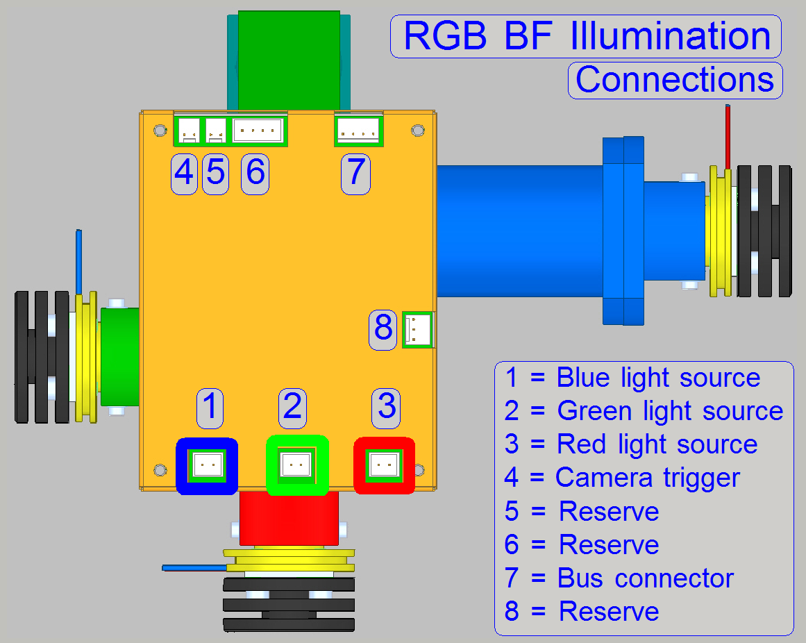
· Please
connect the appropriate cable to the corresponding connector!
5W
HI-POWER LED White Data Sheet
Power: 5W
Forward Voltage: 3.8V (4.3V max peak)
Current: 1400mA (1500mA max peak)
·
Driving LED without heat sinking device is forbidden.
· It is strongly recommended
that the temperature of lead be not higher than 55ºC.
![]() “Power LED module”
and “Brightfield
RGB illumination unit”
“Power LED module”
and “Brightfield
RGB illumination unit”
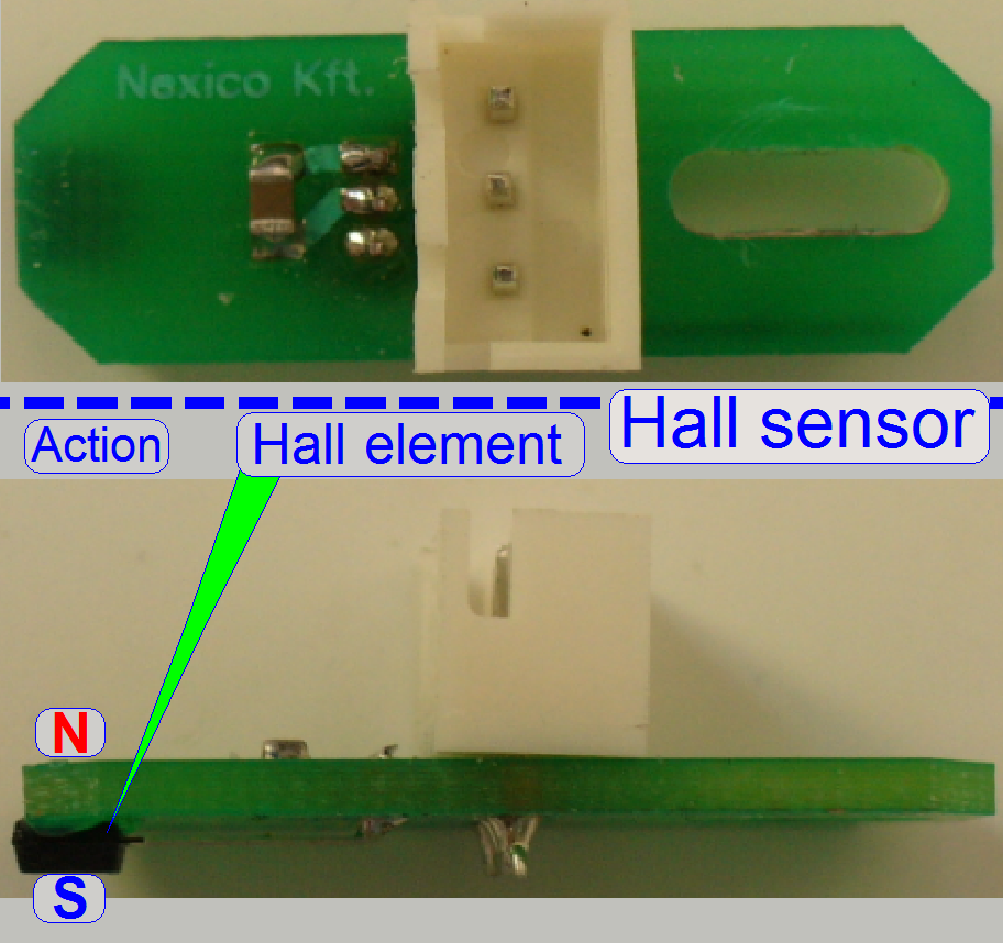
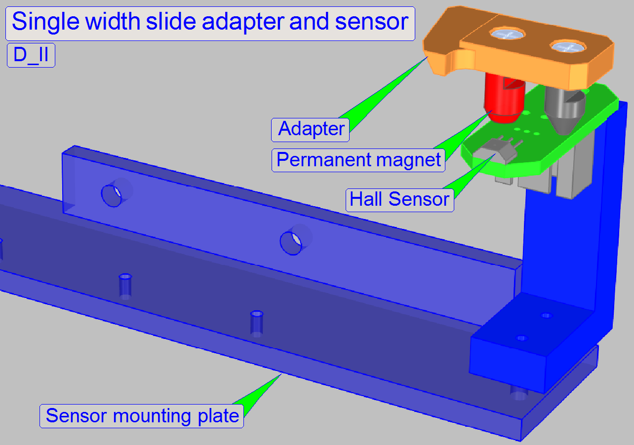
The “Slide sensor” is
realized with Hall element.
- If the south pole of a magnet is over the Hall element or the north
pole on the opposite side, the switch is closed and this state is recognized
by the software.
- If the polarity of the permanent magnet is inverted or a magnetic
field is not present, no action occurs.
- The sensors are so implemented, that the south pole of the permanent
magnet stays over the sensor surface if the action position is reached.
· The sensor
position is adjustable.
· For adjustment procedures see
the appropriate chapters.
· The sensor does
not need maintenance.
![]() “Hall effect” Wikipedia
“Hall effect” Wikipedia
TLE4905L Data sheet; stored
USB-
and DC-controller cabling; summary
Cable labels
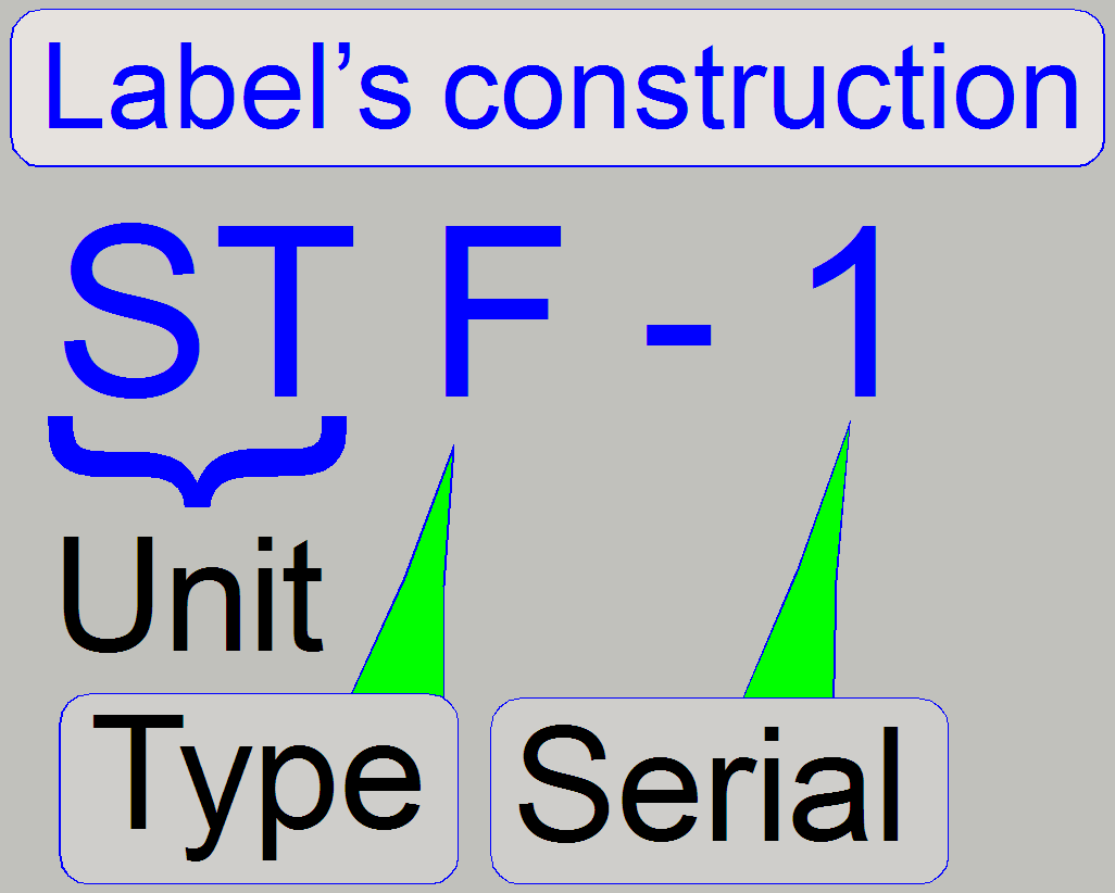
The first 2 letters of the cable label shows the dedicated unit, the 3rd
character defines the electronics version and the scanner type.
Unit
The first 2 letters are defining the unit to be connected.
Type
The type defines mainly the scanner and the electronics version while
delivering the scanner (since 2010). Previously delivered scanners (S_M_D) had
always the letter “C”
Serial
The number “Serial” defines the dedicated unit of the scanner. Often the
unit exists more times (like stepper motors) so the units from the same type
are distinguished. The serial number of stepper motor labels defines mainly
different cable lengths instead of different signals!
Example
The label “STF-
See also: “Cabling of addressable
units” and “Addresses”
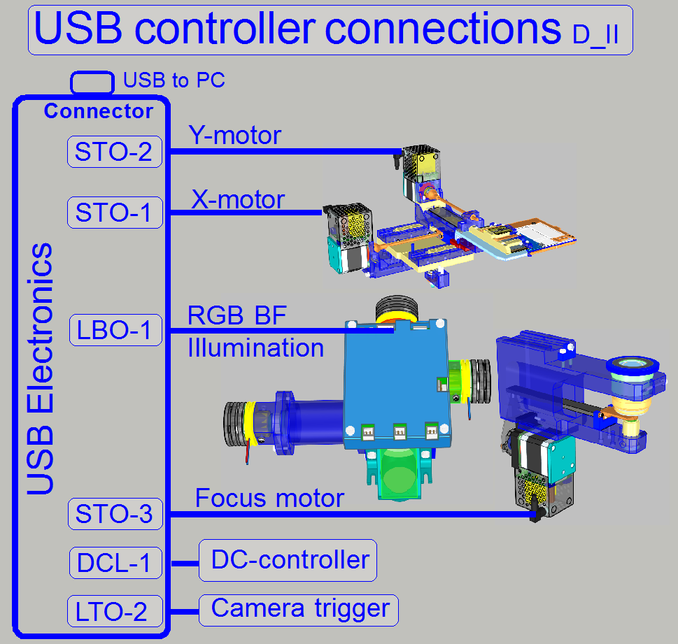
|
USB-controller
cabling; summary |
Cable
label |
|||
|
Unit |
Address |
DESK_II |
MIDI_II |
SCAN_II |
|
Reserve |
00 |
|
|
|
|
USB-controller |
01 |
USB
control cable from PC |
||
|
DC-controller |
02 |
DCL-1 |
DCG-1 |
DCF-1 |
|
X-motor |
03 |
STO-1 |
STG-1 |
STF-1 |
|
Y-motor |
04 |
STO-2 |
STG-2 |
STF-2 |
|
Z-motor;
focus |
05 |
STO-3 |
STG-3 |
STF-3 |
|
Turret
unit |
06 |
- |
STG-4 |
STF-4 |
|
Tray
loader motor |
07 |
- |
STG-5 |
- |
|
Slide
loader motor |
08 |
- |
STG-6 |
- |
|
Objective
changer |
09 |
- |
DOG-1 |
DOF-1 |
|
RGB BF
illumination |
11 |
LBO-1 |
LBG-1 |
LBF-1 |
|
Trigger
cable |
--- |
LTO-1 |
LTG-1 |
LTF-1 |
|
USB
connector; external |
- |
Preview
camera cable to PC |
||
|
USB
connector; internal |
- |
FWI-1 |
FWG-1 |
FWF-1 |
|
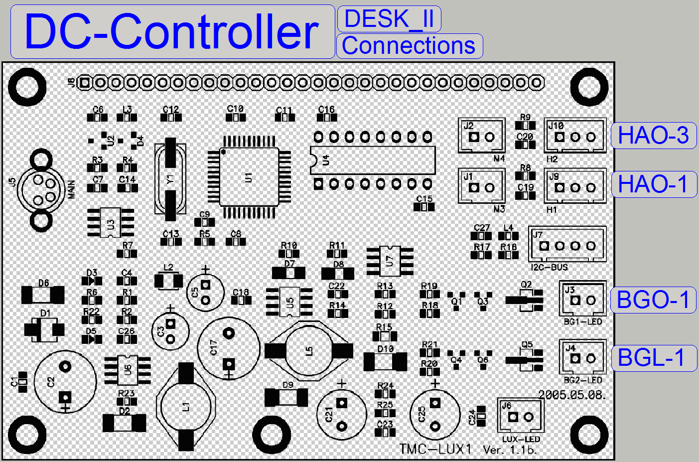
DC-controller
cabling; summary |
Cable
label |
||
|
DESK_II |
MIDI_II |
SCAN_II |
|
|
USB-controller |
DCL-1 |
DCG-1 |
DCF-1 |
|
Door
switch |
HAO-1 |
- |
- |
|
Preview (background)
illumination |
BGO-1 |
BGG-2 |
BGF-2 |
|
Barcode
illumination |
BGL-O |
BGG-1 |
- |
|
Slide
sensor |
- |
HAG-2 |
- |
|
Tray
sensor |
- |
HAG-1 |
- |
|
Left (input)
magazine sensor |
- |
- |
OPF-1 |
|
Right (output)
magazine sensor |
- |
- |
OPF-2 |
|
Magazine
loader sensor |
- |
- |
HAF-1 |
|
Magazine
feeder sensor |
- |
- |
HAF-2 |
|
Slide
loader cable |
- |
- |
HMF-1 |
|
Magazine
loader motor |
- |
- |
DMF-1 |
|
Magazine
feeder motor |
- |
- |
DMF-2 |
|
Slide loader
DC motor |
- |
- |
DMF-3 |