Stepper
motor
Following description summarizes information about stepper motors, used
in Pannoramic scanners.
- Principally,
in Pannoramic scanners 2-phase stepper motors
are used, the resolution is 200 full-steps/revolution or 3200µ-steps/revolution.
- The focus
unit in the P250 has a higher resolution, because this scanner is able to
scan slides of a thickness with 1.20mm. Therefore, this focus motor uses a
resolution of 400 full-steps/revolution or 6400µ-steps/revolution.
- In the
scanners SMD_II 5-phase stepper motors are used to reduce resonance and
vibration. The higher resolution of 1000full-steps/revolution
(0.36°/steps) will be transformed into 200full-steps (X-Y-stage) or
400full-steps (Focus unit). This way, the unit's working principle and mechanical
construction is nearly the same as in the p250.
Contents
Step
control of stepper motors
Construction
of the stepper motor
Construction of the motor unit
Types
of used 2-phase stepper motors

SANYO DENKI 103-547-52500; X, Turret, Camera changer;
Step angle (full step) = 1.8° ± 0.09°; 200 full steps/revolution or 3200µ-steps/revolution
(micro step);
![]() “Sanyo_Step_103_547_52500.pdf”
“Sanyo_Step_103_547_52500.pdf”
SANYO DENKI 103-547-52300; Y-motor;
Step angle (full step) = 1.8° ± 0.09°; 200 full steps/revolution or
3200µ-steps/revolution (micro step);
Sanyo Denki SH-1422-0441; Focus unit, P250;
Step angle (full step) = 0.9° ±
0.045° 400 full steps/revolution or
6400µ-steps/revolution (micro step);
 Nanotec ST2018L0804-A; ND filter unit;
Step angle
(full step) = 1.8° ± 0.09°; 200 full steps/revolution or 3200steps/revolution (micro
step);
 “ST2018L0804-A” and “Stepper Motor - NEMA 8”
About
basics, theory and principles please refer to:
http://www.solarbotics.net/library/pdflib/pdf/motorbas.pdf
Stepper
motor basics (stored)
Drive circuit basics (stored)
Stepper motor and driver (stored)
External
recirculation diodes (stored)
Stepper motor
driving (stored)
Stepper motors 2011 (stored)
Stepper motors/knowledge Link ©Nanotec
Operating principle Link YouTube
How a Stepper Motor works Link ©Nanotec
Schrittmotoren Link ©Nanotec
Aufbau und Funktion Link ©Nanotec
· Adobe®
flash player needs to be installed and allowed by the browser.
Types of used 5-phase
stepper motors

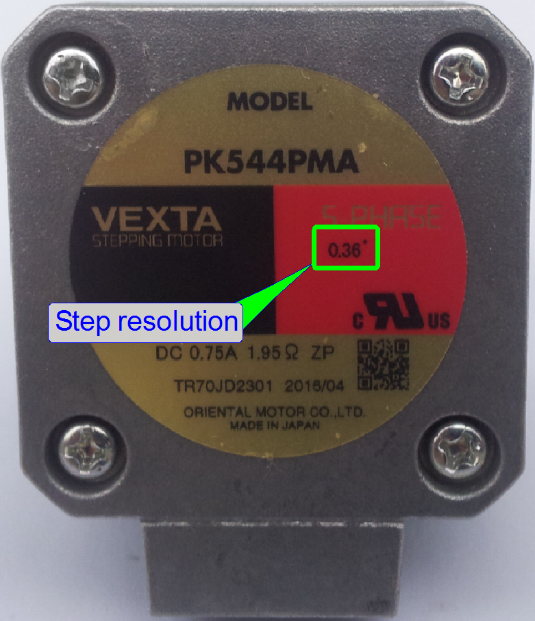
ORIENTAL MOTOR
VEXTA
Manufacturer: ORIENTAL
MOTOR
Types: PK544PA
or B; PK544PMA or B
PK544PA single
shaft with a resolution of 500full-steps/revolution; 0.72°/step
PK544PMA single
shaft with a resolution of 1000full-steps/revolution; 0.36°/step
The last letter of the type may be “A” or “B”.
The letter “A” means front shaft only while “B” means front and rear
shaft present.
·
All stepper motors in Pannoramic
scanners are unexceptionally and always driven in micro stepping; this way very
precise movement is reached.
·
One revolution (full turn) of the motor axle is
divided into 3200 steps.
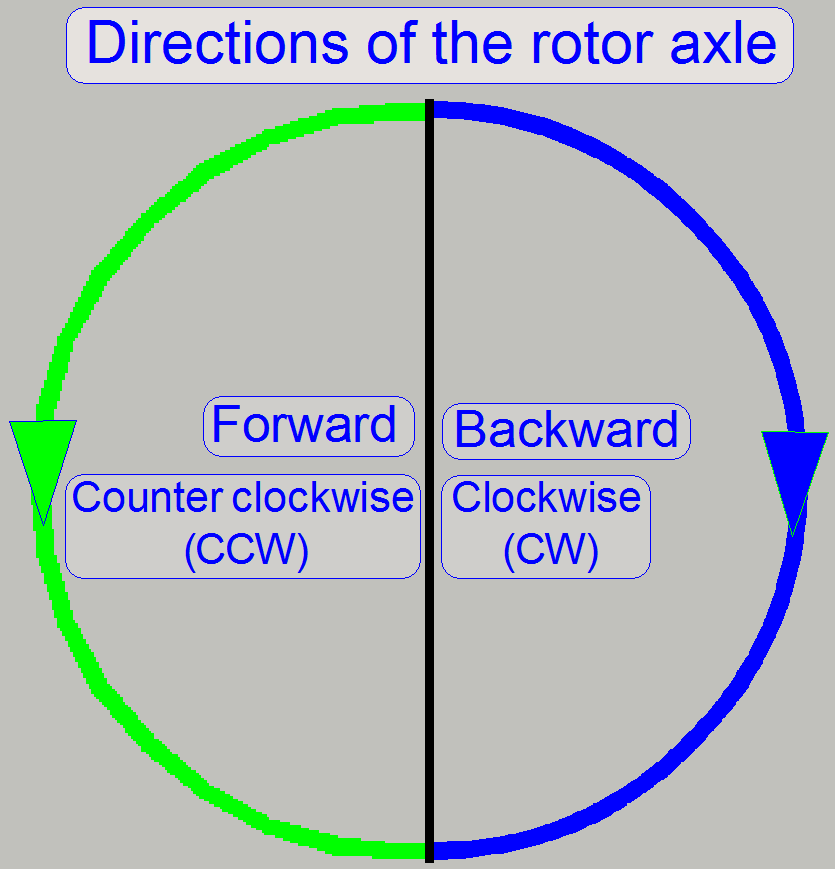
·
The forward direction of the motors axle is counter
clock wise, CCW.
·
The parts and units of the stepper motors need neither
maintenance nor mechanical adjustments.
Step control of stepper motors
· The scan software
sends to the stepper motor electronics the number of steps to go (any number
between the hardware limits of the appropriate unit; the number will be limited
to the defined HW limit), the rotation direction (CW or CCW) and the value for
the u-time.
· The stepper motor
controller calculates the speed wave form of the motor (see below “The inertia”) and executes
the number of steps to go.
· If the command
(number of steps to go and direction) is executed, the stepper motor controller
acknowledges the command with the appropriate status (the controller sent the
number of pulses to the motor driver circuit); regardless steps are lost or
not!
· In the Low Level
Service part of the Service program the hardware limits are not checked, so the
number of issued motor steps can be more than the hardware is able to move;
lost steps can occur! This possibility is used to check and define the
mechanical limits of the appropriate stepper motor driven construction.
![]() Stepper motors Wikipedia
Stepper motors Wikipedia
· Adobe®
flash player needs to be installed and allowed by the browser.
“How to define the hardware limits”
These motor types are mainly used in scanners, developed until summer
2016 and later in units, that are seldom moved or vibration, resonance and
noise is not important for the scan process (scan process even not in
progress).
Stepper
motors with
control electronics mounted
·
All the stepper motors in the scanners are unexceptionally
and always driven in micro stepping; this way very precise movement is reached.
·
One revolution (full turn) of the motor axle is
divided into 3200 steps (except the focus motor).
·
The forward direction of the motor’s axle is counter
clock wise, CCW.
·
The parts and units of the stepper motors need neither
maintenance nor mechanical adjustments.
Stepper motors without
control
electronics mounted
In the P250 the construction and the type of some stepper motors are
modified in relation to the DESK,
The communication and control protocol is not modified, but the control
electronics was separated from the motor; it is situated in the “X-Y-Z-ND-motor
and Flash light control.”.
X-
and Y-stage motors
 The motor type in
the P250 is the same (3200µ-steps/revolution) as in the DESK,
The motor type in
the P250 is the same (3200µ-steps/revolution) as in the DESK,
- The stepper
motor cables are connected to the X- respective Y-part of the “X-Y-Z-ND-motor
and Flash light” control electronics.
- The Y-motor
type is different, because this motor has a shaft on the rotor’s rear side
also.
Focus
motor
In the P250, the focus motor has a resolution of 6400
steps/revolution and does not contain control electronics; see above “X-Y-Z-ND-motor
and Flash light” control electronics.
- The cables are connected to the Z-part of the “X-Y-Z-ND-motor
and Flash light” control electronics.
ND-motor
The neutral density unit’s drive motor has a
resolution of 200 full steps/revolution (3200micro steps) and is used to drive
the ND-disc in the ND-unit housing.
![]() “ND filter unit
stepper motor” and “ND filter unit”
“ND filter unit
stepper motor” and “ND filter unit”
Step control of stepper motors
· The scan software
sends to the stepper motor electronics the number of steps to go (any number
between the hardware limits of the appropriate unit; the number will be limited
to the defined HW limit), the rotation direction (CW or CCW) and the value for the
u-time.
· The stepper motor
controller calculates the speed wave form of the motor (see below “The inertia”) and executes
the number of steps to go.
· If the command
(number of steps to go and direction) is executed, the stepper motor controller
acknowledges the command with the appropriate status (the controller sent the
number of pulses to the motor driver circuit); regardless steps are lost or
not!
· In the Low Level
Service part of the Service program the hardware limits are not checked, so the
number of issued motor steps can be more than the hardware is able to move;
lost steps can occur! This possibility is used to check and define the
mechanical limits of the appropriate stepper motor driven construction.
![]() “How to define the hardware limits”
“How to define the hardware limits”
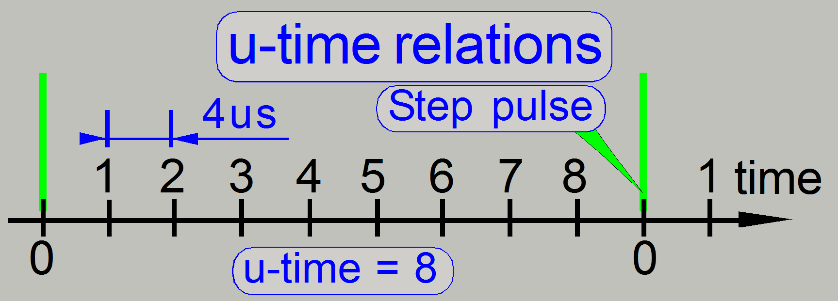 The “u-time”
parameter means the “time of one micro step” (“u” means “μ”
(micro)) and is used to define the time, evaluated between the
execution of 2 micro steps of the rotor.
The “u-time”
parameter means the “time of one micro step” (“u” means “μ”
(micro)) and is used to define the time, evaluated between the
execution of 2 micro steps of the rotor.- The u-time is
used as a factor and defines the pause time between two steps that
following each other if the rotor rotates with the full speed. This factor
affects both, the full speed and the torque of the rotor as well; the
torque and the speed are nonlinear reciprocal to each other.
- The u-time is
defined for each motor separate in the software, depending on the driven
mechanics; e.g. the turret motor has to handle a higher load then the
focus motor.
- This value
defines the possible full speed of the stepper motor.
- The value of
the u-time may be varied between 8 and 64; lower values define higher
speed with reduced torque, higher values define higher torque with lower
speed.
Calculate
the u-time
Time
between two step pulses = (u-time + 1) x 4μs
Usable
values are: 8 ≤ u-time ≤ 64
A value, lower then u-time=8 should
not be used, because missed steps can occur or the mechanical drive will not
start. If the value of the u-time will be increased, the motor speed reduces
and the torque increases; noise, vibration and resonance are also influenced.
The
following tables show parameter values of the stepper motors, used in the P250,
during different actions or procedures. These values can be used to configure
the stepper motors in the part “B-test” of the service program.
|
P250;
Slide insert and removal values |
|||||
|
Param. Unit |
U-time |
U-time devisor |
Acceleration |
Current |
Current devisor |
|
X-motor |
512 |
1 |
256 |
16 |
917568 |
|
Y-motor |
512 |
1 |
256 |
16 |
917568 |
|
Z-motor |
512 |
1 |
100 |
16 |
917568 |
|
ND-motor |
512 |
2 |
256 |
16 |
917568 |
|
Turret; gear |
16 |
1 |
256 |
64 |
1 |
|
Turret; belt |
4 |
3 |
256 |
150 |
1 |
|
C. Changer |
12 |
1 |
8 |
64 |
1 |
|
CC; Home1,2 |
12 |
1 |
256 |
64 |
1 |
|
P250;
default values in the service program |
|||||
|
Param. Unit |
U-time |
U-time devisor |
Acceleration |
Current |
Current devisor |
|
X-motor |
512 |
1 |
100 |
16 |
917568 |
|
Y-motor |
512 |
1 |
100 |
16 |
917568 |
|
Z-motor |
512 |
1 |
100 |
16 |
917568 |
|
ND-motor |
512 |
1 |
100 |
16 |
917568 |
|
Turret; gear |
16 |
1 |
256 |
64 |
1 |
|
Turret; belt |
4 |
1 |
256 |
150 |
1 |
|
C. Changer |
12 |
1 |
8 |
64 |
1 |
|
CC; Home1,2 |
12 |
1 |
256 |
64 |
1 |
|
P250;
Values during focusing procedures |
|||||
|
Param. Unit |
U-time |
U-time devisor |
Acceleration |
Current |
Current devisor |
|
X-motor |
559 |
4 |
256 |
6 |
917568 |
|
Y-motor |
559 |
4 |
768 |
6 |
917568 |
|
Z-motor |
550 |
1 |
300 |
6 |
917568 |
|
ND-motor |
512 |
2 |
256 |
16 |
917568 |
|
Turret; gear |
16 |
1 |
256 |
64 |
1 |
|
Turret; belt |
4 |
3 |
256 |
150 |
1 |
|
C. Changer |
12 |
1 |
8 |
64 |
1 |
|
CC; Home1,2 |
12 |
1 |
256 |
64 |
1 |
|
P250;
Values during slide scan procedures |
|||||
|
Param. Unit |
U-time |
U-time devisor |
Acceleration |
Current |
Current devisor |
|
X-motor |
559 |
4 |
256 |
6 |
917568 |
|
Y-motor |
559 |
4 |
768 |
6 |
917568 |
|
Z-motor |
550 |
1 |
300 |
6 |
917568 |
|
ND-motor |
512 |
2 |
256 |
16 |
917568 |
|
Turret; gear |
16 |
1 |
256 |
64 |
1 |
|
Turret; belt |
4 |
3 |
256 |
150 |
1 |
|
C. Changer |
12 |
1 |
8 |
64 |
1 |
|
CC; Home1,2 |
12 |
1 |
256 |
64 |
1 |
Inertia, speed, torque and noise
 As
common known, the inertia is an mostly unwanted aspect and so it might be a
problem in driven mechanical systems and has to be handled precise, mainly if
we achieve a longitudinal movement resolution of 1μm/rotor step; otherwise
lost steps may occur during the mechanics movement or the defined position is
not reached (the mechanics moved behind the issued number of steps).
As
common known, the inertia is an mostly unwanted aspect and so it might be a
problem in driven mechanical systems and has to be handled precise, mainly if
we achieve a longitudinal movement resolution of 1μm/rotor step; otherwise
lost steps may occur during the mechanics movement or the defined position is
not reached (the mechanics moved behind the issued number of steps).
In Pannoramic
scanners the inertia of the entire mechanical drive is handled by the
controlling of the stepper motors torque and so the speed also.
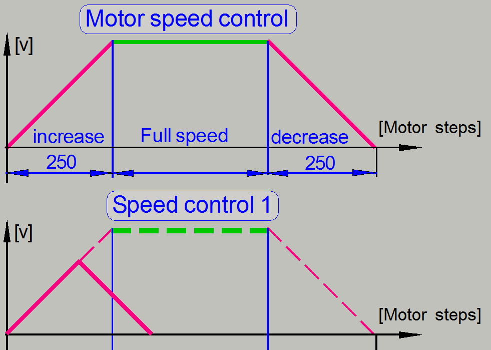
- If the motor
starts to drive, the speed of the rotor will start with the lowest level
and is increased in the first nearly 250 steps to go until the maximal
defined speed is reached.
- The motor
goes the issued number of steps reduced by 500 steps with full speed;
then, in the last nearly 250 steps to go, the rotor speed will be
decreased until the rotor stops again (see motor speed control).
- If there have
to go less then 500 steps, the full speed will not be reached.
- The number of
steps to go will be divided by 2 and so in the first half number of steps
the speed will increase, then the speed is decreased until the number of
issued steps is gone (see “Speed control 1”).
- All these
speed control mechanisms are done by modifying the u-time; the momentarily
appropriate value is defined in the stepper motor controllers “Speed
control table”.
Noise
and vibration will be also affected (in acceptable limits) by the
used value of the u-time;
![]() “How
To Decrease Noise on Your Stepper Motor Driver” and “Designing for quiet,
vibration-free operation”
“How
To Decrease Noise on Your Stepper Motor Driver” and “Designing for quiet,
vibration-free operation”
- The inertia
of the DC-motor driven mechanics is handled by the positioning of the
sensors or the permanent magnets.
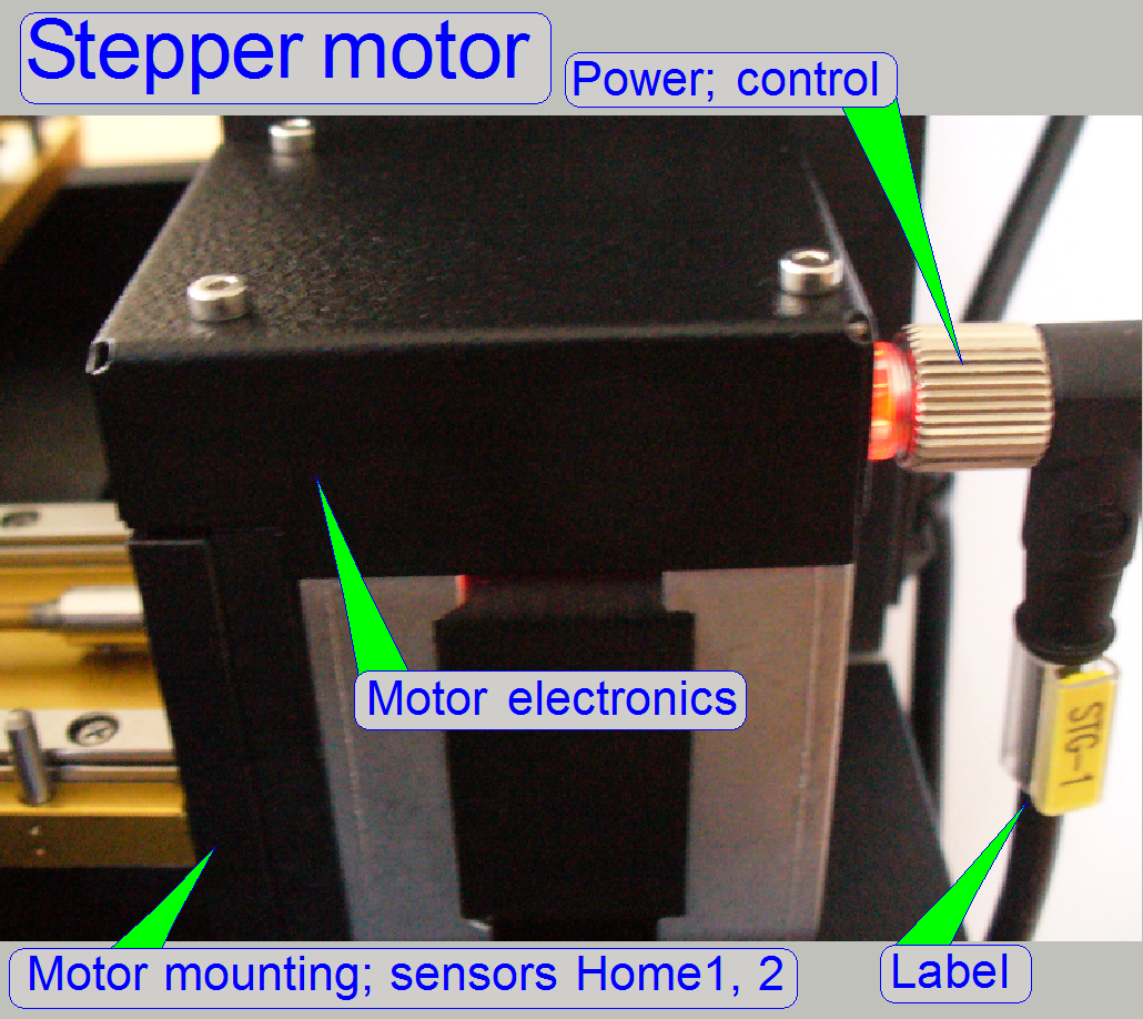
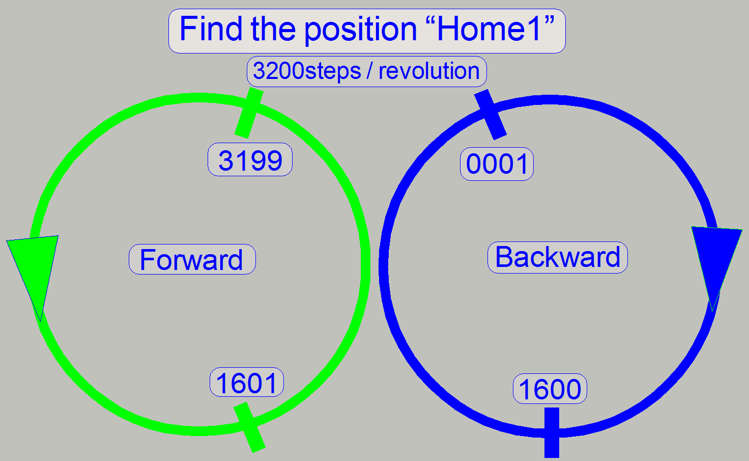
 In the
stepper motor electronics and the motor mounting the sensors for Home1 and
Home2 are located. To reach the start position within one revolution of the
stepper motor’s rotor (mainly if steps are lost or when the power is turned
on), a home position detection sensor is implemented, named “Home1”. This sensor
detects always the start position for counting steps, within one revolution of
the rotor. If the Home1 command is issued and the actual position is in the
range between 1 and 1600, the motor axle rotates backward (CW) to reach the
motor start position. If the actual position is in the range between 1601 and
3199 the motor axle rotates forward (CCW) to find the start position for step
counting. Because the mechanical construction of the stepper motor driven
components needs often more then 1 rotor revolution to fulfill its task, a
second sensor, named “Home2” is implemented. This sensor limit is 342
revolutions of the motor axle. This is a wide limit and will not be reached by
any of the stepper motor driven mechanical constructions in Pannoramic
scanners. To reach the position “Home2” the motor axle is always driven
backward (CW).
In the
stepper motor electronics and the motor mounting the sensors for Home1 and
Home2 are located. To reach the start position within one revolution of the
stepper motor’s rotor (mainly if steps are lost or when the power is turned
on), a home position detection sensor is implemented, named “Home1”. This sensor
detects always the start position for counting steps, within one revolution of
the rotor. If the Home1 command is issued and the actual position is in the
range between 1 and 1600, the motor axle rotates backward (CW) to reach the
motor start position. If the actual position is in the range between 1601 and
3199 the motor axle rotates forward (CCW) to find the start position for step
counting. Because the mechanical construction of the stepper motor driven
components needs often more then 1 rotor revolution to fulfill its task, a
second sensor, named “Home2” is implemented. This sensor limit is 342
revolutions of the motor axle. This is a wide limit and will not be reached by
any of the stepper motor driven mechanical constructions in Pannoramic
scanners. To reach the position “Home2” the motor axle is always driven
backward (CW).
The construction of the sensor Home1 and the fact that
the motor axle moves always backward to reach Home2 is the reason for the
negative hardware limit of the stepper motor driven unit, limited to be less
then 1600 steps in negative direction, counted from Home1, Home2.
![]() “How to define hardware limits”
and “Sensor “Home1” and hardware limits”
“How to define hardware limits”
and “Sensor “Home1” and hardware limits”
Reach the home position
of the mechanical drive
 After
the command Home1 is issued, the motor axle is driven forward or backward as
described above. If the sensor Home1 signals the software that the home
position is reached and we issue the command Home2, the software checks the
state of the sensor Home2 first, before executing the command. If Home2 is
active, movement does not occur; if the Home2 state is inactive the software
drives the motor axle backward until Home2 signals active state. The software
stops motor driving and is checking the state of Home1 again. This is
important, because otherwise the position of Home1 would be different, if the
forward or backward direction was executed. If Home1 is inactive, the motor is
driven forward to find the start position with Home1. If the sensors Home1 and
Home2 are active at the same time, the step counter for counting motor steps is
reset to zero and the home position over the entire mechanical construction is
found.
After
the command Home1 is issued, the motor axle is driven forward or backward as
described above. If the sensor Home1 signals the software that the home
position is reached and we issue the command Home2, the software checks the
state of the sensor Home2 first, before executing the command. If Home2 is
active, movement does not occur; if the Home2 state is inactive the software
drives the motor axle backward until Home2 signals active state. The software
stops motor driving and is checking the state of Home1 again. This is
important, because otherwise the position of Home1 would be different, if the
forward or backward direction was executed. If Home1 is inactive, the motor is
driven forward to find the start position with Home1. If the sensors Home1 and
Home2 are active at the same time, the step counter for counting motor steps is
reset to zero and the home position over the entire mechanical construction is
found.
Construction
of the stepper motor

The 2-pase stepper motors, used in Pannoramic
scanners are almost all from the same type; using the same electronics and
using an identical communication and control protocol.
Differences are given in the mounting of the motor
(sensor cover and motor mounting) and the connection of the motor axle to the mechanical
drive. These connections are individual adapted to the mechanics to be driven.
Furthermore, to make the motor selectable for
information and control data, each motor, used in the Pannoramic
scanner got an address. Each communication pattern contains this address also.
This way, only the addressed motor will receive the information stream, where
the motor address and the data pattern address are identical.
Status and sensor information is transferred by using
the same principle; see also above “Addresses”.

Watch video: Stepper motor components
Types
of the combined sensor cover and motor mounting
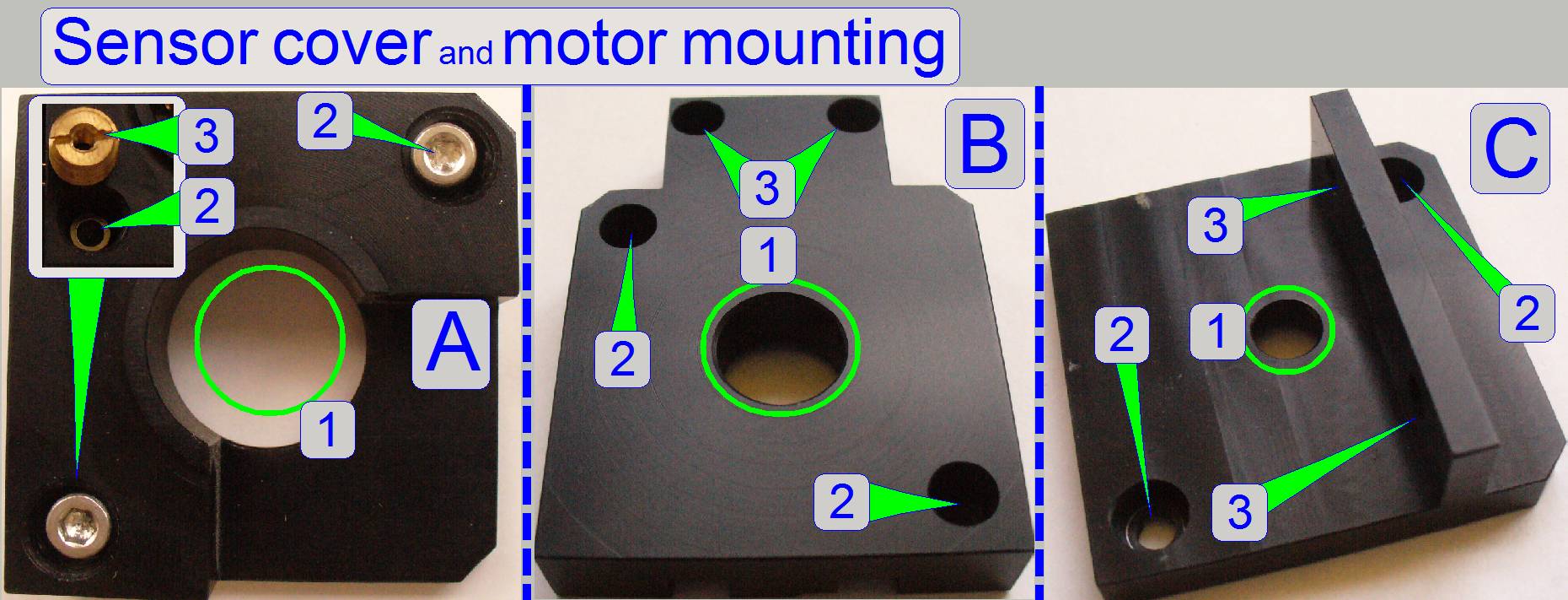 The
shape of the cover on the sensor side is identical for all the three types,
only the connection of the motor to the mechanical drive is different /
modified.
The
shape of the cover on the sensor side is identical for all the three types,
only the connection of the motor to the mechanical drive is different /
modified.
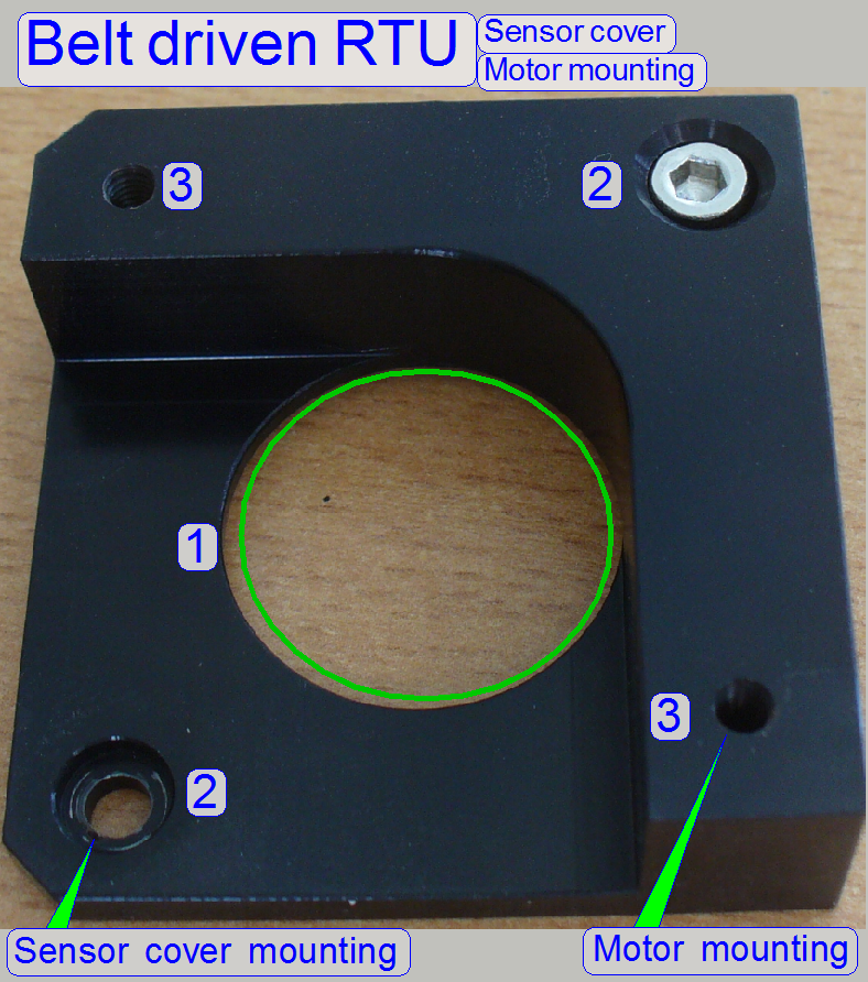
1 = Motor axle drilling
This drilling is always situated in the center of the
mounting; it differs in diameter according to the requirements of the connected
peripheral.
2 = Sensor cover mounting
Two bolts in diagonal position fixing the sensor cover
to the motor.
3 = Motor mounting to the mechanical drive
The motor mounting solution differs according to the
possibilities or requirements, offered by the mechanical drive to be connected.
 A =
Turret motor mounting
A =
Turret motor mounting
The turret motor is
mounted via two mounting nuts (3); these are driven into the threaded drilling
of the sensor cover mounting (2).
B = Focus motor mounting
The focus motor is mounted
to the focus block via the drillings (3).
C= Mounting of all other used stepper motors
The X-motor and the Y-motor are mounted
with this solution.
The drillings (3) are used to fixing the motor to the
appropriate mechanics.
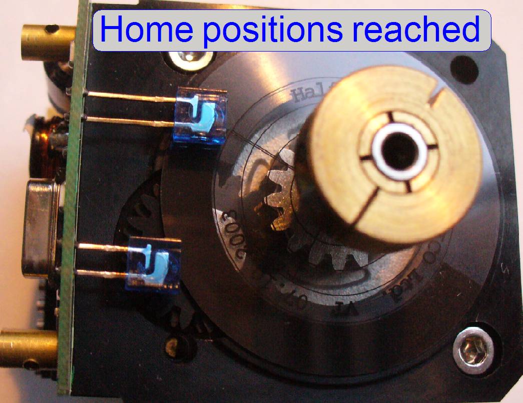 After
removing the “Sensor cover and motor mounting” plate, the sensors Home1 and Home2
becomes visible.
After
removing the “Sensor cover and motor mounting” plate, the sensors Home1 and Home2
becomes visible.
The sensor Home1 is a foil
disc and this is adhesive bonded to the motor axle gear; its position in
relation to the diode Home1 is very important; at the same time, the sensor
Home2 have to be in home position (during gluing the foil disc).
The sensor is used to find the start position for step
counting inside 1 revolution of the motor axle.


The sensor Home2 is realized
with two gear wheels, mounted onto the same axle and both are driven from the
motor axle gear. The sensor Home2 determines and limits the number of possible
revolutions of the rotor for the entire driven mechanics.
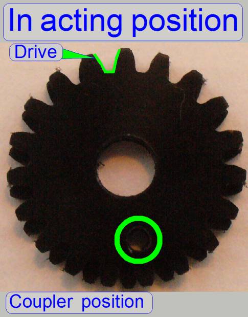
Remark
The “Home2 diode” is bent backward to make the “Home2 hole”
visible; this is not the working position of the diode!

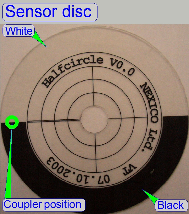
The sensor disc “Home1” consists of a half part black
and a half part translucent (white). If the disc rotates CCW (forward) the transistor
is lightened by a half revolution of the motor axle, if the white part is
illuminated, the other half revolution interrupts the light path to the photo
transistor, if the black part is over the coupler.
· This
way, two edges (transitions) are generated, from white to black and from black
to white.
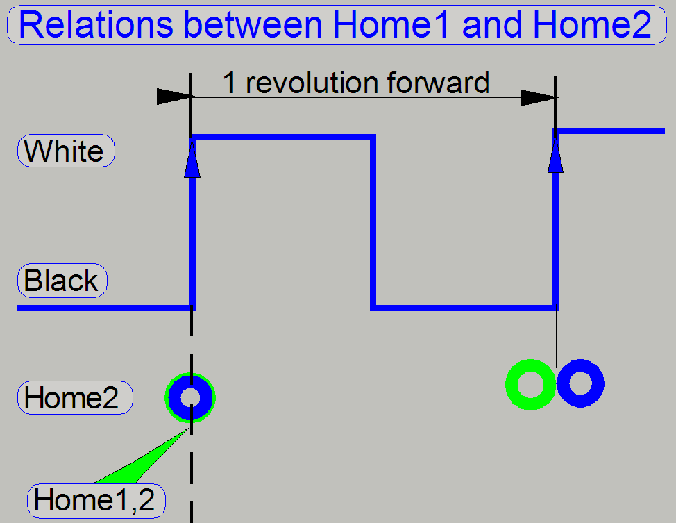
If the disc rotates forward, the transition from black
to white is used to check the state of the Home2 sensor.
The Home1,2 position is reached if the Home1 sensor
had a transition from black to white, the sensor Home2 shows the active state
and the sensor Home1 stays on white (if the direction of rotation is forward).
To ensure, that the same position is used, if the motor rotates backward, the
state of the sensor Home2 is checked by the transition from white to black of
the sensor Home1, and then a forward movement is followed.
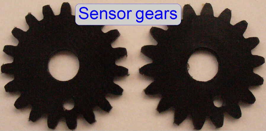 The
Home2 sensor consists of two gearwheels; the cog number differs by 1,
in relation to each other. Each gearwheel has a hole on a specified
position. In the Home2 position the holes fitting each other; light can pass
through the sensor to the photo transistor and the Home2 position is
recognized. The gear wheels are mounted on the same axle and both are driven at
the same time from the gearwheel situated on the motor axle.
The
Home2 sensor consists of two gearwheels; the cog number differs by 1,
in relation to each other. Each gearwheel has a hole on a specified
position. In the Home2 position the holes fitting each other; light can pass
through the sensor to the photo transistor and the Home2 position is
recognized. The gear wheels are mounted on the same axle and both are driven at
the same time from the gearwheel situated on the motor axle.
Because the number of cogs differs by 1, the position
of the holes is different after 1 revolution of the motor axle; the holes are
not fitting each other; light will not arrive to the photo transistor and home
2 is not reached. The number of cogs for the gear wheels was chosen so, that
the Home2 state will be active next time, if the motor axle had done the number
of revolutions, defined by the product of the cog numbers.
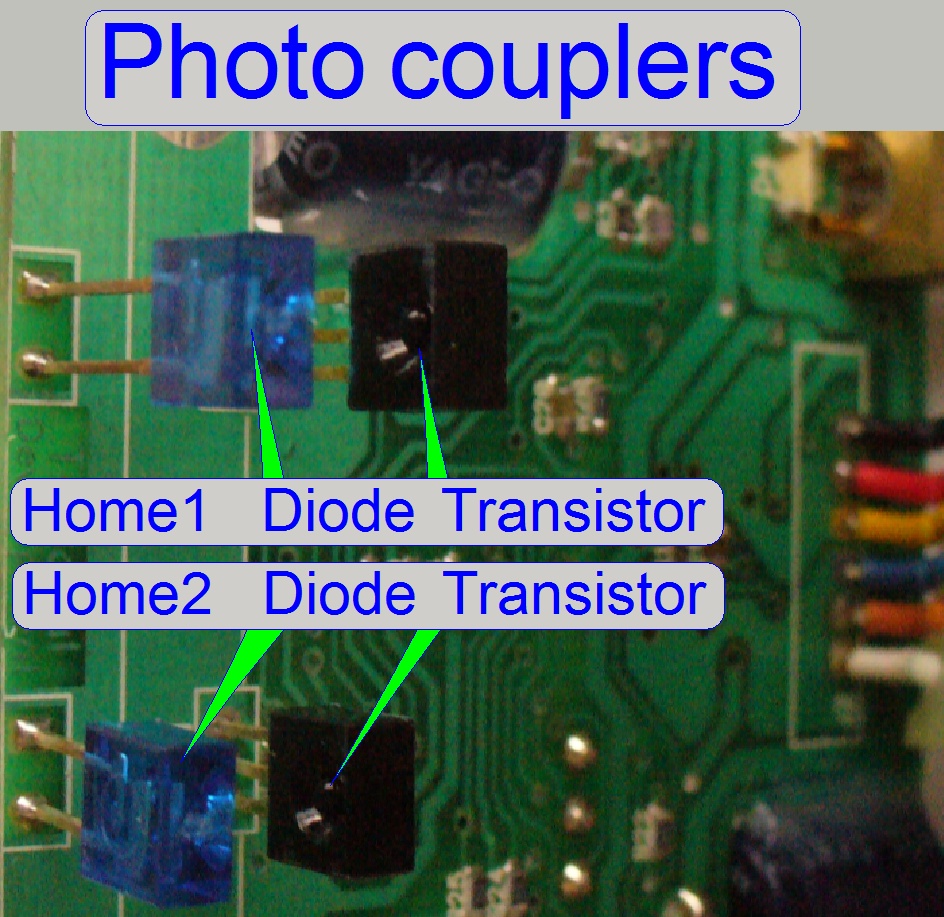
Each sensor has its own photo coupler; it consists of
an infrared LED, acting as the light emitter and an infrared photo transistor, acting
as light receiver. The sensor allows the light of the LED to the transistor if
the acting position is reached; otherwise, the light path between LED and
transistor is broken by the sensor. The state (light / no light) and the
transition edge (Home 1) contain the information; this is recognized by the
electronics and transferred to the software.

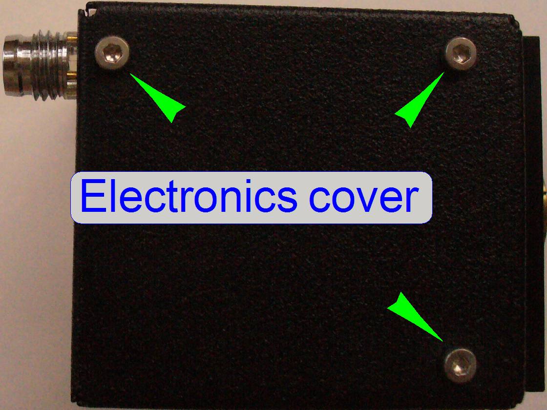 By
removing the PCB cover the PCB becomes visible. The electronics cover is
mounted to the PCB mounting standoffs; increases the mechanical stability of
the connector and contain the cooling plate for the stepper motor driver
circuit.
By
removing the PCB cover the PCB becomes visible. The electronics cover is
mounted to the PCB mounting standoffs; increases the mechanical stability of
the connector and contain the cooling plate for the stepper motor driver
circuit.
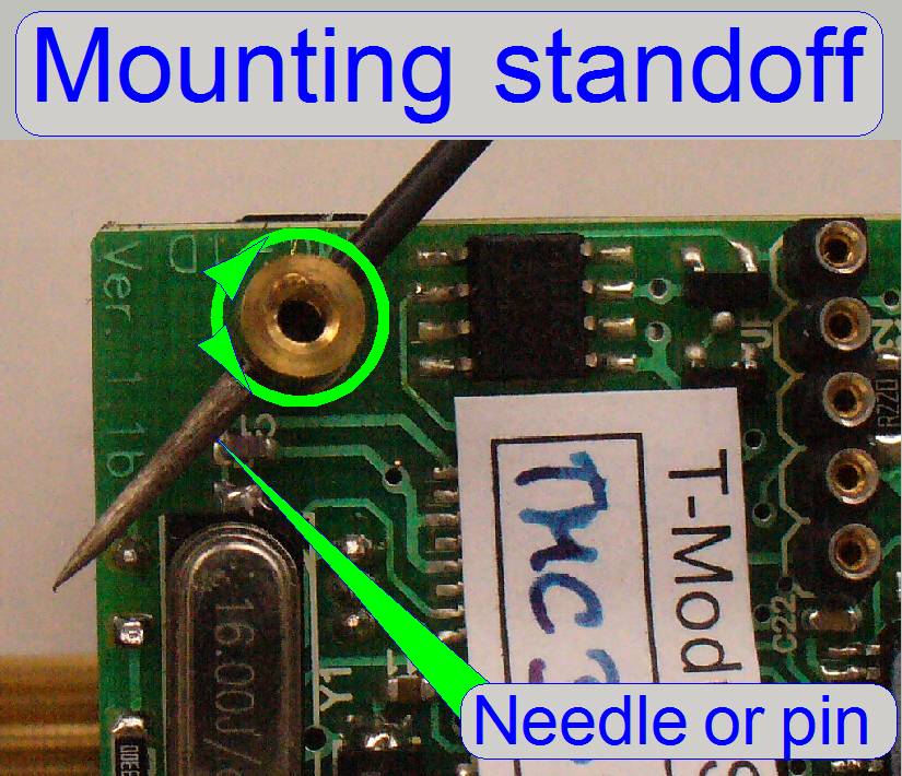
With this solution the PCB position is fixed; by
removing the standoffs, the PCB and the sensors can be moved sideward; the PCB
is then hold only by the soldered motor connection.

Modifications since summer 2016
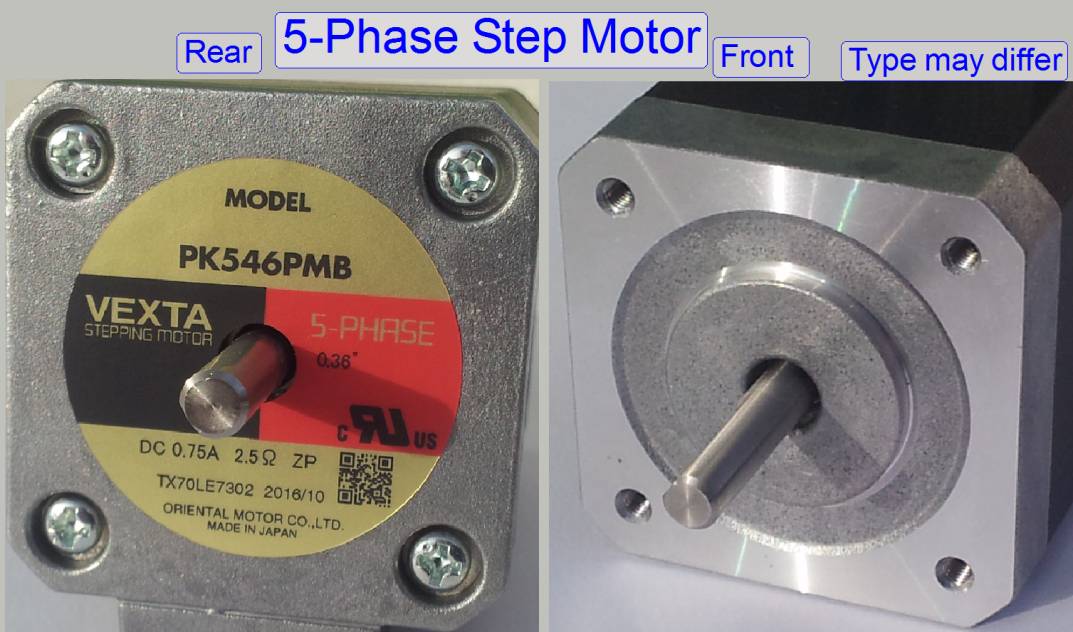
5-Phase stepper motors improving the smoothness of step movements,
reducing so vibration, resonance and noise of the motor, even during the scan
process in progress is this important.
2 types of 5-Phase stepper motors are used since summer
PK544PA single
shaft with a resolution of 500full-steps/revolution; 0.72°/step
PK544PMA single
shaft with a resolution of 1000full-steps/revolution; 0.36°/step
The last letter may be “A” or “B”.
The letter “A” means front shaft only while “B” means front and rear
shaft present.
By using DIP switches inside the motor control unit, the revolution of
1000full-steps is transformed to the number of steps like a 200 or a 400
2-phase full-step motor uses.
The conversion logic (HW and firmware together) transforms the 5-phase
rotor revolution of 1000full-steps (or 500full-steps) into 3200µ -steps
(200full-steps/revolution) or into 6400µ-steps (400full-steps/revolution)
respectively.
· Today 5-Phase
stepper motors with a rotor revolution of 1000full-steps are preferred in
S_M_D_II-type scanners.
· Only the Y-motor
has a rear shaft also.
Construction of the motor unit
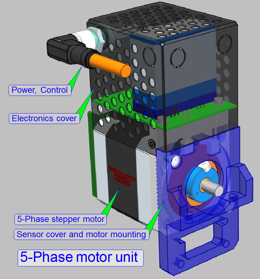
5-Phase stepper motors are implemented into the focus unit
(6400micro-steps/revolution), and the X- and Y-stage unit
(3200micro-steps/revolution).
For the user the 5-phase motor uses the same step resolution (after
transformation) as required for the traditional X-Y-stage unit.
· The focus unit’s
traditional rotor resolution of 3200micro-steps/revolution is now increased to
6400micro-steps/revolution; so focusing of slides with a thickness of 1.2mm
becomes also possible.
Watch video: 5-phase motor unit
5-phase motor
unit construction
Sensors
Home1 and Home2
Modifications are made mainly on the motor axle’s gear wheel and the
sensor Home1.
The sensor Home1 foil disc is replaced by a metal half disc and this is
hold by a bolt, driven into the motor axle’s gear wheel clamp.
- With this
solution, relations between the sensors Home1 and Home2 are always
constant
The working principles of the sensors are not changed.
![]() working
principle of the sensors Home1 and Home2
working
principle of the sensors Home1 and Home2
Watch video: Sensors Home1,2 and Home1

- The working
principle of the sensors Home1, 2 is not modified, only the physical
construction is modified.

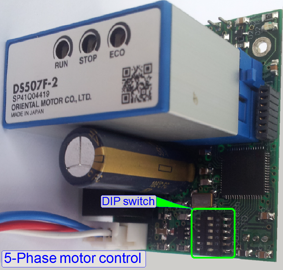
5-Phase stepper motors requiring different drive electronics than the
2-Phase stepper motor.
The manufacturer of stepper motors offers the appropriate motor driver
also as a compact driver module (DS507F-2).
- This driver
module controls the stepper motor in micro-stepping mode.
To drive different kind of motors and to set special conditions,
DIP-switches are used.
In traditional 2-phase stepper motor controllers the address of the
control unit was programmed into the controller, so address modifying was
required if the motor (controller) was exchanged.
- In the new
solution, address programming into the controller is no longer required,
the motor address can be set now via DIP-switches, found on the motor controller
board.
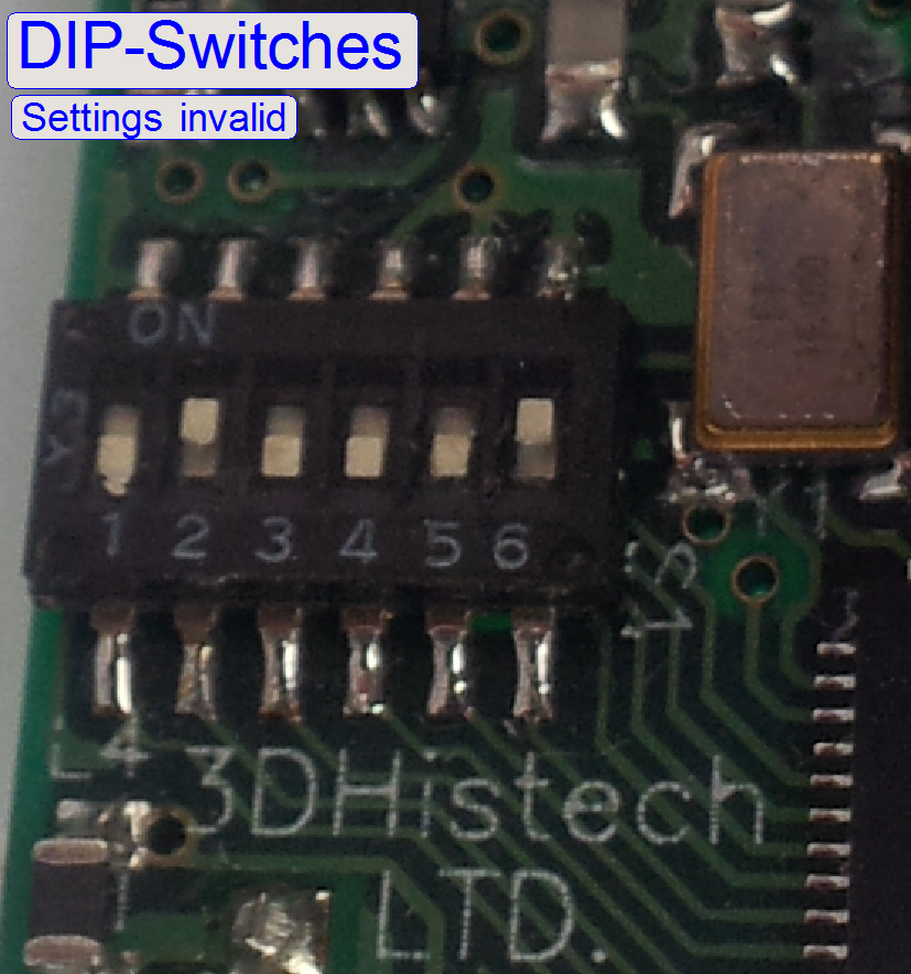
The DIP-switches are used to parameterize the motor control and to adapt
the rotor full-step resolution.
Switch positions 1-4
Four switches are used to define the motor address in binary form.
We know that in S_M_D-type scanners max 16 units are addressable over
the internal I2C bus; the addresses are coded from 0 to 15.
Please remember
- X-motor has
the address 03,
- Y-motor has
the address 04 and
- Z-motor has
the address 05.
Depending on the task of the motor, the appropriate controller address
is coded here in binary form.
 Switch position 5
is used to set the number of full-steps/revolution of the connected
motor or in other words, the rotor’s movement in degrees/full-step.
ON-state: 1000full-steps/revolution
or 0.36°/ full-step
OFF-state: 500full-steps/revolution
or 0.72°/ full-step
- Check the
value for the connected motor and set the DIP-switch into the required
position!
Switch position 6
is used to set the number of full-steps/revolution to be emulated
(required).
ON-state: 400full-steps/revolution; for focus unit
OFF-state: 200full-steps/revolution; X- or Y-stage unit
- Verify the
implementation of the motor unit and set the DIP-switch into the required
position!
X-motor
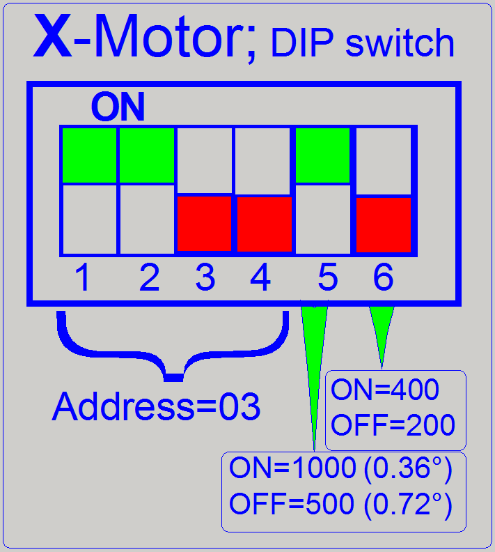
DIP-switches
Address=03
|
1 |
2 |
3 |
4 |
5 |
6 |
|
ON |
ON |
OFF |
OFF |
ON |
OFF |
Setting of Switch 5 is true, if a motor with 0.36°/full-step resolution
is connected.
Read settings as:
The address of the motor controller is 03, this means X-motor; a 5-phase
motor with a resolution of 1000full-steps/revolution is connected and this
resolution will be transformed into 200full-steps/revolution.
Y-motor
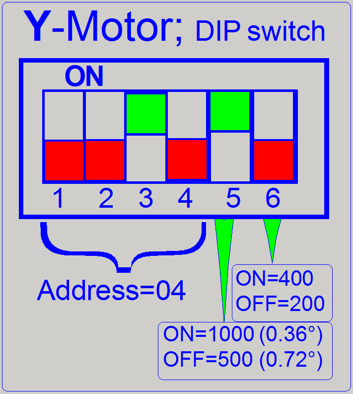 DIP-switches
Address=04
|
1 |
2 |
3 |
4 |
5 |
6 |
|
OFF |
OFF |
ON |
OFF |
ON |
OFF |
Setting of Switch 5 is true, if a motor with 0.36°/full-step resolution
is connected.
Read settings as:
The address of the motor controller is 04, this means Y-motor; a 5-phase
motor with a resolution of 1000full-steps/revolution is connected and this resolution
will be transformed into 200full-steps/revolution.
Z-motor
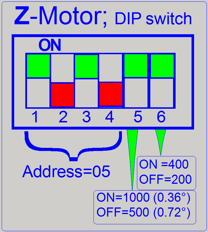 DIP-switches
Address=05
|
1 |
2 |
3 |
4 |
5 |
6 |
|
ON |
OFF |
ON |
OFF |
ON |
ON |
Setting of Switch 5 is true, if a motor with 0.36°/full-step resolution
is connected.
Read settings as:
The address of the motor controller is 05, this means Z-motor; a 5-phase
motor with a resolution of 1000full-steps/revolution is connected and this
resolution will be transformed into 400full-steps/revolution.
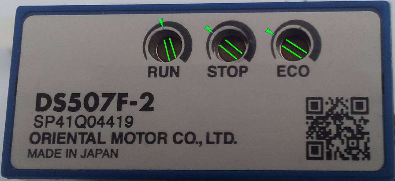
Independent of the motor implementation as X-, Y- or Z-motor, please
check or set the position of the appropriate potentiometer in the stepper motor
driver module as shown on the right.
- Because the
correct setup of the current requires special setup tools, and these are
mostly not available in the field, the technician should check the
position of the potentiometer visually.
- Drive the
potentiometer only, if extremely deviation exists.
Run
This potentiometer defines the maximal current during
starting rotor drive, until the full speed is reached and the breaking current,
until the rotor stops.
- The potentiometer is set a bit before the HALF
position
Stop
This potentiometer defines the current during standstill
operation; the rotor is not moving but the coils are energized.
- The potentiometer is set a bit after the first
QUARTER position, see on the right.
ECO
After the full
speed of the rotor is reached, the rotor is running with this current in full
speed.
Micro-step: The
STOP potentiometer sets the ratio of standstill current to the motor operating
current. In ECO drive mode, the standstill current becomes the discounted value
to the ECO current.
- The potentiometer is set a bit after the first
QUARTER position, see on the right.
More details can be found in: DS507F-2;
Bipolar Microstep Driver (12-24VDC).pdf (stored)
DS_Technical_Information.pdf
(stored)
End