Objective changer;
P250
For technicians and partly for sales managers!
These instructions describe the procedures to install and adjust the
focus unit and the objective changer of the scanner Pannoramic 250. The focus unit
and the objective changer are assembled into a complex unit and these parts can
not be separated in the field. To help resolve problems with the objective
changer or the focus unit a hardware description of the implemented components
and adjustment procedures are added. To increase the manageability, the parts
are discussed separately.
Software relevant settings are based on the software version 1.15.
Contents
 General
- Functional
overview of the focus unit
- Components
and construction
- Adjustments
of the focus part and shutter mechanics
- Adjustments of
the objective changer part
- Dismount or
mount the focus unit with objective changer
- Setup and
define the implemented objectives
- Align
the Objective
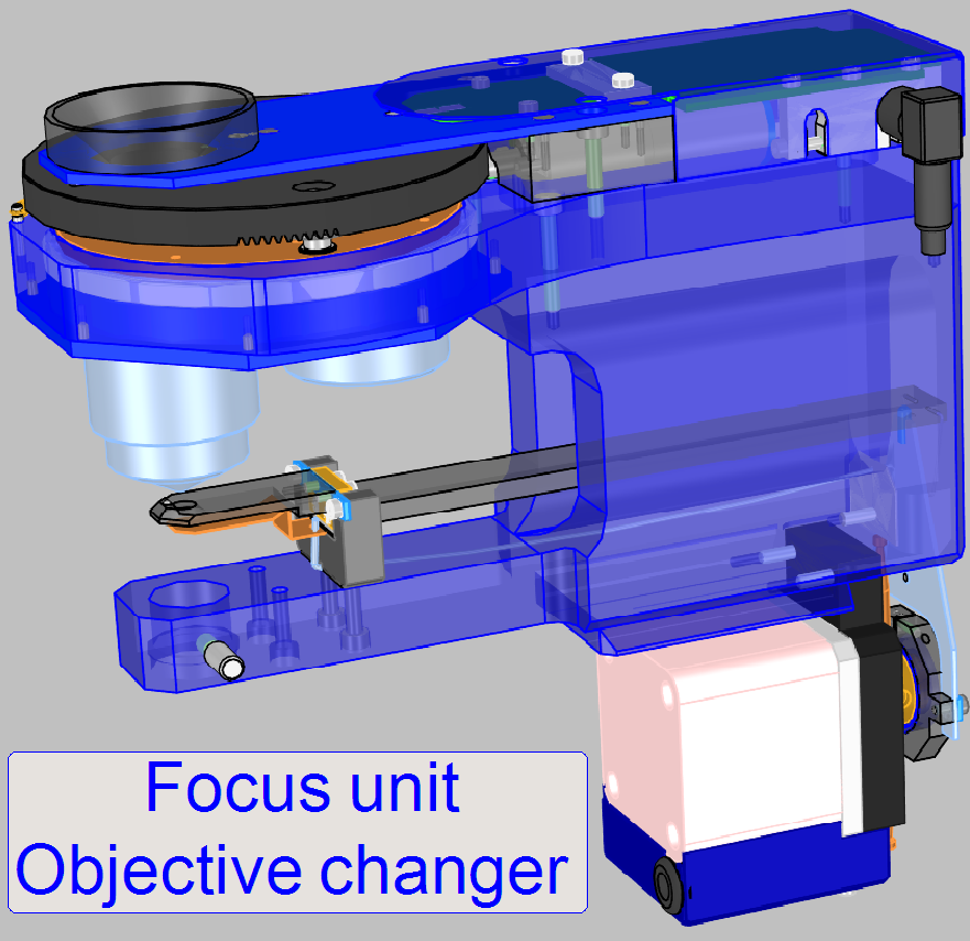
The described
focus unit is a component of the scanner Pannoramic 250 and includes the
following main parts:
The focus unit gives the
possibility of focusing the FOV
(field of view, seen by the scan camera) automatically during the scan process
of the sample.
The objective changer unit is mounted onto the focus unit and allows the
consecutive use of two, preinstalled objectives. The selection or exchange of
the objective is initiated by software before a slide scan session is started.
The movement of the objective holder disc is executed via a DC-motor and the
position is sensed via Hall sensors. Each objective position has a separate
hall sensor, so the software knows always which objective is actually in use.
To guarantees the proper position of the objective in the light path, the final
objective position is fixed via a form-fit mechanism.
The unit was developed for
the use of objectives of the following types:
Plan-APOCHROMAT
20x/0.8 and Plan-APOCHROMAT
40x/0.95
The objective type
“Plan-Apochromat” contains several, special chromatic and spherical corrections
and delivers so an image of very high color trueness with very small spherical
aberration.
If the mechanical dimensions do
not exceed the size of the Plan-APOCHROMAT 40x0.95 type objective, the
mechanical mounting is identical and the focus distance of the objective to the
tissue is not closer then 0.25mm, other kind of objectives can be used also but
it is strongly not recommended! Always check with 3DHISTECH first if a
different objective should be used!
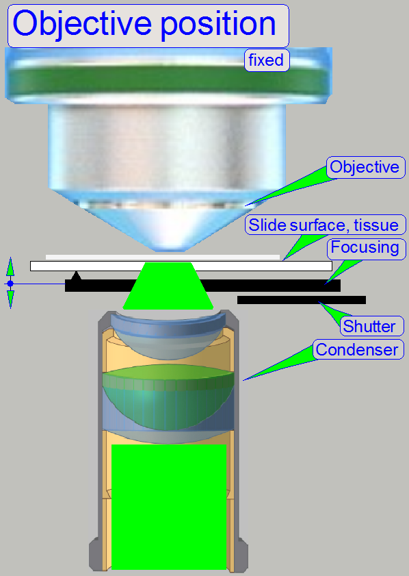
The shutter mechanics covers the
condenser and this way the bright field illumination path is broken during
fluoresce scan sessions. The two commands, “condenser cover off” and “condenser
cover on” are identical with the physical lower and upper hardware limit of the
focus unit.
Automatic scan
In the slide
scan table of the scan program “SlideScanner.exe” you can assign the objective
with which the slide should be scanned. In other words, the objective can be
changed any time between two slide scanning procedures. If the slide scan table
does not contain information about the objective, the scan procedure will be
done with the actual objective.
Remark
By default, the brightfield
scan procedure is always done by the use of the 20x objective; during the
fluorescent scan session can be done with the 20x or the 40x objective
likewise.
 Since the software
version 1.16 the BF scan session may be executed with the 20x or the 40x
objective likewise.
Since the software
version 1.16 the BF scan session may be executed with the 20x or the 40x
objective likewise.
![]() “Upgrade to the
software version 1.16” and “What is new” “Brightfield
scan with the 40x objective”
“Upgrade to the
software version 1.16” and “What is new” “Brightfield
scan with the 40x objective”
Manual scan
The objective can be changed any time, before
the scan procedure is started.
The bus connector provides the
power supply and Data information for the objective changer as well as for the
turret unit via the cable DCJ-1; the
stepper motor cables of the focusing part are connected to the connectors “Z”
of the “X-Y-Z-ND and
Flash” controller.
The
exchange of the focus unit with the objective changer is possible:
- If the
stepper motor or its connection is faulty
- If the DC
motor or the electronics of the objective changer unit is faulty.
- If the shape of
any part is deformed or a part is broken.
- If the focus
unit or the objective changer has any
fault and you are unable to fix it.
Requirements
- Service
program for slide scanners (SlideScannerService.exe)
with actual license file
- Slide scanner
(version 1.15 or higher) and Slide scanner Viewer software
(SlideScanner.exe, SlideScannerViewer.exe) with actual license files
- 1.5, 2.5, 3
and
- A pair of
special wrenches to adjust the objective position
- Hardware and construction
knowledge of the scanner Panoramic 250
Attention: Do not mix the versions of
SlideScanner.exe and SlideScannerService.exe! Always use these programs with
the same version number. Otherwise the SlideScannerService.exe program could
produce unwanted results and SlideScanner.exe does not work correctly or even
freeze!
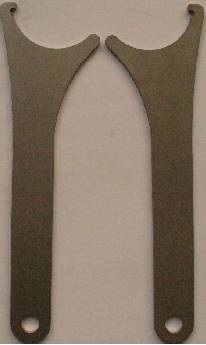
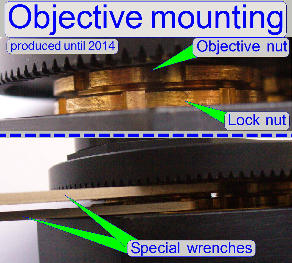
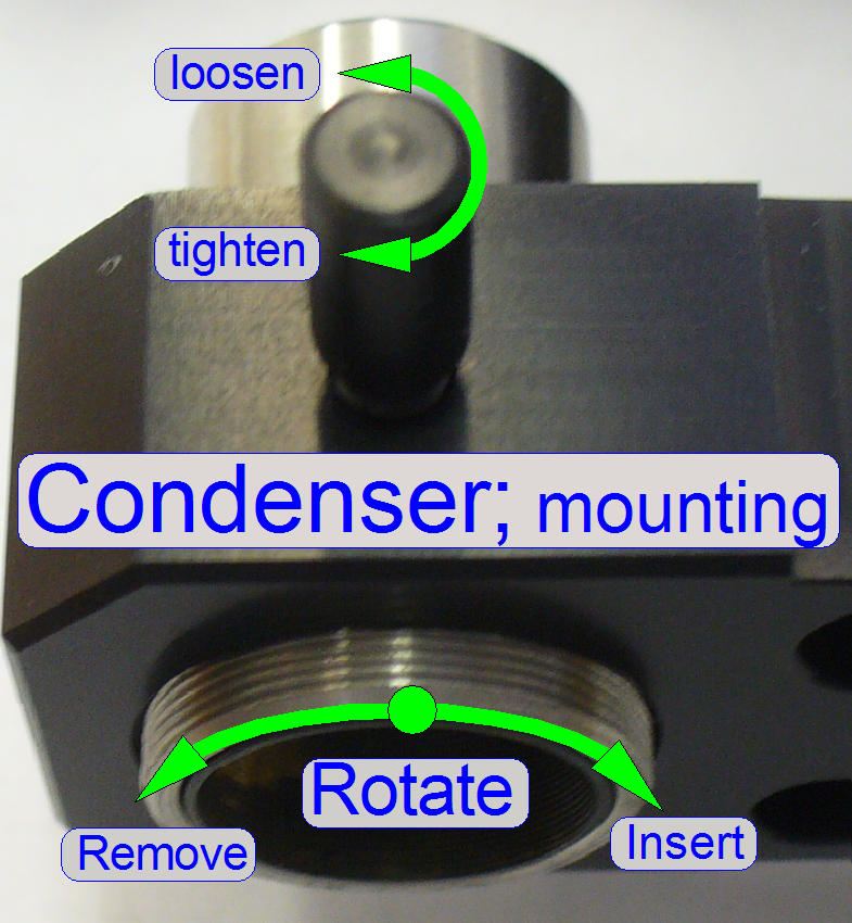
The objective nut and
the lock nut of the objective mounting are handled by using the two
wrenches shown on the right; these are delivered with the scanner Pannoramic
250 until spring of 2014.
- To fix the
objective position, hold still the objective mounting nut with one wrench
and loosen or tighten respectively the lock nut with the other wrench.
Configure the objective changer unit
Since the software version 1.15 the units of the scanner are configured
in the file “MicroscopeConfiguration.ini”, section [Microscope].
The actual version of the objective changer unit in the scanner
Pannoramic 250 is “ObjectiveChangerType=OC_2Pos”.
· The
path of the file MicroscopeConfiguration.ini, in the software version with the
operating system Windows® 7 is:
C:\ProgramData\3DHISTECH\SlideScanner\MicroscopeConfiguration.ini
[Microscope]
SerialNumber=xxxxx
MicroscopeType=3DMic9
ScanCameraType=
PreviewCameraType=CVrmc_m8_pPro
BarcodeReaderType=PreviewCamera
LoaderType=SL_9Mag_25Slide_Sensor_Vertical
CameraChangerType=CC_3DH_2Pos
ReflectorTurretType=RT_3DH_10Pos_Belt
BrightfieldLightSourceType=FlashLight2010
ObjectiveChangerType=OC_2Pos
ObjectGuideXYZType=OGXYZ_FLASH3
FlashUnitType=FlashUnit_Type2
NDFilterType=NDType2
PreviewLightType=PreviewLightUnitType_Type2
PowerSwitchBoardType=PowerSwitchBoard_Type1
If a different value is used
for the objective changer unit, may be the unit is not recognized or is working
wrong!
Functional
overview of the focus unit
Physically, the focus
position is defined by the distance of the objective to the tissue. If the
tissue is in the focus of the objective, a sharp image is seen by the camera. Because
the tissues are different from each other in thickness, and the thickness can
change inside the same tissue also, the focus position must be checked and
corrected always, during the scan procedure.
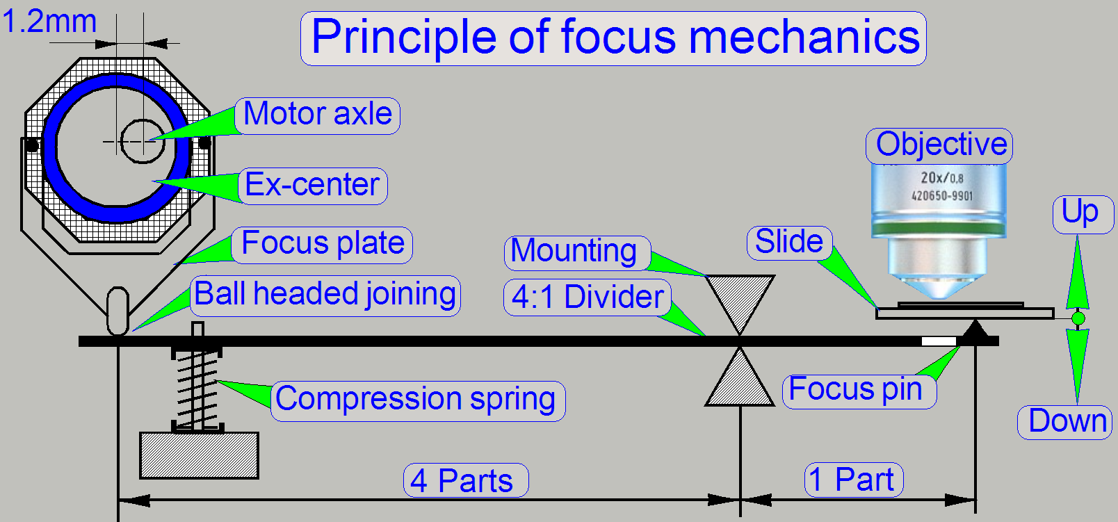
- In Pannoramic scanners, as well as in the
P250, the real focus position is found by moving the slide toward or away
from the objective via the focus pin.
- The focus position is influenced by both,
the fixed (adjustable) objective position and the actual position of the
focus pin.
Furthermore, if the slide as
well as the objective will be changed, the specimen holder must be moved away
from the objective to avoid collision.
If the shutter is changed
from shutter off to shutter on or vice versa, the specimen holder is moved to a
position where the focus pin is not in connection with the slide or the
specimen holder. This way, the distance between specimen holder (cover slip)
and objective is not affected if the ex-center crosses the upper peak of the
sine wave.
During all these actions,
except focusing, the objective must be protected against touching the cover
slip and the focus pin and 4:1 divider must be protected against overstraining.
This is realized by the focus unit, with the different positions of the focus
pin and 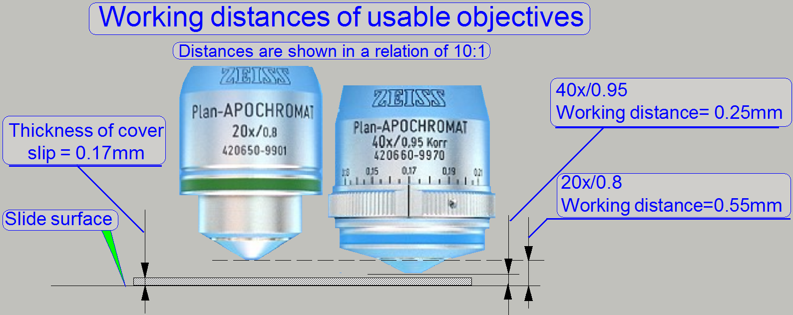 the positions of the specimen holder.
As
you can see, the gaps between cover slip and objective are very small,
especially if the objective Plan-APOCHROMAT
40x/0.95 is used.
Because both objectives can
be used without adjustment of the objective position after exchange, the
previously developed focus unit (the focus unit for SCAN,
![]() “Optical path and
Field Of View”
“Optical path and
Field Of View”

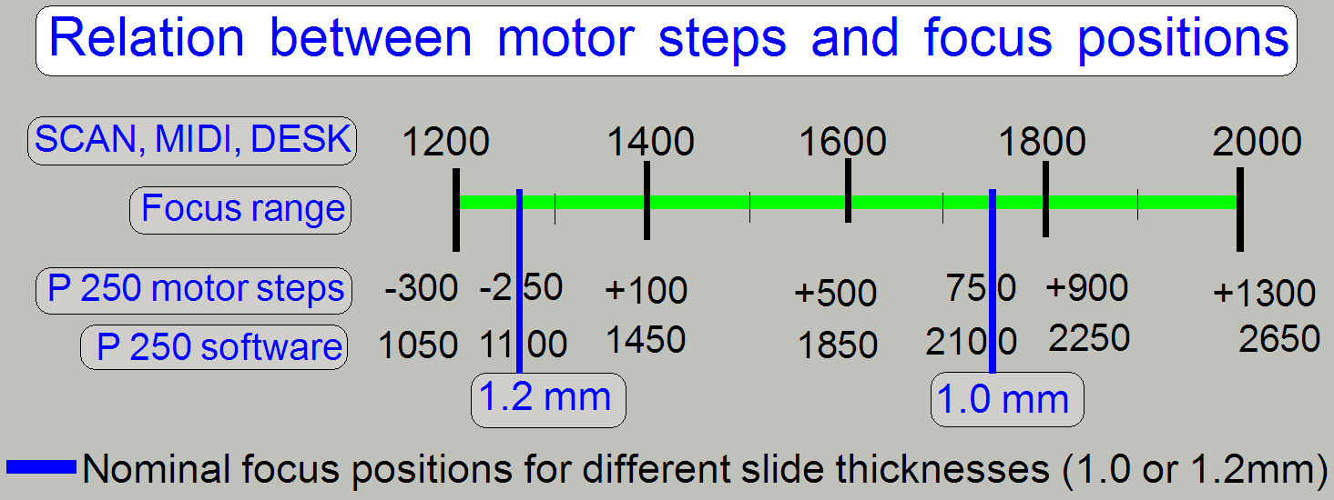
On the scale of the 40x
objective, the nominal thickness of the cover slip should be selected.
- If the real thickness of the cover slip
differs from the selected or adjusted value, the quality of the scanned
FOV may be reduced!
 In Pannoramic type
scanners the objective is mounted into the middle of the focus range, offered
by the movement limits of the focus pin during focusing.
In Pannoramic type
scanners the objective is mounted into the middle of the focus range, offered
by the movement limits of the focus pin during focusing.
- It is very important, that the objective
position is adjusted well; otherwise, if the objective position does not
match the focus range, offered by the focus pin movement range, a focused
camera image can never be produced!
- Because the slide thickness can vary from
0.95 to
![]() “Adjust the
objective position”.
“Adjust the
objective position”.
The slide is hold in the specimen
holder (not shown; see the X-Y-Stage). To achieve a parallel movement of the
slide in relation to the objective, the specimen holding mechanics contains a
parallelogram. This guarantees the position of the tissue to be always
perpendicular to the optical axis during focusing. The specimen holder has a
mechanical preload, so the slide has always a connection to the focus pin,
except during a shutter on qr off operation.
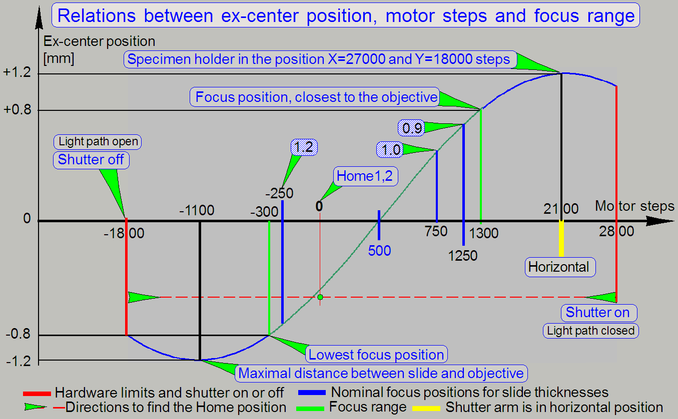
To avoid collision of the
objective with the slide during the “shutter on” command, the X-Y-stage is
moved to a place (X=27000 and Y=18000 steps) where the focus pin is not in
connection with the slide or the specimen holder; otherwise the 40x objective
would collide with the slide or specimen holder.
This principle is used also
if an objective exchange procedure is in progress with the objective changer.
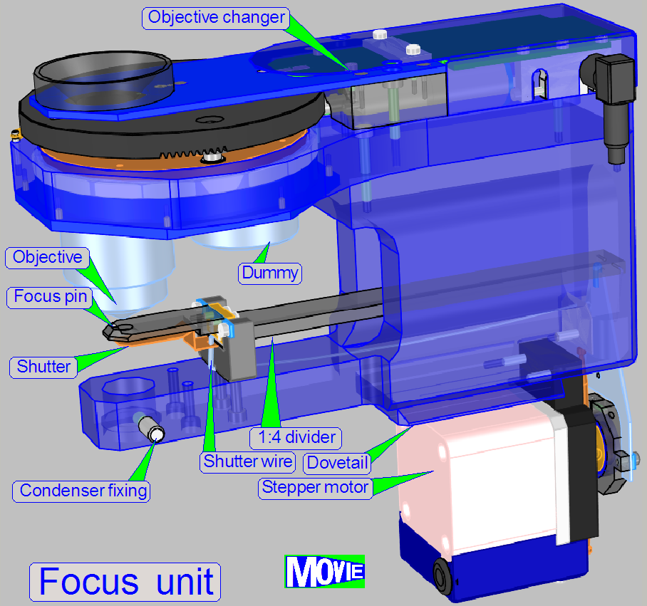
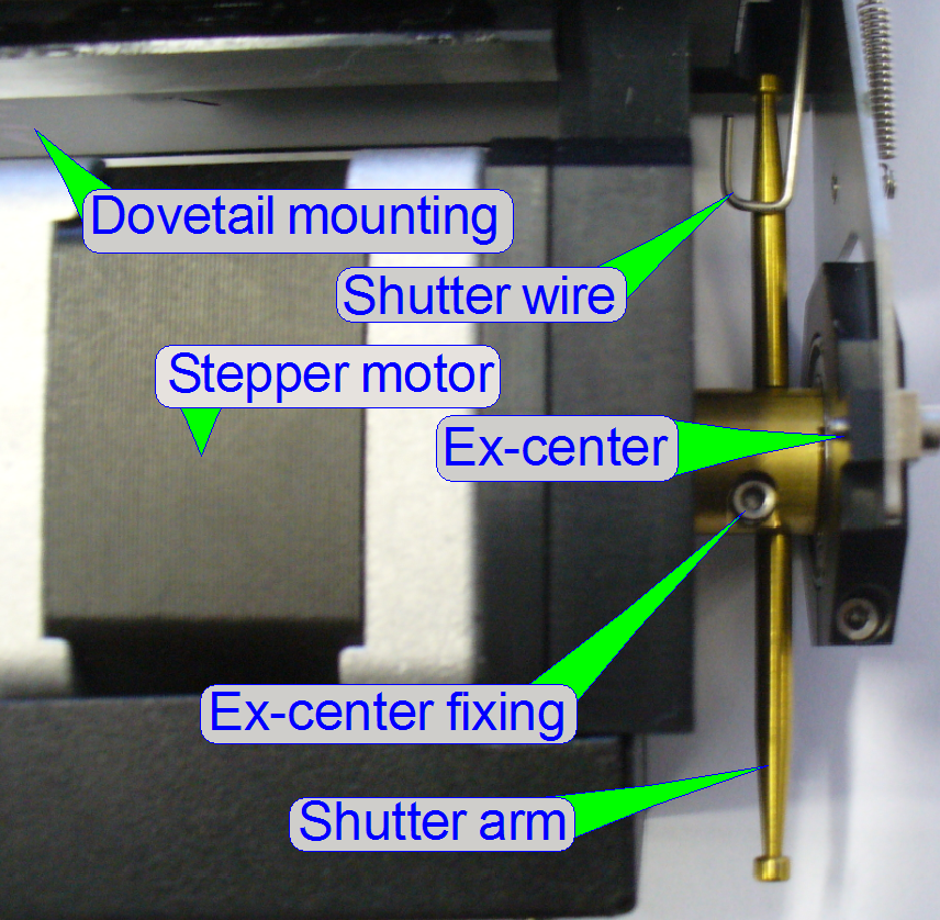
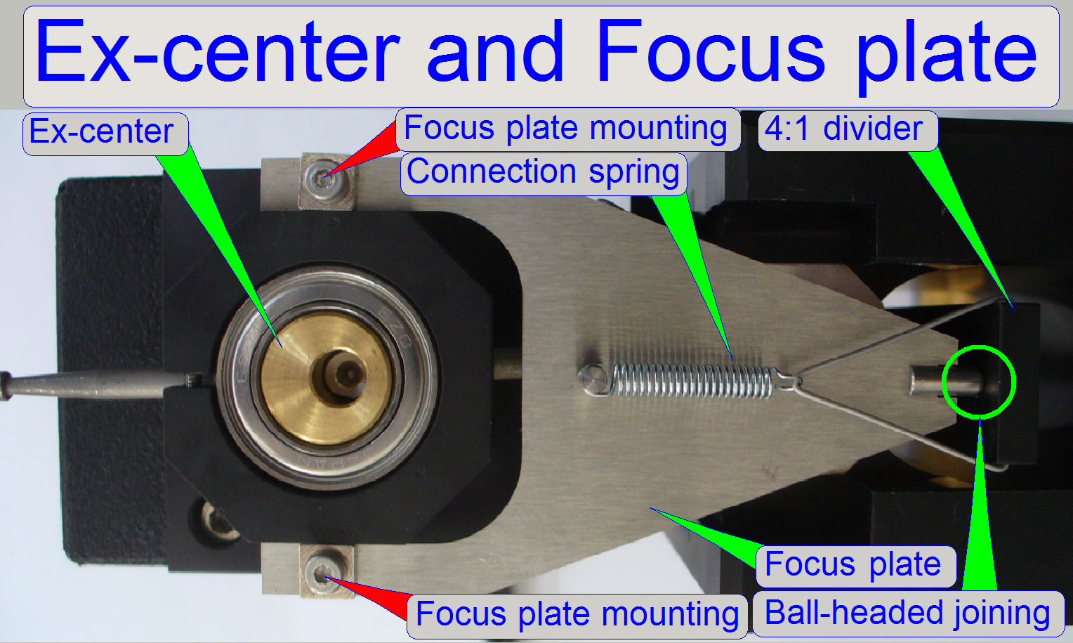
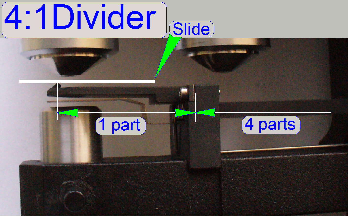
The focus pin is moved by a
stepper motor via an ex-center and a 4:1 divider. The resolution of the stepper
motor with 6400 steps per revolution, the characteristics of the ex-center and
the 4:1 divider allows a very fine resolution of the focus steps and so tissue
focusing.
 The focus position
of the FOV is found, if the camera sees a sharp image. To reach this, the scan
camera takes images in different positions of the entire focus range and the
software finds the best focus interval. When this interval is found the real
focus position is found by iteration of the interval.
The focus position
of the FOV is found, if the camera sees a sharp image. To reach this, the scan
camera takes images in different positions of the entire focus range and the
software finds the best focus interval. When this interval is found the real
focus position is found by iteration of the interval.
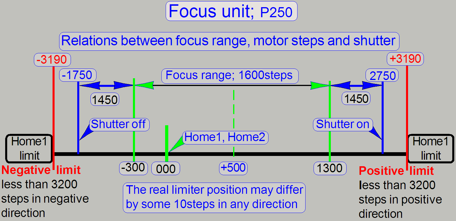
In opposite to the DESK,
The Home position of the entire
mechanics is situated inside the focus range. Because the number of steps never
exceeds the direction limit for Home1 (the number of steps is always less then
3200 steps in each direction) the home position is always found within Home1
only. The option Home2 will never be executed during normal scan operations and
is used during system integration only or before the ex-center fixing bolt will be tightened
(if mechanical adjustments are done on the ex-center). In this case, the
mounting of the ex-center starts after a Home1,2 execution. This solution is
important for protecting the 40x objective.
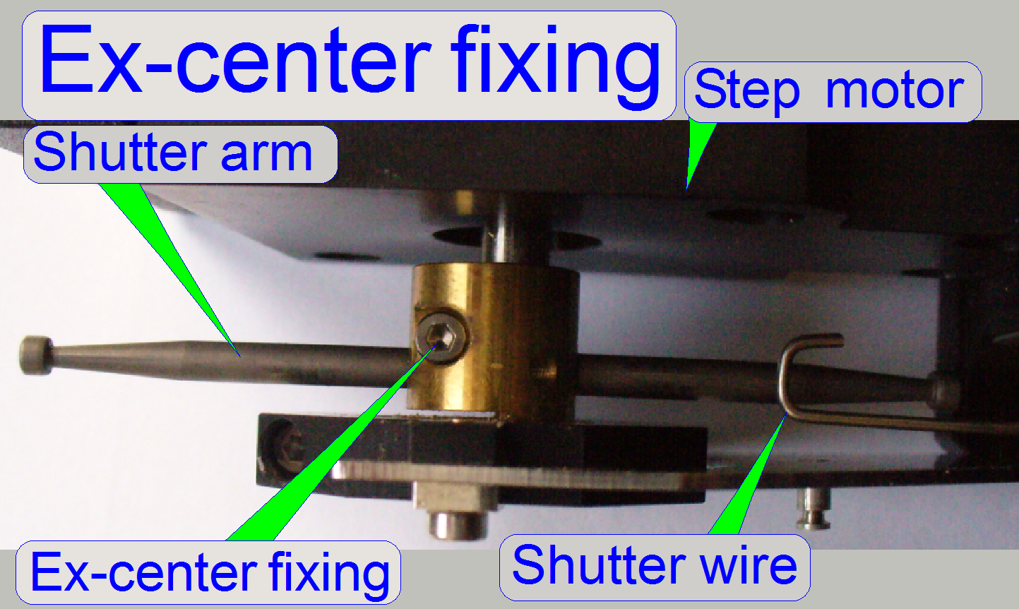
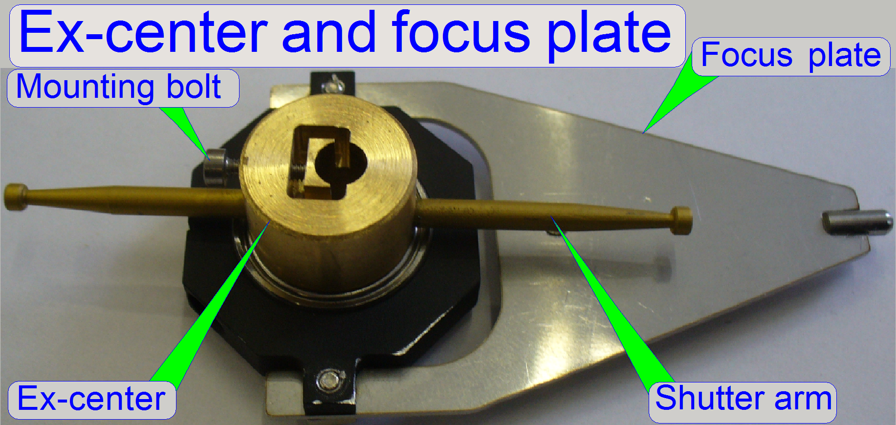
Shutter arms are in
horizontal position
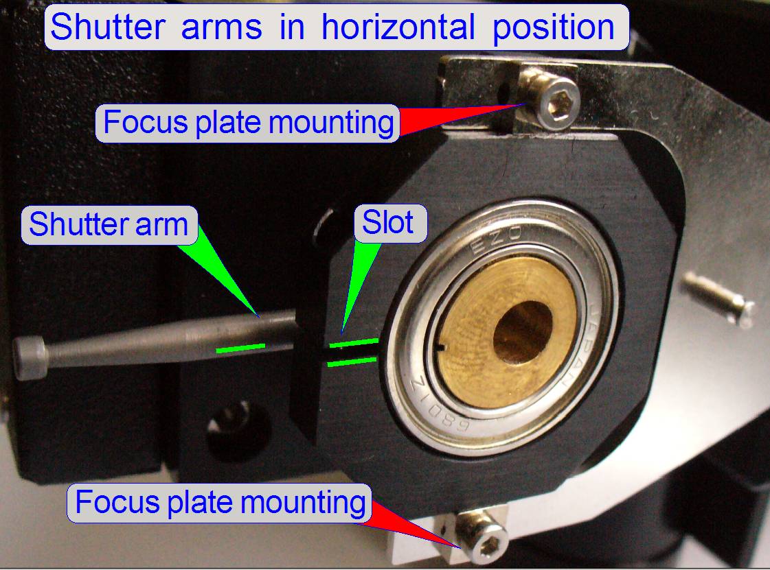
This is a special position
for adjusting the physical ex-center position on the motor axle. This adjustment
defines the focus range; the sine wave crosses the X-axis at 500 motor steps
(see above).
- Use the position of the slot in the
ex-center and focus plate mounting to adjust the shutter arms into the
horizontal position.
Hardware
limits; shutter on and off
 By the use of two
shutter arms, one for shutter on, the other for shutter off operation, the
hardware limits could be held inside the direction limit for Home1 (less then
3200 steps in each direction). The hardware limits will be reached only during
shutter on (CondenserCoverOn = BF light path closed, fluoresce scan) or the
shutter off (CondenserCoverOff = BF light path opened, brightfield scan)
procedure. To prevent the touching of the 40x objective during the shutter on
procedure, the action is executed at a special specimen holder position, where
the focus pin is guaranteed between the specimen holder and the slide. This
position is X= 27000 steps and Y=18000 steps. This way, the specimen holder
practically does not move, during the ex-center crosses the upper peak of the
sine wave, because there is no connection between focus pin and slide or
specimen holder. Please take this into
account if you are working with the service program!!
By the use of two
shutter arms, one for shutter on, the other for shutter off operation, the
hardware limits could be held inside the direction limit for Home1 (less then
3200 steps in each direction). The hardware limits will be reached only during
shutter on (CondenserCoverOn = BF light path closed, fluoresce scan) or the
shutter off (CondenserCoverOff = BF light path opened, brightfield scan)
procedure. To prevent the touching of the 40x objective during the shutter on
procedure, the action is executed at a special specimen holder position, where
the focus pin is guaranteed between the specimen holder and the slide. This
position is X= 27000 steps and Y=18000 steps. This way, the specimen holder
practically does not move, during the ex-center crosses the upper peak of the
sine wave, because there is no connection between focus pin and slide or
specimen holder. Please take this into
account if you are working with the service program!!
![]() “How
to define hardware limits”
“How
to define hardware limits”
In earlier developed scanner
systems (DESK,
Because the resolution of the
motor is increased by twice (1 revolution of the motor axle is done in 6400
steps), the focus range is now 1600 steps, in the P 250.
Because the focus range is
physically counted from -300 steps to +1300 steps, and negative numbers as
focus position are unusual, the entire focus range is shifted in the software
to the focus range from 1050 to 2650; add to the physical step number
1350.
In the Pannoramic 250: SW focus position = HW stepper motor
position + 1350.
 Because the specimen holder
of the scanner P250 can hold slides with a thickness of
Because the specimen holder
of the scanner P250 can hold slides with a thickness of
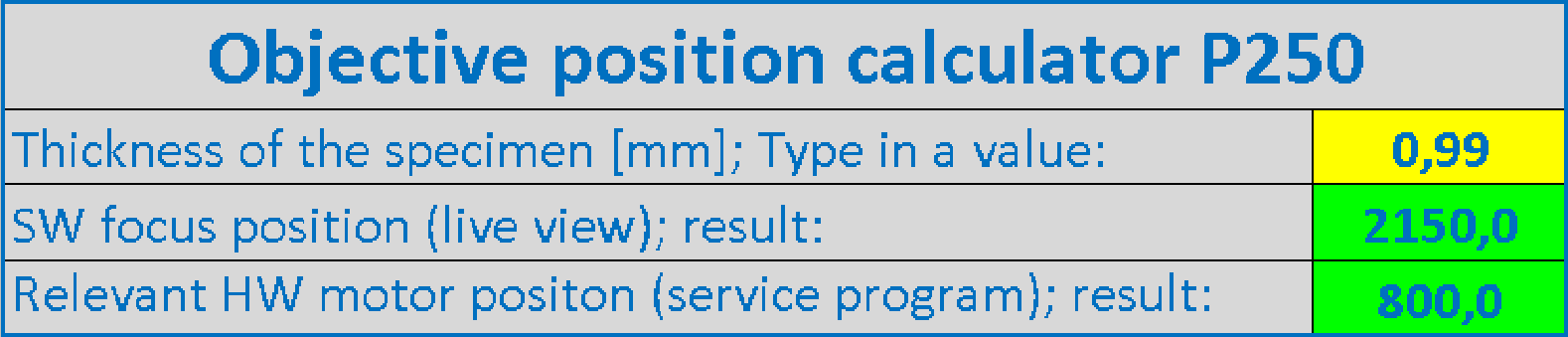
- Measure the thickness of the slide with
tissue to be used (but without the cover slip); use the caliper.
- Use the “Objective position
calculator” on the right to find the nominal focus position.
- Insert the measured slide into the specimen
holder and set the appropriate (calculated) focus position in the live
view of the program SlideScanner.exe
- Adjust the objective position to the preset
focus position until a focused image can be seen in the live view.
![]() “Check or
adjust the objective position”
“Check or
adjust the objective position”
Components and mechanical construction
All stepper motor relevant
information, like step number and direction; go to Home1,2 or shutter on and
off and the state of the sensors Home1 and Home2 are transferred via the
stepper motor cables; these are connected to the “Z” connectors of the “X-Y-Z-ND-Flash”
controller unit.
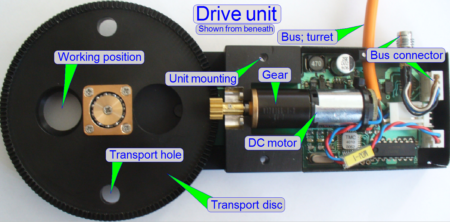
In opposite to the DESK,
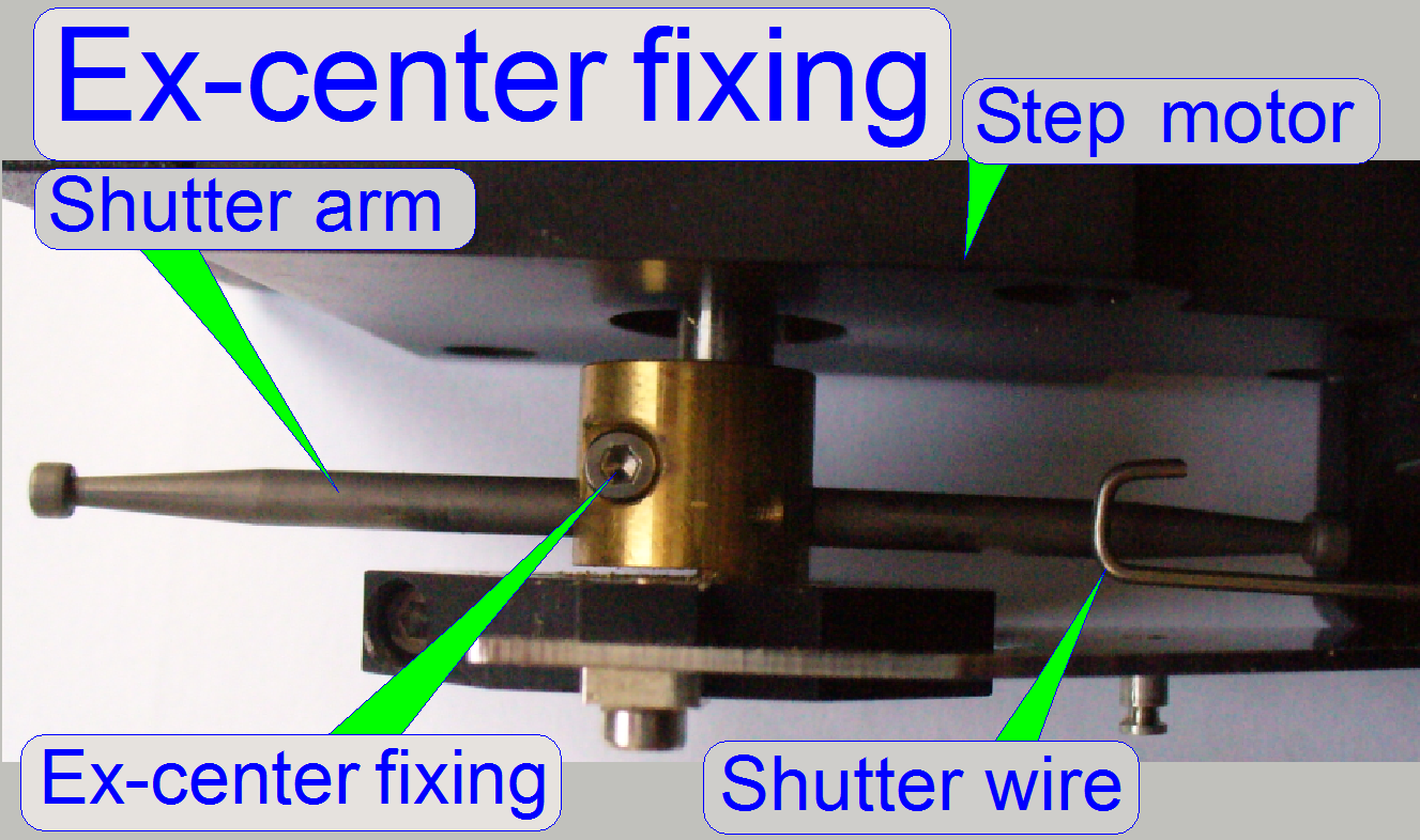
On the ex-center mounting the
two shutter arms are situated for the shutter off and shutter on operation; so
the focus motor can not do a full revolution in any direction.
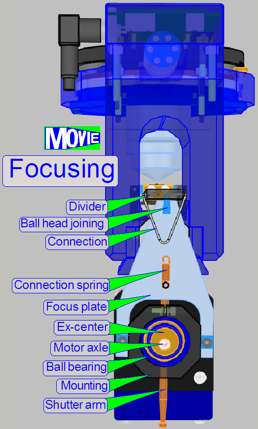
 The motor axle of
the stepper motor rotates the ex-center on which the focus plate is mounted and
this moves the 4:1 divider.
The motor axle of
the stepper motor rotates the ex-center on which the focus plate is mounted and
this moves the 4:1 divider.
Attention
 The mountings of the
focus plate should not be loosened; here the position of the focus plate and so
the position of the 4:1 divider and the position of the focus pin is adjusted!
The mountings of the
focus plate should not be loosened; here the position of the focus plate and so
the position of the 4:1 divider and the position of the focus pin is adjusted!
Because the movement of the
focus pin is very small, the adjustment of the focus pin position is delicate; the focus plate mounting bolts position
must not be altered.
·
The
adjustment of the focus pin position can be done in the factory only!
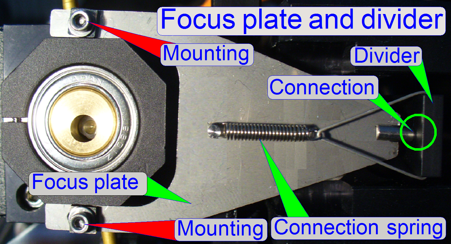 The connection between
focus plate and divider is realized with a ball-headed joining because the
ex-center does an up-down and additionally a left-right movement.
The connection between
focus plate and divider is realized with a ball-headed joining because the
ex-center does an up-down and additionally a left-right movement.
The connection spring ensures
a slippage-free connection between focus plate and 4:1 divider.
The connection spring ensures a
slippage free connection of the ball headed joining.
Attention
The mountings of the focus
plate should not be loosened; here
the positions of the focus plate, the position of the 4:1 divider and so the
position of the focus pin are adjusted!
Because the movement of the
focus pin is very small, the adjustment of the focus pin position is delicate; the focus plate mounting bolts position
must not be altered.
·
The
adjustment of the focus pin position can be done in the factory only!
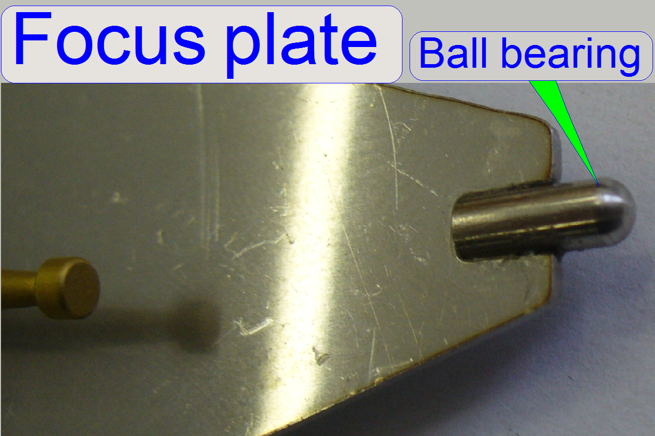 The bearing of the
4:1 divider and the ball-headed pin of the focus plate eliminates the unwanted
left or right movement.
The bearing of the
4:1 divider and the ball-headed pin of the focus plate eliminates the unwanted
left or right movement.
 On the other end of
the 4:1 divider the focus pin is realized. The focusing of the tissue is done
by moving the focus pin toward or away from the objective; the mechanical
construction allows a focus pin movement of
On the other end of
the 4:1 divider the focus pin is realized. The focusing of the tissue is done
by moving the focus pin toward or away from the objective; the mechanical
construction allows a focus pin movement of
The objective changer part of
the focus unit consists of:
- The drive unit with the
transport disc, the DC motor and the control electronics.
- The electronics cover and
- The objective changer mechanics with the objective disc,
the form-fit mechanism
and the objective
holding nuts.
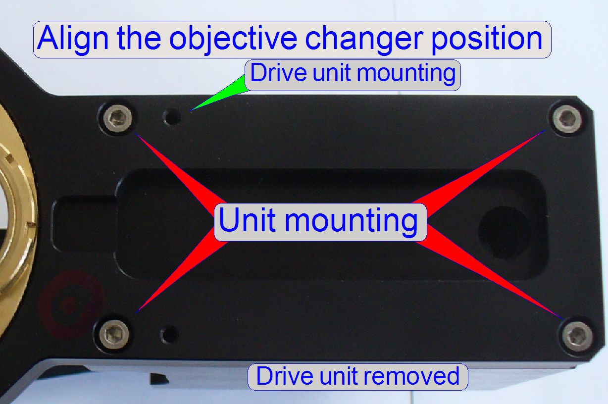
Important
The drive unit can be
separated from the objective changer mechanics unhesitatingly, but do not remove the objective changer
mechanics from the focus part; see “Align the
objective into the optical axis” first!
Functional overview and construction
The following chapters,
concerning the objective changer are true for the “
Drive
unit (from top)
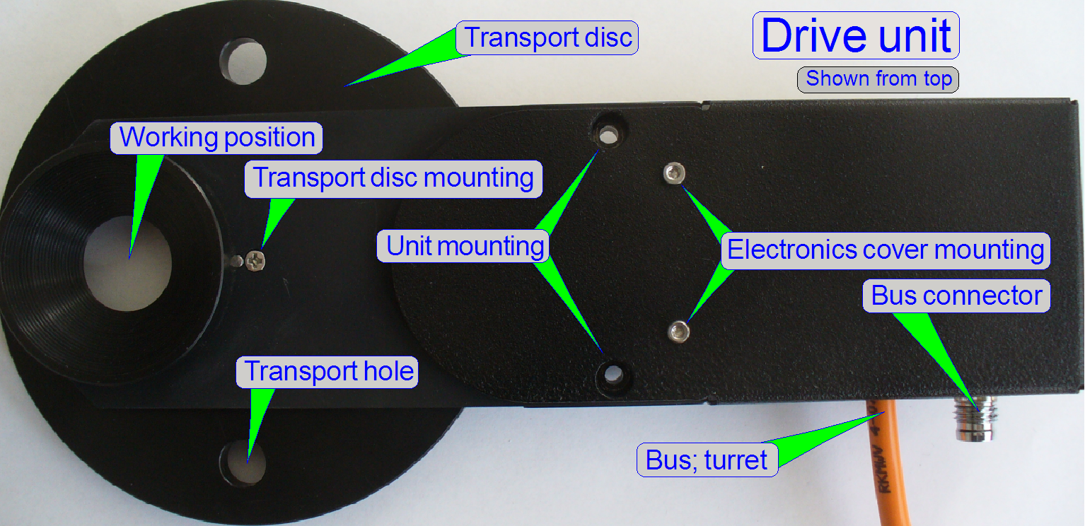
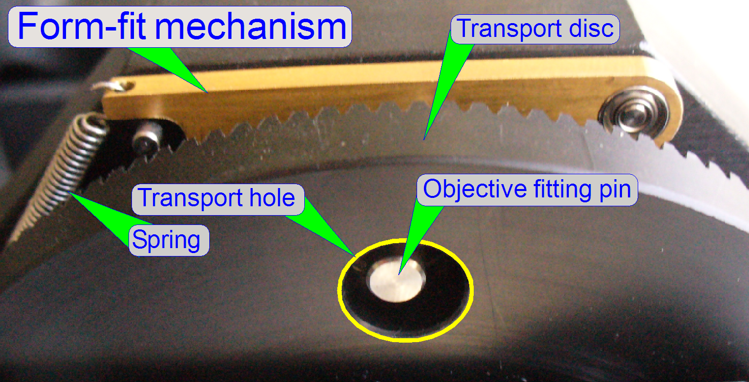
The transport disc is rotated
by the DC motor; always in the mathematical positive direction, if we are
looking onto the objectives (during normal work).
The transport disc moves the
transport pins situated in the transport holes, by a half revolution.
Just before the working
position of the objective is reached, the DC motor will be switched off by the
appropriate sensor and the final movement, into the exact working position
(into the optical axis), is done by the form-fit mechanism.
- The transport disc can be rotated manually,
but do it carefully!
- The unit does not need maintenance or
adjustments.
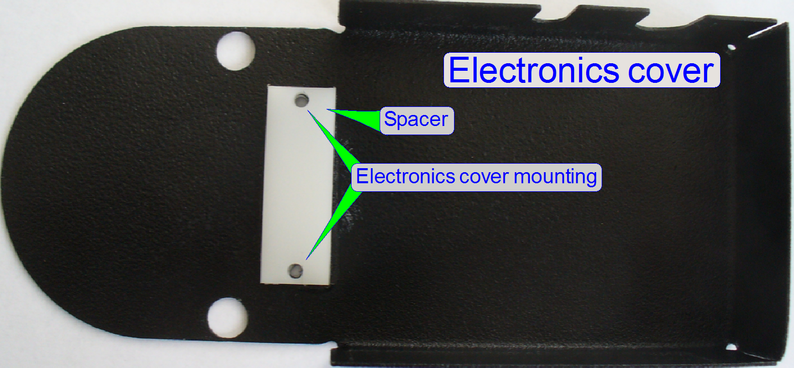
The spacer in the electronics
cover keeps a distance between cover and PCB and avoids so a shortcut in the
electronics.
 The control electronics get its information
via the cable DOJ-1
and the bus connector; the bus is prolonged to the turret unit via the cable FCJ-1.
The control electronics get its information
via the cable DOJ-1
and the bus connector; the bus is prolonged to the turret unit via the cable FCJ-1.
- The address of the
control electronics is 09.
- The objective
changer type is defined in the file
“MicroscopeConfiguration.ini” in the section:
[Microscope]
.
.
.
ObjectiveChangerType=OC_2Pos
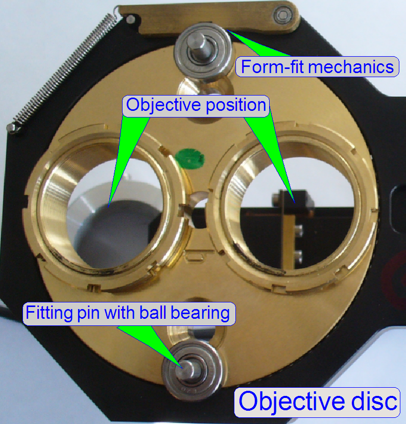
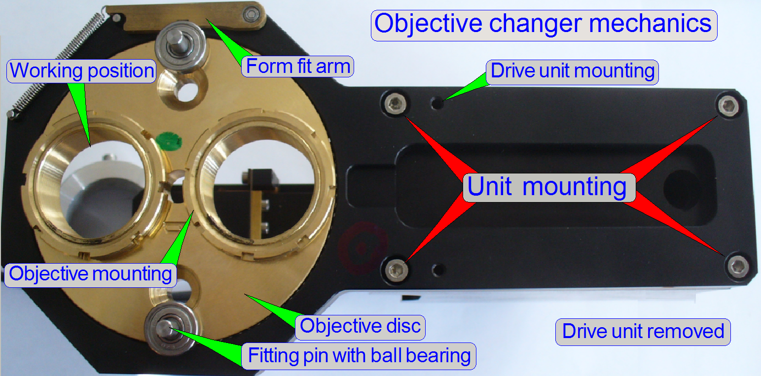 The objective disc holds the
objectives and is driven by the fitting pins.
The objective disc holds the
objectives and is driven by the fitting pins.- The form-fit arm, together
with the ball bearing of the fitting pin guarantees the proper and
constant objective position in the light path, even if the objective has
been exchanged.
- The objective
position can be adjusted with the objective mounting nut and is hold
constant with the lock nut; see also “The objective nuts”.
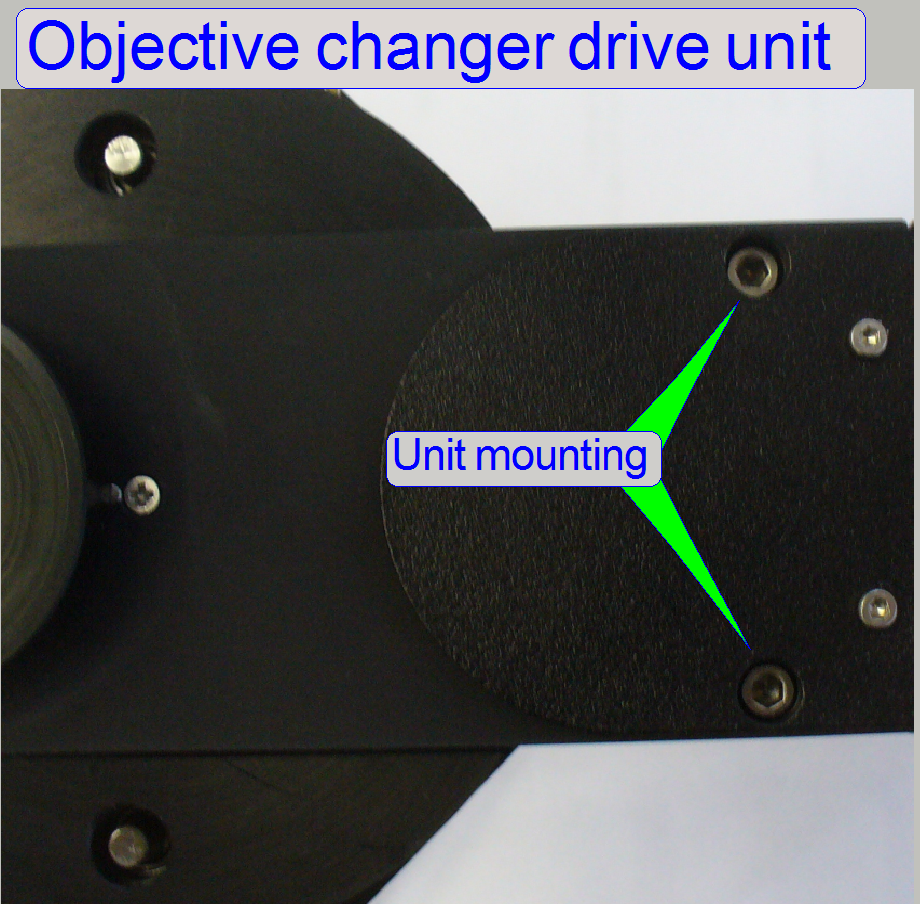
- The unit
mounting of the objective changer mechanics should not be loosened or removed, because the working position
of the objective in relation to the optical axis is adjusted here; see
also “Align
the objective”.
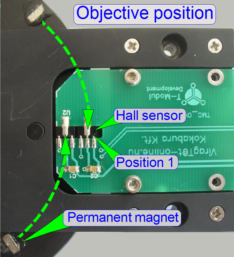
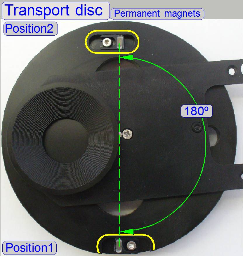
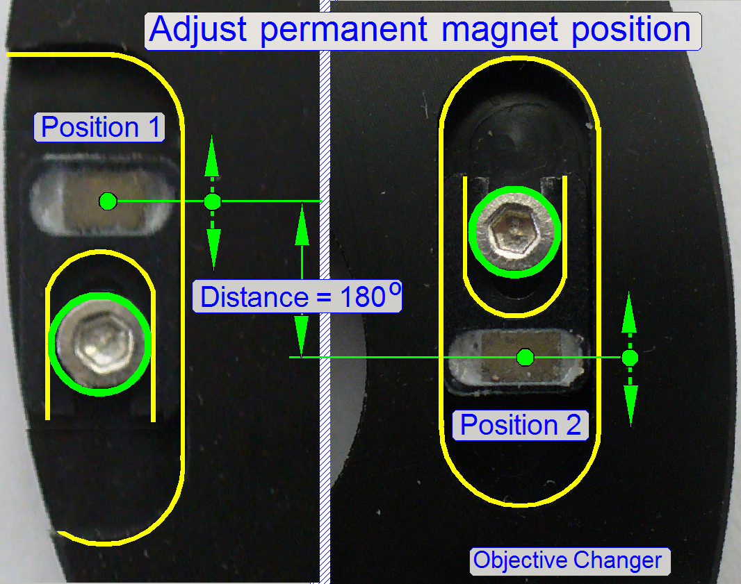
As mentioned above, on the top of the transport disc two permanent
magnets are situated; the distance to each other is exactly 180 degrees (not
shown correctly).
Just before the working
position of the objective is arrived and the dead point of the form-fit
mechanism is even crossed, the permanent magnet arrives over the sensor and
stops so the movement of the transport disc.
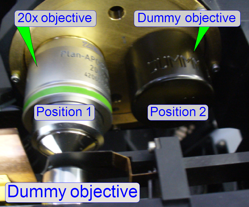
- Each objective (position) has its own
sensor and its own permanent magnet also; the positions are named as
“Objective position
- In the objective position 1 always the 20x
objective has to be mounted; in the objective position 2 the dummy
objective or the 40x objective is situated.
- The objective positions 1 and 2 of the
objective disc are decided, if the drive unit will be mounted; see also “Mount the
objective changer drive unit”
Adjustable permanent
magnet position
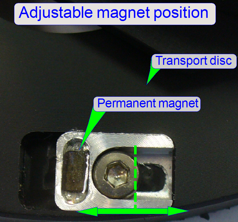
In scanners, manufactured
since June 2013, the position of the permanent magnet is adjustable.
With this solution, and by
adjusting the magnet position, the dead point of the form-fit mechanism can be always
reached surely.
·
If one permanent magnet position is moved backward (or
forward) the permanent magnet in the opposite position should be moved also
backward (or forward) by the same distance!
·
To
reach a correct adjustment, the distance of the permanent magnets to each other
has to be always 180º!!
With this solution, and by
adjusting the magnet position, the dead point of the form-fit mechanism can be
always crossed surely.
![]() “Adjust permanent
magnet position”
“Adjust permanent
magnet position”
Watch video: “P250_Objective change”
·
If one permanent magnet position is moved backward (or
forward), the permanent magnet in the opposite position should be moved also
backward (or forward) by the same distance!
·
To
reach a correct adjustment, the distance of the permanent magnets to each other
has to be always 180º!!
Adjust permanent magnet position
With the service program
rotate the Transport Disc in forward direction.
If the motor is switched off,
the form-fit mechanics should act and the final objective position should be
reached surely.
Otherwise, a small gap should
also exist between transport hole and transport pin, if the objective stays in
the optical axis.
Check this behavior in both
objective positions several times with the service program!
Watch video: “P250_Objective change”
·
If one permanent magnet position is moved backward,
the permanent magnet in the opposite position should be moved also backward by
the same distance!
·
To
reach a correct adjustment, the distance of the permanent magnets to each other
has to be always 180º!!
The objective disc realizes
the exchange of the objective between two slide scanning sessions.
If the transport disc (not shown)
rotates by a half revolution, the objective disc will be rotated also as long
as the connection between transport hole and objective fitting pin exists. The
force of the form-fit mechanism is defined by its spring and this holds so the
objective (the ball bearing of the fitting pin) always in the proper position
until a new objective change command is executed.
·
The objective disc can be rotated manually in any
direction to reach the required objective position.
·
The form-fit mechanism should always fix the objective
position; otherwise, the optical axis will be incorrect!
 The form-fit
mechanism acts in the transport disc’s
stop position; the final objective position (the real working position) will be
reached and the fitting pins will be disconnected from the transport holes.
The form-fit
mechanism acts in the transport disc’s
stop position; the final objective position (the real working position) will be
reached and the fitting pins will be disconnected from the transport holes.
The force of the spring as
well as the shape of the form-fit arm guaranties always the proper and constant
position of the objective in relation to the optical axis.
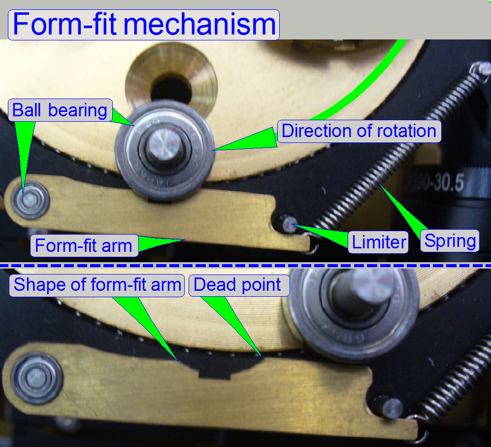 The disc is always
driven in direction from the spring to the mounting of the form-fit arm; the reason
for this is the shape of the form-fit arm.
The disc is always
driven in direction from the spring to the mounting of the form-fit arm; the reason
for this is the shape of the form-fit arm.
The use of ball bearings on
essential, important mountings guarantees the proper position of the objective
in the image path.
If the ball bearing of the
fitting pin arrives to the form-fit arm, and the dead point of the form-fit
mechanism is even crossed, the transport wheel stops the movement and the ball
bearing of the fitting pin will be locked in the shape of the form-fit arm by
the force of the spring.
The transport hole of the
transport wheel moves the objective disc with the help of the objective fitting
pin until the appropriate magnet
arrives over its sensor. This position is so defined, that the dead point
of the form-fit mechanism is even crossed.
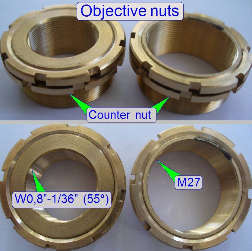 The objective nuts
holding the objectives, fixing the adjusted objective position and existing in
2 versions:
The objective nuts
holding the objectives, fixing the adjusted objective position and existing in
2 versions:
- The first version is used for objectives with
a thread of M27; this is the actual version, used for the 20x, 40x
objectives and the dummy objective as well; and
- The second version with Whitworth thread is
used for earlier types of Plan-Apochromat 20x objectives. Because the
production of Plan-Apochromat 20x objectives with Whitworth
W0.8"-1/36" thread was discontinued, today only objectives with
a thread of M27 are used.
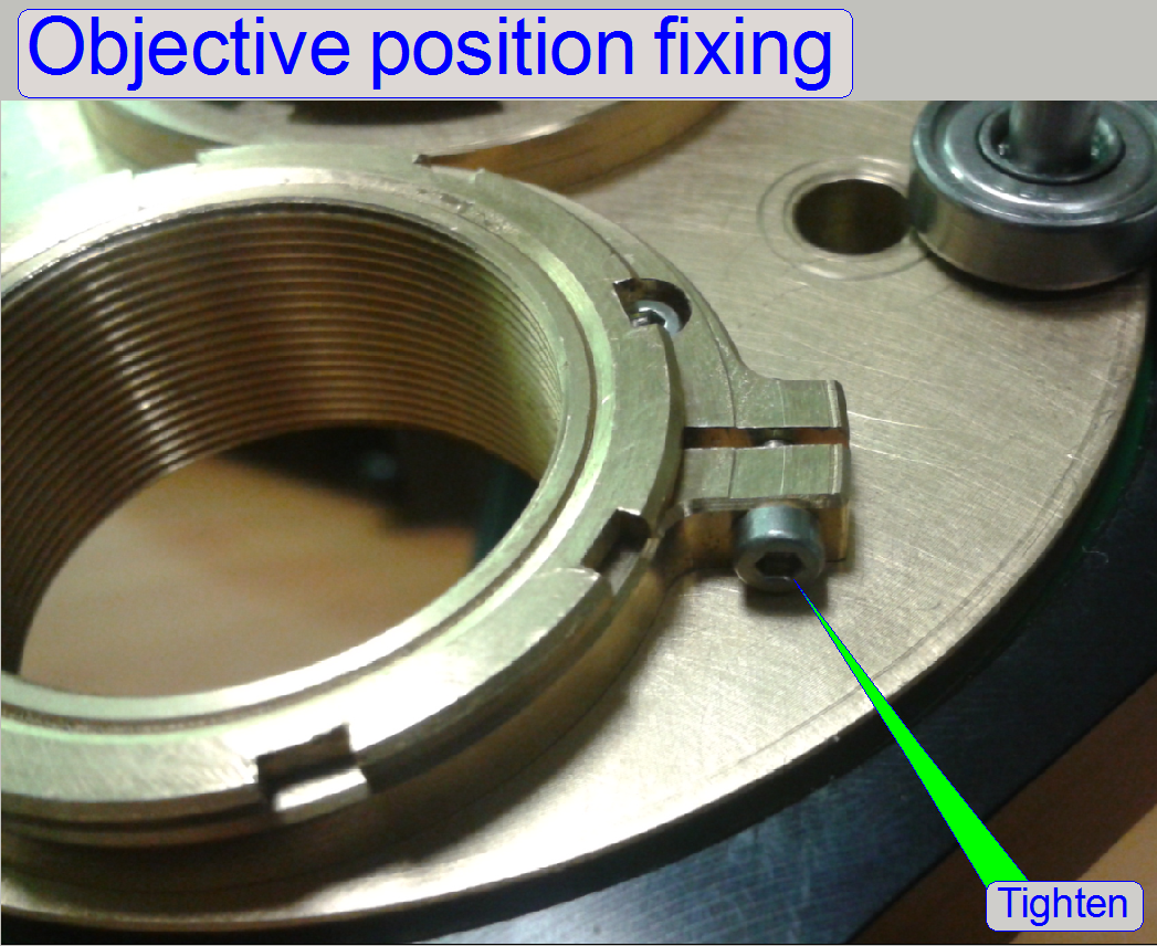
In newer versions (since
2014) the counter nut of the objective nut is replaced by a fixing clamp.
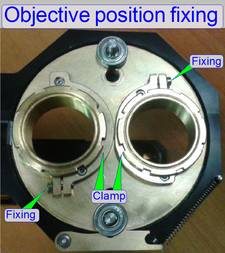
Now only 1 wrench is used to
adjust the objective position!
·
By using fixing clamps, the correct objective position
can be found easily.
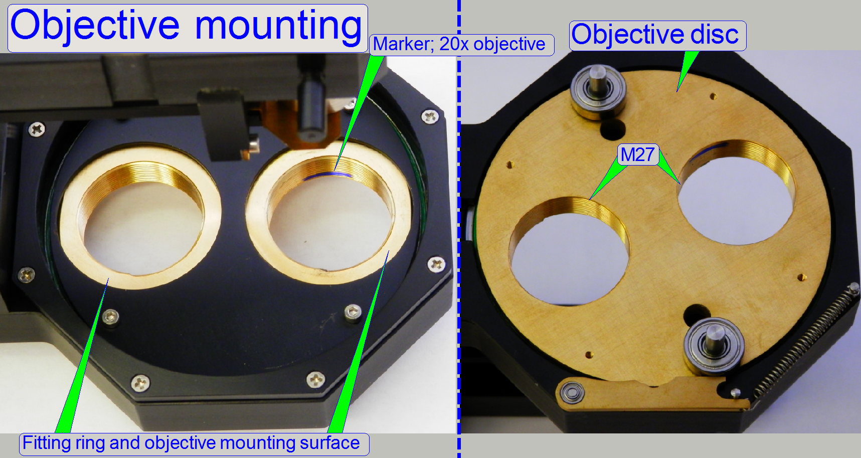
In this version, the objective
nuts are fully removed; the objective disc contains 2 drillings with M27
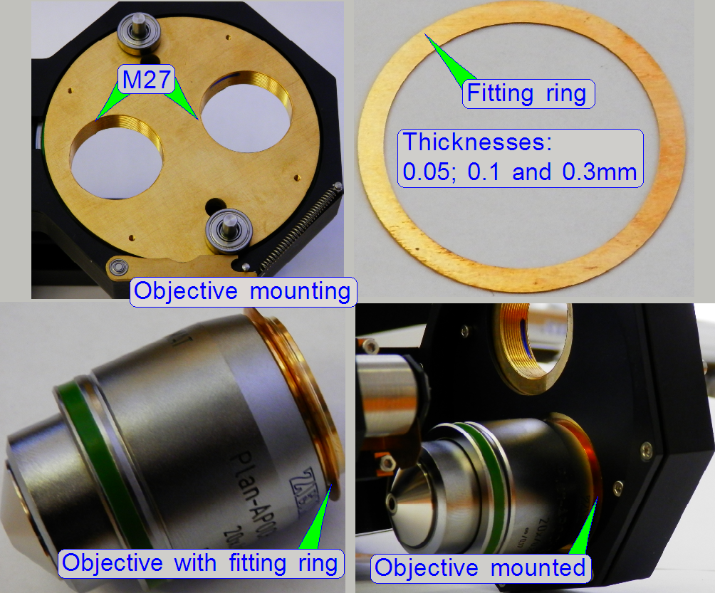
thread, so the objective can be mounted directly.
The distance of the objective
to the focus pin (the objective position) is adjusted by using fitting rings
between the objective mounting surface and the objective disc surface.
The nominal distance is
0.3mm.
By using and combining
fitting rings of different thicknesses, the objective position can be adjusted
individual (not recommended!).
If the objective was removed,
please insert the 20x objective into the mounting with the marker again, the
objective position was adjusted with this condition.
Set of objective fitting
rings
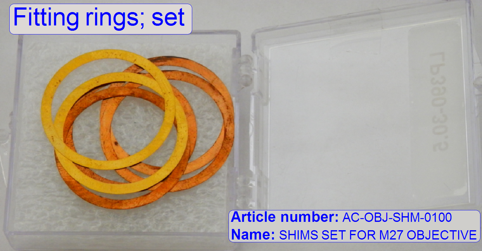 Name: SHIMS
SET FOR M27 OBJECTIVE
Name: SHIMS
SET FOR M27 OBJECTIVE
Article number: AC-OBJ-SHM-0100
Content: Nominal objective position is reached
if the thickness of the fitting ring is 0.3mm!
2x 0.3mm; already implemented
4x 0.1mm
2x 0.05mm
By using and combining
appropriate fitting ring thicknesses the distance of the objective to the
tissue can be adjusted in steps of 0.05mm.
·
Please use always the same distance of the objective
to the tissue on both objectives!
·
Because the Objective distance is already adjusted
(with the fitting rings of 0.3mm), the implemented fitting rings are not found
in the set, delivered with the scanner!
Mount the
objectives
Important
 Principally, the
objective position is already adjusted during the system integration process
and modification of the objective position should be done only in exceptions; modification is strongly not
recommended!
Principally, the
objective position is already adjusted during the system integration process
and modification of the objective position should be done only in exceptions; modification is strongly not
recommended!
·
If the objective(s) are dismounted, please leave the
fitting ring(s) on the objective (to avoid a mismatch)!
·
Always drive the 20x objective into the marketed
position, see above!
·
Always drive in the objective until it stops!
The focus position of both
objectives is found in the nominal focus position for the appropriate slide
thickness within a tolerance of ±50 focus steps!
If the option 40x
magnification is not used, the dummy objective is implemented in the objective
position 2.
 This way, a weight
displacement of the objective disc will be avoid.
This way, a weight
displacement of the objective disc will be avoid.
- If a weight displacement of the objective
disc would occur, the form-fit mechanism would not work correctly and the
objective may be misaligned in the optical axis.
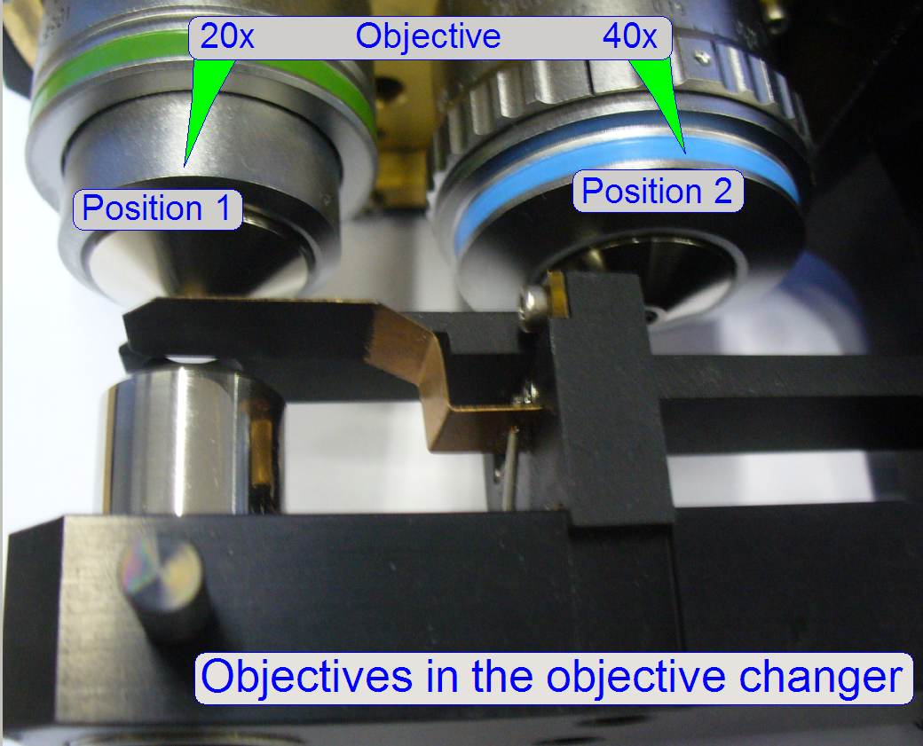
Mount the 20x objective
always into the position 1 and the 40x or dummy objective into the position 2.
- Because in all systems P250 always a 20x
objective is used (the 40x objective is optional) the start-up procedure
of the software calibrates the system with the 20x objective.
- Furthermore, all the optical and preview
adjustments are based on the 20x objective.
- The objective positions 1 and 2 are
decided, if the drive unit will be mounted; see also “Check / Set the
working position
Remark
Since the software version 1.16 the BF scan session may be executed with
the 20x or the 40x objective likewise.
![]() “Upgrade to the
software version 1.16” and “What is new” “Brightfield
scan with the 40x objective”
“Upgrade to the
software version 1.16” and “What is new” “Brightfield
scan with the 40x objective”
 The software setup of
the objectives is done in the dialog “Microscope settings”, there will be
defined if the 40x objective is present or not.
The software setup of
the objectives is done in the dialog “Microscope settings”, there will be
defined if the 40x objective is present or not.
![]() “Pannoramic_250_1.15_User's_Guide_EN_Rev1_FINAL.pdf”
“Pannoramic_250_1.15_User's_Guide_EN_Rev1_FINAL.pdf”
Remark
In the dialog
“Microscope settings”, any objective (20x or 40x) can be set to any position
(objective position 1 or 2), but we recommend the use of the objective 20x in
the position 1 and the 40x or dummy objective in the position 2, because some adjustments
(e.g. the preview
calibration procedure) requires the existence of the 20x objective in the
position 1.
 The objective
position can be modified according to the requirements of the used objective.
The objective
position can be modified according to the requirements of the used objective.
- To tighten or
loosening the objective nut, hold still the objective mounting nut with
one wrench and loosen or tighten respectively the lock nut with the other
wrench.
- By rotating the objective nut the objective
position will be modified and adjusted.
- Measure the thickness
of the slide (without cover slip) to be used to adjust the objective
position and calculate
the nominal focus pin position, this should be used as focus step
number in the live view of the scan program.
- Insert the measured slide, create the live
view, find the tissue and set the calculated number of focus steps.
- Rotate the objective nut toward or away
from the tissue, until the tissue becomes in focus.
- Tighten the lock nut; in newer solutions,
tighten the objective position fixing clamp.
- Find the real focus position by executing
the option “Auto focus”.
- Correct the objective position as necessary
by repeating previously explained steps.
After finishing the objective
position adjustment check the tightness of each objective!!
![]() “Adjust the
objective position”
“Adjust the
objective position”
“Setup and define
the implemented objectives”
Adjustments of the objective changer
unit
The mechanics of the
objective changer unit does not need adjustments; the positions of the Hall
sensors are fixed as well as the positions of the permanent magnets.
The adjustment is limited to
the following parts:
- Check / set the
working position 1 of the objective changer unit.
- Remove
/ mount
the objective changer drive unit.
- Remove / mount the
objective (and so adjust
the focus position also)
- Adjust the
condenser position
1.
With the service program set the Y-stage to Home1,2.
2.
Set the X-stage to Home1,2.
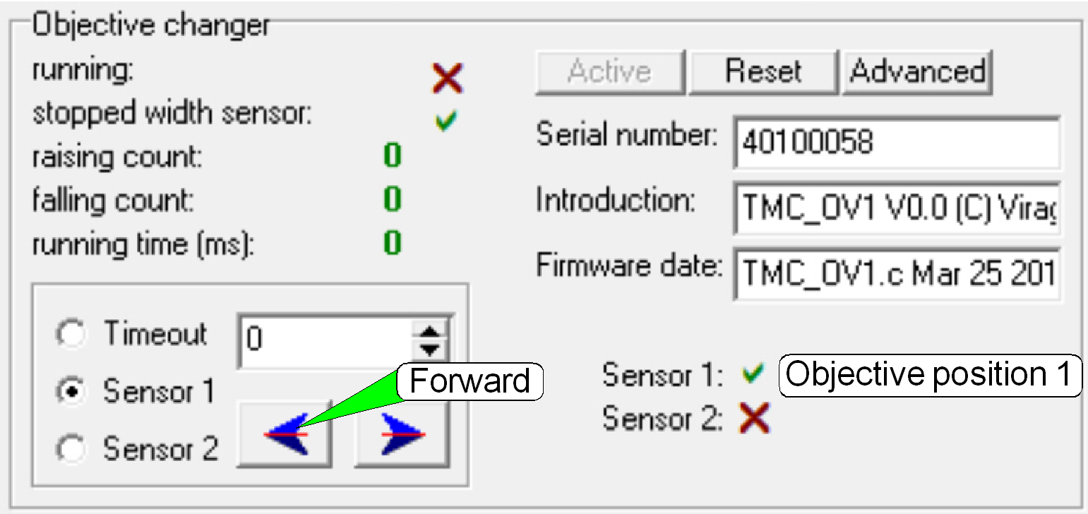
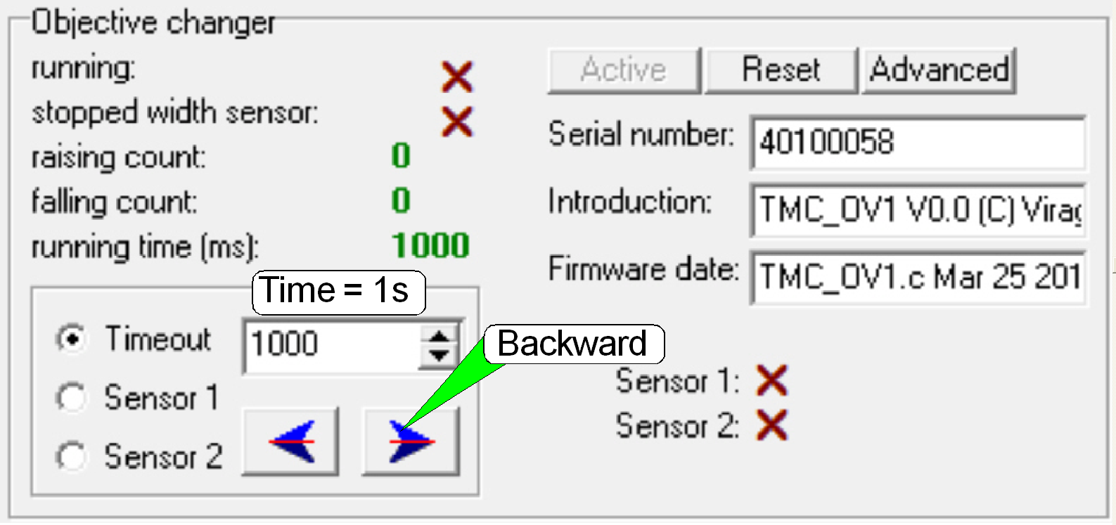
3.
In the tab “Objective changer”, select the sensor 1 and
press the button “Forward”; the 20x objective should move into the working
position of the objective changer unit, in the specified movement direction and
the form-fit mechanics should snap in correctly.
Set the working position 1
1.
If the working position 1 is not correct after the
check, remove the entire focus unit with objective changer.
2.
Remove the objective changer drive unit (probably the
stepper motor cables must not be disconnected).
3.
Rotate the objective disc by a ½ revolution so,
that the 20x objective stays in the working position.
4.
Mount the objective changer drive unit.
5.
Mount the entire focus unit with objective changer.
Remove the objective changer drive unit
1.
 Remove the focus
unit.
Remove the focus
unit.
2.
Remove the mounting bolts of the objective changer
drive unit.
3.
Easily separate the drive unit from the objective
changer mechanics.
Mount the objective changer drive unit
- With the
mounting of the drive unit the position of the 20x objective will be
defined also.
1.
Connect the cable DOJ-1 to the bus connector.
2.
In the tab “Objective changer”, of the service program
select the sensor 1 and press the button “Forward”; see above.
3.
Rotate the objective disc manually so, that the 20x
objective is in the working position of the objective changer unit.
4.
Fit the objective changer drive unit onto the
objective changer mechanics and drive in the mounting bolts.
5.
Mount the entire
focus unit with objective changer.
6.
Check the correctness
of the objective changer and its mechanics manually and with the service
program also.
7.
If the form fit mechanism does not snap in during the
normal exchange operation, modify a little bit the drive unit mounting position
until the dead point of the form fit mechanism is crossed correctly.
Dismount
or mount the objective
 The following procedure assumes that the focus unit with objective
changer is mounted and should not be dismounted.
The following procedure assumes that the focus unit with objective
changer is mounted and should not be dismounted.- If the focus unit
with objective changer is already removed from the scanner plate, you can remove the drive unit and so dismount or
mount the objectives.
1.
With the
program SlideScannerService.exe Set the X-Y-stage to the positions Y-Home1,2
and X-Home1,2.
2.
In the tab “Objective changer” move the objective
(position), to be dismounted or mounted into the working position.
3.
Select the option “Time out”, set a numerical value of
1300 ms and press the button Backward.
4.
Dismount or mount the objective. Hold the mounting nut
with the delivered wrench and loosen or tighten the objective by hand. Before
mounting a brand new objective, use a little bit grease on the mounting thread.
5.
If the objective nut position was previously not
adjusted, check the distance of the objective to the focus pin. If the focus
pin seems to touch the objective, correct the distance by rotating the
objective nut; the focus pin should never touch the objective!
6.
Adjust the distance of the objective to the plane of
the focus pin until a gap of approx.
7.
Select the appropriate sensor and press the button
forward; the actual dismounted position or the mounted objective should move
into the working position.
8.
Repeat the steps 2 to 7 with the other objective
(position), if required.
9.
If the 40x objective was mounted, check and set the
thickness of the cover slip; see also “The 40x objective”.
Check and adjust
the objective position
- This adjustment assumes
that the ex-center position of the focus unit is adjusted well and so, the
sine wave crosses the X-axis at +500 steps and the appropriate objective
is mounted.
To adjust the focus position
you can use a slide with a thickness in the range from 0.95 to
10.
Start the program SlideScanner.exe with the service
password.
11.
Clean the cover
slip and the slide bottom, then insert the measured slide with the known
thickness.
12.
Check the correct holding of the slide in the specimen
holder!
13.
Select a FOV of the tissue inside the preview window
with the positioning tool.
14.
Select the focus tab and live view.
15.
Press auto focus.
16.
 If the found focus
position is equal with the calculated focus position for that slide (a
deviation of + - 25 steps is possible) the objective position does not need
adjustments; the check is finished.
If the found focus
position is equal with the calculated focus position for that slide (a
deviation of + - 25 steps is possible) the objective position does not need
adjustments; the check is finished.
17.
If an adjustment of the objective position is
required, set the calculated number of focus steps in the live view, loosen the
lock nut of the objective mounting and drive the objective mounting nut so,
that the tissue becomes into focus (toward the cover slip or away from it
respectively).
18.
If the tissue becomes into focus, tighten the lock
nut; press the button “Auto focus” and repeat from step 15.
19.
Check the result again by pressing the button “Auto
focus” some times.
20.
If there are more then 25 steps difference to the
nominal (calculated) focus position, repeat the adjustment from step 15.
21.
Check the focus position on different positions of the
tissue.
22.
Change to the other objective position (tab “Service”,
“Microscope control” select the other objective position and go back to the tab
“Focus”, adjust the exposure time) and check or adjust the focus position for
the other objective by repeating the previous adjustment from step 13.
23.
If the 40x objective was adjusted, check / select the
thickness of the cover slip; see also “The 40x objective”
24.
After finishing the objective position adjustment
check the tightness of each objective!!
25.
If the adjustment is done, please move the objective
changer to the opposite objective position and again into the actual position (since
the software version 1.16 it is possible in the scan program) and start the
option “Auto focus” again. Only this way you can be sure that the actual
objective is right aligned in the optical axis.
Remark
Because we handled the
objective manually with the wrenches, it is easily possible to misaligning the
optical axis!
In earlier versions of the
file “SlideScanner.exe” you should start the scan program with the service
password and then, in the tab “Service” and “Microscope control” you can
exchange the objective by software also. Then check the focus position again
with the function “Auto focus”.
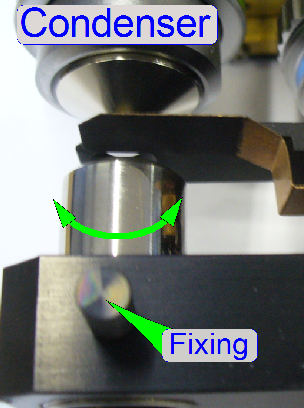
- Remove the
focus unit (optional).
- To remove the condenser, loosen its fixing
and drive the condenser out; away from the objective.
·
To mount the condenser, put it into its holder and
drive the condenser in; toward the objective.
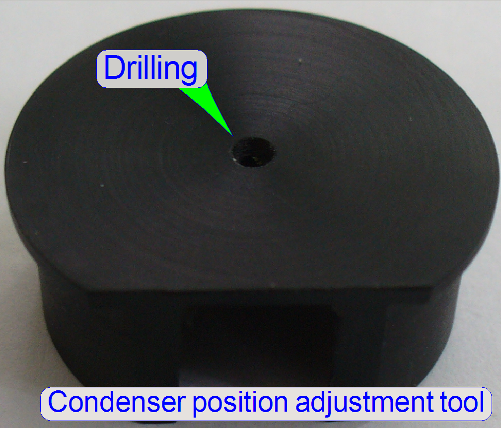 Condenser position adjustment tool
·
The condenser position adjustment tool is used to find
the optimal condenser position.
·
The adjustment tool is put onto the collimator lens
housing during the condenser position adjustment and if the center drilling of
the adjustment tool is in focus, the condenser position is nearly found.
The adjustment of the
condenser is important for the bright, uniform and optimal illumination of the FOV.
This reduces so the exposure time of the camera and increases the quality of
the scanned tissue.
The position of the condenser affects
the following:
- The size of the visible FOV (color shading)
- The image contrast
- The image resolution (the numerical aperture) and
- The exposure time.
- We assume that the focus unit and the
objective changer are already adjusted; the position of the objective is
correct.
- Use the program SlideScanner.exe and insert
a slide with cover slip, create a live view and click inside the tissue.
- Use the tool “Auto focus”.
- If the tissue is in focus, find a “clean”
FOV (without tissue or dust). Use the positioning tool
 and click outside the tissue but inside
the cover slip of the preview window in the program “SlideScanner.exe”.
and click outside the tissue but inside
the cover slip of the preview window in the program “SlideScanner.exe”.
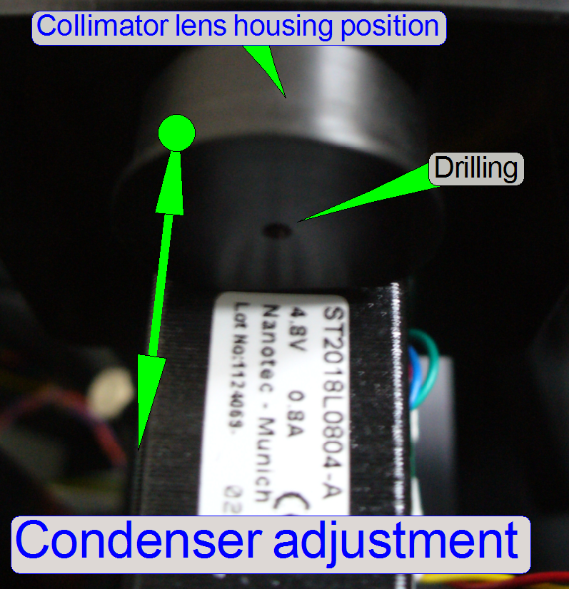
- Loosen the condenser’s fixing bolt and put
the condenser position adjustment tool over the collimator lens holder.
· If you can not see
the hole of the condenser position adjustment tool, calculate the exposure time
and move the adjustment tool on the optical axis until the image of the
drilling or a part of it can be seen in the live view.
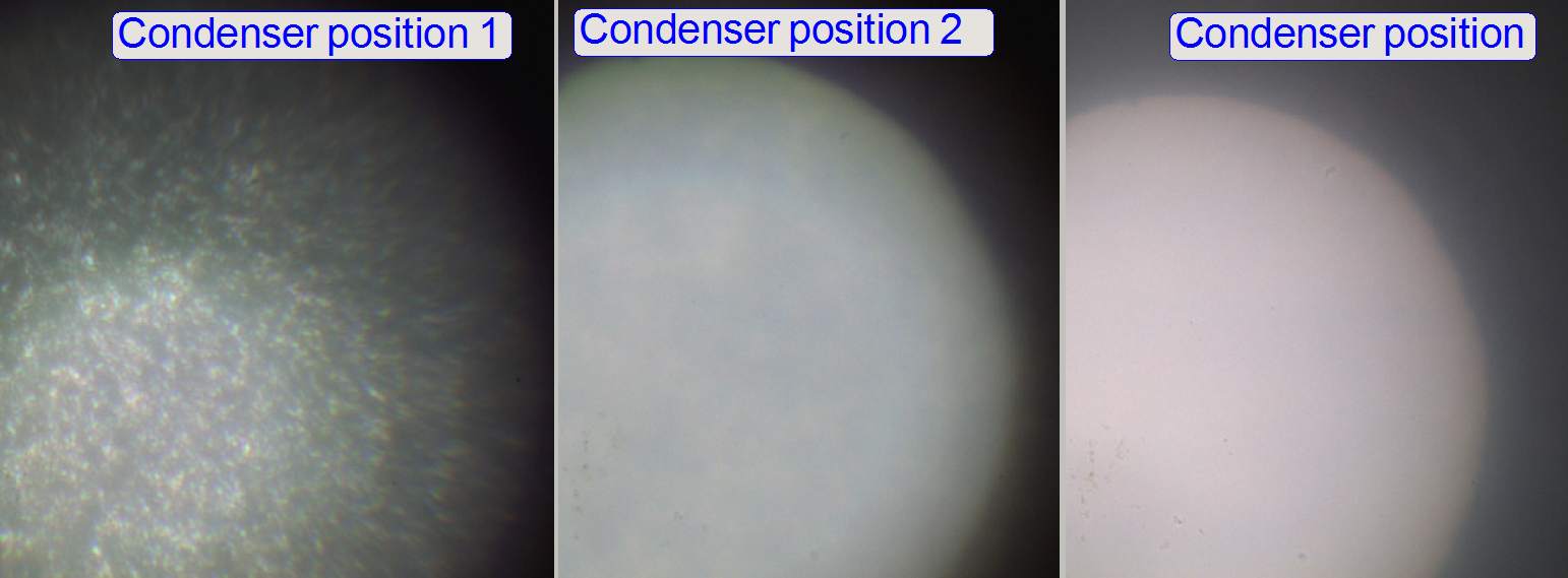
- Rotate the
condenser toward to the objective, so the start position for the
adjustment will be found; the brightness will increase.
- Rotate the condenser backward and
look at the live view. Beware of the condenser cover (shutter), don’t
close it and don’t bend it. You will see, that the drilling of the
condenser position adjustment tool comes into focus. While rotating the
condenser you can also observe that the brightness decreases.
 If the center
drilling of the adjustment tool is in focus, the condenser position is
nearly found, a small correction of the condenser position have to be
done, because the focus position of the drilling is not the real position
of the collimator lens. Drive the condenser by about ¼ revolution
more backward and stop the move of the condenser; tighten its fixing bolt.
If the center
drilling of the adjustment tool is in focus, the condenser position is
nearly found, a small correction of the condenser position have to be
done, because the focus position of the drilling is not the real position
of the collimator lens. Drive the condenser by about ¼ revolution
more backward and stop the move of the condenser; tighten its fixing bolt.
- Check the correctness of the adjustment in
the live view and by scanning a tissue or a part of it.
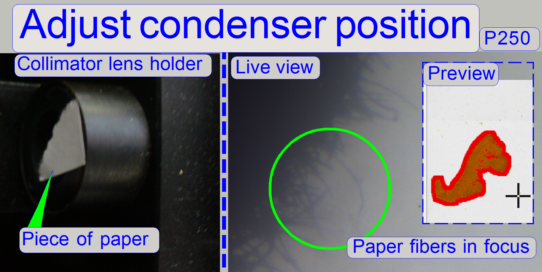
Alternatively, if the focus position of the tissue is correct, you may
stick a slice of paper onto the collimator lens holder.
·
Rotate the condenser, until the fibers of the paper
are in focus.

- The unevenly
illumination of the “clean FOV” will be corrected by software (the right
border is a little bit darker than the left side).
General
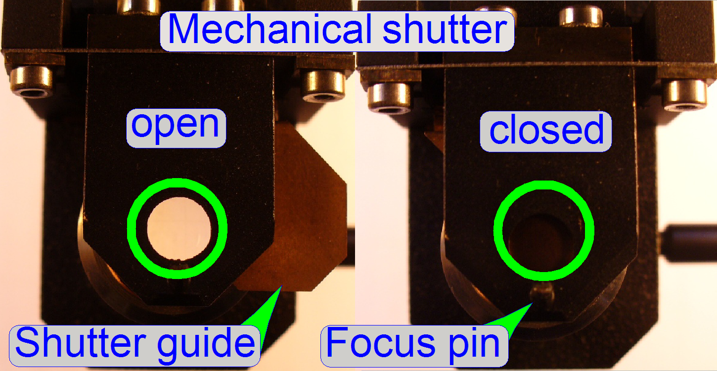
The mechanical shutter is implemented as a part of the focus unit and the
shutter guide is situated between condenser and 4:1 divider.
During fluorescent
scanning the shutter must be closed and insures so a dark background.
Other, unwanted fluorescent materials (e.g. painting, optics) can not reflect
the fluorescent light or can not fluoresce and so they will not disturb the
fluorescent view.
During bright field
illumination the shutter must be fully open to ensure a bright and evenly
illumination of the FOV.
Principle of shutter mechanics
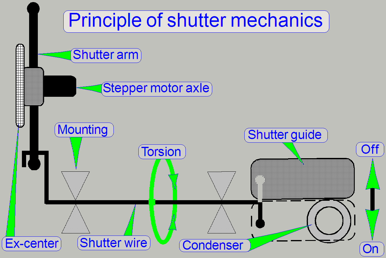
The shutter has only two
usable states, shutter on and shutter off. These positions are identical with
the hardware limits of the focus unit; in these positions the bright field
illumination should be fully opened or fully closed respectively. All other
possible positions of the shutter are not defined, therefore faulty positions
and not allowed during the scan process.
During rotation of the
stepper motor axle in direction to the negative limit of the focus unit, the
shutter wire will be touched by the shutter arm and is so moved to the shutter
off state (bright field illumination allowed). If the stepper motor axle is
rotated in direction to the positive limit, the other shutter arm will touch
the shutter wire and moves it so to the shutter on position (bright field
illumination disabled).
In practice it means, that
the shutter wire together with the shutter arms is the limiter of the focus
mechanics and with this limiter the shutter on / off option is realized.
- During focusing the shutter wire will never
be touched by the shutter arm.
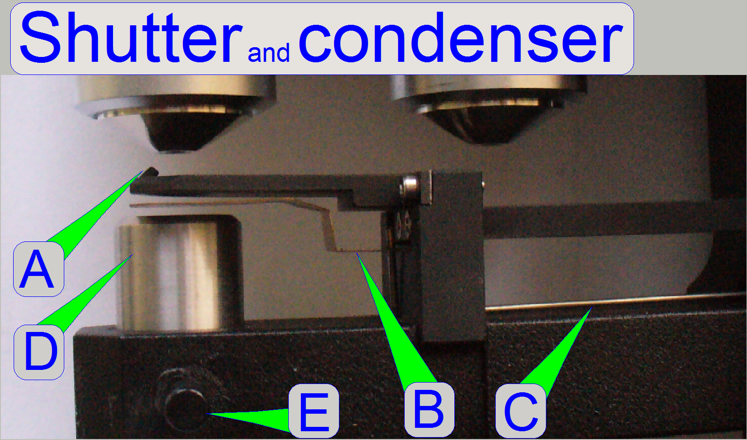
A = Focus
pin
B = Shutter
guide
C = Shutter
wire
D =
Condenser
E =
Condenser fixing
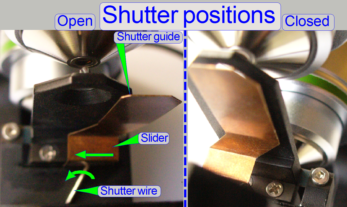
If the shutter wire is
touched by the shutter arm, the torsion is transmitted via the shutter wire to
the slider of the shutter guide. The slider brings so the shutter guide into
the proper position.
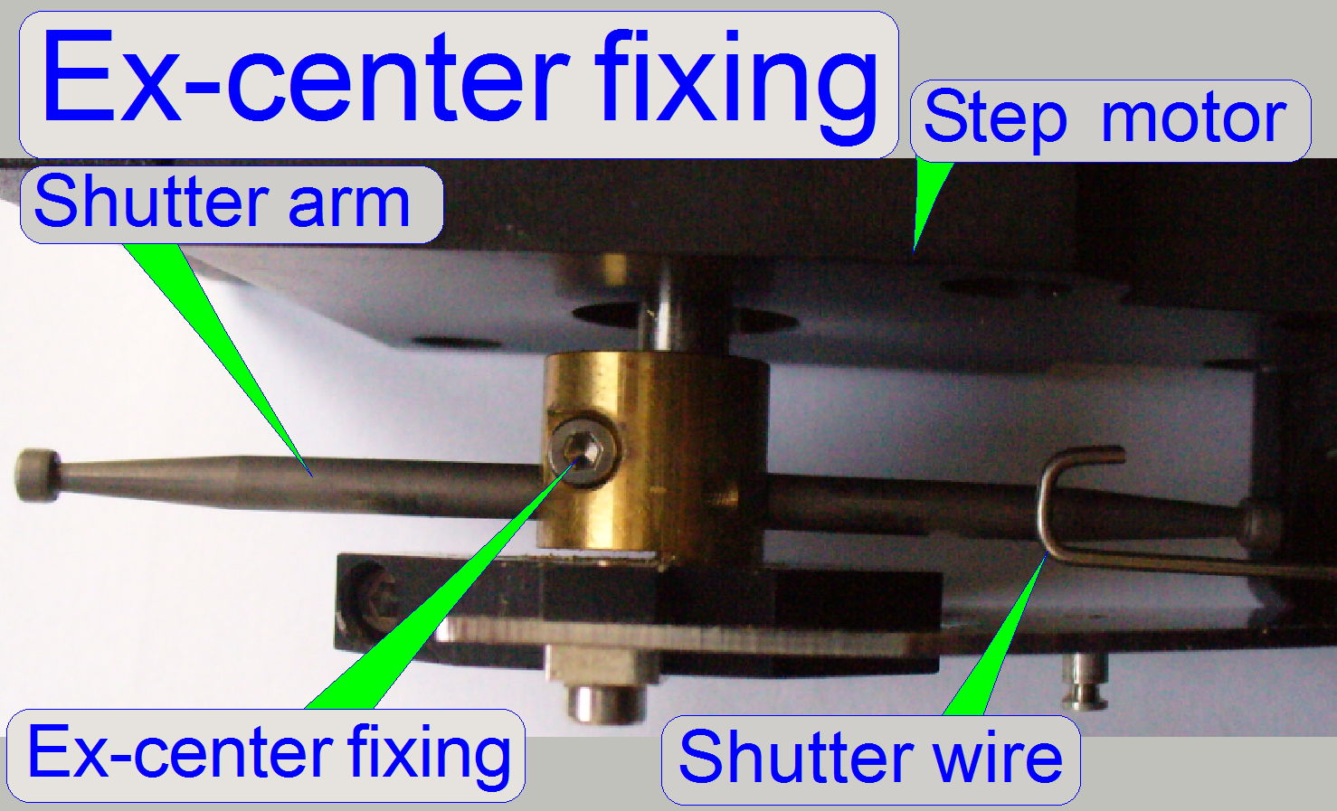
Adjustments of the
focus part and shutter mechanics
This adjustment must be done only
if the ex-center was dismounted or the fixing bolt was loosened. With this
adjustment the focus position is set to be +500steps nominal.
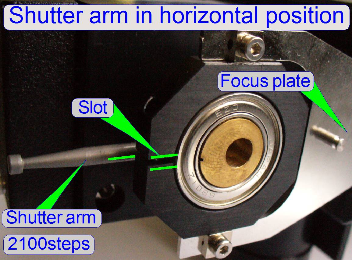
Because in this position the
fixing bolt can not be loosened or tightened, we use the focus stepper motor
position of 2100 steps for this adjustment.
1.
Loosen the ex-center fixing bolt so, that the
ex-center can be moved on the motor axle.
2.
With the service program set the focus unit to
Home1,2.
3.
Go forward to the focus motor position 2100 steps.
4.
Bring the ex-center into the horizontal position (the
shutter arms shows to the left and to the right; use the slot of the ex-center
mounting to find the proper position. Before you are tighten the ex-center
fixing bolt please check the position of the shutter arm in relation to the
shutter wire also. The shutter arm should touch the shutter wire nearly in the
middle of the hook. To reach this, bring the ex-center in proper position on
the motor axle and tighten the fixing bolt.
 Attention
A small gap between motor mounting surface and
ex-center mounting should exist, otherwise, if the ex-center mounting rubs on
the motor mounting surface, the focus unit may lost rotor movements and so the
scanned tissue may be out of focus or blurry, even if the focus rotor direction
had changed.
5.
Go to the positions Home1,2.
6.
Go forward to the focus motor position +500 steps.
7.
In this position the shutter arms should showing
exactly up and down. A deviation of approx. 10 steps from the vertical
direction is allowed. If the deviation is too much, repeat the adjustment from
step 1.
Find the hardware limits for the focus unit
This procedure must be done
only if the ex-center was dismounted or its fixing bolt was loosened. Before
the following procedure is done, the previous adjustment “Adjust the ex-center
position” should be correct.
· The
path of the file MicroscopeConfiguration.ini, in the software version with the
operating system Windows® 7 is:
C:\ProgramData\3DHISTECH\SlideScanner\MicroscopeConfiguration.ini
![]() “How
to define the hardware limits”
“How
to define the hardware limits”
Find the negative limit
8.
With the
service program set the focus unit to Home1,2.
9.
Go forward to the focus motor position -1750 steps.
10.
 Go backward +1750
steps.
Go backward +1750
steps.
11.
Press Home1 (only). There should be not more then +-2
steps difference to Home1.
If there are more
steps lost, decrease the actual number of steps by 10 and repeat from step
12.
If there are not more then 2 steps difference to
Home1, increase the number of steps by 10 and repeat from step
13.
The negative limit is found correctly if the motor
movement has no steps lost and the actual number of steps, increased by 10
would produce lost steps.
 The found negative limit can
differ by more ten steps from unit to unit. The reasons are the tolerances of
the components and the used position of the ex-center in relation to the motor
axle.
The found negative limit can
differ by more ten steps from unit to unit. The reasons are the tolerances of
the components and the used position of the ex-center in relation to the motor
axle.
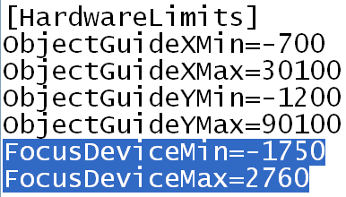
14.
Update the
parameter value of the parameter “FocusDeviceMin” with the found number of the
actual steps in the file “MicroscopeConfiguration.ini” section
[HardwareLimits].
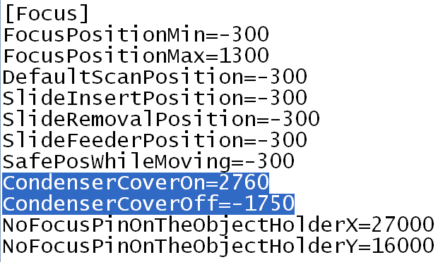
15.
Update the parameter value of
the parameter “CondenserCoverOff” with the found value in the file
“MicroscopeConfiguration.ini” section [Focus].
Find the positive limit
16.
 With the service
program set the focus unit to Home1,2.
With the service
program set the focus unit to Home1,2.
17.
Go forward to the focus motor position +2750 steps.
18.
Go backward 2750 steps.
19.
Press Home1 (only). There should be not more then +-2 steps
difference to Home1.
If there are more
steps lost, decrease the actual number of steps by 10 and repeat from step
20.
If there are not more then 2
steps difference to Home1, increase the number of steps by 10 and repeat from
step
21.
The positive
limit is found correctly if the motor movement has no steps lost and the actual
number of steps, increased by 10 would produce lost steps.
The found positive
limit can differ by more ten steps from unit to unit. The reasons are the
tolerances of the components and the used position of the ex-center in relation
to the motor axle.
22.
Update the parameter value of the parameter
“FocusDeviceMax” with the found value in the file “MicroscopeConfiguration.ini”
section [HardwareLimits].
23.
Update the parameter value of the parameter “CondenserCoverOn”
with the found value in the file “MicroscopeConfiguration.ini” section [Focus].
Dismount; mount the focus unit
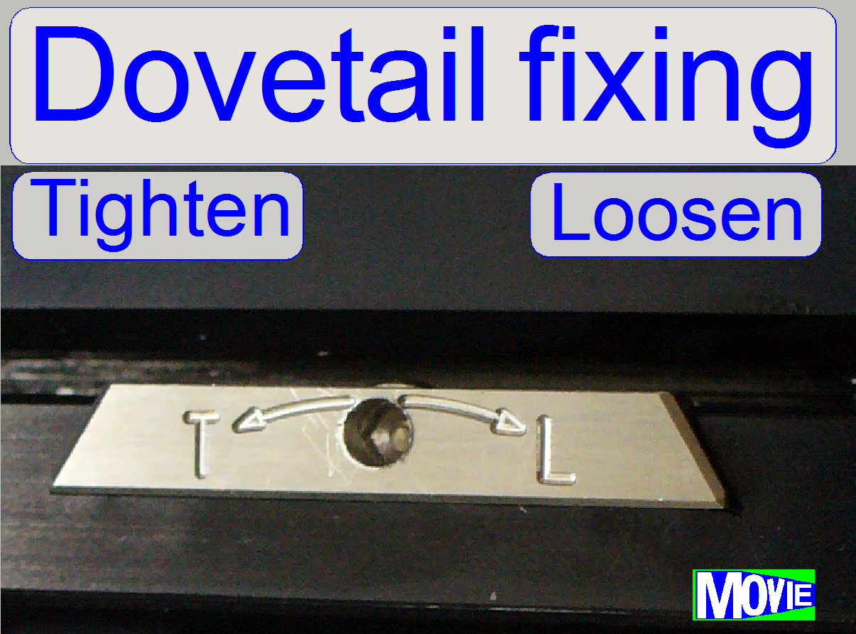
The mounting of the focus
unit with objective changer and the mounting of the X-Y-stage is realized with
dovetails; these are hold by dovetail fixing clamps.
- Rotate the screw driver clockwise to open
(loosen) the dovetail clamp.
 Make sure, that
the X-Y-Stage is not in the X-home position, because in this position the
focus unit can not be removed.
Make sure, that
the X-Y-Stage is not in the X-home position, because in this position the
focus unit can not be removed.
1.
With the service program go forward to the position
10,000 steps in +X direction (3 full turns of the motor axle).
2.
Disconnect the bus cables DOJ-1 of the objective
changer and FCJ-1 of the turret stepper motor.
3.
Disconnect the cables of the focus motor (optional).
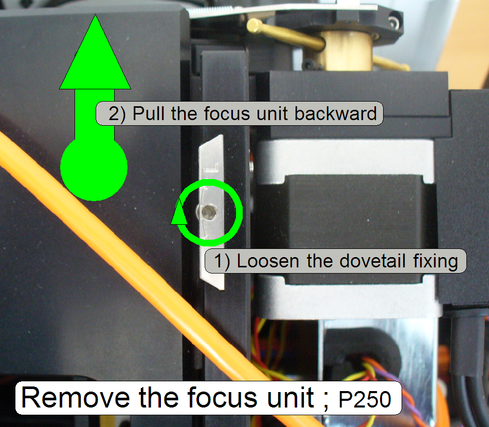
4.
Loosen the
fixing bolt of the focus unit mounting; turn the screw driver clockwise!
5.
Remove the entire focus and objective changer unit by
pulling the unit backward.
Watch Video: Remove focus unit (SCAN)
6.
Insert the focus unit with objective changer into the
dove tail of the scanner plate until the physical limit is reached; take care
on the objectives.
7.
Tighten the fixing bolt of the focus unit mounting; turn
the screw driver counter clockwise!
8.
Connect the bus cables DOJ-1 of the objective changer
and FCJ-1 of the turret stepper motor.
9.
Connect the cables of the focus motor.
Watch Video: Mount focus unit (SCAN)
Setup and define the
implemented objectives
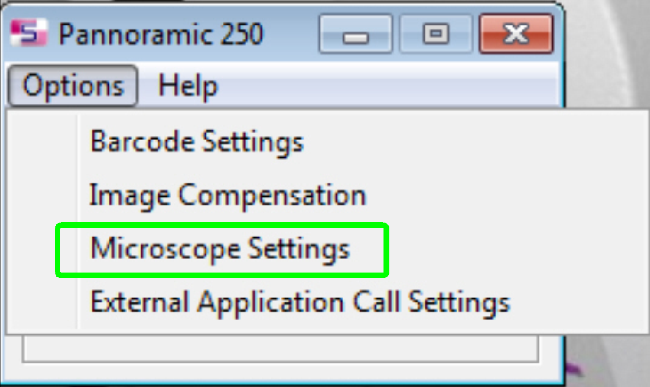 If the
objective(s) are implemented and the program “SlideScanner.exe” finished the
start up procedure, select the option “Microscope Settings” in the menu
“Options”.
If the
objective(s) are implemented and the program “SlideScanner.exe” finished the
start up procedure, select the option “Microscope Settings” in the menu
“Options”.
- The setup of the objective(s) is done
mostly together with the install of the present cameras.
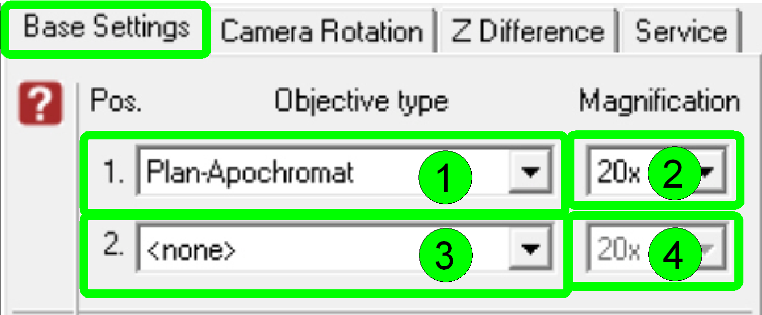 In the dialogue
“Base Settings” the implemented objectives are selected and parameterized.
In the dialogue
“Base Settings” the implemented objectives are selected and parameterized.
By default and in the scanner P250
- Select the type “Plan-Apochromat” (1) and
the magnification of 20x (2) in the objective position 1
- Select the type “Plan-Apochromat” (3) and
the magnification of 40x (4) in the objective position 2.
§
If there is only a 20x objective implemented into the
scanner, select “<none>” (3) in the objective position 2.
Remark
Of course, the dialogue
accepts any kind of magnification in any objective position, but in the
Pannoramic 250 the 20x objective should be always in the objective position 1
because this is the default objective and some adjustment procedures (e.g. the preview calibration
process) uses the 20x objective in the objective position 1!
Align the objective
into the optical axis
Attention
The alignment of the objective position to the optical
axis is already done and finished; this is not a usual adjustment.
The following calibration
should be done only, if the objective changer unit mounting was loosened,
altered or the objective changer unit was separated and reassembled to the
focus unit; so the optical axis will not be strait.
- The following procedure will be used to fit
the objective (position) into the optical axis correctly.
- In any cases, check the alignment
first, before starting the adjustment.
- Check the correct working of the form-fit mechanics
also.
Remark
The aligning procedure is
advised and described for the 20x objective and the objective position 1.
If the 20x objective position
is equipped with an objective nut using Whitworth thread, you can use
unhesitatingly the 40x objective position to align the objective changer unit!
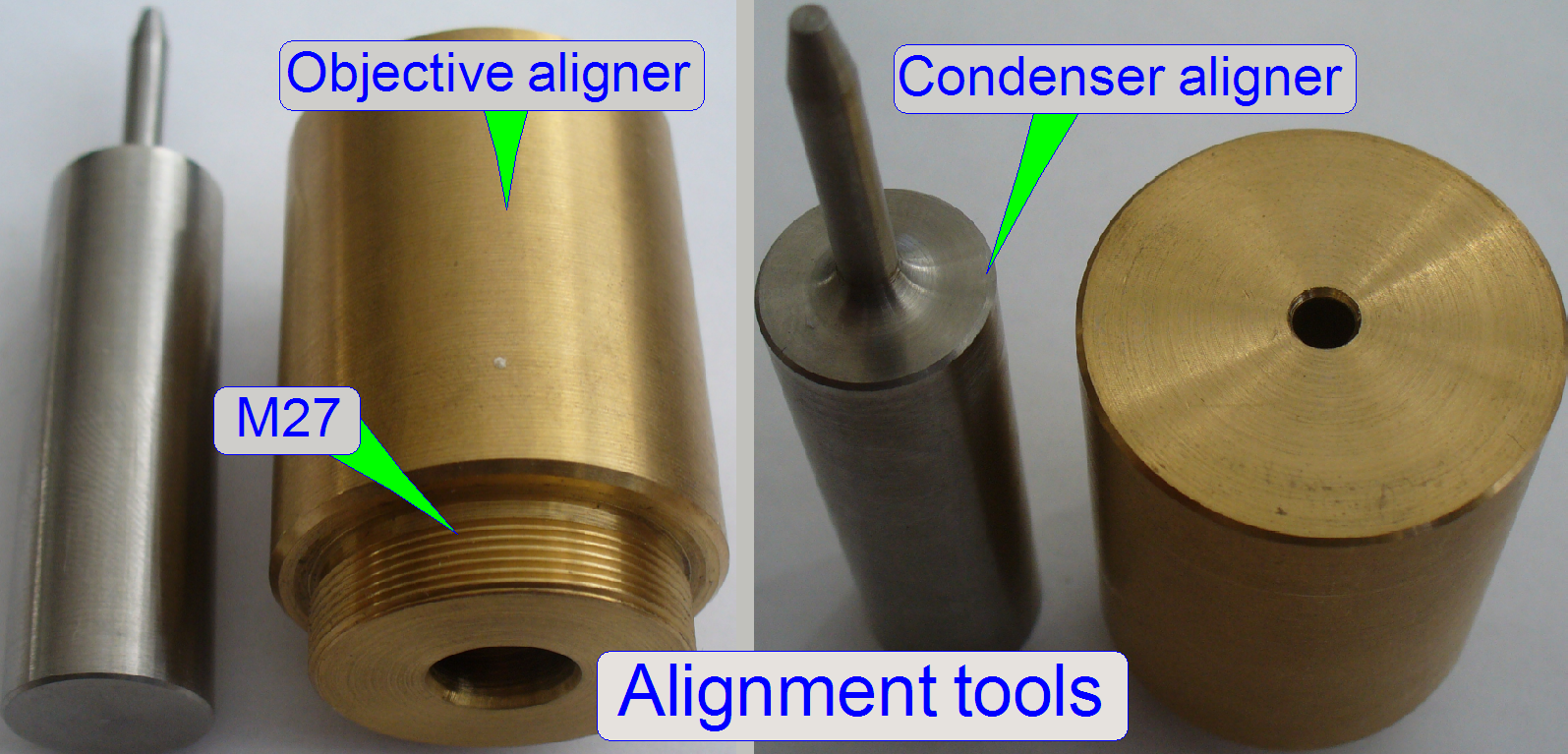
The alignment is done
mechanically; the objective pupil position (represented by the drilling of the
objective aligner) will be fit into the optical axis by the help of the condenser
aligner pin. During this fitting operation the objective changer unit mounting
is barely loosened (except you are checking the correctness of the alignment).
The unit mounting bolts will be tightened, if both adjustment tools fitting
easily and the form-fit mechanics fix the objective position correctly.
- In all cases, the lock nut of the objective
mounting nut as well as the objective aligner should be fully tightened
during the aligning procedure.
- The alignment tools can also be used to
check the objective position alignment if the objective changer unit
mounting is tightened!
1.
With the service program set the objective changer
into the default position by pressing the radio button “Sensor
2.
Disconnect the cables of the objective changer and the
stepper motor cables.
3.
Remove the entire focus
unit with the objective changer.
4.
Remove the
drive unit.
5.
Rotate the objective disc manually by about a ¼
revolution and remove the 20x objective; do not loosen the lock nut or the
objective mounting nut; otherwise the objective position has to be adjusted
again!
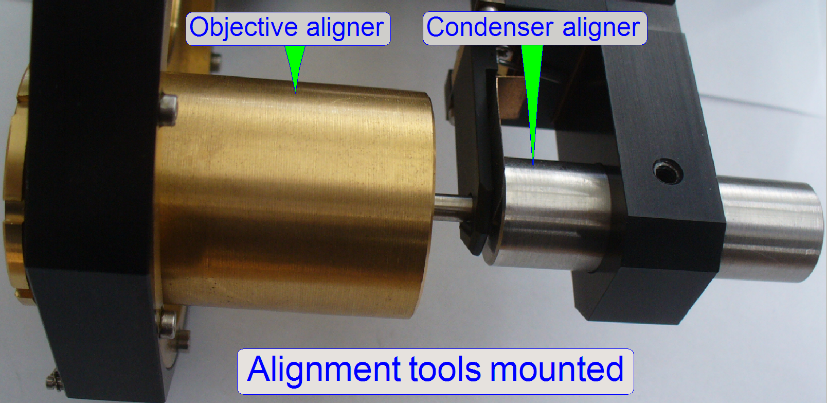
6.
Drive the objective aligner into
the objective mounting of the 20x objective until it stops.
7.
Mark the condenser position (e.g. with a pen), then remove the condenser.
8.
Make sure, the mechanical shutter is open.
9.
Insert the condenser aligner into the
condenser mounting.
10.
If the condenser aligner moves easily in / out in the
condenser mounting (if it would falling out by gravity) and the form-fit
mechanics fix the objective position correctly, the adjustment is correct.
11.
If the condenser aligner can not be inserted or moves
strong, the objective is misaligned; execute the aligning procedure.
12.
If the aligning result is acceptable, remove the
condenser aligner and mount
the condenser again (until the previously signaled position).
13.
Remove the
objective aligner and mount
the 20x objective again.
14.
Put the 20x objective into the working position
manually and mount
the drive unit.
15.
 Mount the entire
focus unit with objective changer and connect the cables.
Mount the entire
focus unit with objective changer and connect the cables.
16.
With the service program check the functionality of
the focus unit and the objective changer unit as well, the 20x objective have
to be in the working position if ‘Sensor
17.
Check or
adjust the objective position.
18.
Check the
focus position
19.
Check or adjust
the condenser position.

1.
With the service program set the objective changer
into the default position by pressing the radio button “Sensor
2.
Disconnect the cables of the objective changer and the
stepper motor cables.
3.
Remove the entire
focus unit with the objective changer.
4.
Dismount
the drive unit.
5.
Rotate the objective disc manually by about a ¼
revolution and remove the 20x objective; do not loosen the lock nut or the
objective mounting nut; otherwise the objective position has to be adjusted
again!
6.
Drive the objective aligner into
the objective mounting of the 20x objective until it stops.
7.
Mark the condenser position (e.g. with a pen), then remove the condenser.
8.
Loosen the unit mounting bolts of the entire objective
changer unit so, that the unit becomes barely moveable.
9.
Make sure, the mechanical shutter is open.
10.
Insert the condenser aligner into the
condenser mounting and adjust the entire objective changer unit position in
relation to the focus unit.
11.
If the condenser aligner moves easily in / out in the
condenser mounting (if it would falling out by gravity) and the form-fit
mechanics fix the objective position correctly, the unit mounting bolts should
be tightened.
12.
Check the easily movement of the condenser aligner in
the condenser mounting again; hereby the form-fit mechanics should fix the
objective position correctly also.
13.
If the condenser aligner moves strong, repeat this
procedure from step 8.
14.
If the aligning result is acceptable, remove the
condenser aligner and mount
the condenser again (until the previously signaled position).
15.
Remove the objective aligner and mount the 20x objective
again.
16.
Put the 20x
objective into the working position manually and mount the drive unit.
17.
Mount the entire
focus unit with objective changer and connect the cables.
18.
With the service program check the functionality of
the focus unit and the objective changer unit as well, the 20x objective have
to be in the working position if the radio button “Sensor
19.
Check / adjust
the objective position.
20.
Check the
focus position
21.
Check / adjust
the condenser position.