RGB BF illumination unit
Following chapter
summarizes the information about principles and construction of brightfield illumination in scan paths of Pannoramic scanners.
The described
unit is momentarily used in Pannoramic Confocal, DESK_II, MIDI_II and SCAN_II type scanners.
In SMD_II-type scanners,
the software version 1.21 or higher is required and is implemented since summer
2016.
 The construction of the BF optical path
uses only a monochrome camera, so only monochrome images can be produced.
The construction of the BF optical path
uses only a monochrome camera, so only monochrome images can be produced.
- Monochrome cameras have an important
advantage in relation to color cameras, today,
the pixel size is the possible smallest.
To create color
information of the tissue with a monochrome camera, we illuminate the tissue
with monochrome light.
If the tissue is
illuminated by blue light, and we are making an image of the Field of view, the
gray scaled camera image contains the intensity of the blue parts in the
tissue.
Because the pixel
resolution of the camera is very high and the resolution of the image's gray
scale is 10bit per pixel or higher (depending on the used camera), very
detailed information of the blue part in the FOV, related to the appropriate
pixel can be reached.
If we repeating
the procedure with the colors Green and Red, 3 images of the same FOV are
produced (a Red, Green and Blue image) and so, the software knows detailed
color information about each pixel of the Field Of View.
By using the
software coloring method the true color information of each pixel is found.
By using cameras
with a large image sensor low shutter time and high pixel resolution (small
pixel size), the scan time of the tissue can be held in acceptable boundaries
and the result is an image with high resolution and high color fidelity.
Remark
 In SCAN_II the Illumination mirror is not
required; it is replaced by the illumination tube.
In SCAN_II the Illumination mirror is not
required; it is replaced by the illumination tube.
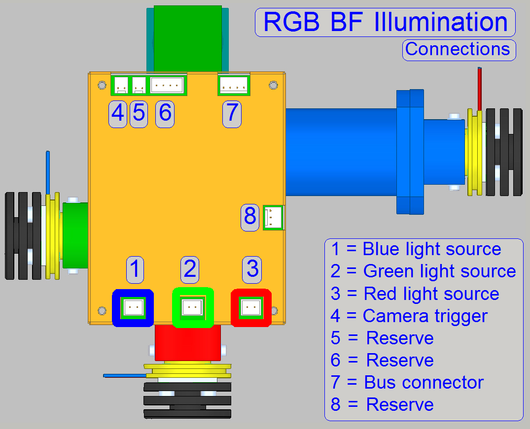
Illumination unit
consists of:
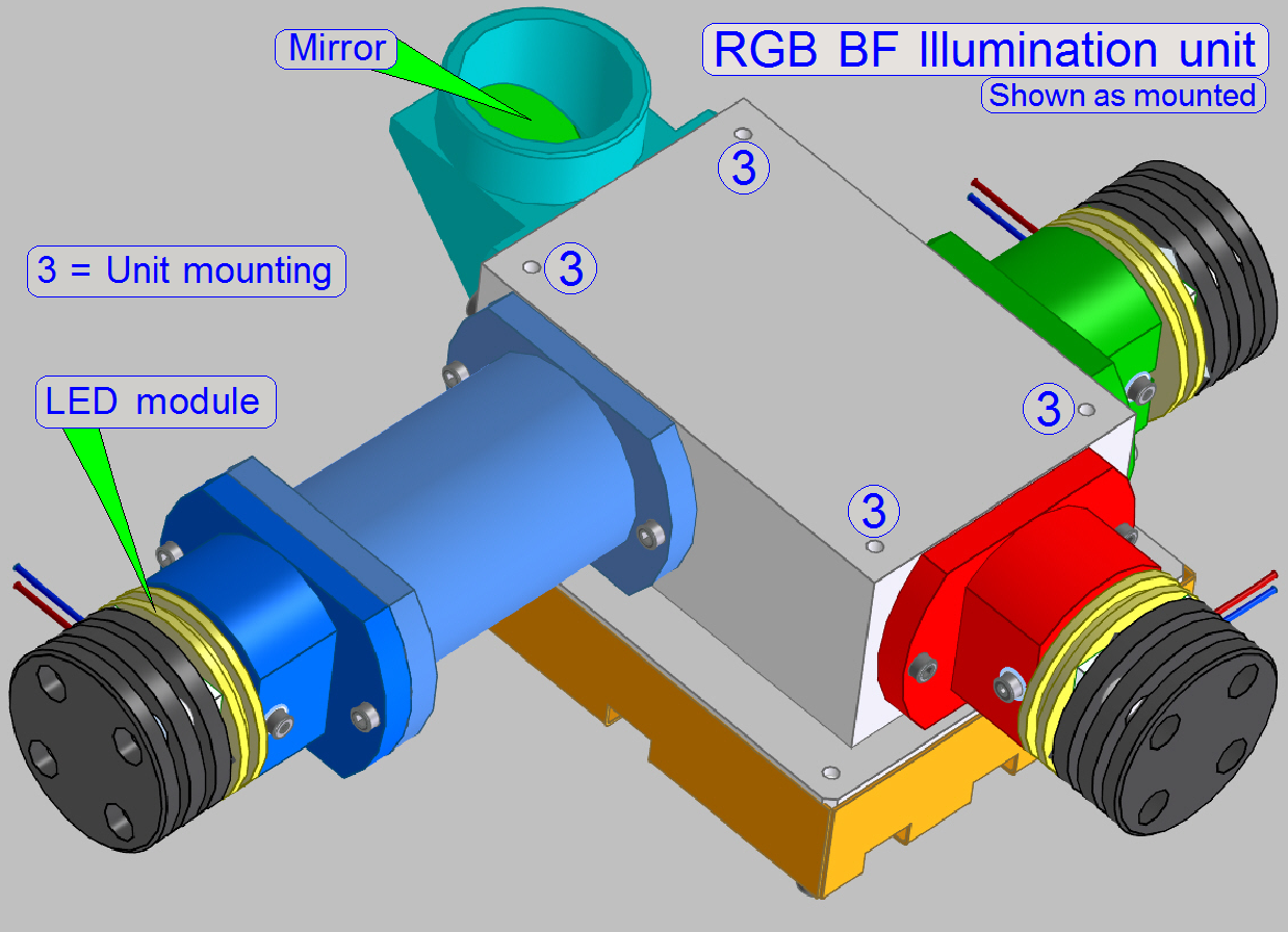
Watch video: RGB BF Illumination unit
Housing
with:
·
 two
dichroic
beamsplitters to route the light rays of Red,
Green and Blue to the BF illumination mirror
two
dichroic
beamsplitters to route the light rays of Red,
Green and Blue to the BF illumination mirror
· Dichroic beamsplitters
are mounted in an angle of 45º in relation to the light sources
· the mounting of illumination modules
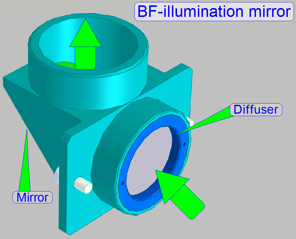
· Illumination mirror with
diffuser
· Mountings to the scanner plate of the PCON;
see image above
· Electronics (power supply and control of the
LEDs; not shown here)
·
The
illumination components are mounted to the Illumination unit housing by bolts!
·
Adjustments
are not required.
·
Maintenance
is not required.
Used beamsplitters
·
 The Dichroic beamsplitters are always mounted in an angle of 45º in
relation to the light sources and the optical axis
The Dichroic beamsplitters are always mounted in an angle of 45º in
relation to the light sources and the optical axis
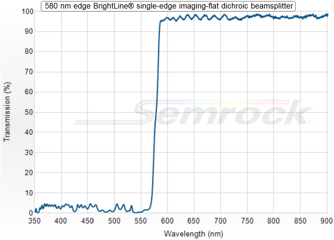
Dichroic beamsplitter 1; 580nm
·
All
light wavelengths above 580nm (the red and orange part of the visible light)
passing thru the dichroic beamsplitter;
all wavelengths below 580nm, the yellow, green, blue and violet light, will be
reflected.
In
other words:
·
The lower
wavelengths, below 580nm are always reflected while the higher wavelengths,
above 580nm pass through the beamsplitter!

Part Number: FF580-FDi01-25x36
Dichroic beamsplitter 2; 488nm
·
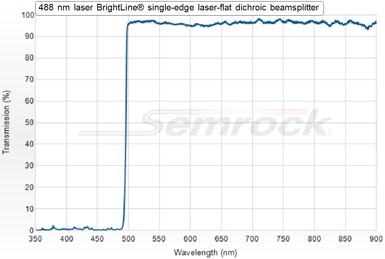 All light wavelengths above 488nm (the red, yellow
and green light) passing thru the dichroic beamsplitter all wavelengths below 488nm, the blue and violet
light, will be reflected.
All light wavelengths above 488nm (the red, yellow
and green light) passing thru the dichroic beamsplitter all wavelengths below 488nm, the blue and violet
light, will be reflected.
In other words:
·
The
lower wavelengths, below 488nm are always reflected while the higher
wavelengths, above 488nm pass through the beamsplitter!
Part Number: Di02-R488-25x36

 By using the dichroic
beamsplitters the required wavelengths for the colors
Red, Green and Blue can be filtered from the white light, emitted by the LED.
By using the dichroic
beamsplitters the required wavelengths for the colors
Red, Green and Blue can be filtered from the white light, emitted by the LED.
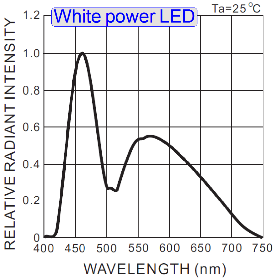
·
Also
important in this construction is the emitted wavelength spectrum of the white
power LED.
·
The
violet light, in the range from 390 ~ 420nm does practically not exist.
·
The
visible white light is defined in the range of approximately 400 ~ 700nm.
Significant
colors can be assumed in the following wavelength ranges
|
Color |
Range |
Typical |
|
[nm] |
[nm] |
|
|
Violet |
390 ~ 430 |
410 |
|
Indigo |
430 ~ 450 |
440 |
|
Blue |
450 ~ 495 |
460 |
|
Green |
500 ~ 560 |
535 |
|
Yellow |
560 ~ 590 |
575 |
|
|
590 ~ 620 |
610 |
|
Red |
620 ~ 700 |
660 |
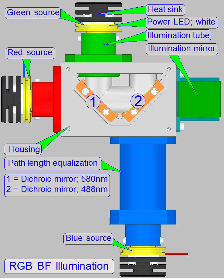
Illumination
path
The illumination
module creates always white light in the wavelength range of ~400 to 700nm.
·
The shown
color of the illumination tube is only used to show the arrangement of the
light sources in relation to the beamsplitters.
·
The
illumination modules are switched on separately, so only 1 wavelength range
will be created at a time.
·
Detailed
information about the working principle will be shown in the following.
Remark
In SCAN_II the Illumination mirror is not
required; it is replaced by the illumination tube.
The Red light source
emits light in the range of 400 ~ 700nm
·
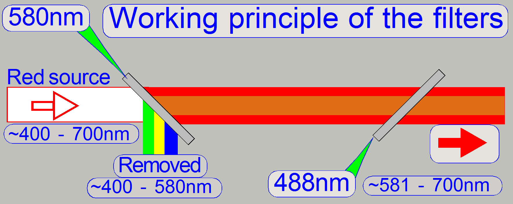 The unwanted wavelength range from 400 ~
580nm (yellow, green and blue) will be filtered out (reflected) by the dichroic beamsplitter with a
nominal wavelength edge of 580nm.
The unwanted wavelength range from 400 ~
580nm (yellow, green and blue) will be filtered out (reflected) by the dichroic beamsplitter with a
nominal wavelength edge of 580nm.
The Green light source
emits light in the range of 400 ~ 700nm
·
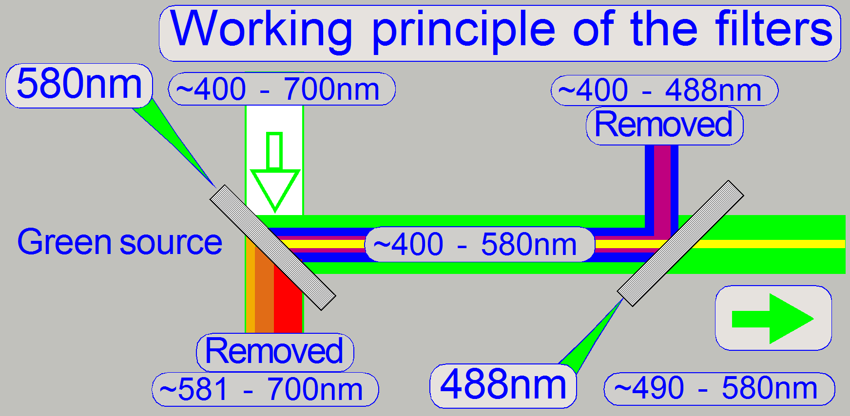 The unwanted wavelength range from 590 –
700nm (yellow, orange and red) will be filtered out (passes thru) by the dichroic beamsplitter with a
wavelength edge of 580nm.
The unwanted wavelength range from 590 –
700nm (yellow, orange and red) will be filtered out (passes thru) by the dichroic beamsplitter with a
wavelength edge of 580nm.
·
The
blue part will be filtered out (reflected) by the dichroic
beamsplitter with a wavelength edge of 488nm.
The Blue light source
emits light in the range of 400 ~ 700nm
·
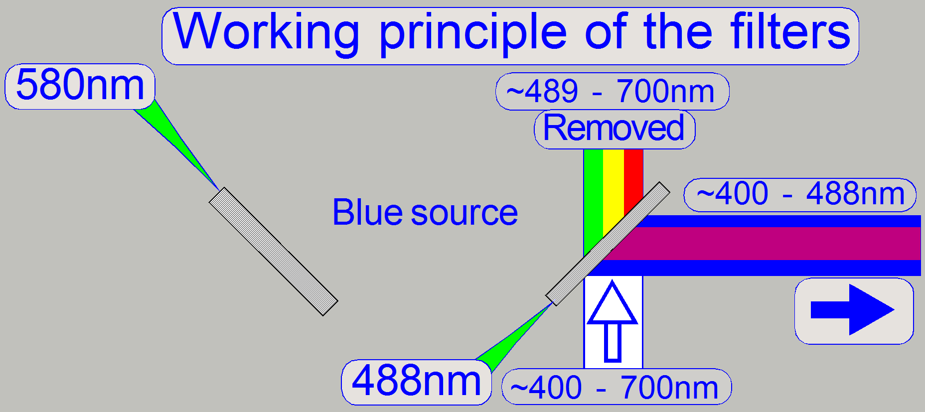 The dichroic beamsplitter would also reflecting violet light, but
because the power LED emits only blue light (from about 420nm) in practice, the
violet part does not exist.
The dichroic beamsplitter would also reflecting violet light, but
because the power LED emits only blue light (from about 420nm) in practice, the
violet part does not exist.
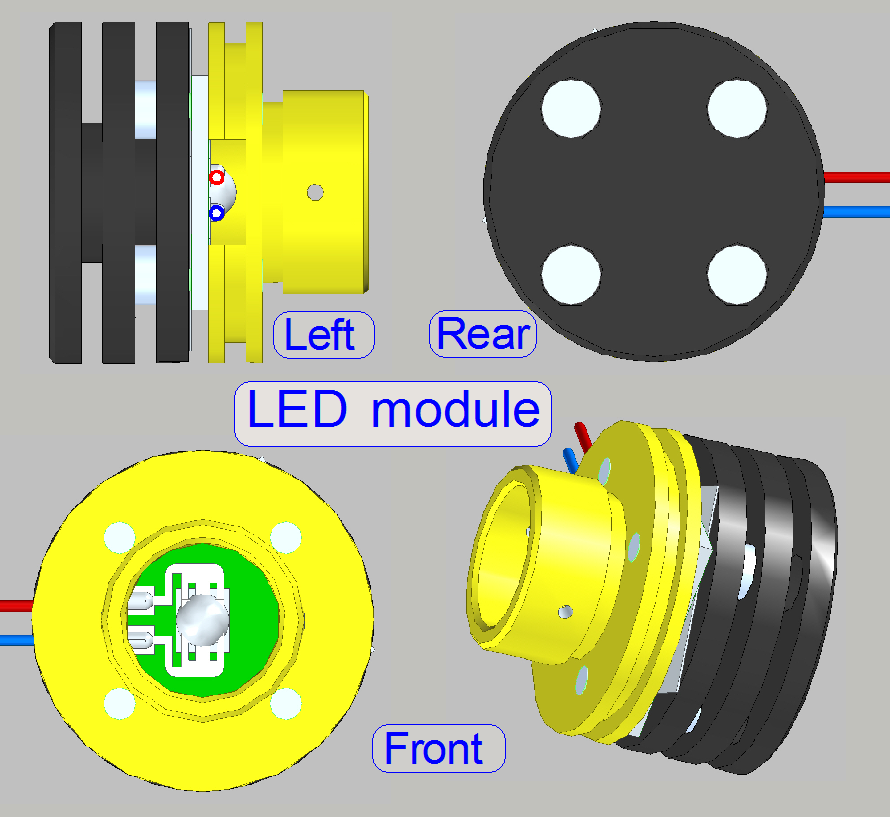
The
power led module creates white light and is used to illuminate the Field Of
View (FOV) in the brightfield scan mode.
·
Because the brightfield image is
created from the colors RGB the module exists 3 times in the brightfield illumination unit; the wire color is used to
find the appropriate connector easily.
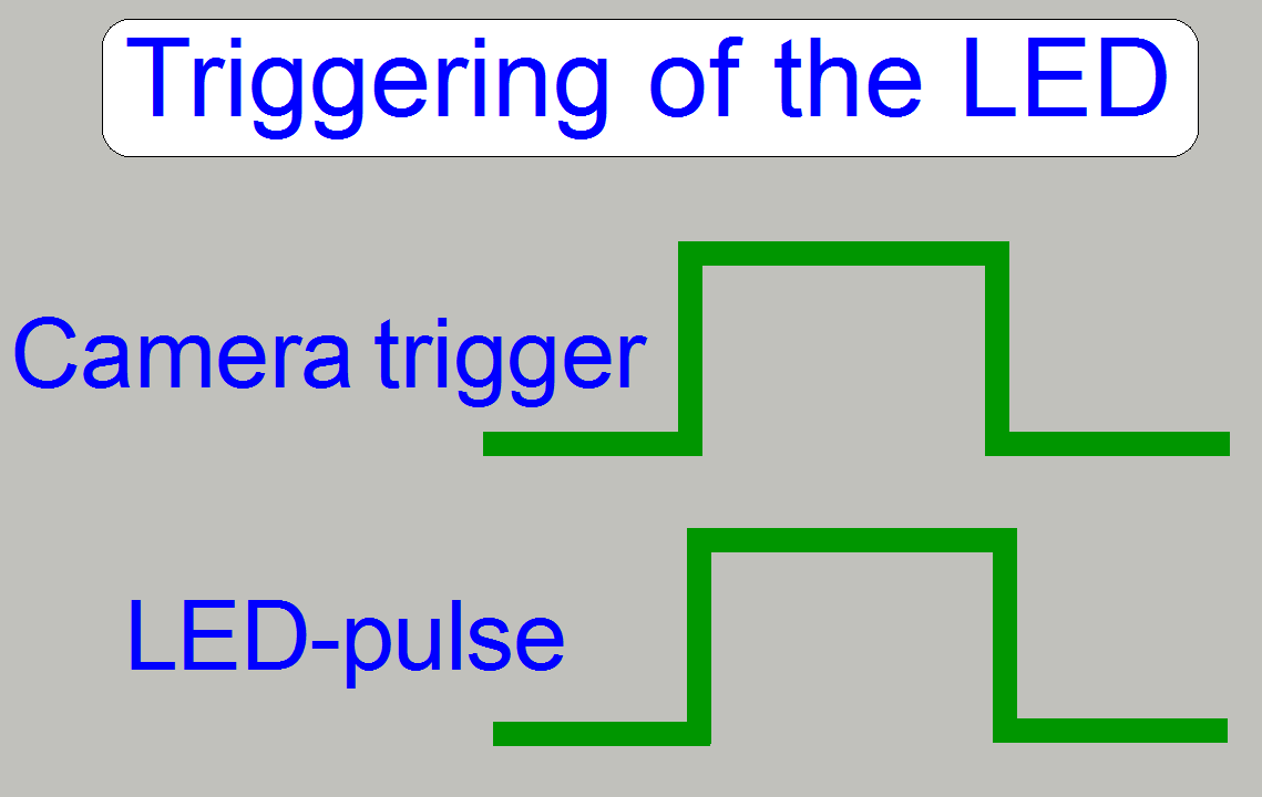
The
pulse frequency may be more than hundred Hz; it means, the scan camera can make
more than 100 images /second.
To switch on the
LED during the camera is ready; the led module is triggered (synchronized) by
the scan camera with a trigger cable or software controlled together with the
camera.
·
The
LED module is inserted into the Illumination tube until it stops!
·
Adjustments
are not required.
·
Maintenance
is not required.
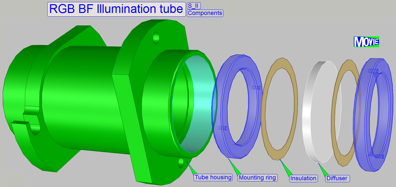
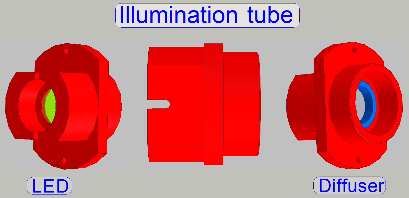 In microscopes and scanners as well,
correct illumination
of the tissue is very important. The illumination tube contains the optics to
produce light with a high density and coherent rays; so, the field of view can
be illuminated evenly.
In microscopes and scanners as well,
correct illumination
of the tissue is very important. The illumination tube contains the optics to
produce light with a high density and coherent rays; so, the field of view can
be illuminated evenly.
Because the brightfield
image is created from the colors RGB the illumination tube exists 3 times in
the brightfield illumination unit; there are no
differences in the construction.
·
The illumination tube is mounted to the Illumination unit by 2 bolts!
·
Adjustments are not required.
·
Maintenance
is not required.
·
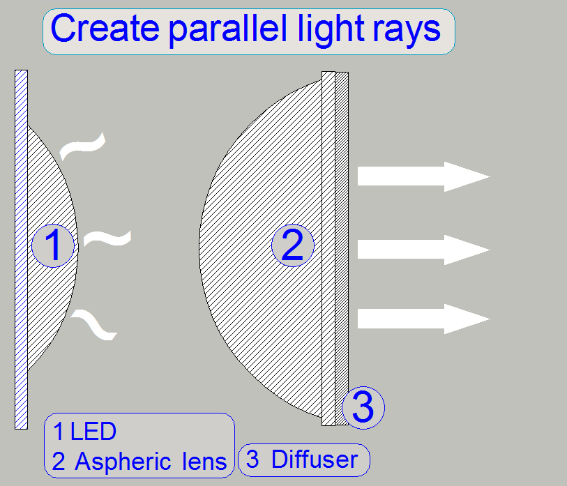 The white light, emitted by the LED will
be collected by the aspheric lens and will be arranged to parallel light rays.
The white light, emitted by the LED will
be collected by the aspheric lens and will be arranged to parallel light rays.
·
The light
rays crossing the diffuser and are send to the dichroic
beamsplitter.
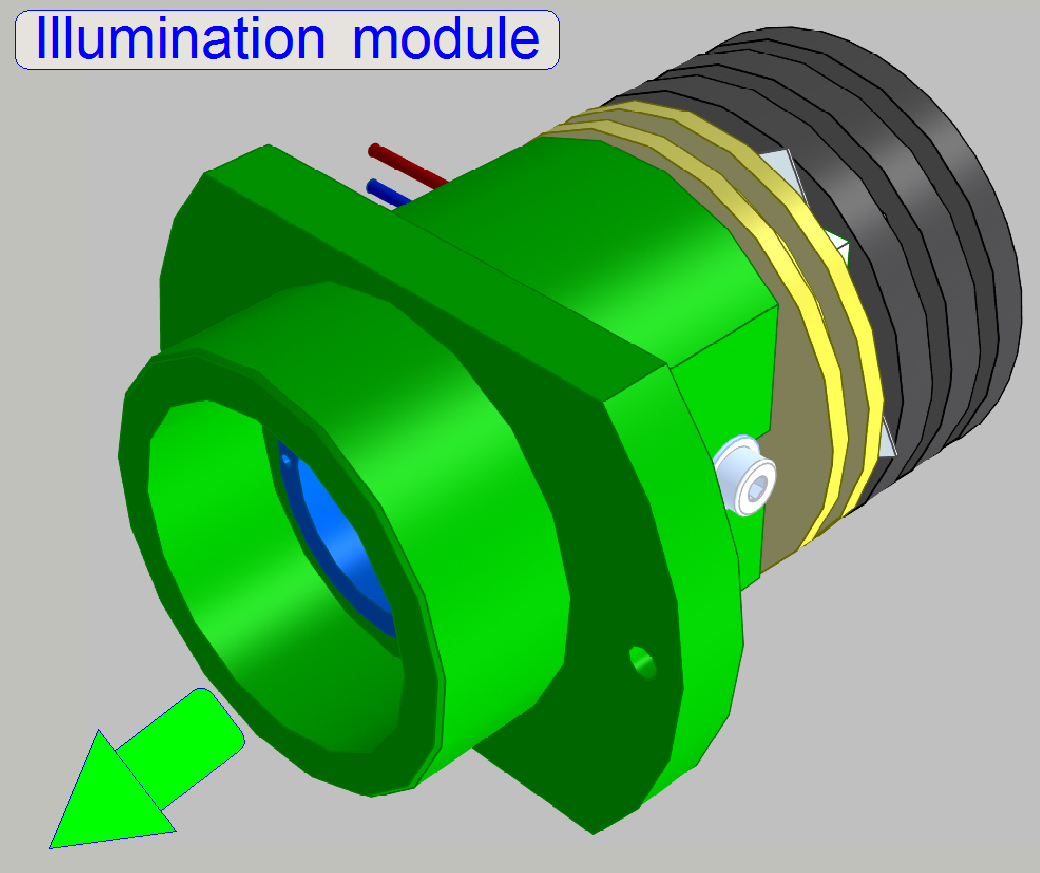 An illumination module
consists of the LED module and the illumination tube.
An illumination module
consists of the LED module and the illumination tube.
·
The
Illumination module does not contain wavelength range filtering components!
·
Adjustments
are not required.
·
Maintenance
is not required.
Watch video: Illumination module
·
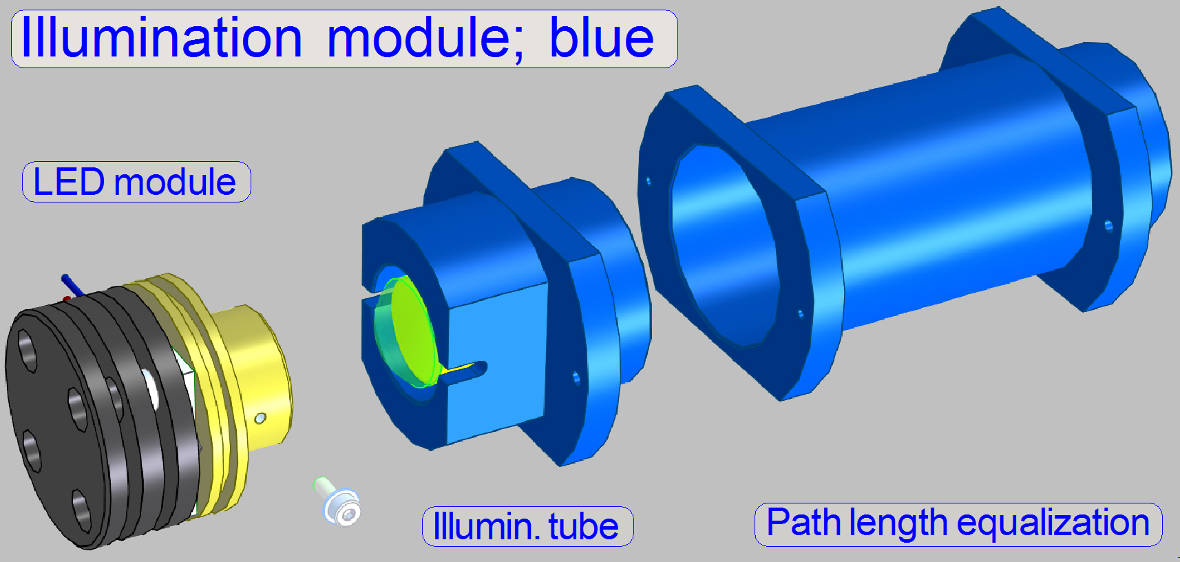 To ensure, that the
distance of the illumination module to the condenser is equal for all three
colors, the light path of blue got a light path length equalization tube!
To ensure, that the
distance of the illumination module to the condenser is equal for all three
colors, the light path of blue got a light path length equalization tube!
·
The construction does not contain wavelength range filtering
components!
·
Adjustments
are not required.
·
Maintenance
is not required.
·
 Adjustments are not required.
·
Maintenance
is not required.
Watch video: Illumination
mirror

Remark
In SCAN_II the Illumination mirror is not
required; it is replaced by the illumination tube.
·
 Connect the appropriate
cable to the specified connector
Connect the appropriate
cable to the specified connector
![]() “S_II_Power and
control” and “PCON_RGB
BF scan illumination”
“S_II_Power and
control” and “PCON_RGB
BF scan illumination”