X-Y-stage unit;
D_II
For
technicians and sales managers
This section describes the components, functionality, handling, installation
and checking instructions of the X-Y-stage unit for the scanner Pannoramic DESK
_II (D_II).
Contents
Maximal hysteresis in
Y-direction
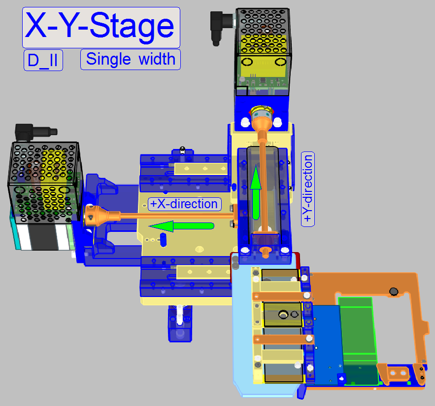
The X-Y-stage unit is used to
position the slide at loading or unloading action, it moves the slide in X- and
Y-direction during the scan process.
 The movements are
realized by stepper motors. The slide insertion is done manually, in the slide
insert and removal position.
The movements are
realized by stepper motors. The slide insertion is done manually, in the slide
insert and removal position.
The X-Y-stage unit is mounted
fixed; a remove or exchange procedure requires several checks and adjustment
procedures, so a prophylactic remove is strongly not recommended .
The exchange of the X-Y-stage unit is
possible
- If the shape
of any part is deformed or a part is broken and this can not be exchanged
separately.
- If the
X-Y-stage unit has any fault and the exchange of the unit was explicitly
recommended by 3DHISTECH's Service and Support.
- In any cases,
please refer first to the chapter 'Before you start to replace units'.
Requirements
- Service
program for slide scanners ('SlideScannerService.exe')
with the actual license file.
- Slide scanner
and Slide Viewer software ('SlideScanner.exe',
'SlideViewer.exe')
with the actual dongle.
- 1.5, 2.5, 3
and
- Hardware and
construction knowledge of Pannoramic scanners.
See also: Construction
 Warning! Do not mix
the versions of 'SlideScanner.exe' and 'SlideScannerService.exe'.
Warning! Do not mix
the versions of 'SlideScanner.exe' and 'SlideScannerService.exe'.
Always use these
programs with the same version number, otherwise the 'SlideScannerService.exe' program can produce unwanted results, and 'SlideScanner.exe' will not work correctly or even freeze.
X- and Y-Stage unit
Modifications since summer 2016
- Mounting of the X-Y-stage unit to the
scanner plate was modified, so vibration and resonance is reduced
- Using of 5-Phase
stepper motors improves smoothness of the rotor’s movement to reduce
vibration and resonance
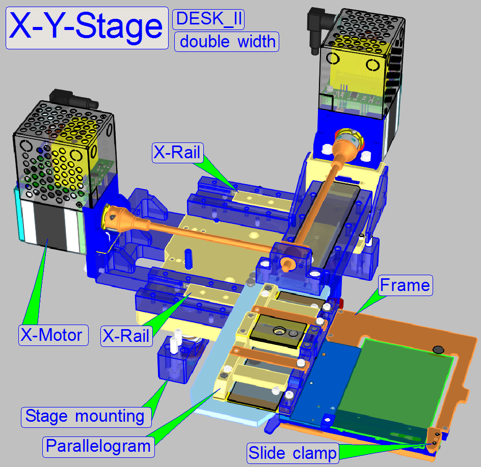
- Using of
improved X-rails increases stability in X-direction
- Newly
designed Y-rail solution increases stability in Y-direction
- Newly
designed spindle mountings allowing simplified, easily adjustments or
exchange.
- Using an
integrated, slippage-free transport module (includes transport nut and
counter nut) simplifies adjustments.
- Modifications
of the specimen holder allowing the movement of slides with a thickness of
1.2mm in the DESK_II.
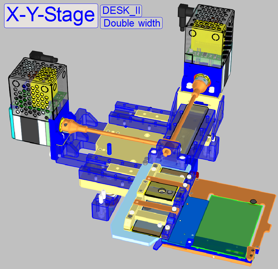
- The specimen
holder in DESK_II can also hold slides of single width (25mm) by using a
simple adapter or double width slides (50mm).
See also: Enhancements_2016
Watch video: X-Y-Stage
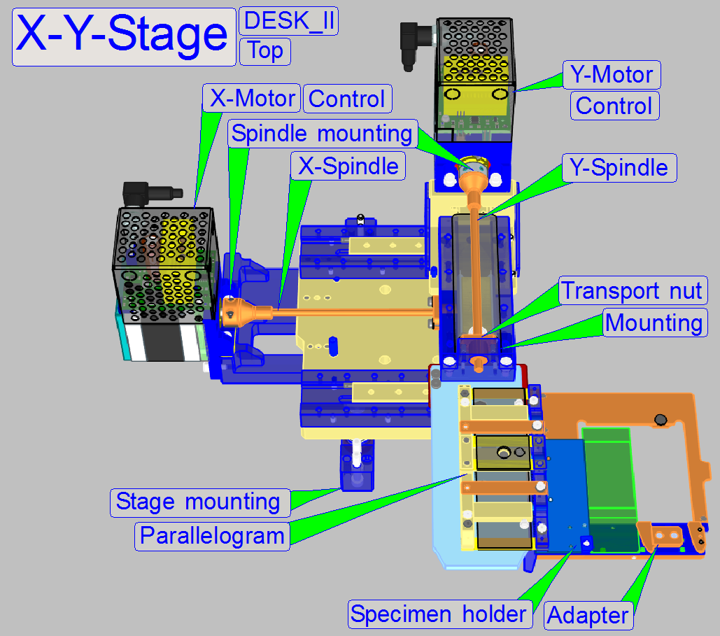
The X-Y-stage consists of the following components:
- X-motor
- Y-motor
- X-rail
- Y-rail
- X-carriage
- Y-carriage
- X-spindle
- Y-spindle
- Parallelogram
- Specimen holder
- Slide clamp
The specimen holder is
designed to hold and secure the slide during scanning operation. It also allows
inserting or removing the slide manually. This part is different in each
Pannoramic scanner and will be discussed separately.
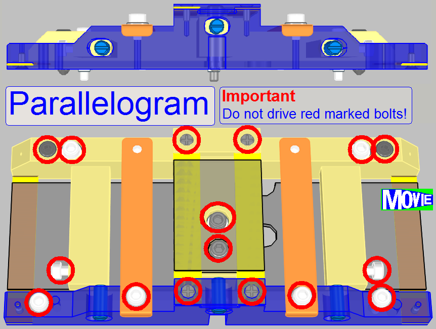
On one side of the
parallelogram the Y-carriage is mounted; on the other side the parallelogram
holds the specimen holder.
The mounting bolts of the
parallelogram and the X-direction adjustment bolt are adjusted, do not drive
them. The parallelogram and the
specimen holder are very sensitive components, because these guarantee the
perpendicularity of the X-Y-stage in relation to the optical axis (objective).
- If the parallelogram is exchanged or
dismounted and remounted, or the position of the mounting- and adjustment
bolts was altered, extensive adjustments might be required.
Remark Do not adjust the parallelogram in the field, if
possible.
Watch slide show: Parallelogram
![]() How to adjust the parallelogram
How to adjust the parallelogram
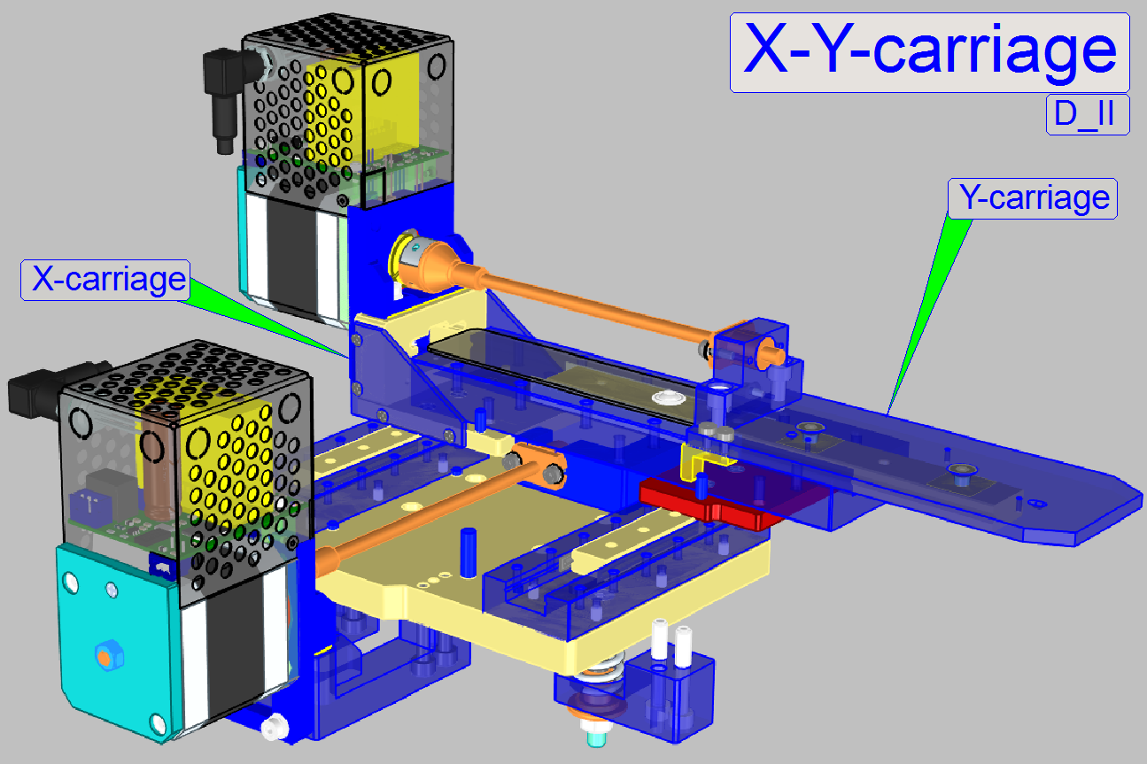
The rotor drives the transport
nut through the spindle. The transport nut is mounted to the carriage that is
moving on the rails. The X-carriage contains the entire Y-unit. The Y-carriage
moves the parallelogram with the specimen holder.
· The achieved
resolution in X- and Y-direction is: 1μm/rotor
step
· The movement range
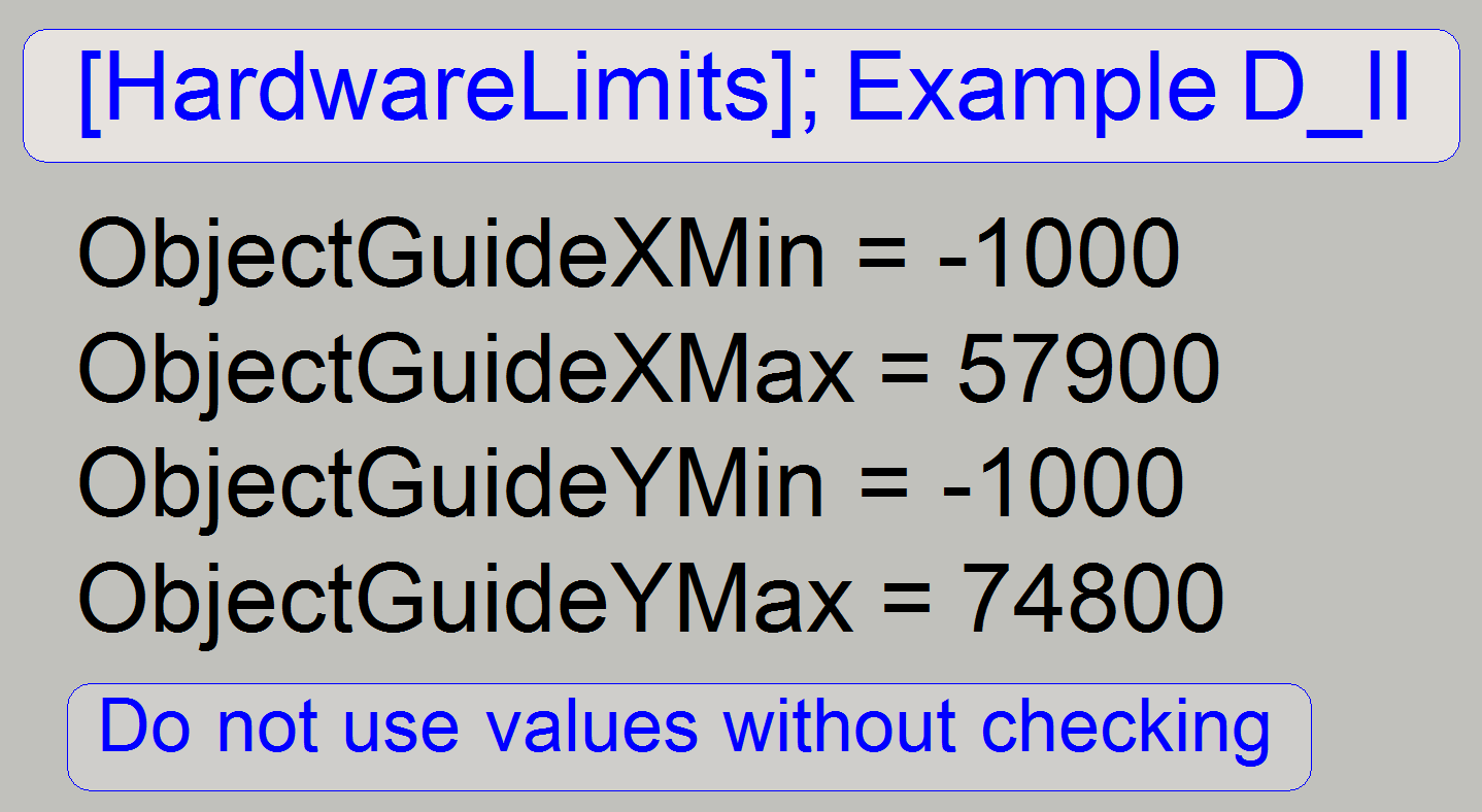
of the X-carriage is 57600 rotor steps (it means 57.6mm); see also 'HW-Limits'
· The movement range
of the Y-carriage is 73600 rotor steps (it means 73.6mm); see also 'HW-Limits'
· The parts and
units of the carriages do not need maintenance.
Watch video: X-Y-carriage; D II
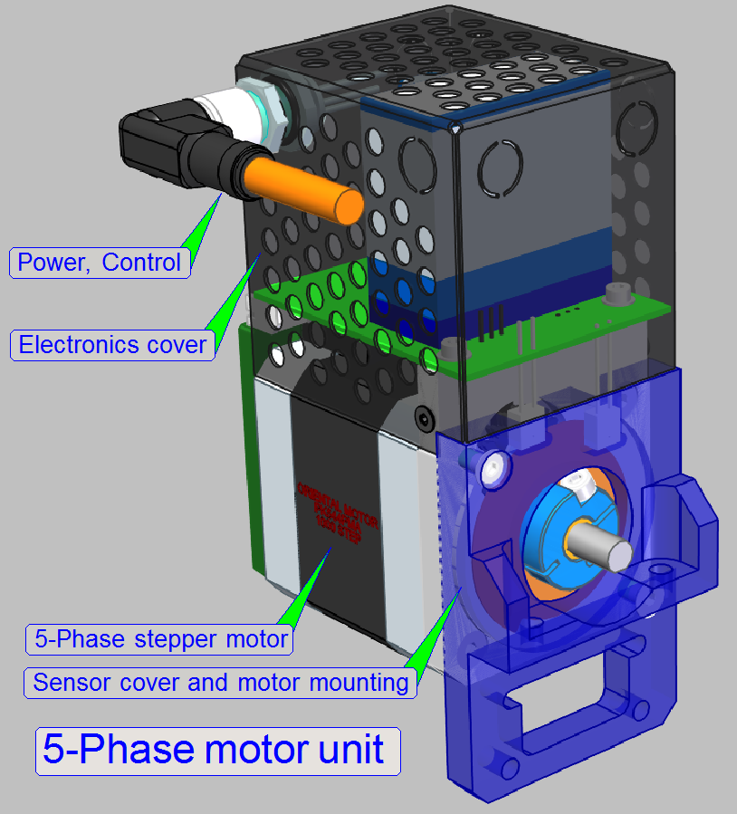
All stepper motors in the Pannoramic scanners are driven in micro
stepping mode. One revolution of rotor axle is divided into 3200µ-steps. The
forward direction of the motor axle is counter clockwise (CCW). The
construction of the mechanical X- and Y-drive together with the resolution of
the rotor movement allows a very precise movement of the specimen.
· The address of the
X-motor is 03.
· The address of the
Y-motor is 04.
Note! The parts of the stepper
motor do not need maintenance or mechanical adjustments.
For more information, see
chapters 'Stepper motor', 'Addresses' and 'Cabling of addressable
units'.
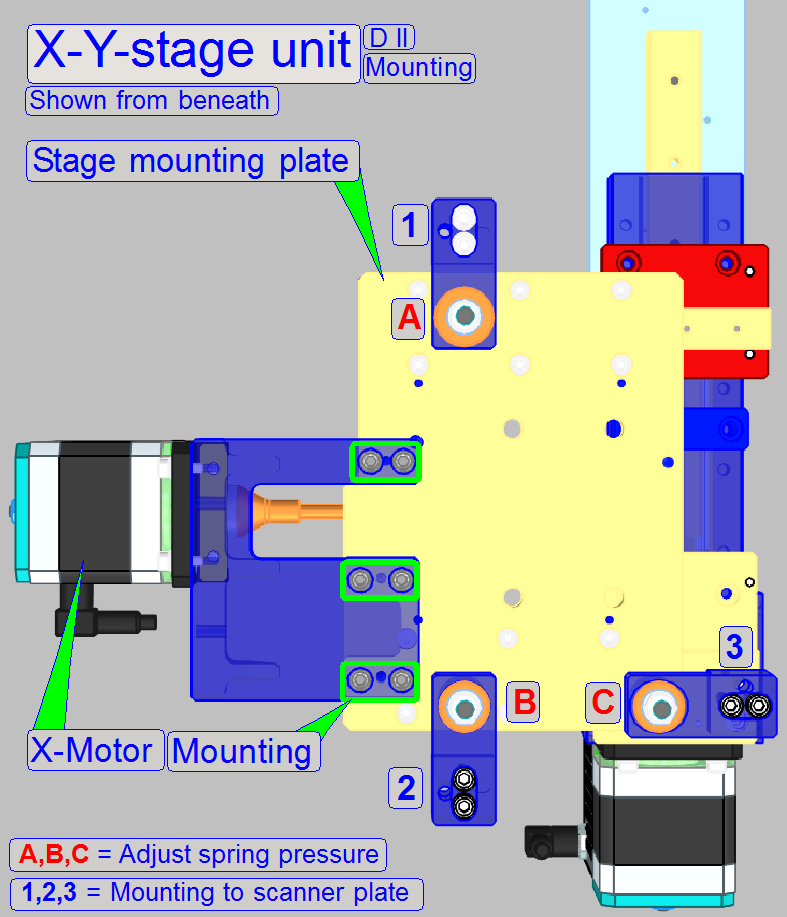
Important
In DESK_II the X-Y-unit is
not designed for easily removing and reassembling.
·
Never drive the spring pressure adjustment nuts
A, B and C!
Spring pressure adjustment
The pressure of the springs is adjusted, so an effective vibration and
resonance removal is ensured and this improves high quality of the scanned
tissue. To reach this, the pressure spring force and the inclination of the stage
unit is adjusted with special tools.
Furthermore, the position of the spring pressure nut affects also the
inclination of the X-Y-stage unit in relation to the optical axis!
· Please
do not drive these nuts!
Unit mounting bolts
If the unit should be dismounted, please remove only the bolts, shown as
1, 2 and 3.
Remove the X-Y-stage unit
Important
In DESK_II the X-Y-unit is
not designed for easily removing and reassembling.
Please do the following
procedure only, if the remove of the X-Y-stage unit is unavoidable!
·
Never drive the spring pressure adjustment nuts A, B and C (see
mounting, above)!
1.
Move the X-stage
to Home1,2.
2.
Move the X-motor by +28000 steps.
3.
Move the Y-stage to Home1,2.
4.
Move the Y-motor by +70000 steps.
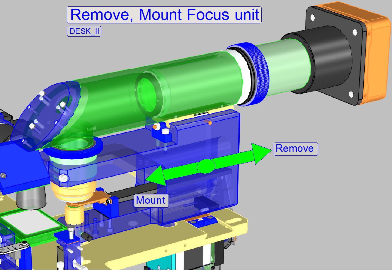
5.
Loosen the focus unit fixing bolt by turning it
clockwise.
6.
Disconnect the cables of the focus motor and the X-Y-stage unit.
7.
Remove the focus unit.
8.
Remove the bolts 1,2 and 3 and remove the X-Y-stage
unit.
9.
To remove the X-Y-stage unit upward, the L-shaped
mounting elements may be rotated by 90°.
10.
Remove the X-Y-stage unit upward.
See also: Dismount the focus unit
X-Y-unit mounting above
1.
Insert the X-Y-stage unit into the cutout of the
scanner plate and rotate the L-shaped mounting elements into the mounting
position.
2.
Drive in the mounting bolts and tighten these.
3.
Connect the cables of the X-Y-stage unit..
4.
Insert the focus unit until it stops.
5.
Tighten the fixing bolt by turning it counter
clockwise.
6.
Connect the cable.
The carriages are used to
move the specimen holder and so the slide in X- and Y-directions.
The unit mounting plate is
mounted to the scanner plate from beneath. This ensures the proper mounting and
fixing of the X-Y-stage unit.
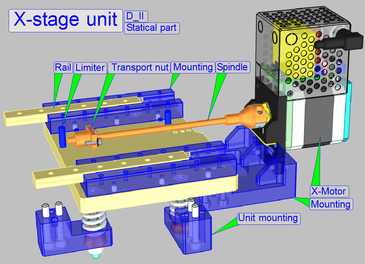
The static part of the X-stage consists of:
- X-direction mounting plate
- X-motor
- Dovetail foot (mounted from beneath)
- X-rails
- X-minimum limiter
- X-maximum limiter
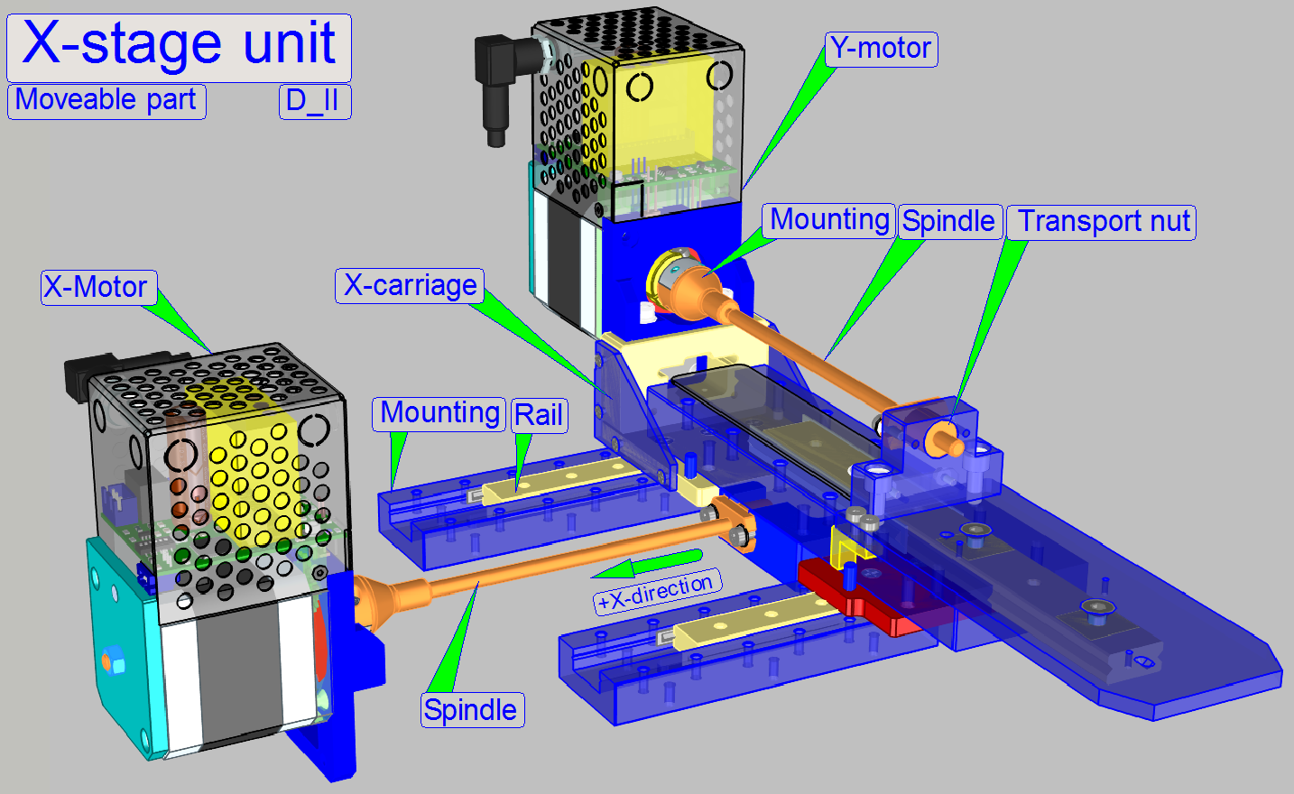
The moveable part of the
X-stage consists of:
- X-stepper rotor
- Spindle
- Transport nut (module)
- Y-stage unit
The transport nut module is
driven by the spindle and is mounted onto the Y-stage unit (the X-carriage).
Watch video: X-Carriage; D II
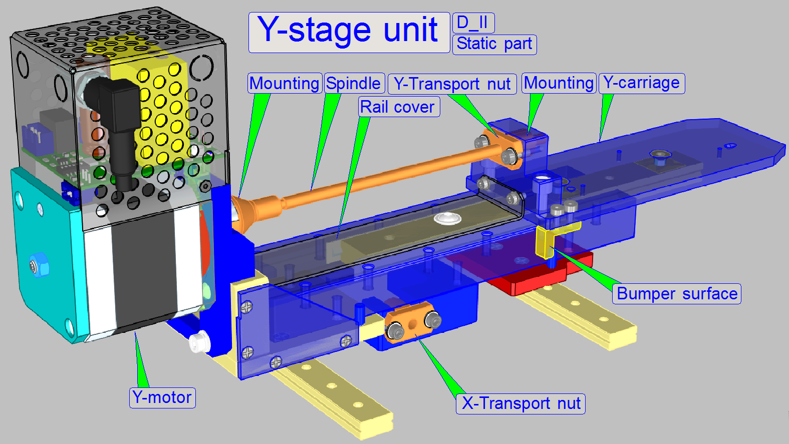
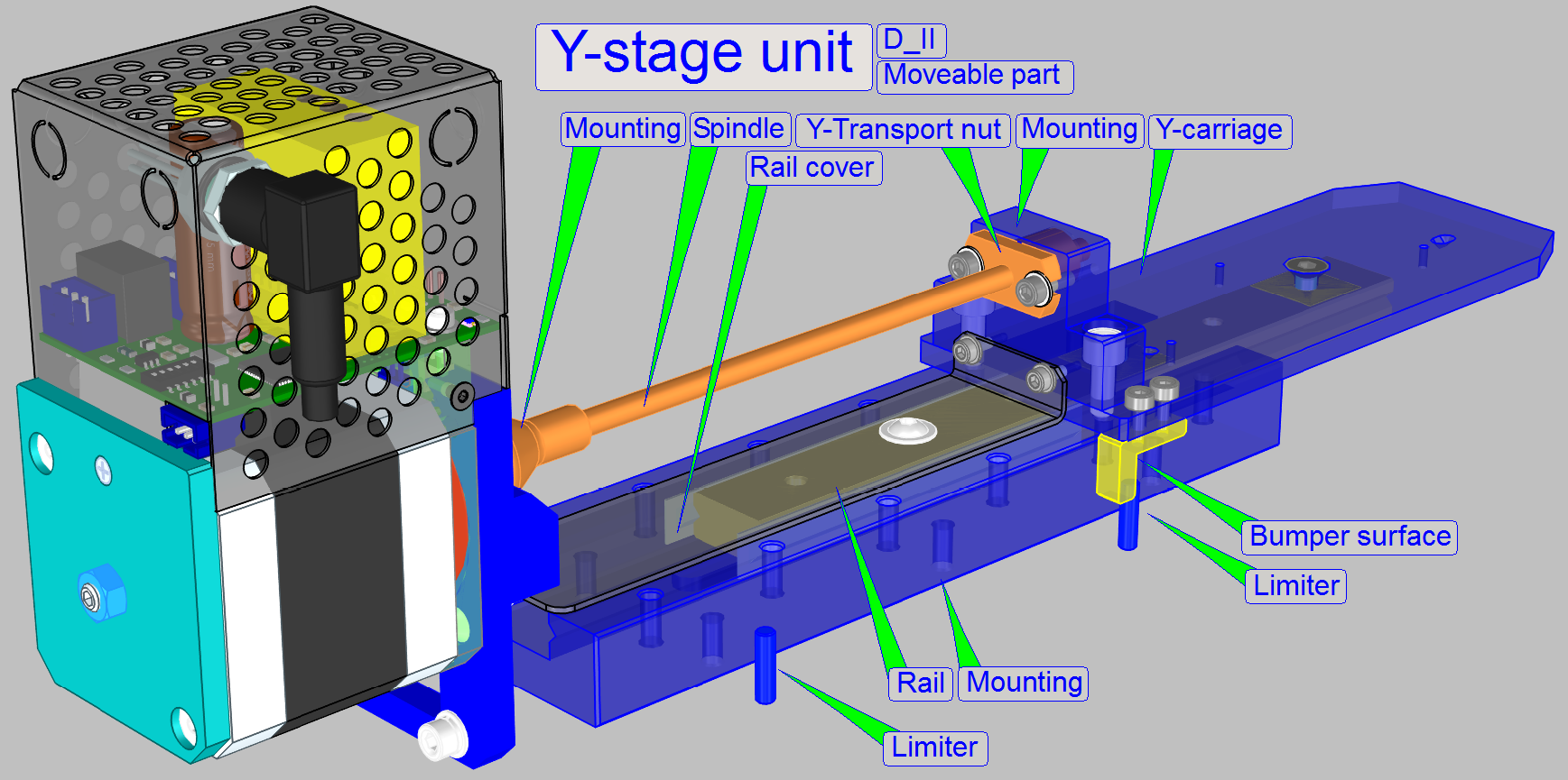
The static part of the
Y-stage consists of:
- Y-direction mounting plate (X-carriage)
- Y-motor
- Y-rails
- Y-minimum limiter
- Y-maximum limiter
The Y-motor is mounted to the
mounting plate.
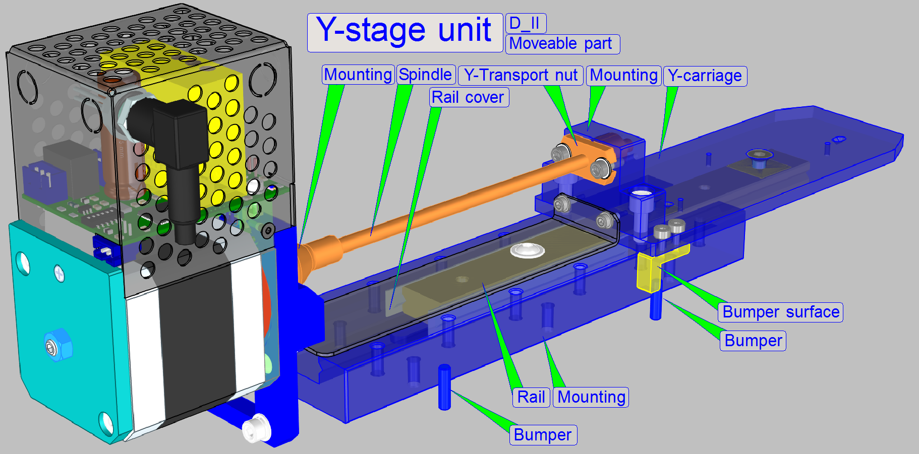
The moveable part of the
Y-stage consists of:
- Y-stepper rotor
- Spindle
- Transport nut
- Y-carriage
- Parallelogram
- Specimen holder
The transport nut is mounted
to the Y-carriage.
Watch video: Y-carriage; D II
The carriages are mounted and
lead with rails for each direction.
The X- and Y-rails ensures a
slippage-free movement of the carriages in X- and Y-direction. The X-carriage
contains the entire Y-part. When the motor starts rotating, the spindle, it
drives the carriage in the direction, defined by the rotating direction of the
rotor. The mechanical dimensioning of the X-Y-stage allows reaching nearly each
part of the slide by the objective, except the barcode area (restrictions are
given by the slide holding mechanics of the specimen holder; see
also the scan area).
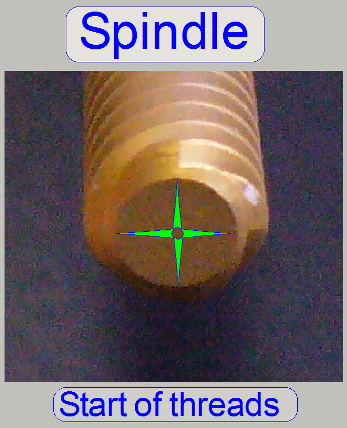
 The spindle
(together with the transport nut module) is used to transform rotation of the
rotor into slippage-free longitudinal movements. The four threads on the
spindle guarantee a precise movement, increase the torque of the mechanical drive
and help to reduce or eliminate slippage and hysteresis.
The spindle
(together with the transport nut module) is used to transform rotation of the
rotor into slippage-free longitudinal movements. The four threads on the
spindle guarantee a precise movement, increase the torque of the mechanical drive
and help to reduce or eliminate slippage and hysteresis.
The X- and Y-spindle are
connected to the
stepper motors by the help of the spindle mounting. On the thread of the
spindle the transport nut module is situated and this is mounted onto the
X- respective Y-carriage. To eliminate slippage in the connection between rotor
axle and spindle mounting, the spindle mounting is hold on the motor axle by a
pressure connection.
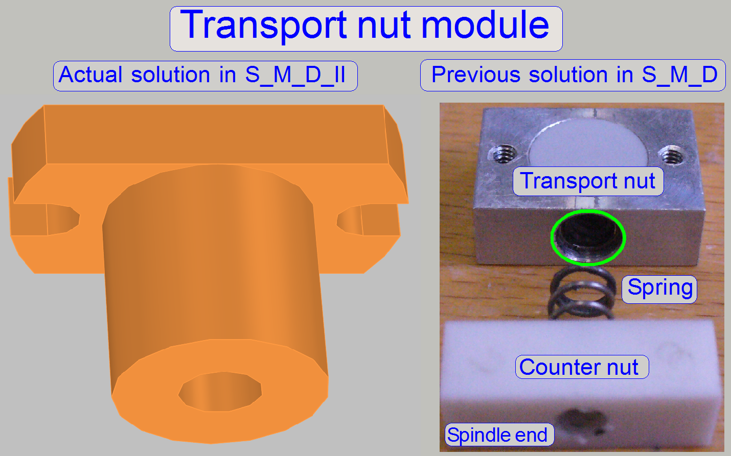
The construction of the
carriage transport nuts ensures a slippage-free movement of the carriages. The early
used transport nut solution with transport nut, spring and counter nut is now
replaced by an integrated module solution. Adjustments, regarding the counter
nut position are now done by rotating the spindle separated from the motor axle
(e.g. if the motor axle stays in Home 1,2). This way, the hardware limits may
be adjusted easily and more precise.
The use of the stepper motors
micro stepping mode, combined with the accuracy of the mechanics allows
achieving a resolution of 1µm longitudinal movement per rotor step.
The movement range of each
carriage is limited by two limiters, one for the upper and one for the lower
limit. Limiters are used for both, the X- and Y-directions. With the limiters the
mechanical construction gets a start and an end position.
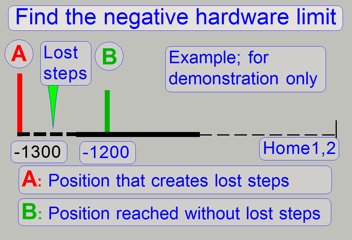
When the mechanical limiter
is reached by the carriage, the carriage movement stops. If more steps are
entered in the service program, those steps are lost - this behavior creates
'lost steps'.
- The defined limit position is a part of the real
movement range!
During the detection of the
hardware limits the creation of lost steps is used to find and determine the
upper and lower hardware limits. The first number of steps that do not create
lost steps is used as hardware limit; the accuracy is 100 steps (0.1mm).
Example:
· If the step number
of 1200 steps in negative direction after Home1 and Home2 does create lost
steps (more than +-2 steps) and
· The step number of
1100 steps in negative direction after Home1 and Home2 does not create lost
steps (not more than +-2 steps) the negative hardware limit will be -1100
steps.
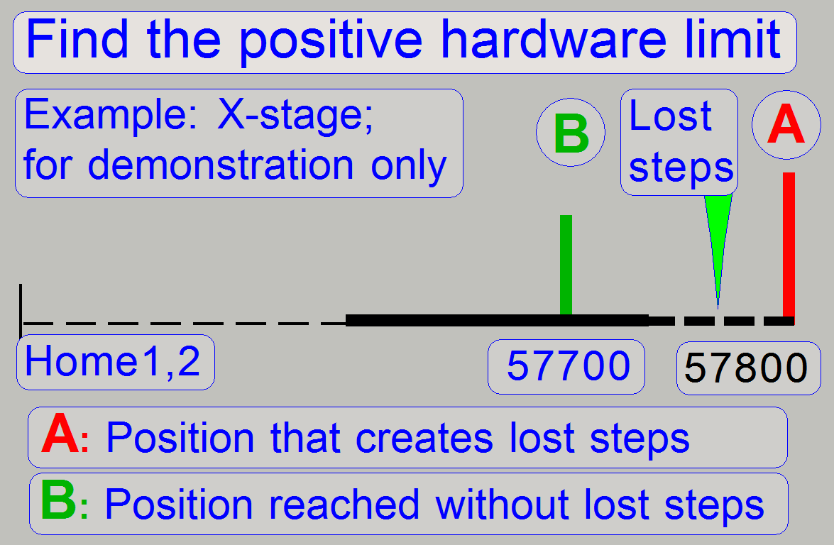
To define the upper limit,
the same principle is used. First we create lost steps then we decrease the
number of steps to go by 100 steps until no steps are lost during the movement.
During slide insertion or removal actions and sample scanning process
lost rotor steps are unwanted, because the counting and reporting of steps
mismatches the real number of steps gone. Therefore, the limits are defined by
using the last possible number of steps without lost steps and an accuracy of
100 steps (=0.1 mm).
For more information, see chapter 'Adjustment
procedures'.
The home position does not
define the mechanical limit. Either in -X- and in -Y-direction there are
several hundred more steps possible. The absolute limits are defined as shown
in the figures 'X-direction; D_II'
and 'Y-direction; D_II'.
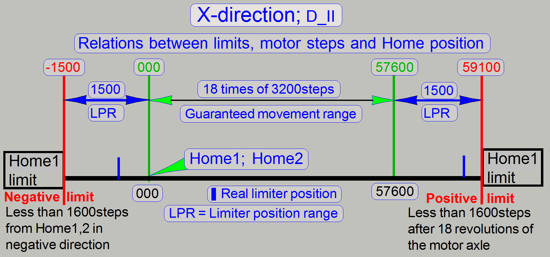
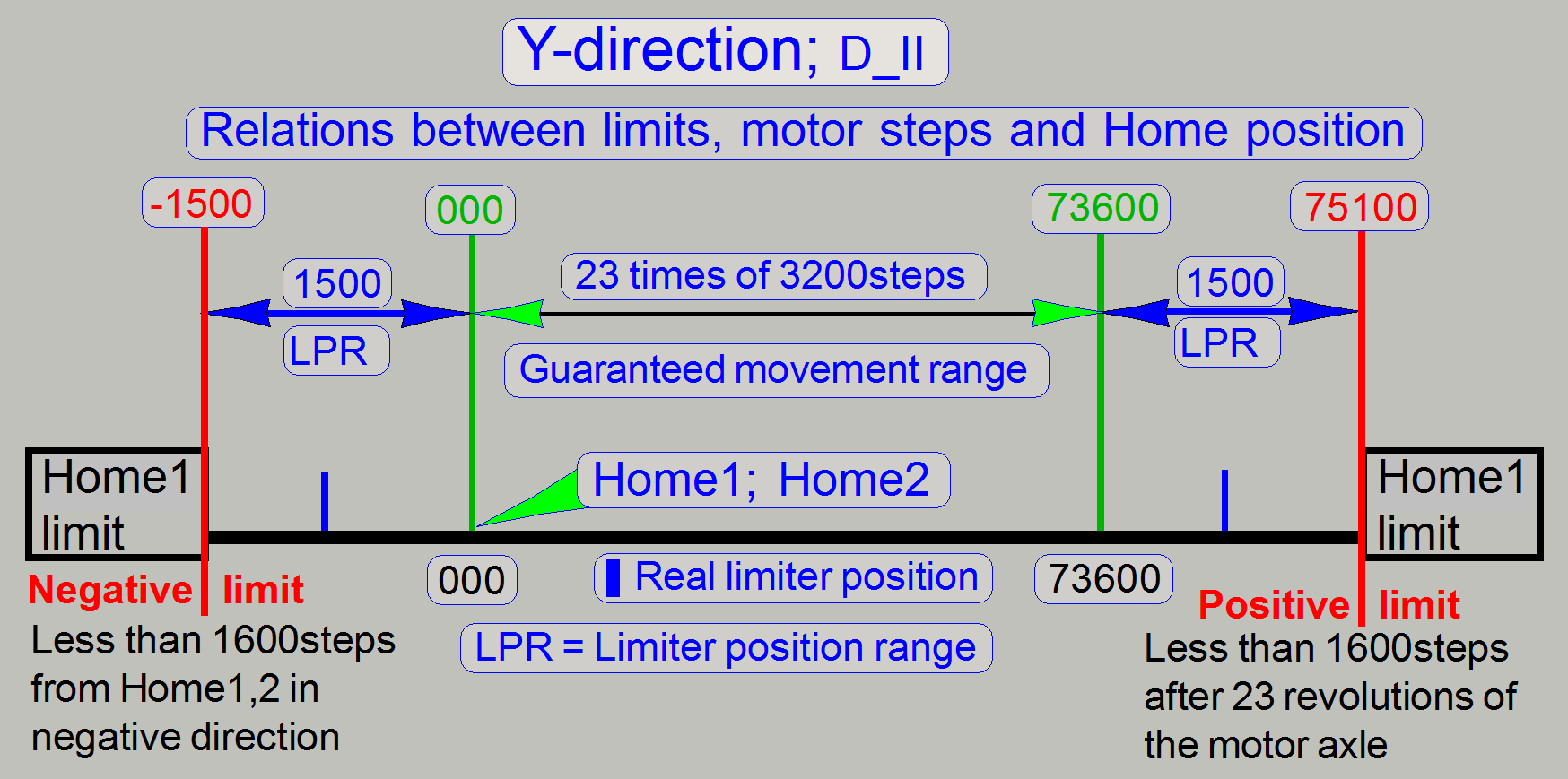
Note! The unit (or its
adjustment) is faulty, if there are more than 1600 steps possible in negative direction
from Home 1,2.
The unit (or its adjustment)
is faulty, if there are more than 1600 steps possible in positive direction
after 57600 steps in +X-direction or 73600 steps in +Y-direction.
For more information, see chapters 'Adjustment
procedures', 'How to
define the hardware limits' and 'Check or define the hardware limits of the
X-Y-stage unit'.
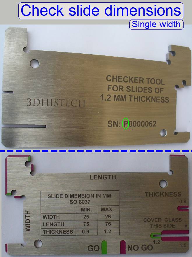 Single width
Length: 75.00 to
Width: 25.00 to
Thickness: 00.95 to
Double width
Length: 75.00 to
Width: 50.00 to
Thickness: 00.95 to
- If the first character of the serial number is an
“S” the tool is used to check the slide dimensions of
single width slides; thickness = 0.95 ... 1.05mm.
- If the first character of the serial number is a “P” the tool is used to check the
slide dimensions of single width slides; thickness = 0.95 ... 1.20mm.
- Please check the slide dimensions before insertion
of slides!
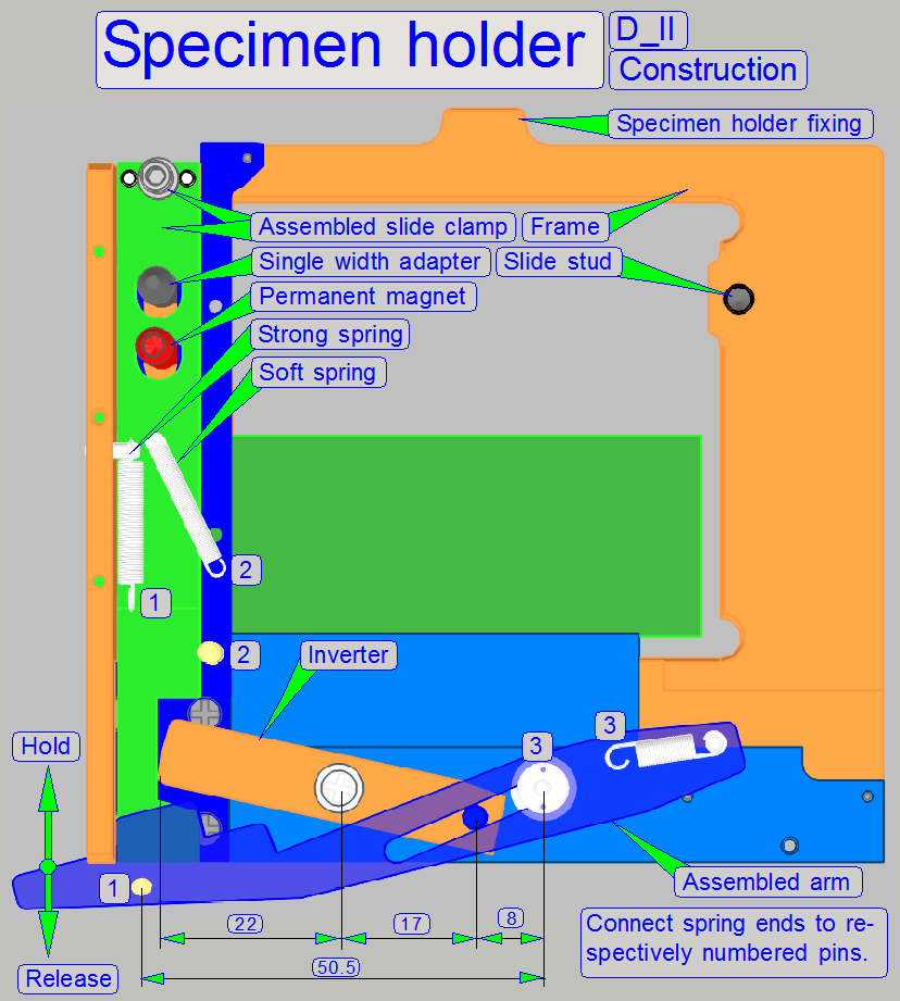
During scanning, the assembled arm is not
in contact with the release pin and so, the assembled arm is in the 'Hold'
state. The slide is tightened by the 'Strong spring' to ensure, that the slide
does not change its position in the frame. The force of the 'Strong spring' is
2N ±0.5N. Through the 'Assembled arm' and the 'Inverter', the 'Strong
spring' forces the 'Assembled clamp' sideward (in the image downward) in
relation 50.5 : 8 (the 'Assembled
arm' amplifies the force of 'Strong spring') and in relation 17:22 the
'Inverter' attenuates a little bit this force, but its main task is, to invert
the movement. This way the force of the slide clamp against the slide is nearly
five times more than the force of the 'Strong spring'.
During slide
insert and removal operations, the 'Assembled arm' is moved sideward
against the Release pin and so, the mechanics, driven by the 'Assembled arm'
releases the 'Slide clamp' (Adapter) via the 'Inverter' mechanics. Only the
force of the 'Soft spring' holds now the slide in the frame. Because the force
of the 'Soft spring' is not much, the slide can be inserted or removed
manually.
·
Please do not exceed the allowed slide dimensions;
otherwise, the slide clamp may be damaged!
Watch video: Release pin and supporter
Slide holding and scan area
The slide is hold by the specimen holder on the longer, lower edge and
with a slide clamp on its upper edge, on the barcode area; see the red lines on
the right. As you can see, the definition of the limits X-min and Y-max are
critical. X-max and Y-min are given by the maximal usable slide size and are
not critical; they could be the slide edge.
·
Never touch the specimen holder with the
objective or the focus pin during movements!
See also: 'Areas
of the slide', and 'Define
the scan area''
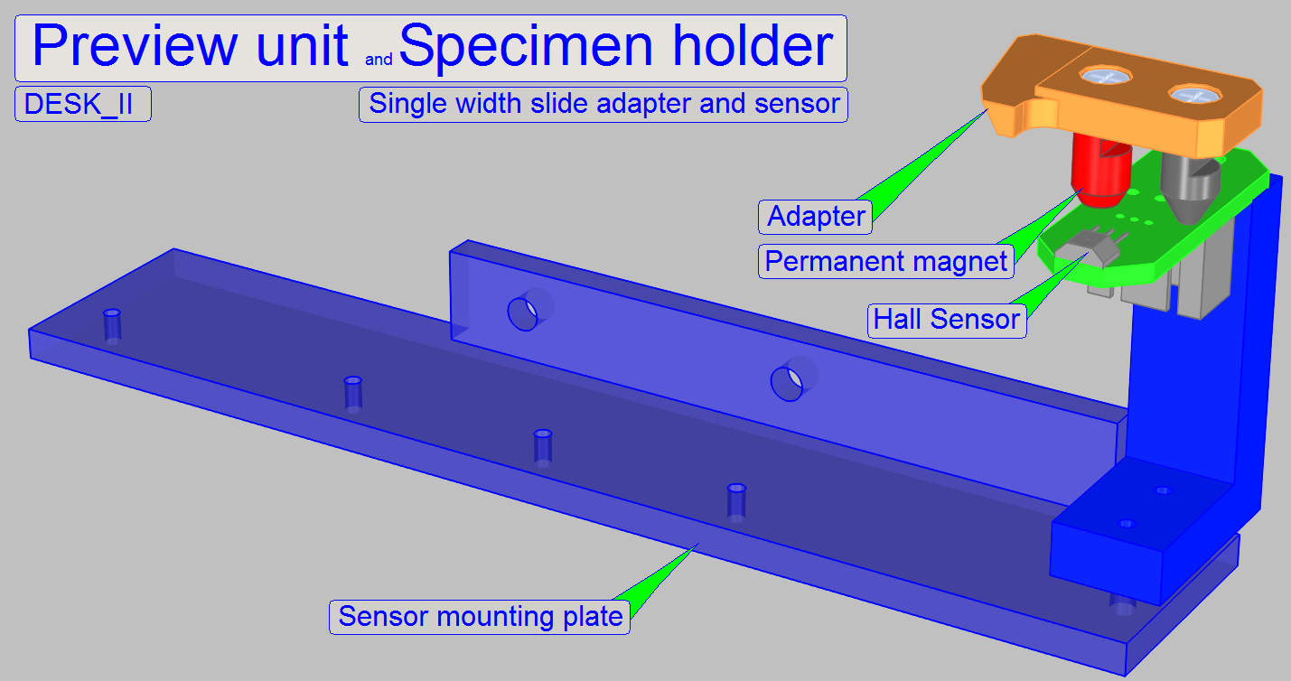 Single width slide
adapter and sensor
Single width slide
adapter and sensor
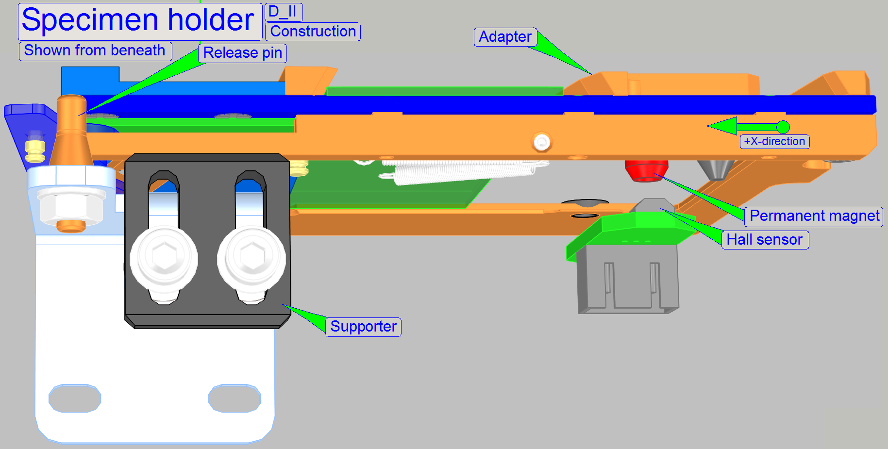
As mentioned above, the specimen holder may hold slides with single
width and double width.
If single width slides should be inserted into the specimen holder an
adapter is used.
To tell the software, that the adapter is present, a Hall sensor,
mounted on the preview unit's sensor mounting plate is used.
If the sensor shows the active state in the slide insert position, the
adapter is present, slides with single width will be inserted.
Adjustment
Move the X-Y-stage with the service program to the Home1,2 position and
insert and remove the adapter more times. During these actions, the presence or
absence of the adapter have to be signaled surely and correctly.
- Check this behavior
more times.
If checks failed, adjust the sensor position more precise
Adjustments for the X-Y-carriage unit
The following procedures are described
for Pannoramic SCAN especially. In Pannoramic MIDI and Pannoramic DESK the
adjustments are logically identical, but some pronunciations like 'up or down
and left or right, horizontal and vertical' may differ. Please take this into
account if you are adjusting DESK or
Find the hardware limits
for the X-carriage
·
This procedure must be done
if the scanner unit or the X-Y-stage was changed; the parallelogram was
adjusted, the specimen holder mounting was altered or the drive unit was
manipulated.
· Insert a medium large slide and set the focus
motor to 500 steps.
See also: 'How to define the hardware limits'.
Find the negative limit
in -X-direction
1. With the service program set
the Y-carriage to Home1,2.
2. Set the X-carriage to
Home1,2.
3. With the service program go
forward to the X-motor position -1200 steps.
4. Go backward +1200 steps.
5. Press Home1 (only). There should
be not more then +-2 steps difference to Home1. If there are more steps lost,
decrease the actual absolute number of steps by 100 and repeat from step
6. If there are not more then 2
steps difference to Home1, increase the number of steps by 100 and repeat from
step
7. The negative limit is found
correctly if the motor movement has no steps lost and the actual absolute
number of steps, increased by 100 would produce lost steps. The found negative
limit can differ by more 100 steps from unit to unit. The reason is the
tolerance of the components.
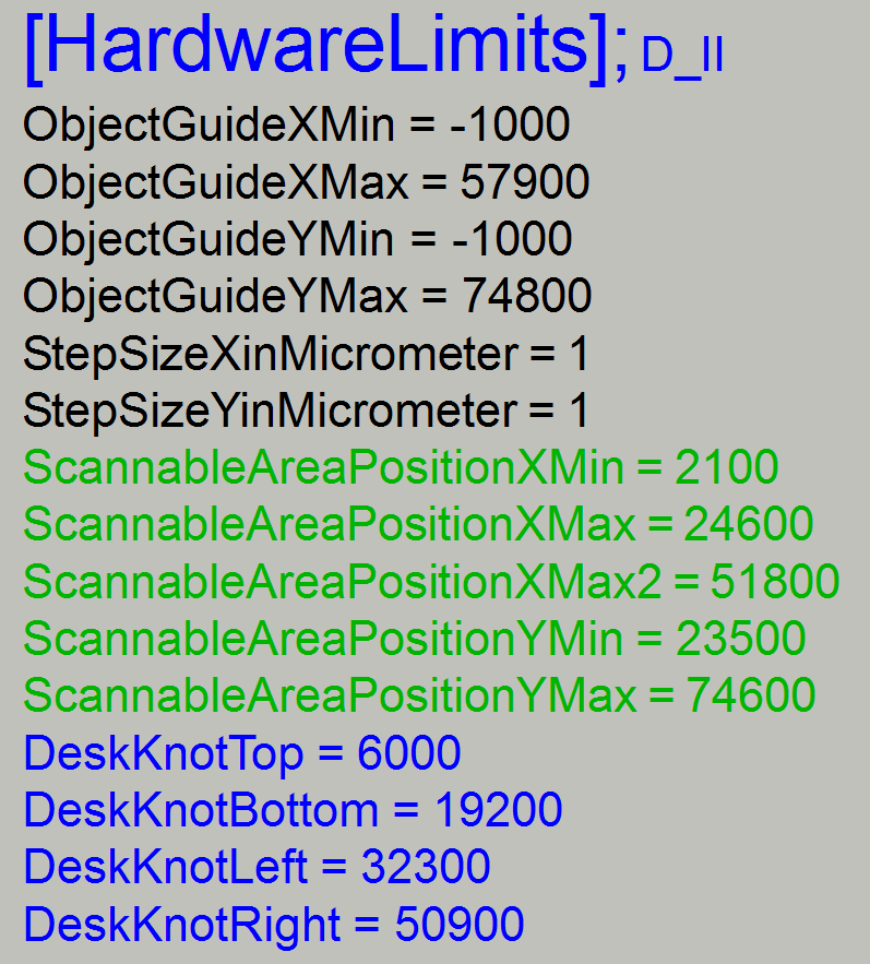
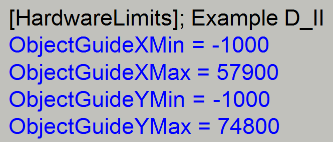
8. Update the value of the
parameter 'ObjectGuideXMin' with the found number of the actual steps in the
file 'MicroscopeConfiguration.ini' section [HardwareLimits] and save the file.
Find the positive limit
in +X-direction
With the service
program set the X-carriage unit to Home1,2.
9. Go forward to the X-motor
position +29700 steps.
10. Go backward 29700 steps.
11. Press Home1 (only). There should be not more
then +-2 steps difference to Home1. If there are more steps lost, decrease the
actual number of steps by 100 and repeat from step
12. If there are not more then 2 steps difference to
Home1, increase the number of steps by 100 and repeat from step
13. The positive limit is found correctly if the
motor movement has no steps lost (max. 2 steps) and the actual number of steps,
increased by 100 would produce lost steps. The found positive limit can differ
by more 100 steps from unit to unit. The reason is the tolerance of the
components.
14. Update the value of the parameter
'ObjectGuideXMax' with the found value in the file
'MicroscopeConfiguration.ini' section [HardwareLimits] and save the file.
·
Check the found limits by using the number of steps,
used as parameter value in the file 'MicroscopeConfiguration.ini' section
[HardwareLimits]. Lost steps must not occur.
Find the hardware limits for the Y-carriage
For SCAN: Move the X-carriage +29000
steps from Home1,2; this way, the slide tightener can not collide with the
magazine unit and the focus pin does not collide with the lower edge of the
specimen holder.
For
For DESK: Move the X-carriage
+6400 steps from Home1,2; this way, the focus pin does not collide with the
slide stud or the slide rails of the specimen holder.
Find the negative limit
in -Y-direction
Repeat the steps,
described in the procedure above 'To find the negative limit in -X-direction'
logically with the Y-carriage.
15. Update the value of the parameter 'ObjectGuideYMin'
with the found number of the actual steps in the file
'MicroscopeConfiguration.ini' section [HardwareLimits] and save the file.

Find the positive limit
in +Y-direction; DESK_II
Repeat the steps,
described in the procedure above 'To find the positive limit in +X-direction'
logically with the Y-carriage. The positive limit is found correctly even
before the +Y-limit is reached or before the specimen holder will be touched.
16. Update the value of the parameter 'ObjectGuideYMax'
with the found value in the file 'MicroscopeConfiguration.ini' section
[HardwareLimits] and save the file.
Further
information can be found in: 'How to define the hardware limits'.
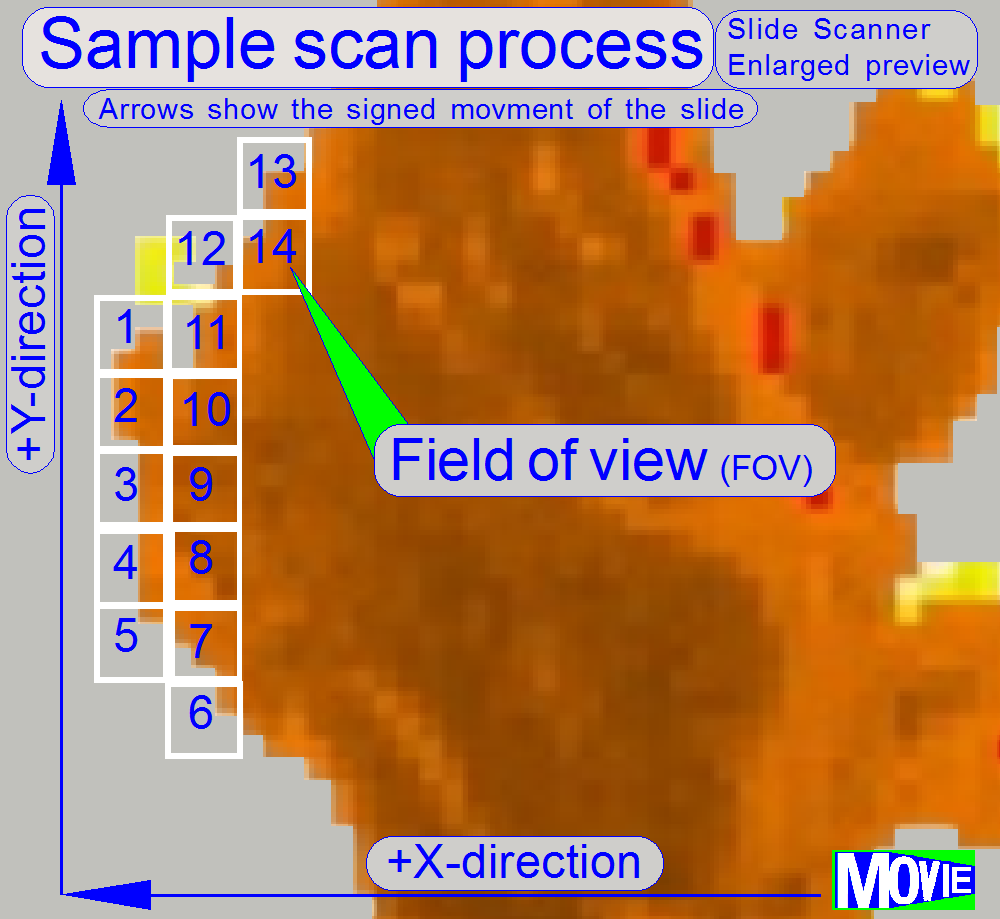 The software divides the sample to
be scanned, seen by the preview camera into fields of views; the size of the
FOV depends on the resolution of the scan camera and the magnification of the
camera adapter. Each field of view contains a small part of the neighbor FOV.
In this way, stitching becomes possible. Because the capturing of the FOV’s is
done on a meandering course, the Y-direction is often changed. If the
hysteresis in Y-direction is too much, stitching will not work correctly;
therefore, we have to check the hysteresis in Y-direction. The maximal allowed
hysteresis is 4μm (=4 motor steps). We comment that this hysteresis
decreases itself by some motor steps after some sample scan procedures, even if
the X-Y-stage is brand new.
The software divides the sample to
be scanned, seen by the preview camera into fields of views; the size of the
FOV depends on the resolution of the scan camera and the magnification of the
camera adapter. Each field of view contains a small part of the neighbor FOV.
In this way, stitching becomes possible. Because the capturing of the FOV’s is
done on a meandering course, the Y-direction is often changed. If the
hysteresis in Y-direction is too much, stitching will not work correctly;
therefore, we have to check the hysteresis in Y-direction. The maximal allowed
hysteresis is 4μm (=4 motor steps). We comment that this hysteresis
decreases itself by some motor steps after some sample scan procedures, even if
the X-Y-stage is brand new.
Because the X-direction is
never changed during a sample scan process, the X-hysteresis is not critical
and can be some steps more (max: 8 steps).
Watch video: 'Tissue scan process' (P250)
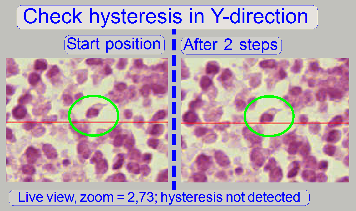
Check the maximal
hysteresis in Y-direction
 Start the program
'SlideScanner.exe' with the service password. In the tab 'Focus' produce a
sharp live view.
Start the program
'SlideScanner.exe' with the service password. In the tab 'Focus' produce a
sharp live view.
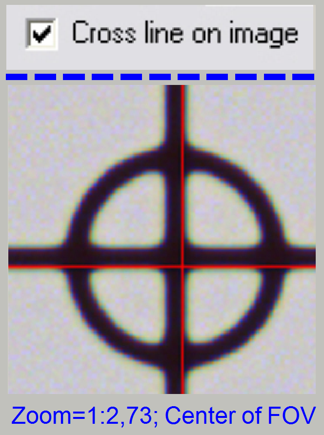
In the tab 'Service' select 'Microscope
control' and check the option 'Cross line on image'. In the part of the
X-Y-control select a step size of two steps and go upward, until the tissue
moves.
Now go in opposite direction
and count the clicks until the tissue moves. If more then 3 clicks are
required, the hysteresis is too much.
See also: 'Stitching' and 'Exchange the Y-drive
unit'
The following adjustments are done only, if the motor has to be
exchanged, the X-Y-carriage drive unit was removed.
The resolution of the stepper motor by 3200 steps/revolution and the
construction of the spindle together with the transport nut allow a resolution
of 1μm longitudinal movement per motor step; the transport nut eliminates
the slippage if the rotation direction changes.
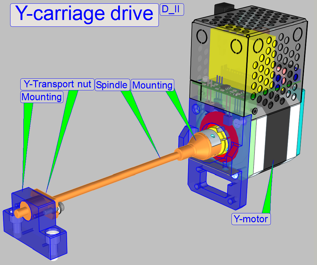
The only difference between the Y-carriage drive unit and the X-
carriage drive unit is the length of the transport spindle; the spindle of the
X-unit is shorter.
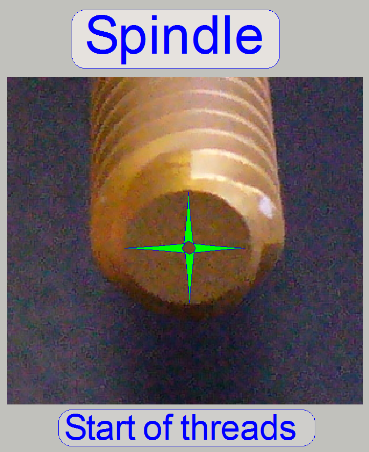
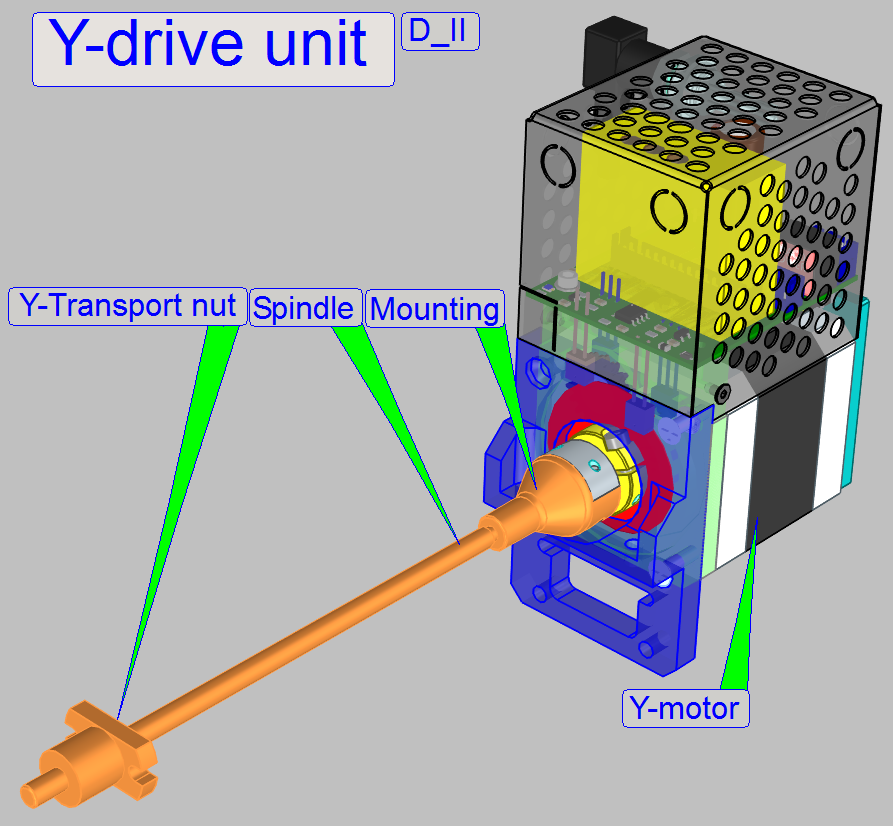
Transport
spindle; Multi (4) thread spindle
The spindle (together with the transport nut) is used to transform
rotation into slippage free longitudinal movements. The four threads on the
spindle guarantee a precise movement, increase the torque of the mechanical
drive and help to reduce or eliminate slippage and hysteresis.
The spindle is mounted to the rotor axle by a pressure connection
solution.
·
Set the appropriate motor to Home1,2.
·
Move the rotor by about +16000steps (5 revolutions).
·
Loosen the spindle mounting bolts and move the spindle
mounting from the rotor shaft.
·
Set the appropriate motor to Home1,2.
·
Move the rotor by about +16000steps (5 revolutions).
·
Move the spindle mounting onto the rotor shaft and
tighten the bolts.
·
Check the hardware
limits for the carriage.
·
By loosening the spindle mounting and rotating the
motor shaft with the service program, the movement range of the carriage can be
adjusted.
1.
Loosen the spindle mounting bolts.
2.
Rotate the motor's rotor some revolutions or some
100steps forward or backward as desired and tighten the mounting bolts.
3.
Check the hardware limits.
·
Repeat the procedure until the requirements of the
hardware limits are fulfilled.
See also: Limiters and define
hardware limits
The transport nut moves the Y-carriage (or any other, connected peripheral)
to the desired position; the thread of the spindle and the nut moves the
peripheral by 3.2mm if the rotor (and the spindle) have done one revolution.
To reach the appropriate limits of the mechanical drive, the rotation of
the spindle in relation to the Home1,2 position of the rotor can be adjusted
with the spindle mounting.
The limits have to be less then 1600 steps in negative direction counted
from Home1,2 and less then 1600 steps after 23revolutions of the spindle (if
Y-carriage); see also 'The hardware
limits' and 'Find the
hardware limits for the Y-carriage.
Watch video: Y-Drive unit; D II
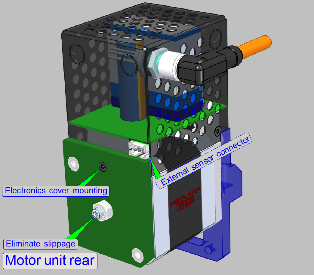
Rotor slippage is defined as the longitudinal movement of the rotor axle
in its bearing. If the rotor direction has changed this slippage may increase the
longitudinal position fault drastically, even if we try to reach a longitudinal
movement resolution of 1µm /rotor step. To eliminate this slippage, the
adjustment bolt with counter nut 'Eliminate slippage' can be used.
Important
This adjustment is already done during the component implementing
procedure; please do not drive the bolt or the nut!
Dismount the carriage drive unit
·
Set the appropriate motor to Home1,2.
·
 Move the rotor by about
+16000steps (5 revolutions).
Move the rotor by about
+16000steps (5 revolutions).
·
Remove the mounting bolts of the appropriate transport nut and pull it out of
its holder.
·
Remove the motor
mounting bolts from the rear.
·
Remove the motor
mounting bolts from top.
Pull the motor together with the entire carriage drive unit away from
the carriage.
- Set the motor to Home1,2.
- Move the
rotor by about +16000steps (5 revolutions).
- Fit the transport nut module into its
mounting.
- Fit the motor mounting to its carriage and
drive in the bolts from top, the unit should be even a bit moveable.
- Drive in the bolts from rear of the motor,
the unit should be even a bit moveable
- Drive in the bolts of the transport nut
module.
- Set the motor to Home1,2.
- Check the optimal movement of the carriage
from limiter to limiter with the service program, it should move smoothly,
evenly and noiseless.
- Tighten the motor mounting bolts and the
transport nut mounting bolts correctly.
- Check and /or adjust the hardware limits.
Watch video: D_II_Dismount_Y-Drive
unit