Focus unit; D_II
For technicians
and partly for sales managers!
Enhancements
 Construction of DESK_II's
focus unit has changed in relation to the focus unit of DESK; since summer 2016
main modifications are:
Construction of DESK_II's
focus unit has changed in relation to the focus unit of DESK; since summer 2016
main modifications are:
Shutter mechanics removed
Because the
scanner unit of the DESK is never able to scan slides in FL scan mode, the
mechanical shutter is also not required.
In DESK, the
shutter unit was implemented for the Hardware limits and to keep compatibility
with SCAN and
Hardware limits not required
Because the
shutter wire is removed, the rotation of the ex-center is no longer limited.
The ex-center may rotate unlimited
Ex-center position visualization pin
In the position
of the shutter arm of the ex-center, now only a visualization pin is
implemented to make the ex-center position adjustment possible.
Stepper motor type exchanged
In the DESK,
there was a 2-phase stepper motor with 200 full-steps/revolution used, so a
resolution of the 3200µ-steps /revolution is possible.
In the DESK_II a
5-phase stepper motor is implemented, this guarantees a higher full-step
resolution, and more smooth movement of
the rotor and so, vibration and noise are also reduced.
One revolution of
the of the stepper motor is now 6400µ-steps/revolution.
Increased slide thickness
The modified
focusing solution allows now focusing of slides with a thickness of 0.95mm to
1.20mm.
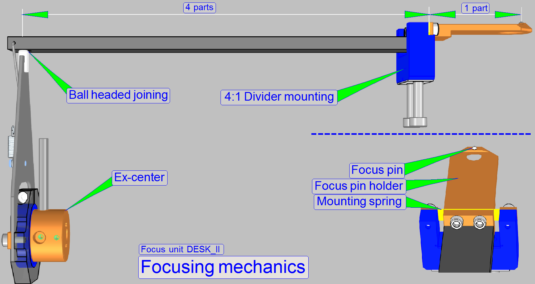
Modified focusing mechanics
To focusing
slides with a thickness of 1.20mm, the movement range of the focus pin had to
be increased.
To reach this,
the relation of the divider was modified and the stepper motor's step angle was
decreased.
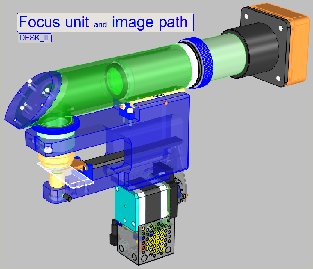
Functional overview of
the focus unit
Physically, the focus position is defined by the
distance of the objective to the tissue. If the tissue is in the focus of the objective,
a sharp image is seen by the camera. Because the tissues are different in
thickness to each other, and the thickness can change inside the same tissue
also, the focus position must be checked and corrected always, during the scan
procedure.
- In Pannoramic DESK type scanners the real
focus position is found by moving the slide toward or away from the
objective via the focus pin.
- The focus position is influenced by both, the fixed (adjustable)
objective position and the actual position of the focus pin.
Furthermore, if the slide will be exchanged, the
specimen holder must be moved away from the objective to avoid collision.
During slide actions, except focusing, the objective
must be protected against touching the cover slip and the focus pin and the 4:1
divider must be protected against overstraining. This is realized by the focus
unit, with the different positions of the focus pin and the positions of the
specimen holder, controlled via the X-Y-stage unit.
- Components and construction of the focus unit is mainly defined by
the requirements of the objective.
The default objective magnification in the DESK
scanners is 20x, but the user can order the 40x
magnification also, explicitly.
The focus unit is able to hold 2 objective types.
 20x magnification and
 - 40x magnification
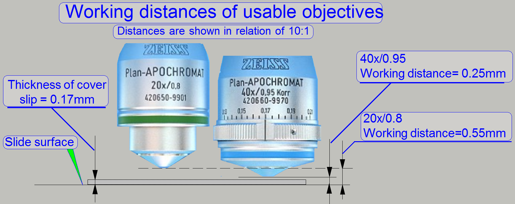
The worst case is defined by the parameters of the 40x objective.
As you can see, the gaps between cover slip
and objective are very small, especially if the objective Plan-APOCHROMAT
40x/0.95 is used.
- The objective exchange is realized manually, so an adjustment of
the objective position is required after exchange.
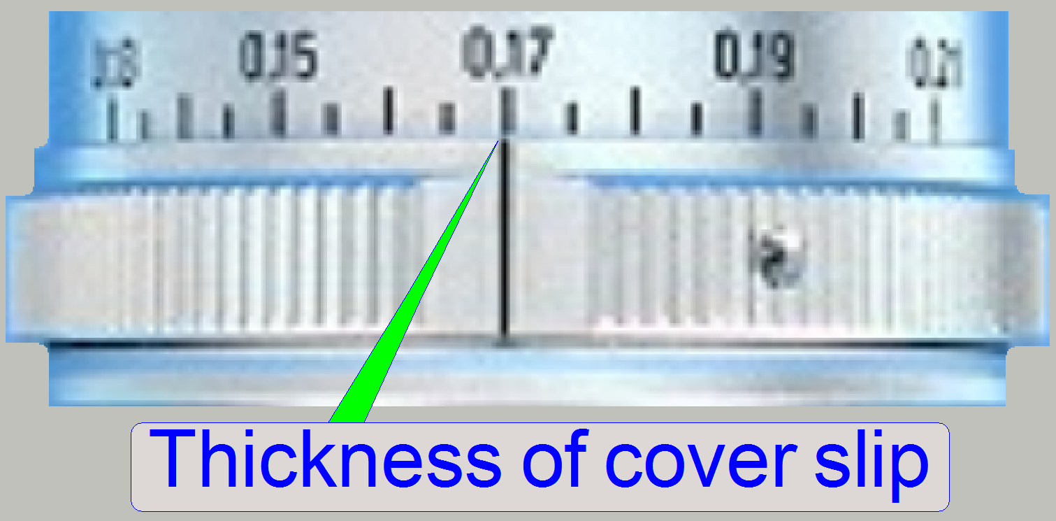
On the scale of the 40x objective, the nominal
thickness of the cover slip should be selected.
- If the real thickness of the cover slip differs from the selected
value, the quality of the scanned FOV may be reduced!
General
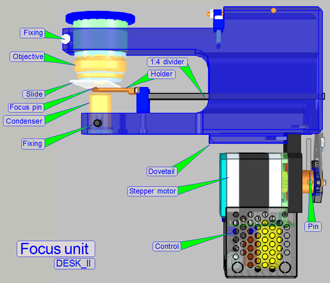
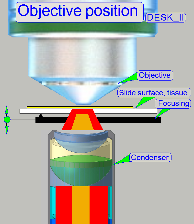
The described focus unit is a component of the Pannoramic DESK_II scanner and contains the following main parts:
· The focusing part (driven by the focus stepper motor)
· The objective with mounting
nut and objective position fixing.
· The condenser with its
position fixing.
· The focusing mechanics
(Ex-center, 4:1 divider, Focus pin).
· Dovetail unit mounting, so the correct
mounting position is found again after the unit was removed and inserted again.
· To adjust the ex-center position, a
visualization pin (here named as "Pin") is implemented
The focus unit gives the possibility of focusing the FOV (field of
view, seen by the scan camera) automatically during the scan process of the
sample.
The unit was developed for the use of objectives of the
following types:
Plan-APOCHROMAT
20x/0.8 and Plan-APOCHROMAT
40x/0.95
The objective type “Plan-Apochromat” contains several, special chromatically and
spherically corrections and delivers so an image of very high color trueness
with very small spherically and chromatically aberration.
If the mechanical dimensions do not exceed the size
of the Plan-APOCHROMAT 40x0.95 type objective, the mechanical mounting is
identical and the focus distance of the objective to the tissue is not closer
than 0.25mm, other kind of objectives can be used also but it is strongly not
recommended!
· Always check with 3DHISTECH first when a
different objective should be used!
The exchange of the focus unit is possible
- If the stepper motor
or its electronics for the focus unit is faulty
- If the
shape of any part is deformed or a part is broken.
- If the
focus unit has any fault and you are
unable to fix it.
Requirements
- Service program for Pannoramic scanners (SlideScannerService.exe)
with actual license file
- Pannoramic
Scan Software (version 1.21. or higher) and Pannoramic
Viewer software (SlideScanner.exe, SlideViewer.exe) with dongle or actual
license files
- 1.5,
2.5, 3 and
- Hardware
and construction knowledge of Pannoramic type scanners
Attention: Do
not mix the versions of SlideScanner.exe and SlideScannerService.exe! Always
use these programs with the same version number. Otherwise the
SlideScannerService.exe program could produce unwanted results and
SlideScanner.exe does not work correctly or even freeze!
In Pannoramic type scanners
the objective is mounted so, that the focus point of the objective is in the
middle of the focus range, offered by the movement range of the focus pin
during focusing.
- It is very important, that the objective position is adjusted well;
otherwise, if the objective's focus point does not match the focus range,
offered by the focus pin movement range, a focused camera image can never
be produced!
- Because the slide thickness can vary from 0.95 to
![]() “Adjust the
objective position”.
“Adjust the
objective position”.
The slide is hold in the specimen holder (not shown;
see the X-Y-Stage). To achieve a perpendicular movement of the slide in
relation to the objective, the specimen holding mechanics contains a
parallelogram. This guarantees the position of the tissue to be always
perpendicular to the optical axis during focusing. The specimen holder has a
mechanical preload, so the slide has always a connection to the focus pin.
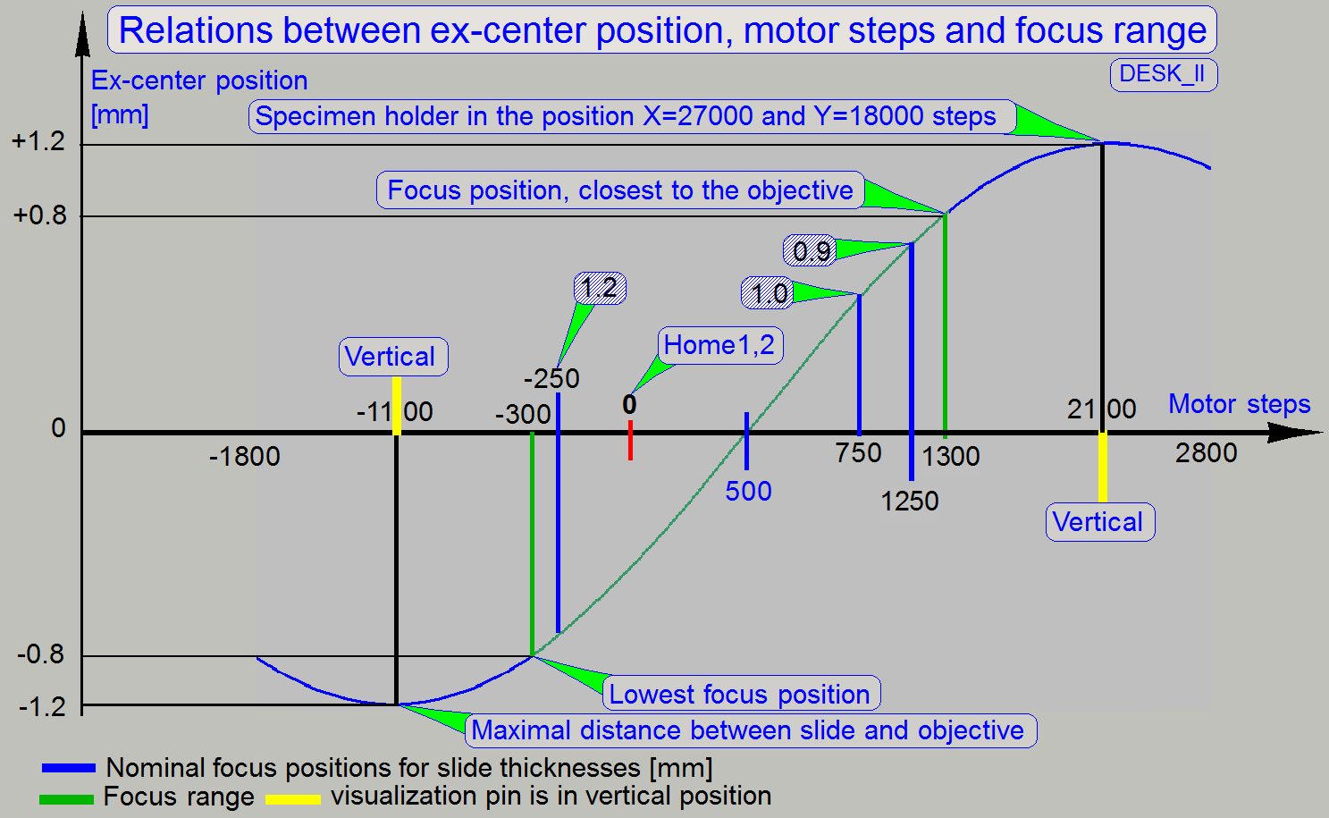
To avoid collision of the objective with the slide
during crossing the upper peak of the sine wave, the X-Y-stage is moved to a
place (X=27000 and Y=18000 steps) where the focus pin is not in connection with
the slide or the specimen holder; otherwise the 40x objective would collide
with the slide or specimen holder.
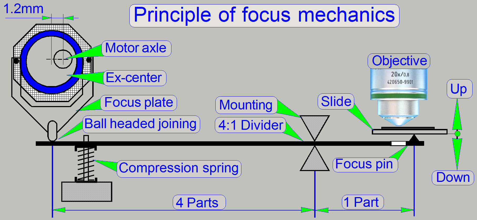
The focus pin is moved by a stepper motor via an
ex-center and a 4:1 divider. The resolution of the stepper motor with
6400µ-steps /revolution, the characteristics of the ex-center and the 4:1
divider allows a very fine resolution of the focus steps and so tissue
focusing.
Remark
The connection of the ball headed joining is realized
with the connection spring and the triangle (see ex-center) and not by a
compression spring as shown.
The focus position of the FOV is found, if the camera
sees a sharp image. To reach this, the scan camera takes images in different
positions of the entire focus range and the software finds the best focus
interval. When this interval is found the real focus position is found by
iteration of the interval.
In opposite to the DESK,
The Home position of the entire mechanics is situated
inside the focus range. The option Home1,2 will never be executed during normal
scan operations and is used during system integration only or before the ex-center fixing bolt will be tightened
(if mechanical adjustments are done on the ex-center). In this case, the
mounting of the ex-center starts after a Home1,2 execution. This solution is
important for protecting the 40x objective.
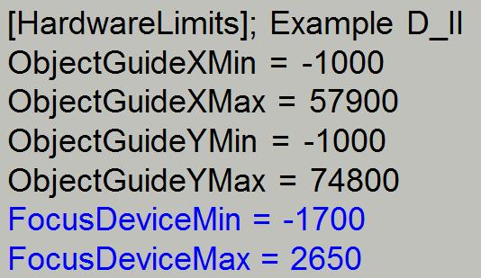 Hardware limits
It is true,
that the hardware limiters are removed from the focus unit, but to set limits
for the software, the limits in the ini-file are set
to -1700µ-steps and to 2650µ-steps respectively.

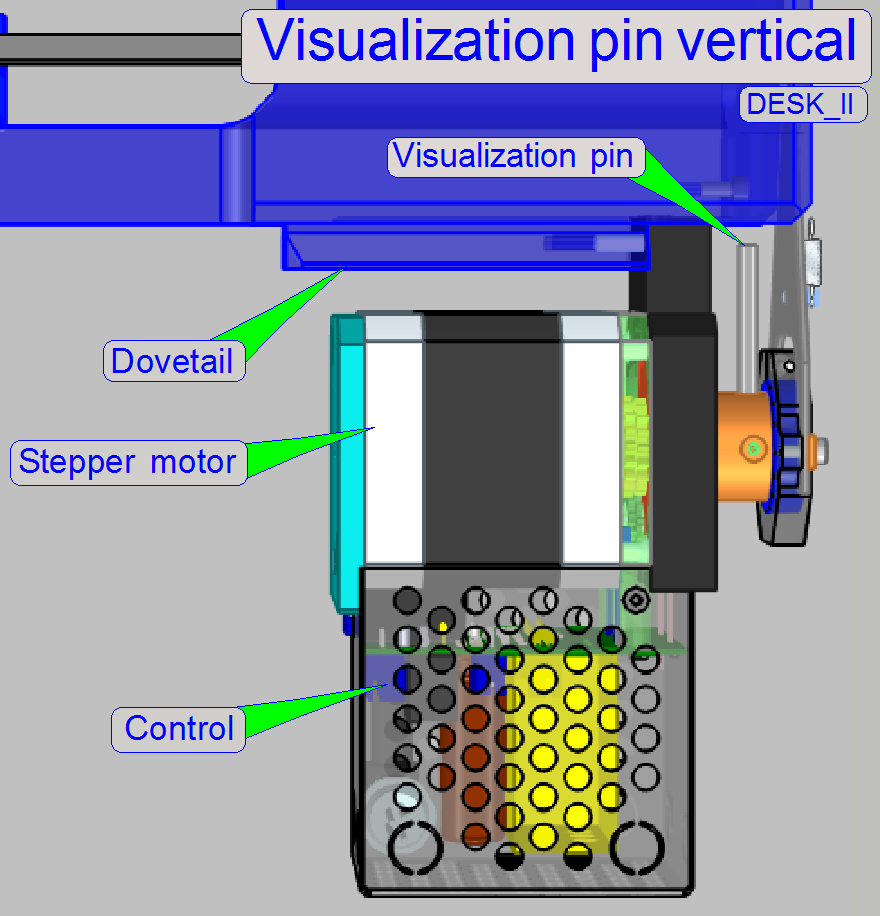 Visualization pin in vertical position
This is a special position for adjusting the physical
ex-center position on the motor axle. This adjustment defines the focus range;
the sine wave crosses the X-axis at 500 motor steps (see above).
- Use the position of the slot in the focus plate mounting to adjust
the visualization pin vertical, while the rotor stays in the position
-1100steps.
In earlier developed scanner systems (DESK,
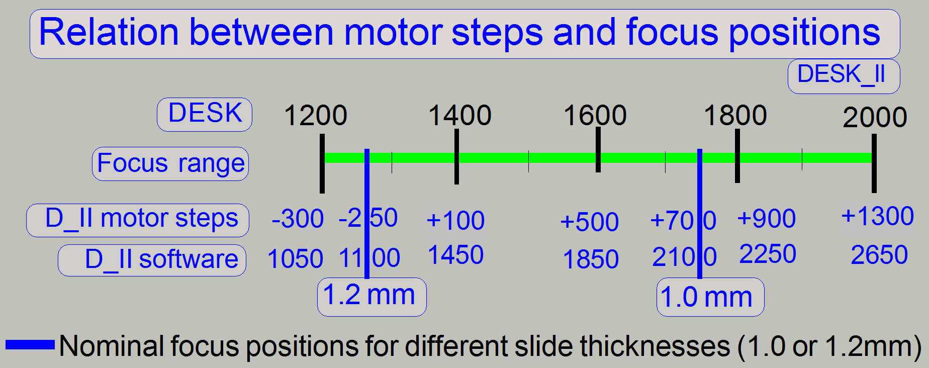
Because the resolution of the motor is increased by
twice (1 revolution of the motor axle is done in 6400 steps), the focus range
is now 1600 steps, in the D_II.
Because the focus range is physically counted from -300
steps to +1300 steps, and negative numbers as focus position are unusual, the
entire focus range is shifted in the software to the focus range from 1050 to
2650; add to the physical step number 1350.
In the Pannoramic DESK_II: SW
focus position = HW stepper motor position + 1350.
Because the specimen holder of the scanner
DESK_II can hold slides with a thickness of
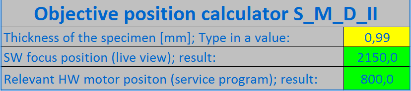
- Measure the thickness of the slide with tissue to be used (but
without the cover slip); use the caliper.
- Use the “Objective
position calculator”, shown on the right to find the nominal focus
position.
- Insert the measured slide into the specimen holder and set the
appropriate (calculated) focus position in the live view of the program
SlideScanner.exe
- Adjust the objective position to the preset focus position until a
focused image can be seen in the live view.
![]() “Check / adjust
the objective position”
“Check / adjust
the objective position”
Components and mechanical construction
All stepper motor relevant information, like step
number and direction; go to Home1,2 and the state of the sensors Home1 and
Home2 are transferred via the stepper motor cable; this is connected to the USB
controller unit.
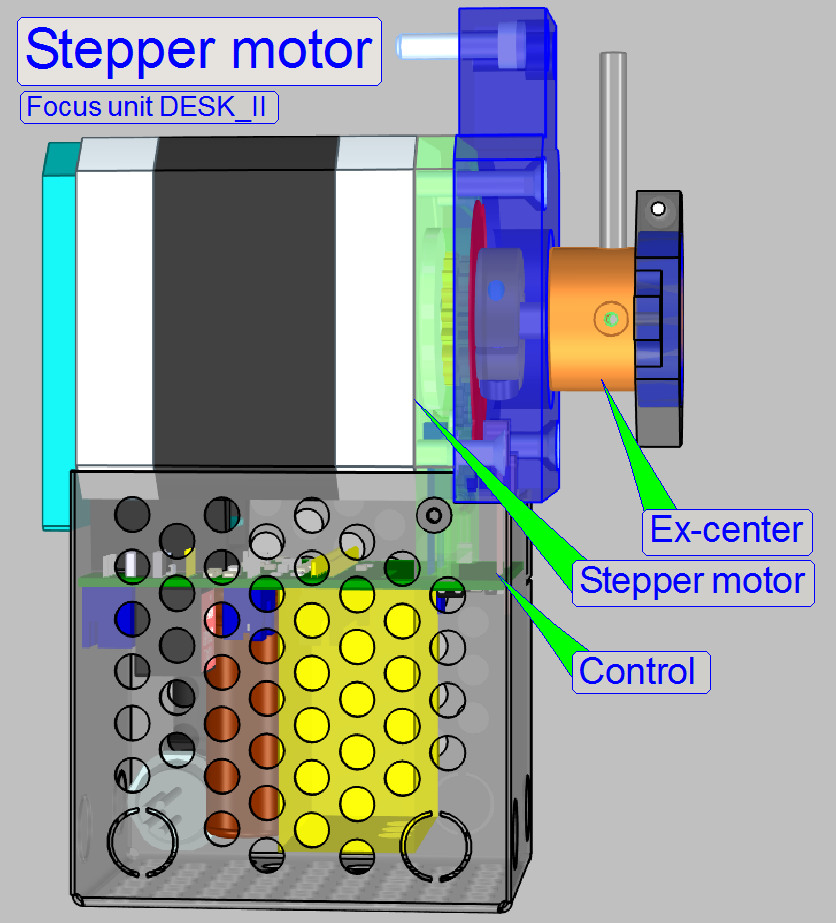
In opposite to the DESK,
On the ex-center mounting the shutter arm is removed,
only a visualization pin is situated for the shutter position adjustment; now
the focus motor can not do a full revolution in any direction.
Watch video: Stepper motor
Attention
A
small gap between motor mounting surface and ex-center mounting should exist,
otherwise, if the ex-center mounting rubs on the motor mounting surface, the
focus unit may lost rotor steps and so the scanned tissue may be out of focus
or blurry, even if the focus rotor direction had changed.
Adjust ex-center position
1.
Go to
the positions Home1,2.
2.
Go
forward to the focus motor position +500 steps.
3.
In this
position the visualization pin should showing exactly up. A deviation of
approx. 10 steps from the vertical direction is maximal allowed.
4.
If
not, loosen the excenter mou
nting bolt, and rotate the visualization pin exactly
upward and tighten the mounting bolt.
5.
Check
the correct position with the service program.
6.
If
the deviation is too much, repeat the adjustment from step 1.
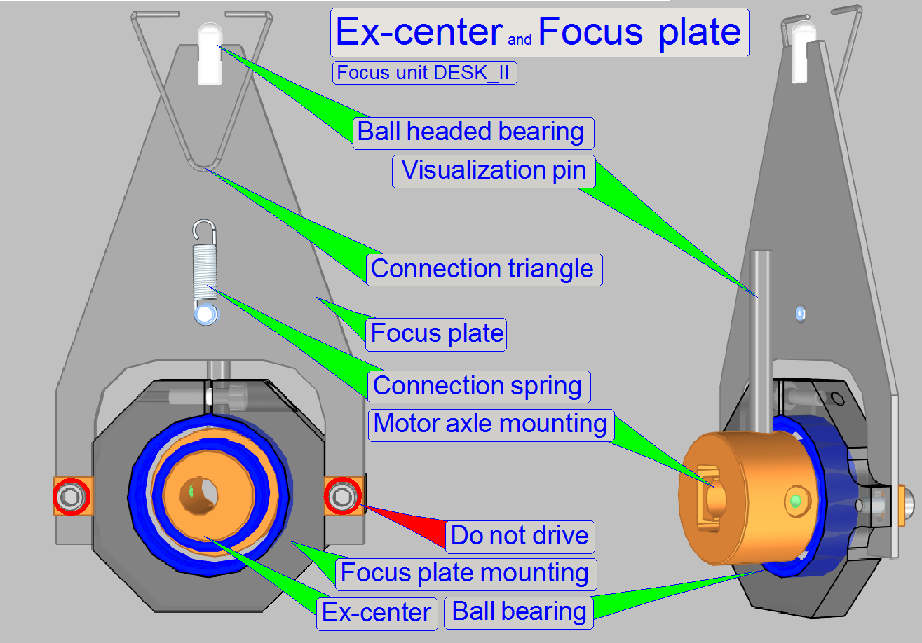
The motor axle of the stepper motor rotates the
ex-center on which the focus plate is mounted and this moves the 4:1 divider.
Attention
The mountings of the focus plate should not be
loosened; here the position of the focus plate and so the position of the 4:1
divider and the position of the focus pin is adjusted!
Because the movement of the focus pin is very small,
the adjustment of the focus pin position is delicate; the focus plate mounting bolts position must not be altered.
· The adjustment of the focus pin position can be done only
with special tools!
Watch video: Ex-center and focus
plate
The connection between focus plate and divider is
realized with a ball-headed joining because the ex-center does an up-down and
additionally a left-right movement.
The connection spring ensures a slippage-free
connection between focus plate and 4:1 divider.
The connection spring ensures a slippage free connection of the ball
headed joining.
The bearing of the 4:1 divider and the ball-headed
pin of the focus plate eliminates the unwanted left or right movement.
On the other end of the 4:1 divider the focus pin is
realized. The focusing of the tissue is done by moving the focus pin toward or
away from the objective; the mechanical construction allows a focus pin
movement of
Watch video: Focus mechanics
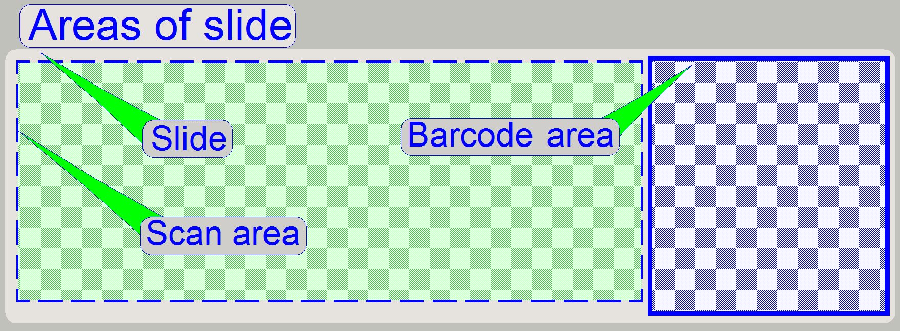
The scan area defines the part of the slide on which the
tissue, scanned by the scan camera, is expected to be. The entire scan area is
captured by the preview camera in three sections and is shown in the preview
area of the program SlideScanner.exe.
The scan area is limited by the mechanical construction of
the specimen holder and should be defined as large as possible; it is not
defined in relation to the cover slip.
In all cases, the specimen holder should never be touched by
the focus pin or the objective! In other words, the scan area is that area of
the slide, on which the focus pin and the objective (especially 40x
magnification) can be moved seemingly during scanning the tissues, without
touching the specimen holder.
As mentioned before, the focus unit may be equipped with a
20x or a 40x objective. Because the focus position of the 40x objective is very
close to the tissue, the scan area, defined for the 20x objective is no longer
valid, to avoid collision of the objective with the specimen holder.
If the objective will be changed from a 20x to a 40x
magnification, the scan area must be defined again and therefore the preview
calibration must be executed again also. During defining the scan area for the
40x objective, the position of the focus pin and the position of the objective pupil should be checked to avoid
touching of the specimen holder! Adjust the limits in the nominal focus
position!
If the objective is changed from the 40x to a 20x
magnification it is not bound to define the scan area again, if the smaller area can be
accepted. In all cases, if the scan area
was modified, a preview calibration is bound to do.
![]() “Working
distances” and
“How to exchange the objective in DESK”
“Working
distances” and
“How to exchange the objective in DESK”
Watch video: Exchange objective
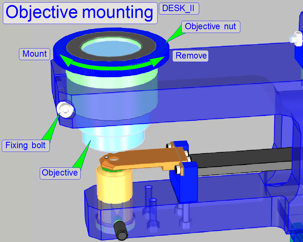
- Remove
cables from the camera as required.
- Loosen
the mirror tube mounting bolt.
- Remove
the mirror tube rearward.
- Loosen
the fixing bolt of the objective mounting.
- Remove
the objective nut with objective.
- Exchange
the objective.
- Insert
the objective nut with objective until to the focus position.
- Tighten
the fixing bolt of the objective mounting.
- Mount
the mirror tube; move it frontward until is stops.
- Tighten
the mirror tube mounting bolt.
- Reconnect
removed cables.
- Adjust
the focus position.
- Define
scan area
- Execute
preview calibration.
Hint
If the exchange of the objective is often done, the
technician may create two ini files, one for the
parameter values with the 20x objective and one for the values with the 40x
objective.
By easily exchanging of the ini
file content, many limit definitions may be left out.
The focus position adjustment of the objective is bound to
do always!
Important
Please make a security backup of the ini
file before modifying values!
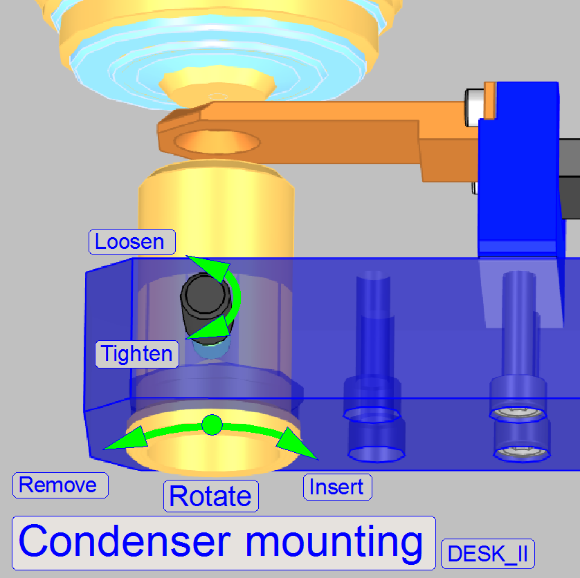
- Remove
the focus unit (optional).
- To remove the condenser, loosen its fixing and drive the condenser
out; away from the objective.
·
To
mount the condenser, put it into its holder and drive the condenser in; toward
the objective.
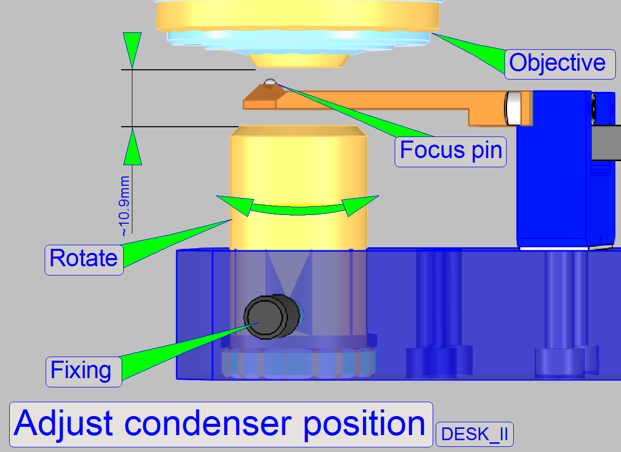
The adjustment of the condenser is important for the bright,
uniform and optimal illumination of the FOV. This reduces so the exposure time
of the camera and increases the quality of the scanned tissue.
The position of
the condenser affects the following:
- The size of the
visible FOV (color shading)
- The image
contrast
- The image
resolution (the numerical aperture) and
- The exposure time.
- We assume that the focus unit and the is
already adjusted; the position of the objective is correct.
- Use the program SlideScanner.exe and insert a
slide with cover slip, create a live view and click inside the tissue.
- Use the tool “Auto focus”.
- If the tissue is in focus, find a “clean” FOV (without tissue or
dust). Use the positioning tool
 and click outside the tissue but inside
the cover slip of the preview window in the program “SlideScanner.exe”.
and click outside the tissue but inside
the cover slip of the preview window in the program “SlideScanner.exe”.
- Loosen the condenser’s fixing bolt.
·
If
you can not see the hole of the condenser position adjustment tool, calculate
the exposure time and move the adjustment tool on the optical axis until the
image of the drilling or a part of it can be seen in the live view.
- Rotate the condenser toward to the objective, so the start position for
the adjustment will be found; the brightness will increase.
- Rotate the condenser backward and look at the live view. Beware of
the condenser cover (shutter), don’t close it and don’t bend it. You will
see, that the drilling of the condenser position adjustment tool comes
into focus. While rotating the condenser you can also observe that the
brightness decreases.
 If the center drilling of the
adjustment tool is in focus, the condenser position is nearly found, a
small correction of the condenser position have to be done, because the
focus position of the drilling is not the real position of the collimator
lens. Drive the condenser by about ¼ revolution more backward and
stop the move of the condenser; tighten its fixing bolt.
If the center drilling of the
adjustment tool is in focus, the condenser position is nearly found, a
small correction of the condenser position have to be done, because the
focus position of the drilling is not the real position of the collimator
lens. Drive the condenser by about ¼ revolution more backward and
stop the move of the condenser; tighten its fixing bolt.
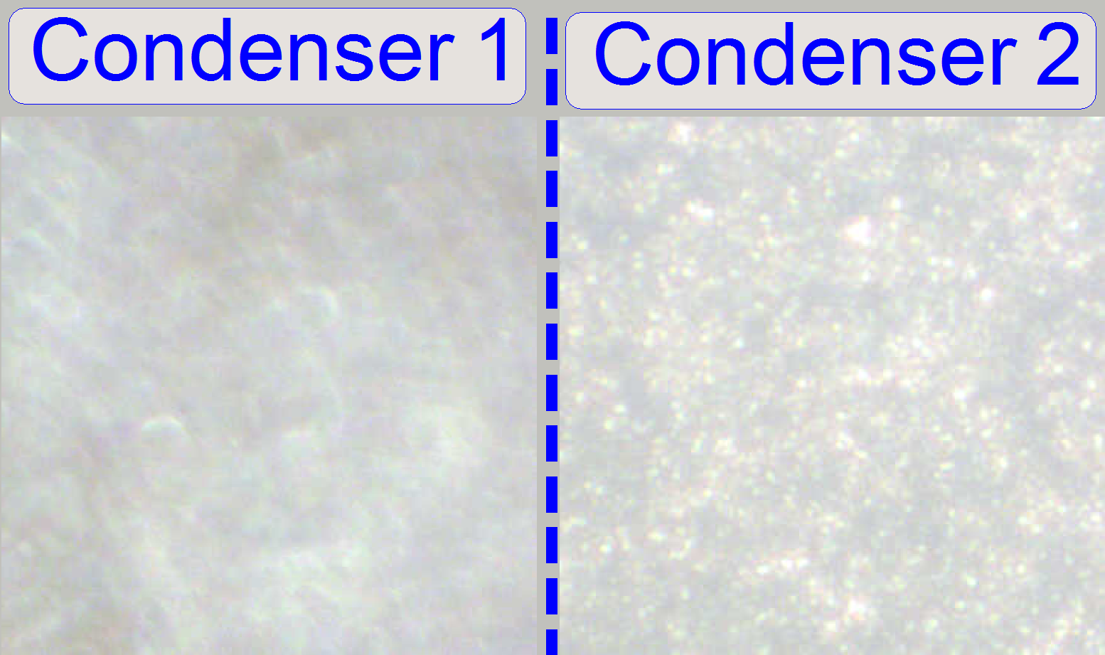
- Check the correctness of the adjustment in the live view and by
scanning a tissue or a part of it.
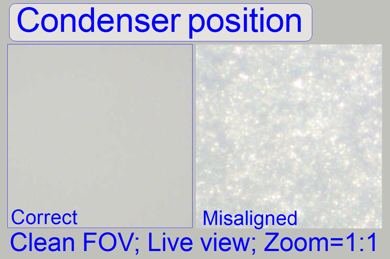
- If the “clean FOV” is evenly
illuminated the condenser position is correct.
Dismount; mount the focus unit
The mounting of the focus unit with objective changer
and the mounting of the X-Y-stage is realized with dovetails; these are hold by
dovetail fixing clamps.
- Rotate the screw driver clockwise to open (loosen) the dovetail
clamp.
- Make sure, that the X-Y-Stage is not
in the X-home position, because in this position the focus unit can not be
removed.
1. With the service program go forward to the
position 10,000 steps in +X direction (3 full turns of the motor axle).
2. Disconnect the bus cables DOJ-1 of the
objective changer and FCJ-1 of the turret stepper motor.
3. Disconnect the cables of the focus motor
(optional).
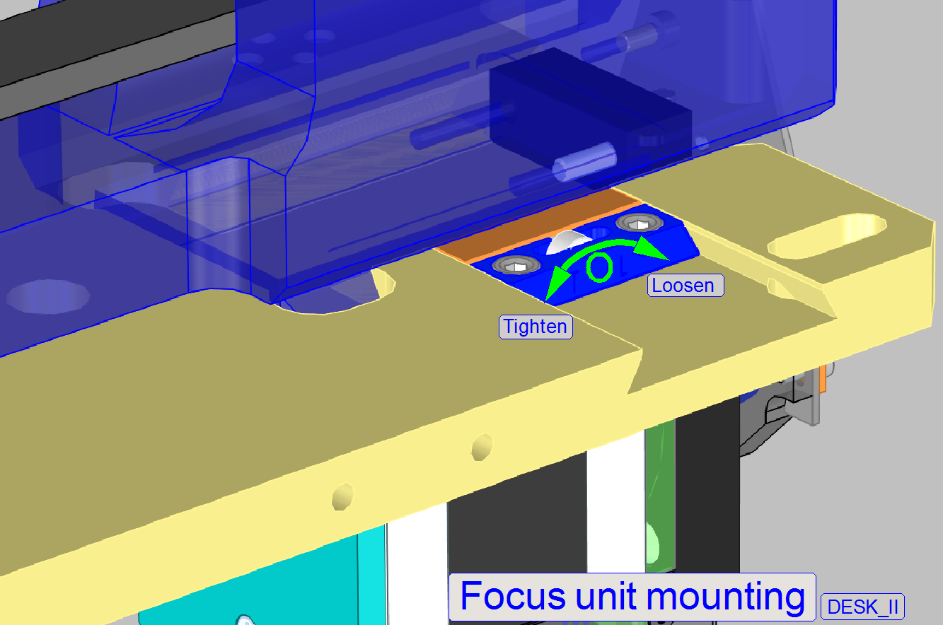
4. Loosen the fixing bolt of the focus unit
mounting; turn the screw driver clockwise!
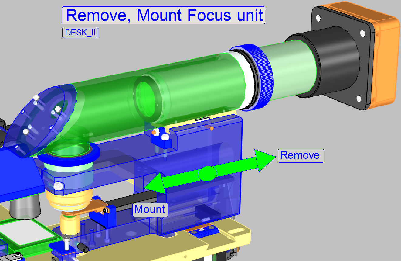
5. Remove the entire focus and objective
changer unit by pulling the unit backward.
Watch
Video: Remove mount
focus unit (D_II)
6. Insert the focus unit with objective changer
into the dove tail of the scanner plate until the physical limit is reached;
take care on the objectives.
7. Tighten the fixing bolt of the focus unit
mounting; turn the screw driver counter clockwise!
8.
Connect
the bus cables DOJ-1 of the objective changer and FCJ-1 of the turret stepper
motor.
9. Connect the cables of the focus motor.
Watch Video: Remove mount
focus unit (D_II)
Setup and define the implemented objectives
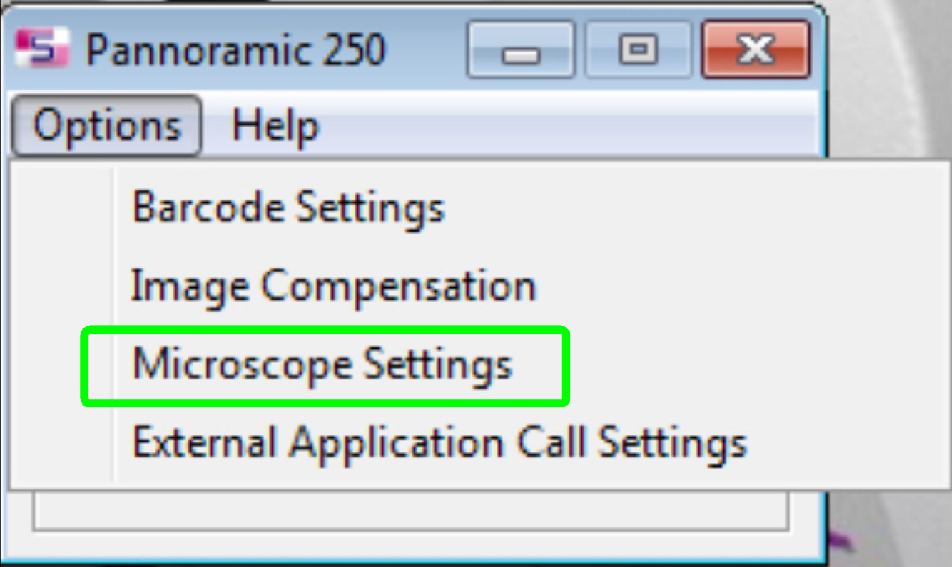 If the objective(s) are implemented and
the program “SlideScanner.exe” finished the start up procedure, select the
option “Microscope Settings” in the menu “Options”.
If the objective(s) are implemented and
the program “SlideScanner.exe” finished the start up procedure, select the
option “Microscope Settings” in the menu “Options”.
- The setup of the objective(s) is done mostly together with the
install of the present cameras.
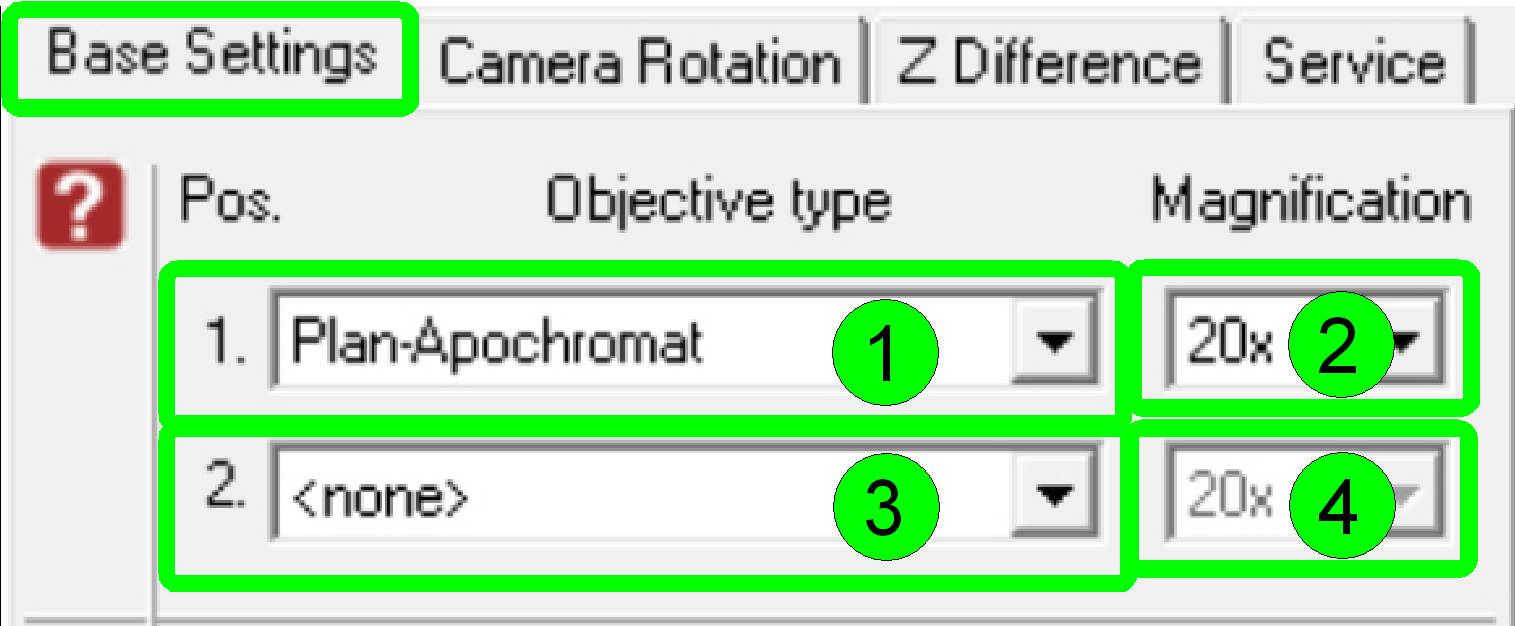 In the dialogue “Base Settings” the
implemented objectives are selected and parameterized.
In the dialogue “Base Settings” the
implemented objectives are selected and parameterized.
By
default and in the scanner D_II
- Select the type “Plan-Apochromat” (1) and
the magnification of 20x (2) in the objective position 1
- Select the type “Plan-Apochromat” (3) and
the magnification of 40x (4) in the objective position 2.
§
If
there is only a 20x objective implemented into the scanner, select
“<none>” (3) in the objective position 2.
Remark
Of course, the dialogue accepts any kind of
magnification in any objective position, but in the Pannoramic
250 the 20x objective should be always in the objective position 1 because this
is the default objective and some adjustment procedures (e.g. the preview calibration
process) uses the 20x objective in the objective position 1!