Adjust the parallelogram
For experienced technicians!
This chapter describes the
adjustment procedure to reach perpendicularity between the objective (optical
axis) and the slide surface (specimen holder).
Because this adjustment needs
special tools and might be time consuming, it should not be done in the field;
an experienced technician may execute these steps in the service center.
The adjustment is based on the
software version 1.15 and the scanner P250, but the principle and almost all
procedures are the same in the scanners S_M_D.
Contents
Prepare the scanner for the
adjustment
Images of the adjustment
steps
The optical axis of the objective
and the glass slide needs to be perpendicular to avoid tilting and partially
out of focus FOVs on digital slides.
As commonly known, in Pannoramic
scanners, the slide is moved with the focus pin around the nominal focus
position (around the position +500 steps; in S_M_D this position is 1600 steps
nominal) during focusing. To shift the slide in the Z-direction (this means
focusing) and not inclining or tilting the slide during these movements, a
parallelogram is used. The parallelogram is mounted between the Y-carriage and
the specimen holder.
Also important is the position of
the parallelogram in relation to the X-Z-plane and the Y-Z-plane of the slide.
Best scanning results will be
reached if the slide is perpendicular to the optical axis.
· The adjustment, described in this chapter, defines the
position of the parallelogram so, that the inclination of the slide in the
X-Z-plane and the Y-Z-plane will not exceed the allowed limits.
More information can also be found
in the chapters:
·
“Focus unit” and “Scan area”, “Principle of focusing”
·
“X-Y-Stage unit”, “Parallelogram” , “Specimen holder”
·
“Optics
and illumination”, “Stage skew check”
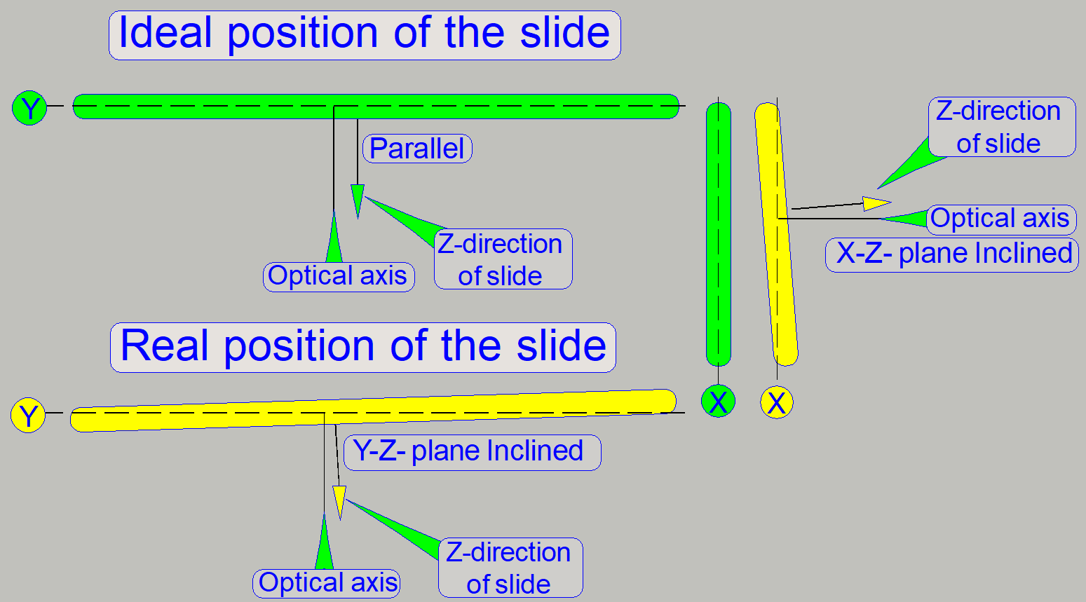
Ideal position of the slide in the specimen holder
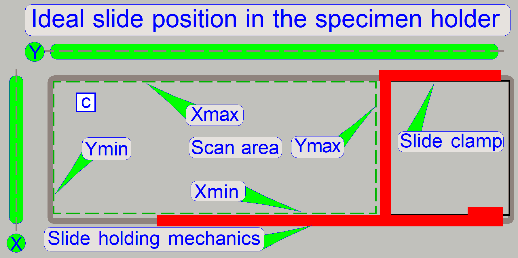
In the ideal position of the slide,
the optical axis is perpendicular to the slide surface and by moving the focus
pin in the range of -300 steps to +1300 steps or by selecting any field of view
inside the scan area, this perpendicularity will not be lost; the LASER beam
(reflected by the slide surface) would be always reflected in the same angle
onto the same position of the screen during movements of the slide.
1)
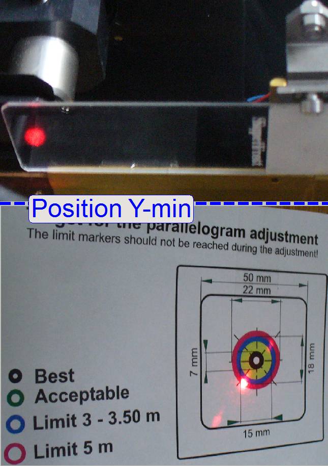
The ideal slide
position would be reached if the field of view (FOV), near to the limit Y-min
would be in the same plane as the field of view near to the position Y-max
(shown with the line (Y))
And
2)
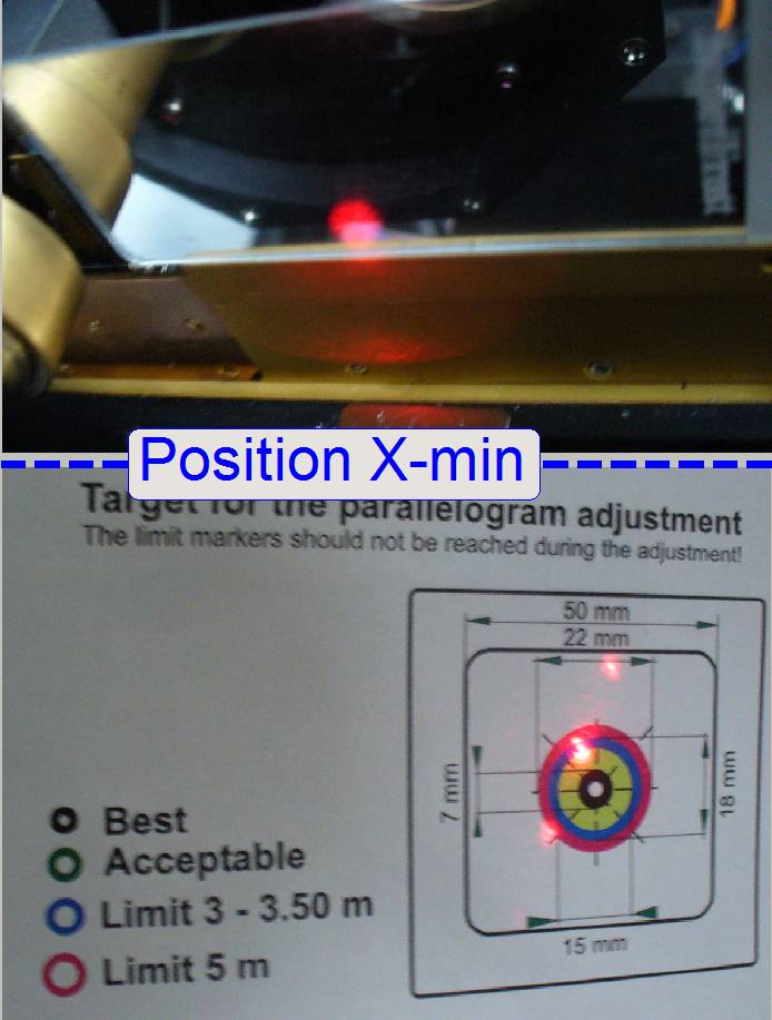
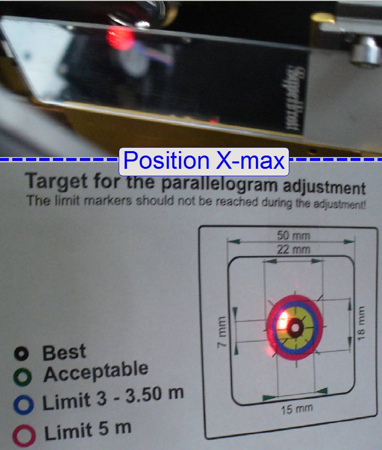
The field of
view, near to the limit X-min would be in the same plane as the field of view
near to the position X-max (shown with the line (X)).
· If this requirement is fulfilled, the optical axis is
perpendicular to the slide surface.
This definition assumes also:
· The slide (the glass) itself is flat, and not tilted
or slant in any direction and the slide thickness does not vary.
· The force of the preload spring of the parallelogram
is not much; otherwise, the pressure of the focus pin against the slide may
tilt the slide surface in positions of the field of view, far away from the
holding mechanics (c).
In practice, the ideal position will
not be reached, but the inclination of the slide in X- and Y-direction may be
reduced as much as possible.
· The slide will be inclined in the X-Z-plane, in the
Y-Z-plane or in both planes at the same time, but always inside the allowed
tolerances.
· In these cases, the Z-axis of the slide will be
inclined, in relation to the optical axis.
The LASER beam will be reflected to
a different position onto the screen (in relation to the ideal position of the
slide).
· The inclination of the slide may result in unfocused
parts of the virtual slide and these are best visible on the border of the
actual field of view in relation to the neighbor FOV, if the inclination of any
plane is too much.
Faulty inclination of the
slide in the specimen holder
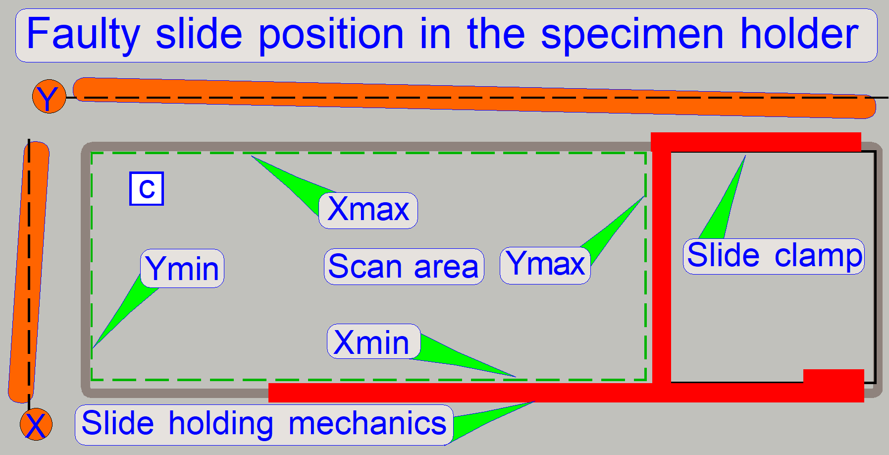
The real position of the slide is faulty if:
· The Z-axis of the slide is inclined, in relation to
the optical axis; outside the allowed limits.
The inclination
angle of the slide’s X-Z- or Y-Z-plane is too much, if the focus of the field
of view differs (the focus difference is visible) on the border to the neighbor
field of view in the virtual tissue and:
· The slide is correctly inserted into the specimen
holder
· The slide is held properly in the specimen holder (the
slide does not change its position during scanning)
· This behavior can be detected often on two neighbor
FOV’s on different positions of the scanned tissue; the border of the FOV is
visible (in relation to the focus).
· The neighboring FOV’s are scanned in the same focus
motor step position
· Some parts of the field of view are out of focus while
other parts of the same field of view are in focus
· This behavior can be found on different tissues
(slides) also.
· By adjusting the parallelogram position, the
inclination of the slide in relation to the optical axis will be minimized or
eliminated; this is the task of the adjustment.
Remark
· During
the tissue creation process the thickness of the sample itself may vary on
small spots and this might also be visible as unfocused part of the virtual
tissue. To decide, whether the thickness of the sample is varying or the
inclination of the slide is the cause of the error, please check always the
focus on the border of the FOV in relation to its neighbor FOV on different
tissues also.
· The
inclination of the specimen (holder) may also be checked in the live view and
with a zoom factor of 2.73 of the scan program; see also: “Stage skew check”.
In all cases
If the scanned tissue shows mistakes
or errors, that may occur in conjunction with non perpendicularity of the
objective (Optical axis) and the specimen holder (slide surface) (some parts of
the field of view are out of focus during other parts of the same field of view
are in focus) and this behavior can be detected very often on two neighbor
FOV’s and there is no difference in focus steps, the following checks have to
be done first:
Please do the following checks before you set up the adjustment tools!
- Check the correct tightness of the X-Y-stage unit; loosen it, check the dovetail mounting for unexpected
behavior (smoothness, dust) move it into the correct position again and
tighten the fixing bolt.
- Check the correct tightness of the focus unit; loosen it, check the dovetail mounting for
unexpected behavior (smoothness, dust) move it into the correct position
again and tighten the fixing bolt.
- Check the correct position and the tightness of the scanner plate; loosen it, move it into the correct position
again and tighten the fixing bolts in the right
sequence.
- Check the correct position and the tightness of the turret unit; loosen it,
move it into the correct position again and tighten the fixing bolts in the right
sequence.
- Insert a slide into the specimen holder and check
the correct fixing of the slide in the specimen holder (the slide should not be inserted slanted!)
- Check the hysteresis in X- and Y-direction.
- Check a well visible part of the tissue in the
“Live view” window as described in the chapter “Stage skew check”.
- Scan the tissue of the well inserted slide and
analyze it for slanted field of views.
Any mechanical reason or
incorrectness named above may result in the incorrectness of the optical axis;
if one component is not placed well in the optical axis, the result is the same
as if the parallelogram would be adjusted wrong!!
When shell I check or adjust the
parallelism between the focus- and the X-Y-stage unit?
To check the parallelism, use always the “Stage skew check” first, before you set up the adjustment
tools!
- If the “Stage
skew check” failed or a faulty inclination of the slide in the specimen
holder was detected.
- If the
parallelogram was removed.
- If the
parallelogram or the specimen holder was exchanged.
- If the entire
X-Y-stage unit was changed.
- If the Focus
unit was exchanged.
- If any spare
part was changed and this spare part is in connection with the parallelism
or the straightness of the optical axis.
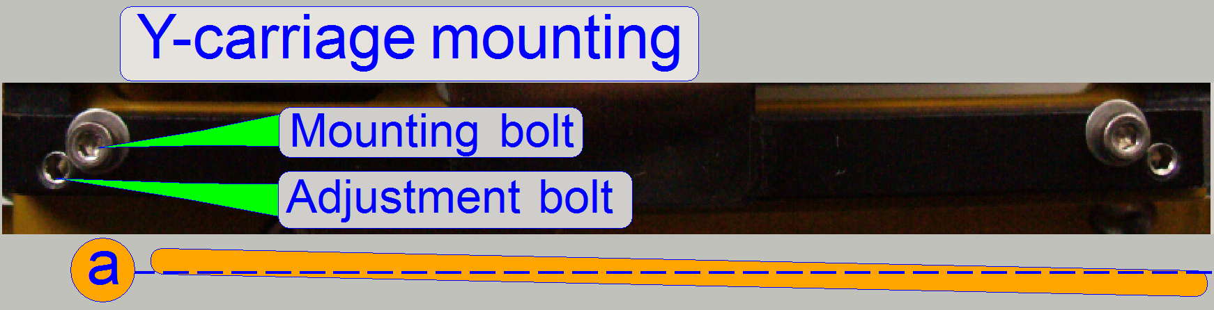
- If the
mounting bolt positions or the adjustment bolts position of the
parallelogram was altered.
Attention
If the parallelogram or the specimen holder is
deformed (bent) or any spring of the parallelogram is broken or deformed, this
adjustment will not deliver the desired results!
Exchange the
appropriate spare part first before doing the adjustment steps.
Important
If any modification on the parallelogram or the
specimen holder mounting was done, please:
· Check or adjust the magazine unit
position.
· Check or adjust the
correct position of the specimen
holder fixing fork.
·
Check or define the scan area again
before scanning tissues!
·
If the scan area was modified, please
execute the preview
calibration also.
·
Check the darkfield preview.
Requirements
· The
tools, described in the chapter “Tools used for the adjustment”.
· Diverse
hexagon key bolt drivers
· Service
program “SlideScannerService.exe”
· Scan
program (SlideScanner.exe)
· Viewer
program (“SlideViewer.exe”)
· Required
time may be 2 hours or more.
Remark
The required time depends highly on the misalignment
of the parallelogram, the post adjustments and checks that has to be done (see
above “Important”) and, nevertheless, the experience of the technician.
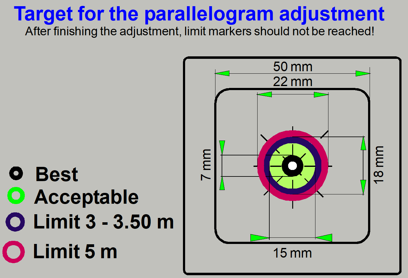
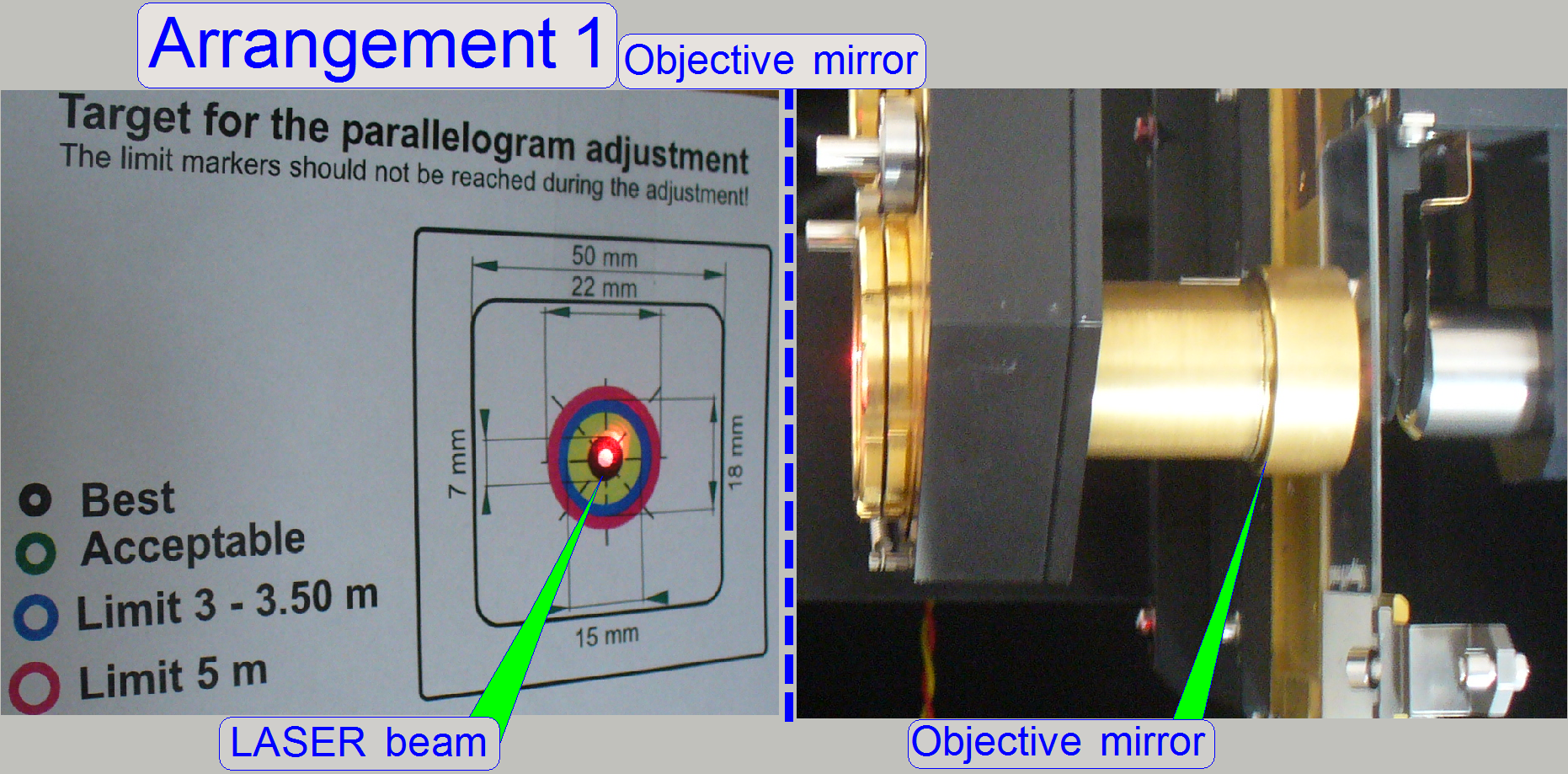
The target is placed in a nominal distance of about 3m
to 3.5m from the scanner onto the wall and is used as a screen.
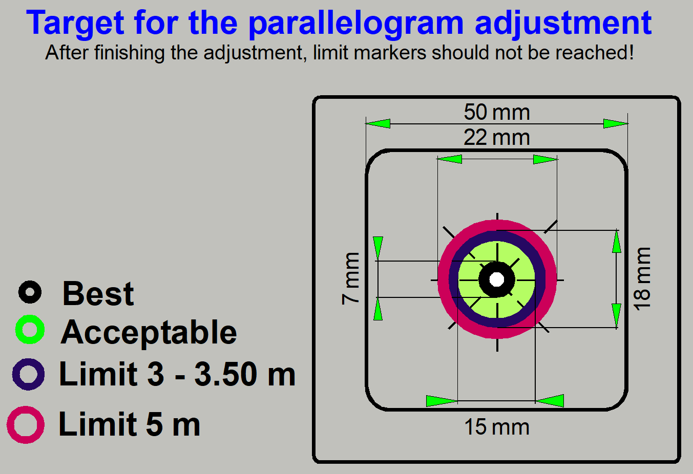 The marker
areas on it are used to check the adjustment result.
The marker
areas on it are used to check the adjustment result.
The momentarily adjustment is qualified nearly in the
center of the scan area and in the focus positions:
-300 steps +500
steps and +1300 steps
If the travel of the LASER beam does not go out of the
green area during the focus movements (if the distance is in the range between
3m - 3.5m), you have shot the bull’s eye.
If the distance is shorter than 3meters (e.g. only
2.5m) the allowed movements should be closer to the black circle in the center;
the acceptable (green) area has to be defined smaller.
For best adjustment results a distance of at least 3m
is recommended; further details will be discussed later.
·
You may also create and print your own
target by the help of any image editor that is
able to draw circles or print the example target.
LASER
source holder with beam mirror
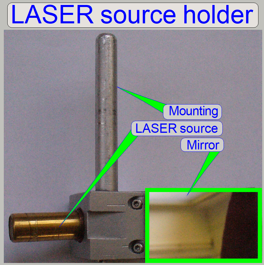
As light source of the LASER beam a LASER pointer or
any other kind of LASER source can be used; the mechanical construction may be
important for the mounting possibilities.
Precautions
Never look directly into
the LASER beam of the LASER source! The emitted LASER beam has only a power of about
0.01watts but this is enough to damage the retina of the eye!
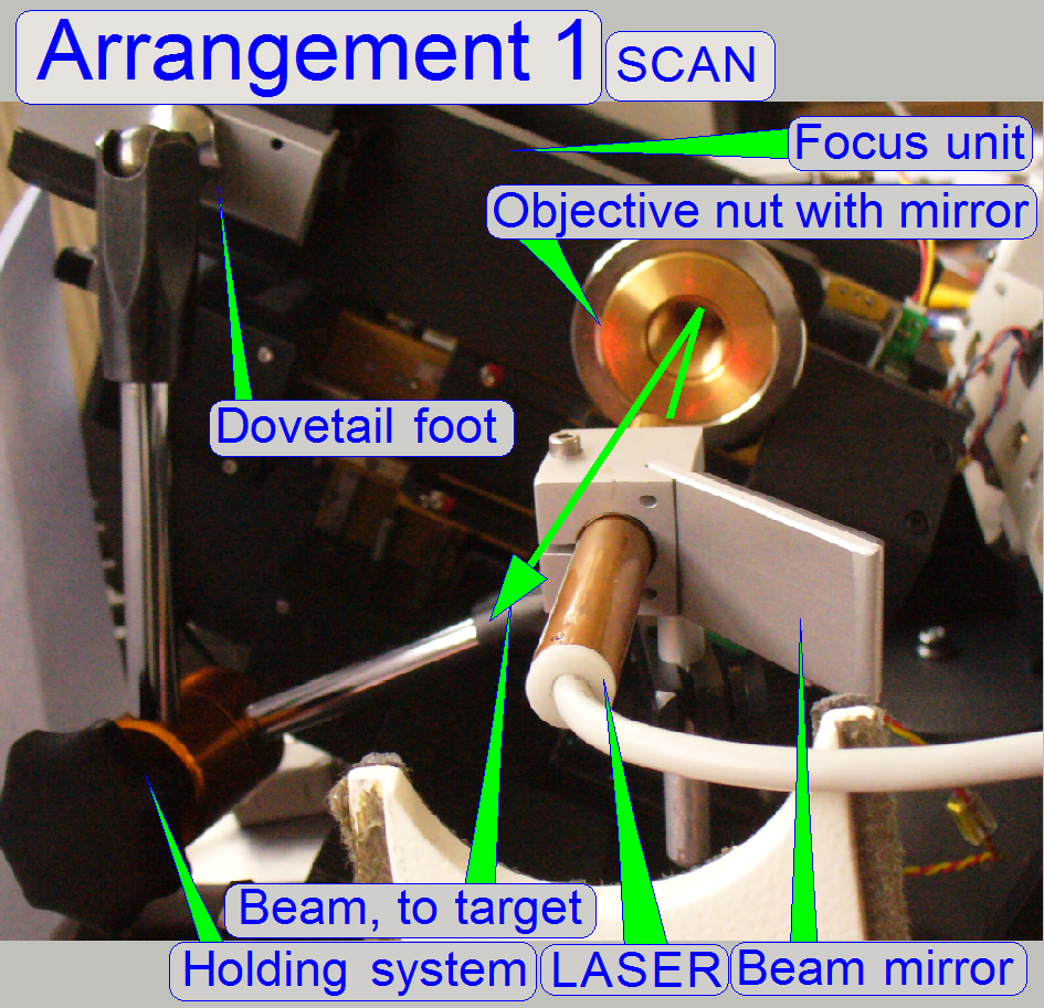
The mirror is
mounted at an angle of 45º onto the LASER source holder and may be used to
reflect the beam sideways, onto the wall.
The LASER source holder can be mounted so, that the
beam passes the opposite side (or any side) of the LASER source mounting where
no mirror is mounted.
Into the “objective position
·
If the objective position is already
adjusted please do not loosen the objective nut (or the objective counter nut)
during removing the objective; otherwise the adjusted objective position will
be lost!
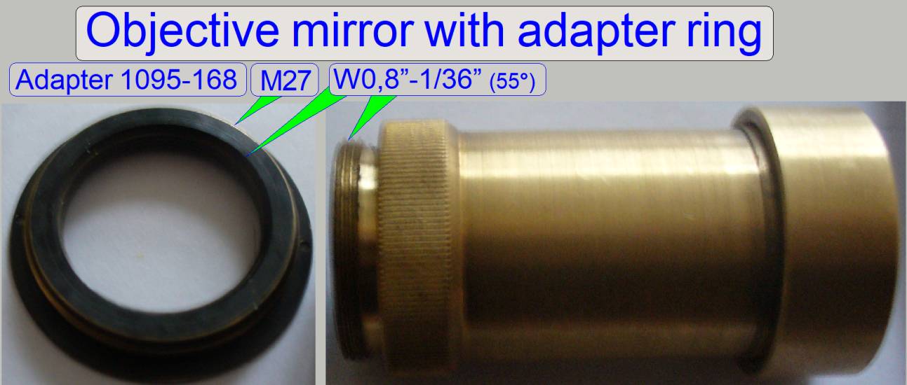
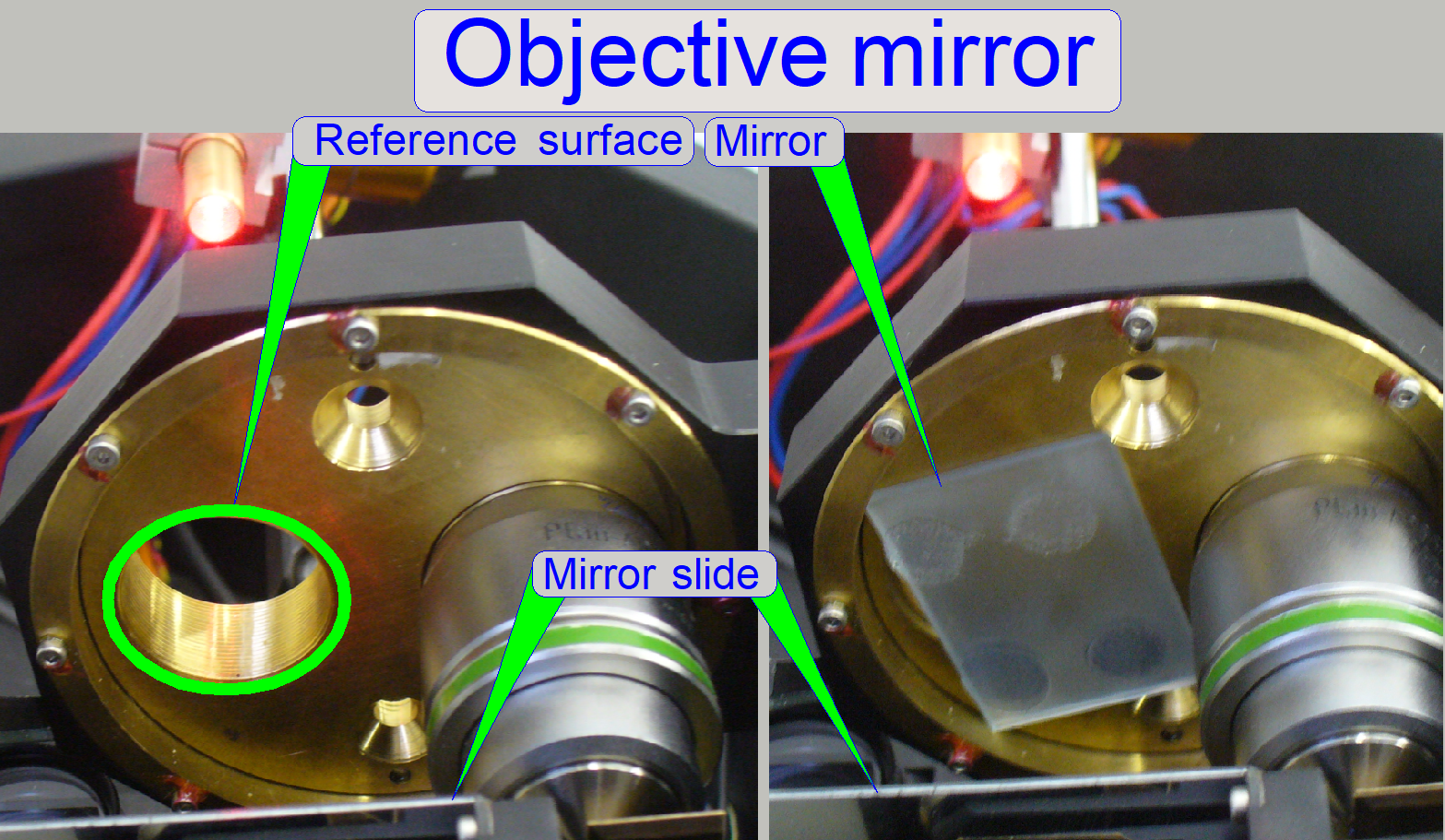
This mirror defines the plane of the objective pupil;
the mirror is mounted perpendicular to the optical axis and is used to arrange
the entire configuration for the real adjustment.
After the configuration is arranged, this mirror is
not needed for the real adjustment.
See also “Arrangement 1” and
“Arrangement 2”.
Remark
· Because
the plane of the objective pupil has to be checked more times during the
adjustment, we recommend to remove both objectives (the 20x and the 40x
objective or the dummy objective also).
·
By rotating the objective disc manually
into the objective position 1 or 2 respectively, you can easily and quickly
“switch” between the “Arrangement 1” and the “Arrangement 2”.
Another solution
A simple mirror may also be used to define the
objective plane, instead of the objective mirror; see also “Arrangement
Dismount the objective by unscrewing only the
objective from the objective nut; do not modify the adjusted objective position
(the wrenches should not be used).
- The reference surface of the objective nut should be smooth;
stickers / labels should not disturb the smoothness of the reference
surface.
- Put the mirror onto the reference surface of the objective nut as
shown and find a well reachable place on the wall for the screen; use the
laser beam.
- Stick the screen onto the wall with the laser beam in the center of
the marker.
- Then remove the mirror.
Important
The actual reference surface position should be
checked more times during the adjustment process.
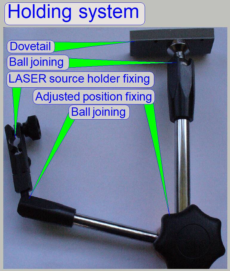
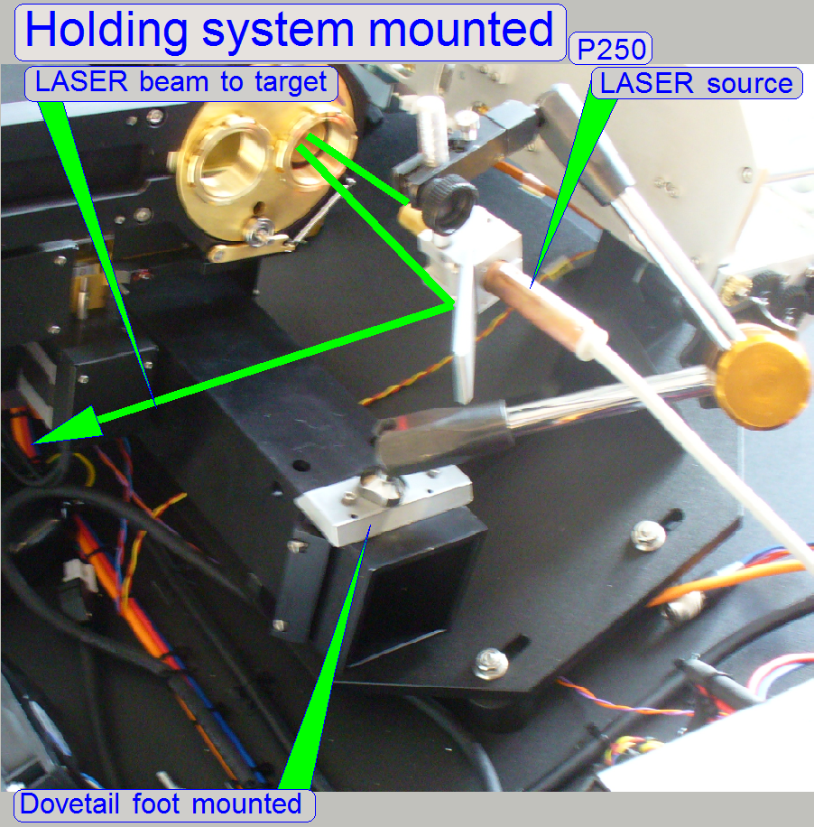
To mount the LASER source in the correct position over
the focus unit, this holding system is used; the dovetail foot is mounted onto
the truss, onto the position of the turret unit fixing clamp. Onto the other
end of the holding system the LASER source holder fixing with mirror is
mounted.
·
You can also use any holding system that
allows the position adjustment of the LASER source holder with mirror in the
X-, Y- and Z-direction of the room co-ordinates.
![]() Holding systems from NOGA “http://www.noga.com/”
Holding systems from NOGA “http://www.noga.com/”
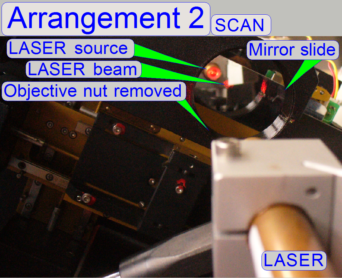
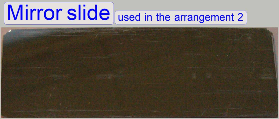 The
mirror slide is used in the “Arrangement 2”; it deflects the LASER
beam according to the inclination of the specimen holder; the angle of the
inclination is added to the angle of the LASER beam and so the LASER beam is
deflected more, less or equal in relation to the “Arrangement 1”.
The
mirror slide is used in the “Arrangement 2”; it deflects the LASER
beam according to the inclination of the specimen holder; the angle of the
inclination is added to the angle of the LASER beam and so the LASER beam is
deflected more, less or equal in relation to the “Arrangement 1”.
Remark
The LASER beam will be reflected on the surface of a
simple slide also; so it is not important to use a mirror slide in the
arrangement 2; but the description refers always to “the mirror slide”!
· Please
check the shape and the surface of the no-coated slide carefully before using
it during the adjustment!
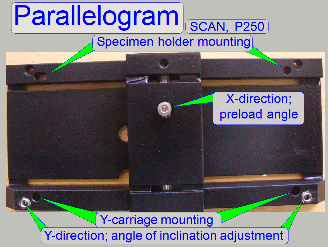
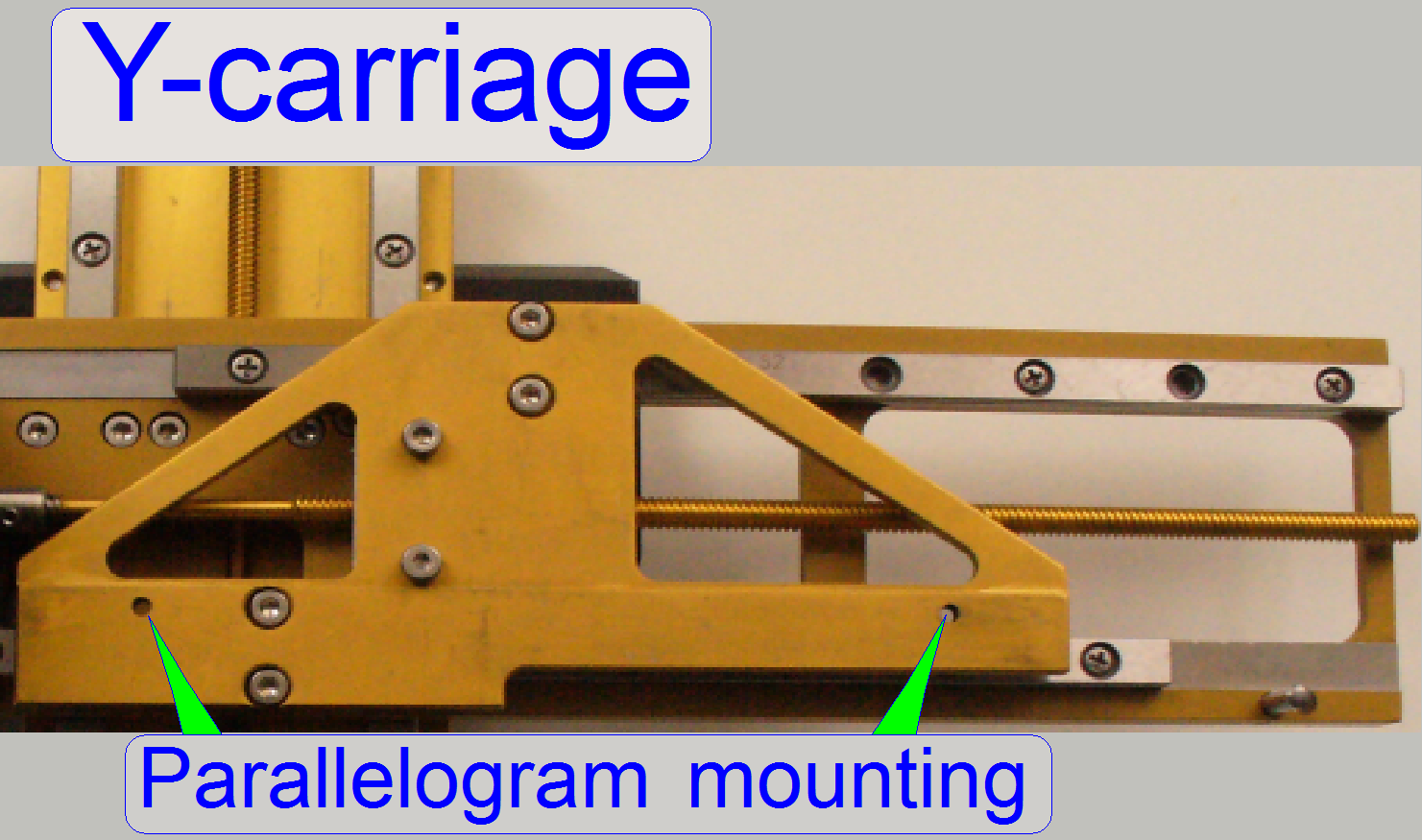
This component ensures the parallel shifting of the
X-Y plane if the focus pin moves the slide toward or away from the objective
(in Z-direction).
· The
position of the component in relation to the X-Y-plane of the slide defines the
perpendicularity of the optical axis in relation to the slide surface (tissue).
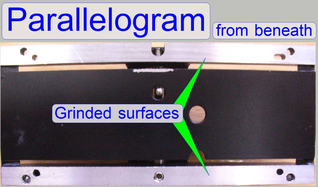
The connection surfaces to the Y-carriage and the
specimen holder are grinded to ensure the parallelism of both connected
components.
Parallelogram movement
limiter
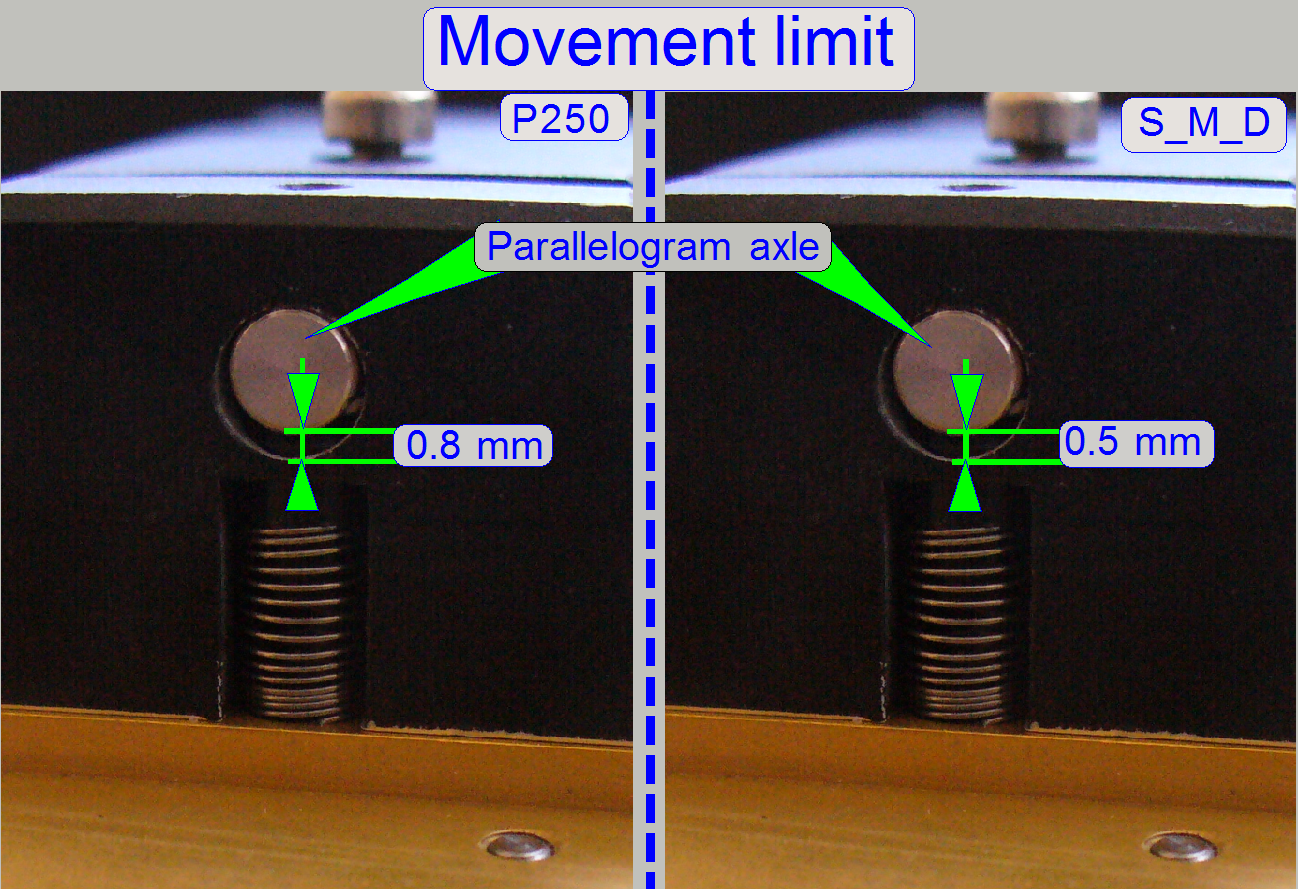 The
allowed movement of the parallelogram is limited to be 0.8 mm over all in
P250 and S_M_D_II-type scanners (in opposite to S_M_D = 0.5mm). This limit is
constant and can not be adjusted separately. To adjust the correct limiter
position a fitting plate is used. The thickness of the used fitting plate
defines the correct position of the entire parallelogram and so the position of
the parallelogram axle in relation to the limiter also.
The
allowed movement of the parallelogram is limited to be 0.8 mm over all in
P250 and S_M_D_II-type scanners (in opposite to S_M_D = 0.5mm). This limit is
constant and can not be adjusted separately. To adjust the correct limiter
position a fitting plate is used. The thickness of the used fitting plate
defines the correct position of the entire parallelogram and so the position of
the parallelogram axle in relation to the limiter also.
How to check the acting range of the parallelogram and the
movement limiter?
1)
Move the stage with the service program
nearly into the middle of the scan area.
2)
Set the focus motor to Home 1,2
3)
Set the focus motor to the position -300
steps.
4)
Check the position of the parallelogram
axle in relation to the limiter; in this position a small gap should exist and
the focus pin should be in connection to the slide.
5)
Set the focus motor to the position +1300
steps.
6)
Check the position of the parallelogram
axle in relation to the limiter; in this position a small gap should also
exist.
· If a
small gap on both limit positions can be found, the focus pin is always in
connection with the slide and the inclination angle adjustment of the slide is
finished (the adjustment of the parallelogram position), the movement limit of
the parallelogram is well defined.
· During
the adjustment procedure of the parallelogram position please check this
behavior more times; even if the inclination angle of the slide in X-direction
was modified!
· If
there is no gap in the appropriate limit position or the slide is not in
connection with the slide over the entire focus range, the inclination of the
slide in X-direction may be wrong or the thickness of the fitting plate may be
selected incorrectly.
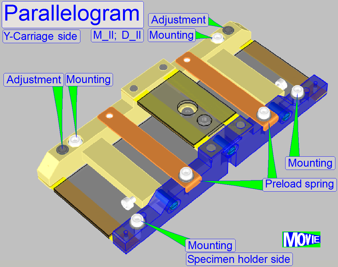
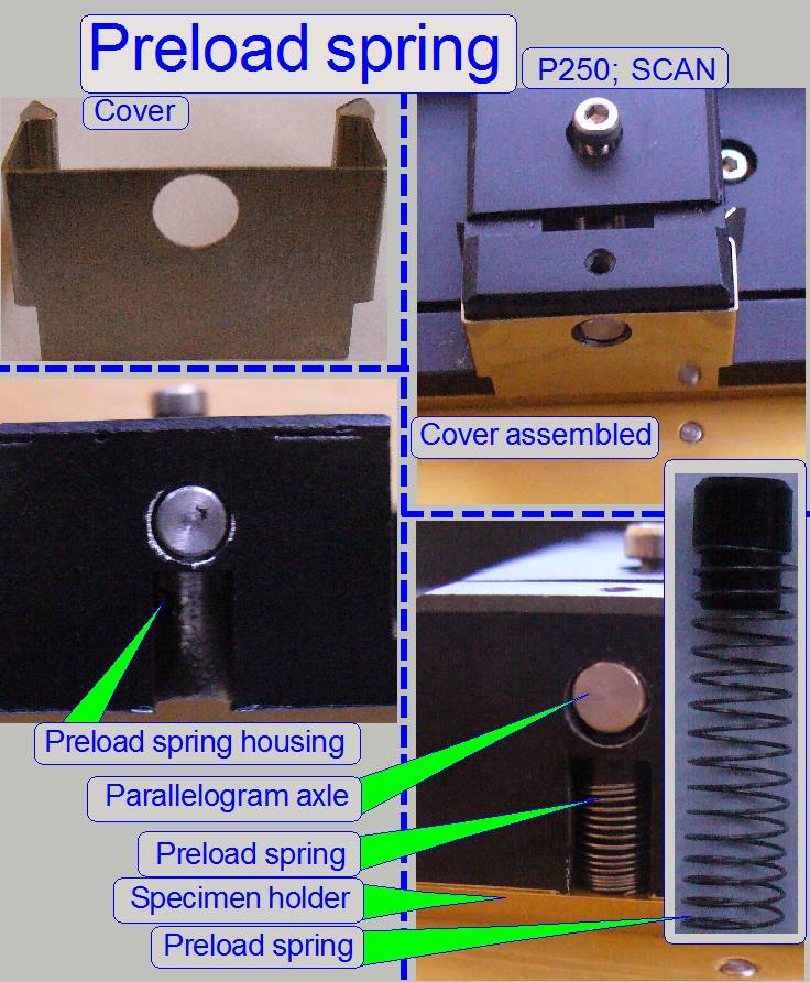 The
preload spring is used to create a force of the specimen holder against the focus pin, so a mechanical preload is created. With
this solution the slide is always in connection with the focus pin during
focusing or specimen holder movements in the scan process.
The
preload spring is used to create a force of the specimen holder against the focus pin, so a mechanical preload is created. With
this solution the slide is always in connection with the focus pin during
focusing or specimen holder movements in the scan process.
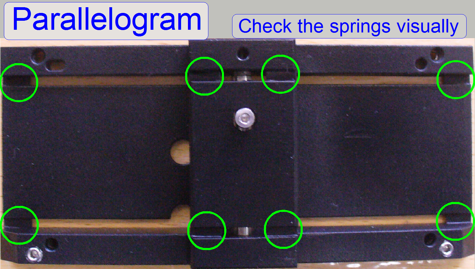 Before
you mount the parallelogram (even if a used one should be mounted) you have to
check it of functionality, visually. The parallelogram is correct if all 8
mounting spring leafs are not bent or broken. The flat springs are the most
sensitive parts of the parallelogram.
Before
you mount the parallelogram (even if a used one should be mounted) you have to
check it of functionality, visually. The parallelogram is correct if all 8
mounting spring leafs are not bent or broken. The flat springs are the most
sensitive parts of the parallelogram.
·
Compare the look of the springs to each
other!

The fitting plate is used to define the parallelogram limiter
so, that the limiter does not limit the parallelogram movement in the range
between -300 and +1300 focus steps; the thickness of the selected fitting plate
is correct if there a small gap on the limiter exists if the focus position of
-300 steps is reached and even so, there have also to be a small gap if the
focus position of +1300 steps is reached.
· The fitting plate is mounted between the
Y-carriage and the parallelogram.
· The drillings and edges have to be burred;
the surface should be smooth.
· The nominal thickness of the fitting plate
can be 0.1 mm, 0.2 mm, 0.3 mm, 0.4 mm, 0.5 mm or
any combination of two fitting plates.
· The thickness of the fitting plate is
often found between 0 (no fitting plate used) and 0.5 mm.
· The fitting plate has to cover the entire
mounting surface of the parallelogram; see also below “Mount the parallelogram”.
· In exceptions, the fitting plate might be
mounted between the specimen holder and the parallelogram (if a negative value
for the fitting plate thickness have to be reached); in this cases, there have
not to be a fitting plate on the mounting surface between parallelogram and
Y-carriage; the adjustment bolt(s) are always used on the side, where the
fitting plate is placed.
Inclination angle adjustment in X-direction
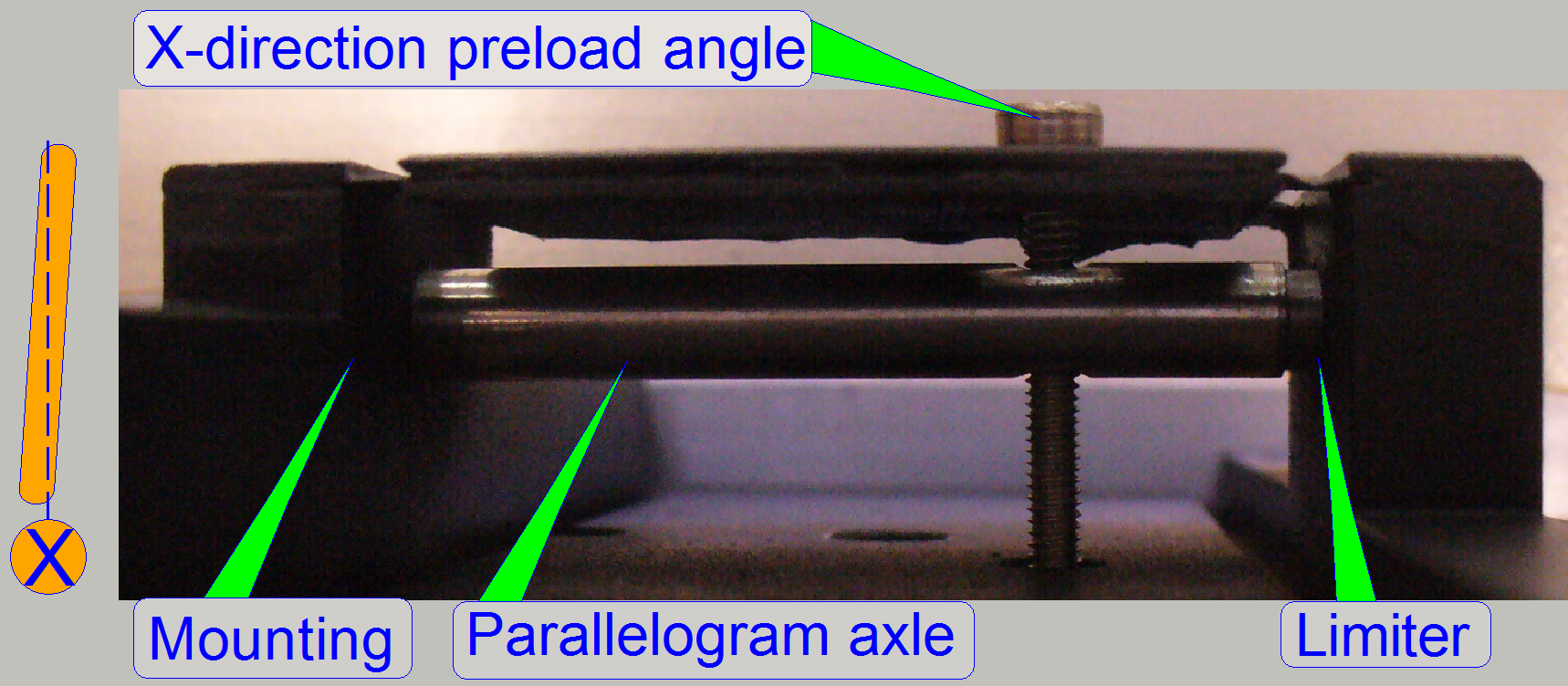 This
adjustment bolt is used to define the angle of the parallelogram and so the
angle of the specimen holder (slide). By screwing the X-direction preload angle
bolt, the inclination angle of the parallelogram can be adjusted to zero (the angle of inclination
between X-min and X-max of the scan area).
This
adjustment bolt is used to define the angle of the parallelogram and so the
angle of the specimen holder (slide). By screwing the X-direction preload angle
bolt, the inclination angle of the parallelogram can be adjusted to zero (the angle of inclination
between X-min and X-max of the scan area).
IMPORTANT: The limit of the parallelogram movement limiter is
affected also and has to be checked always after driving the bolt.
![]() “How to check the acting range of the parallelogram”
“How to check the acting range of the parallelogram”
Inclination angle adjustment in
Y-direction
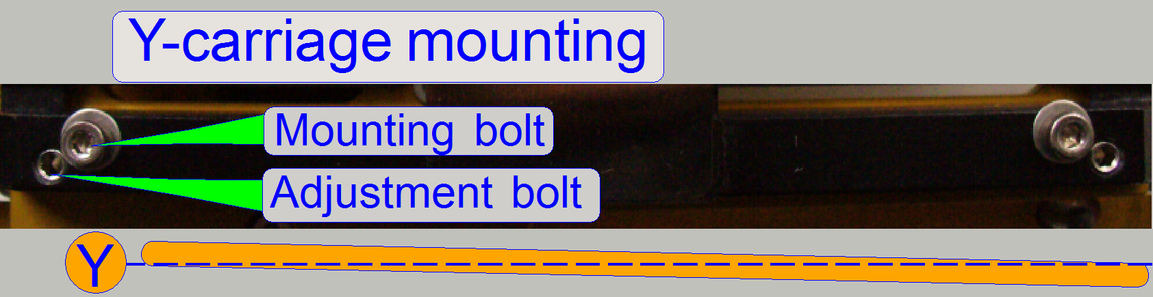 With
this adjustment the angle of inclination in Y-direction is reduced /
eliminated; it means the inclination angle
between Y-min and Y-max of the scan area.
With
this adjustment the angle of inclination in Y-direction is reduced /
eliminated; it means the inclination angle
between Y-min and Y-max of the scan area.
· By loosening the mounting bolt and
tightening the adjustment bolt or by loosening the adjustment bolt and
tightening the mounting bolt, the angle of the inclination in Y-direction is
modified.
· The adjustment is done only on one side;
the adjustment bolt of the opposite side should be fully loosened (or removed)!
· If the adjustment on the actual side does
not deliver the desired result, change the adjustment bolt to the opposite side
and execute the adjustment there.
 On this
side the parallelogram is mounted together with the fitting plate (if needed).
On this
side the parallelogram is mounted together with the fitting plate (if needed).
· Place the fitting plate so, that the
entire (grinded) mounting surface of the parallelogram is covered by the
fitting plate.
· If the thickness of the fitting plate has
to be modified, dismount the entire parallelogram with specimen holder,
exchange the fitting plate and mount the parallelogram again (the two mounting
bolts).
On the opposite side of the parallelogram the specimen
holder is mounted, usually without fitting plate and without adjustment bolts.
In exceptions, the fitting plate is mounted between
the specimen holder and the parallelogram (if a negative value for the fitting
plate thickness have to be reached); in this cases, there have not to be a
fitting plate on the mounting surface between parallelogram and Y-carriage; the
adjustment bolt(s) are always used on the side, where the fitting plate is
placed.
 In
“Arrangement 1” the position of the entire scanner, more precise, the
position of the objective nut will be defined; in “Arrangement 2” the
position of the specimen holder in relation to the previous arrangement will be
defined. In other words, the plane defined by the objective mirror is used as
reference plane and the plane of the specimen holder with the mirror slide will
be adjusted to the reference plane. Therefore it is important, that the found
position of the reference plane during the “Arrangement
In
“Arrangement 1” the position of the entire scanner, more precise, the
position of the objective nut will be defined; in “Arrangement 2” the
position of the specimen holder in relation to the previous arrangement will be
defined. In other words, the plane defined by the objective mirror is used as
reference plane and the plane of the specimen holder with the mirror slide will
be adjusted to the reference plane. Therefore it is important, that the found
position of the reference plane during the “Arrangement
This means:
· The
position of the components must not be altered until proper alignment is
reached.
Please
do not move
· The
table
· The
entire scanner or the truss
· The
holding system (it may occur if the parallelogram bolts are driven)
·  The LASER source (it may occur if
the parallelogram bolts are driven) and
The LASER source (it may occur if
the parallelogram bolts are driven) and
· The
screen until the entire adjustment is not finished correctly.
 If one
of the named components changed its position, please rotate or insert the
objective mirror into the optical axis again, remove the target and stick it
again onto the wall in the right beam position; or start with “Arrangement
If one
of the named components changed its position, please rotate or insert the
objective mirror into the optical axis again, remove the target and stick it
again onto the wall in the right beam position; or start with “Arrangement
 Change
the objective to the objective mirror.
Change
the objective to the objective mirror.
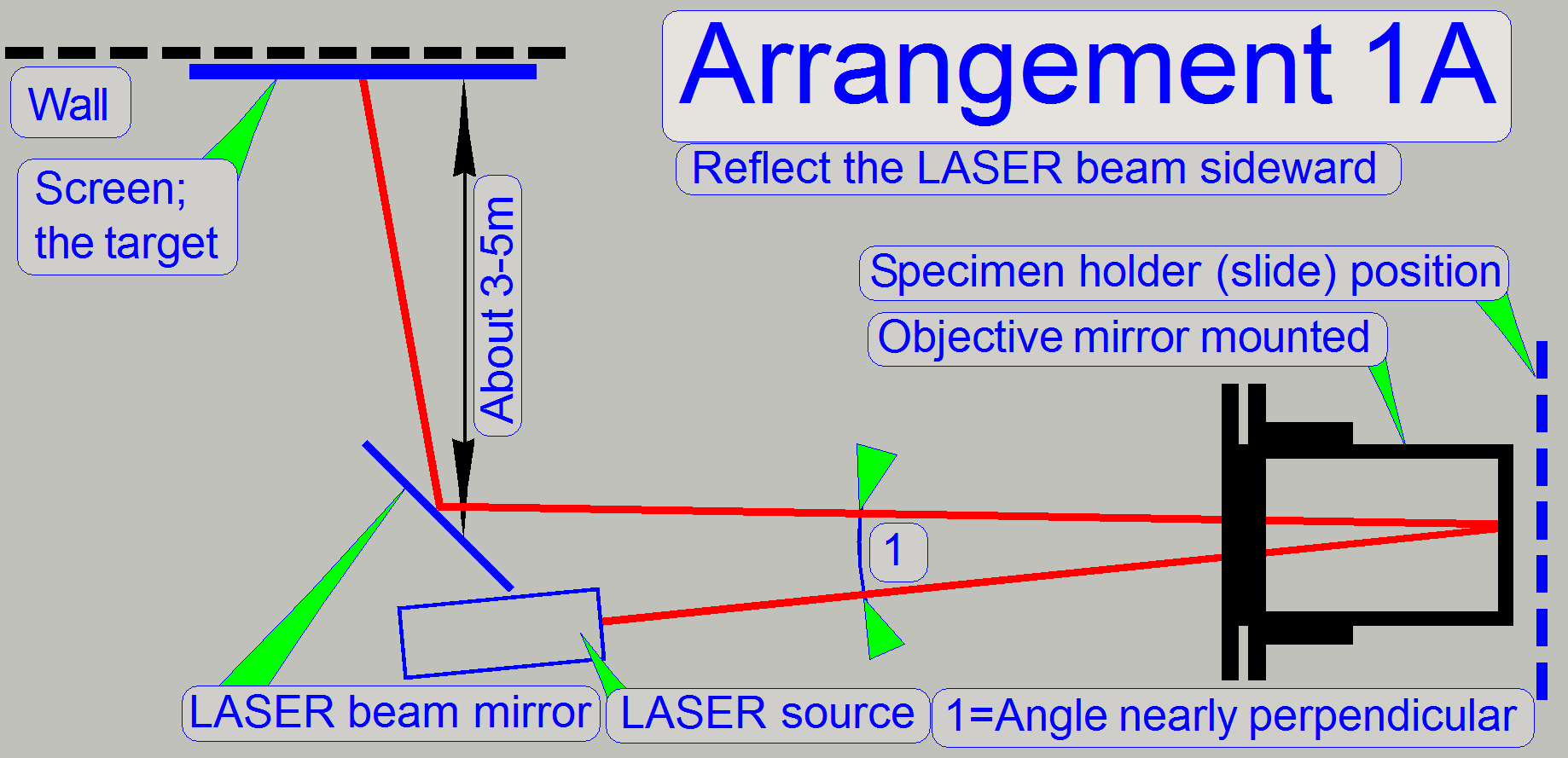
Mount the LASER source holder with the holding system
over the objective nut.
Adjust the position of the laser source holder so,
that the LASER beam is reflected by the objective mirror to the LASER beam
mirror in an angle that is nearly perpendicular.
The angle of the laser beam, reflected by the
objective mirror should be as small as possible; so the error of the adjustment
will be small also.
· To
reach this, the LASER beam source holder should be mounted at a large
distance from the objective nut.
By positioning the entire scanner and the holding
system find a well reachable and visible part on the wall (use the LASER beam)
and stick the screen onto the wall with the LASER beam in the center of the
marker position.
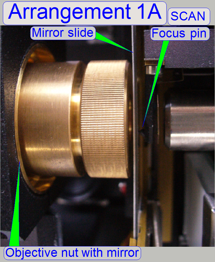
Arrangement 1B
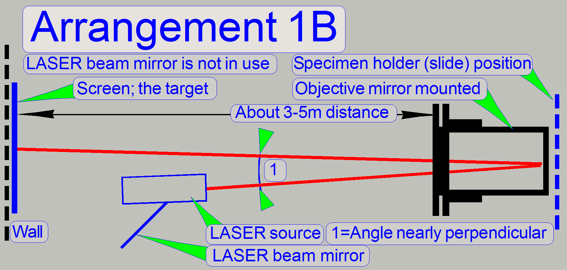
The only difference to the arrangement 1A is the use
of the LASER beam mirror.
· In the
arrangement 1B the LASER beam mirror is not used.
· Important: The LASER beam source
holder should be mounted at a large distance to the objective nut.
Arrangement
· 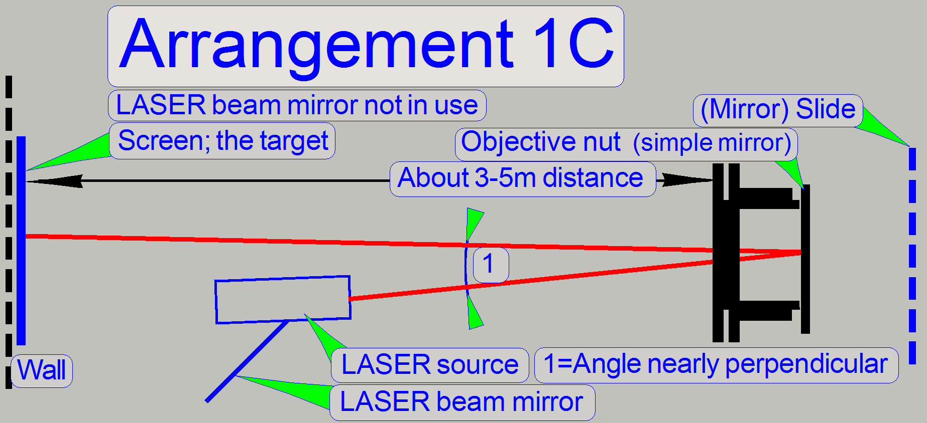 The
LASER beam mirror may be used or not like shown in the arrangement 1A or 1B.
The
LASER beam mirror may be used or not like shown in the arrangement 1A or 1B.
· The main
difference to the arrangement 1A or 1B is the use of a “simple mirror” on the
objective nut instead of the objective mirror.
This version needs more accuracy during the
preparation of the adjustment
· Important: The LASER beam source
holder should be mounted at a large distance to the objective nut.
Arrangement
2A
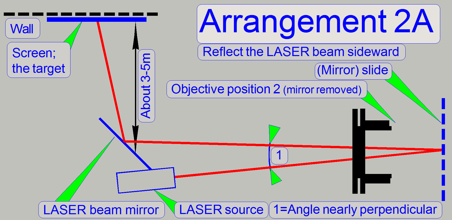 Rotate
the objective disc into the objective position 2 (there is no objective
present).
Rotate
the objective disc into the objective position 2 (there is no objective
present).
If arrangement
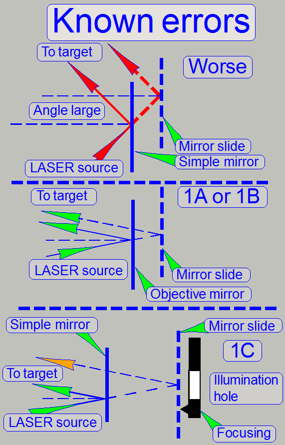
See also: Known errors
Insert the mirror
slide (manually); the LASER beam should be visible on the
screen again.
With the X-Y-stage tools of the service program find a
position for the specimen holder nearly in the middle of the mirror slide’s
scan area.
Set the focus position with the service program to
-300 steps and +1300 steps and check the movement of the LASER beam on the
screen several times.
Arrangement
2B
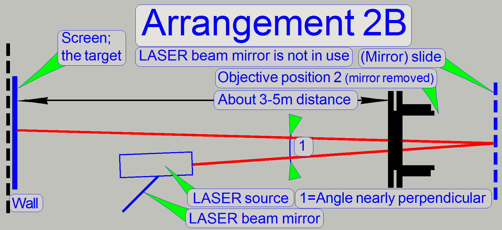 The
only difference from arrangement 2A is the use of the LASER beam mirror;
depending on the used arrangement 1.
The
only difference from arrangement 2A is the use of the LASER beam mirror;
depending on the used arrangement 1.
· In the
arrangement 2B the LASER beam mirror is not used.
 The mirror
position difference between the mirror slide and the objective mirror in the
arrangement 1 and 2 contains automatically a measurement error.
The mirror
position difference between the mirror slide and the objective mirror in the
arrangement 1 and 2 contains automatically a measurement error.
· To
reduce adjustment errors, the angle of the LASER beam should be as close to
perpendicular as possible!
· To
reach an angle of the LASER beam close to perpendicular, the LASER
source holder should be mounted far away from the objective nut as much as
possible and the reflected LASER beam should pass the LASER source as close as
possible.
Arrangement 1A or 1B
If the objective mirror is used, the angle is always
close to perpendicular (very small), because the mirror surface is small and
the LASER beam is routed in a tube.
Arrangement
To minimize the error of the adjustment, the angle of
the LASER beam should be close to perpendicular and should match the
illumination hole of the focusing part.
· Arrange
the position of the LASER source precise with a very small angle!
Because a simple mirror is used on the objective
mounting nut, the distance of the simple mirror to the mirror slide
is more than in the arrangement 1A or 1B; there is no tube
part used to route the LASER beam and the mirroring
surface of the simple mirror is large; the error of the
adjustment will also be more.
·
Please take all this into account if the tools will be arranged!
Prepare the scanner for
the adjustment
1)
Remove the upper housing
cover.
3)
Remove the entire
preview unit
4)
Set the working position of
the objective changer unit to the objective position 1.
5)
Remove the
objective changer drive unit.
6)
Dismount the 20x
objective.
7)
Mount the
objective mirror.
8)
Dismount the 40x
or the dummy objective.
9)
Mount the holding system onto
the truss, use the mounting bolts of the upper clamp and tighten the dovetail
foot.
10) Mount
the LASER source holder with LASER source as shown in the “Arrangement 1A or 1B”; see
also Known errors
11) By
positioning the entire scanner find a well reachable / visible part on the wall
(use the LASER beam) and stick the screen onto the wall with the LASER beam in
the center of the marker position.
12) If the
position is found as desired and the screen is stuck onto the wall the “Arrangement
1” is finished.
· If the
screen is stuck onto the wall the entire arrangement position must not be
altered until the entire adjustment is finished; see also The principle of the adjustment.
· If one
of the used components changed its position, please rotate / insert the
objective mirror again into the optical axis and check / adjust the “Arrangement 1”
again.
13) Rotate the objective disc into
the objective position 2 manually.
14) If the
arrangement
15) Insert
the mirror slide (manually); the LASER beam should be visible on the screen
again; see also: “Images of the
adjustment steps”.
16) With
the X-Y-stage tools of the service program find a position for the specimen
holder nearly in the middle of the mirror slide’s scan area.
17) Set
the focus position with the service program to -300 steps and +1300 steps more
times and check the movement of the laser beam on the screen.
18) Set
the focus position to -300 steps.
19) Adjust
the parallelogram limiter position by selecting the appropriate thickness of the fitting plate (if
required).
20) Check the behavior
of the parallelogram movement limiter.
21) Incline the mirror
slide in Y-direction so, that the LASER beam moves in direction
to the center of the target.
22) Check the
momentarily adjustment.
23) Set
the focus position to +500 steps.
24) Repeat
the previous 3 steps until the inclining of the mirror slide in Y-direction
will not improve the result.
25) Check
the “Arrangement 1”
26) Incline the mirror
slide in X-direction so, that the LASER beam moves in
direction to the center of the target.
27) Check the
momentarily adjustment.
28) In the
focus positions -300 steps and +1300 steps check the gaps of
the movement limiter.
29) Set
the focus position to +500 steps.
30) Repeat
the steps from step 21 until only a movement inside the limits of the target
can be expired.
31) Check
the “Arrangement 1”
32) Check the
momentarily adjustment.
33) Check
the entire adjustment near to the limits of the scan area; see also: “Images of the
adjustment steps”
34) Check the behavior
of the parallelogram movement limiter.
35) Check
the “Arrangement 1”
36) Move
the stage to the center of the scan area and check the movement of the LASER
beam on the target in the focus positions -300 steps, +500 steps and +1300
steps.
37) Check the behavior
(acting range) of the parallelogram movement limiter.
38) Check
the entire adjustment near to the limits of the scan area; see
also: “Images of the
adjustment steps”
· If the
movement of the LASER beam on the target is inside the limits in the named
positions, the adjustment is finished and the scanner can be assembled.
39) Mount the
objectives.
40) Mount the
objective changer drive unit.
43) Check / adjust the
position of the magazine unit.
44) Check / adjust the
correct position of the specimen
holder fixing fork.
45) Check / adjust the
objective position
46) Check
/ define the scan area
47) If the
scan area was modified, please execute the preview
calibration also.
48) Check / adjust the
darkfield preview.
Check the momentarily
adjustment
Move the stage near to the center of the scan area and
check the beam behavior on the target in the focus positions
P250; SMD_II: -300
focus steps +500 focus
steps and +1300 focus steps.
S_M_D: 1200 focus steps 1600 focus steps and
2000 focus steps.
![]() Focus unit P250, S_II, M_II, D_II, SMD
Focus unit P250, S_II, M_II, D_II, SMD
The LASER beam should move only a little bit.
· Check the behavior
of the parallelogram movement limiter
Check the behavior of the
parallelogram movement limiter
· In the
positions -300 focus steps and +1300 steps please check the limit of the parallelogram
limiter; a small gap should exist.
· In the
position -300 focus steps please check the connection of the slide with the
focus pin; the focus pin should touch the slide.
If any requirement is not fulfilled, select the
correct thickness of the fitting plate.
Incline the slide in
X-direction
 Move
the stage nearly into the center of the scan area.
Move
the stage nearly into the center of the scan area.
Set the focus motor to the position +500 steps.
Drive the X-direction preload angle bolt carefully in
the appropriate direction; the beam should move in direction to the center of
the marker circles.
Check the behavior
of the parallelogram movement limiter
Incline the slide in
Y-direction
 Move
the stage nearly into the center of the scan area .
Move
the stage nearly into the center of the scan area .
Set the focus motor to the position +500 steps.
Modify the
position of the parallelogram in Y-direction; the beam should
move in direction to the center of the marker circles.
Dismount the objective and mount the objective mirror
1.
 With the program SlideScannerService.exe set
the X-Y-stage to the positions Y-Home1,2 and X-Home1,2.
With the program SlideScannerService.exe set
the X-Y-stage to the positions Y-Home1,2 and X-Home1,2.
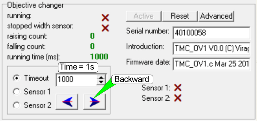
2.
In the tab “Objective changer” move the objective (position),
to be dismounted or mounted into the working position.
3.
Select the option “Time out”, set a numerical value of
about 1000ms and press the button Backward.
4.
Dismount / mount the objective (mirror). Hold the
mounting nut with the delivered wrench and remove / mount the objective
(mirror) by hand.
·
Please do not modify the objective nut position;
otherwise, the adjusted focus position will be lost!
5.
Select the appropriate sensor and press the button forward;
the actual dismounted position or the mounted objective should move into the
working position.
6.
Repeat the steps 2 to 5 with the other objective
(position), if necessary.
7.
If the 40x objective was mounted, check / select the
thickness of the cover slip; see also “The 40x objective”.
Images of the adjustment
steps; P250
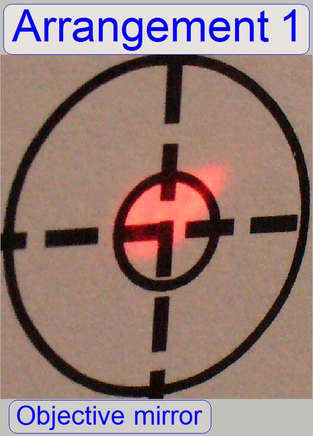
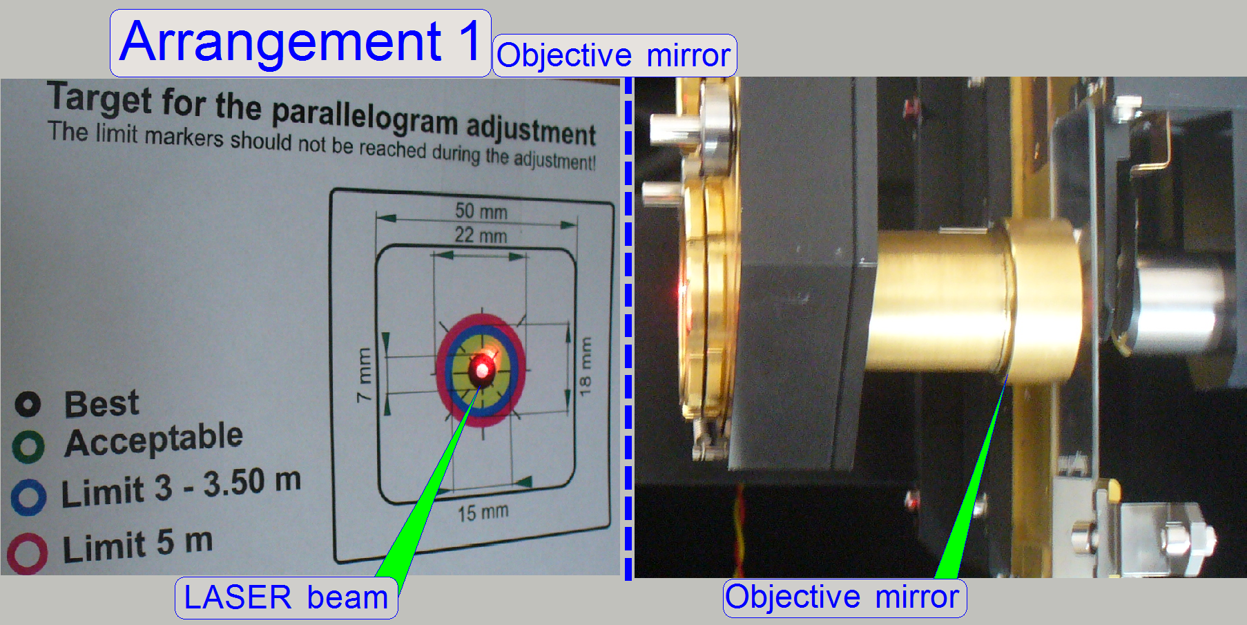 The
LASER beam is shown after sticking the screen onto the wall (after finishing the arrangement 1).
The
LASER beam is shown after sticking the screen onto the wall (after finishing the arrangement 1).
· The
distance of the screen to the scanner’s objective nut is ~4.8m.
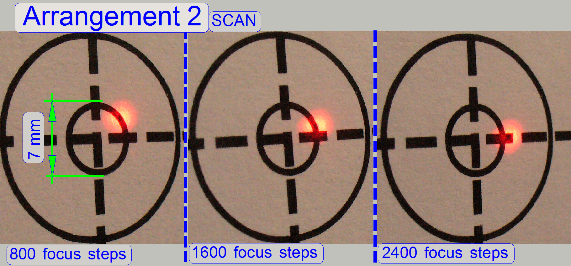
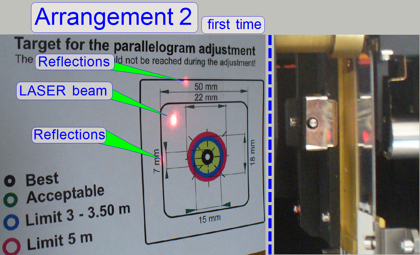 The
mirror slide is inserted; the LASER beam is shown first time with the mirror
slide; nearly in the center of the scan area.
The
mirror slide is inserted; the LASER beam is shown first time with the mirror
slide; nearly in the center of the scan area.
Images
of the adjustment steps; SCAN
Objective
mirror and arrangement 1
Arrangement
2; objective nut with mirror removed
Adjustment
results; SCAN
The distance between scanner and
wall is 3.10m; the pictures are taken nearly in the middle of the scan area.
·
 Check the
adjustment with the stage skew check; see “Stage skew check”
Check the
adjustment with the stage skew check; see “Stage skew check”
·
Check the scan area; see “Scan area”, and check the preview in SlideScanner.exe or execute the preview calibration respectively, if
required!