Focus unit; S_II
For technicians and
partly for sales managers!
These instructions describe the
procedures to install and adjust the focus unit for Pannoramic SCAN _II type scanners
(S_II).
To help resolve problems with the
focus unit a hardware description of the implemented components and adjustment
procedures are added.
The focus unit is designed to fulfill the
following tasks
·
Holding the
objectives Plan-APOCHROMAT 20x/0.8 and Plan-APOCHROMAT 40x/0.95 in the center of
the focus range (realized by the objective changer)
· Focusing of tissues during the scan process on slides
with a slide thickness of 0.95 ~ 1.20mm
(done by the focusing part)
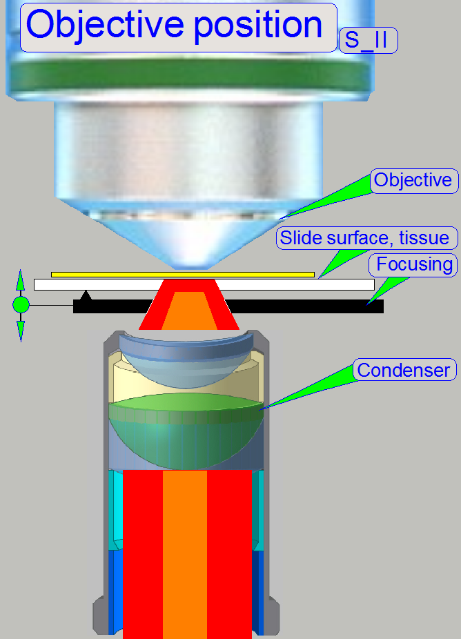
· Concentrating the illumination light to the field of
view (FOV) during brightfield scan procedures (done by the condenser).
· Insuring a dark background during fluorescent scan
procedures (realized by the mechanical shutter)
· Exchanging the objective magnification between two
scan sessions; BF or FL (realized by the objective changer)
Principle of shutter
mechanics
Hardware limits and
shutter on or off
Dismount or
mount the focus unit
·
For safety regulations regarding
human health and scanner functionality please refer to: Precautions
Focus unit
Modifications since summer 2016
Main improvements
- The slide
thickness may be now 1.2mm max; therefore
- The motor
resolution is now 400full-steps or 6400micro-steps/revolution.
- More details
can be found in Improvements_2016
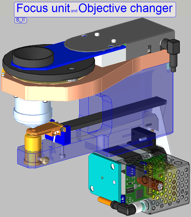
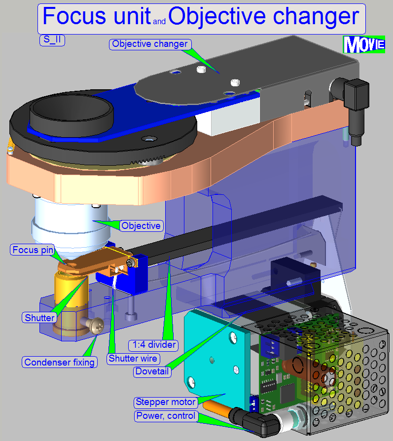 The described focus unit is a component of the Pannoramic scanner family and contains the following main parts:
·
The focusing part (driven by the focus stepper motor)
·
The
objective with mounting into the objective changer disc
·
The
condenser with its position fixing
·
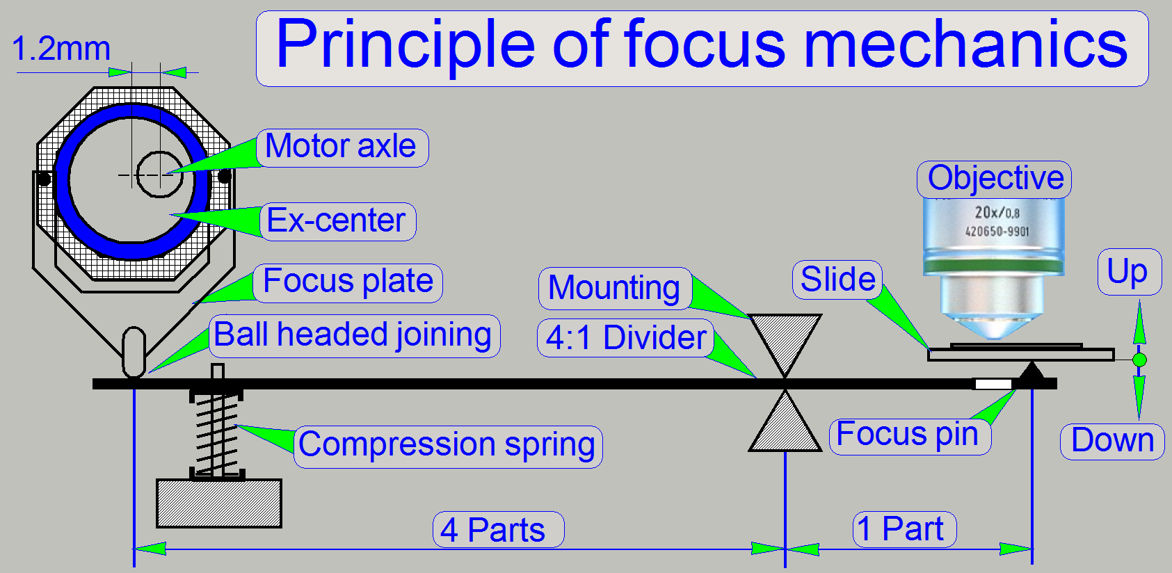
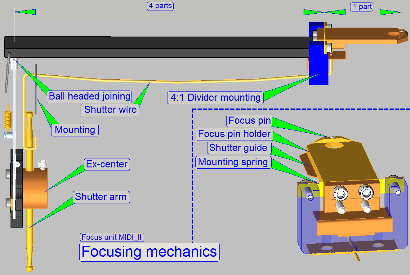
The focusing mechanics
(Ex-center, 4:1 divider, Focus pin)
·
The shutter
mechanics (Shutter arm, shutter wire, shutter guide)
·
The objective changer unit holds the objectives and
allows a consecutive use of different magnifications between two scan sessions.
The focus unit gives the possibility of
focusing the FOV (field of view, seen by the scan camera by 1 exposure)
automatically during the scan process of the sample.
The unit was developed for
the use of objectives
of the following types:
Plan-APOCHROMAT
20x/0.8 and Plan-APOCHROMAT
40x/0.95
The objective type
“Plan-Apochromat” contains several, special chromatically and spherically
corrections and delivers so an image of very high color trueness with very
small spherical aberration.
If the mechanical dimensions
do not exceed the size of the Plan-APOCHROMAT 40x0.95 type objective, the
mechanical mounting is identical and the focus distance of the objective to the
tissue is not closer then 0.25mm, other kind of objectives can be used also but
it is strongly not recommended!
·
Always check with 3DHISTECH first when a different
objective type should be used!
 The shutter mechanics covers the
condenser and this way, during fluoresce scan sessions, the bright field
illumination path is broken. The two commands, condenser cover off and
condenser cover on are identical with the physical lower and upper limits of
the focus unit.
The shutter mechanics covers the
condenser and this way, during fluoresce scan sessions, the bright field
illumination path is broken. The two commands, condenser cover off and
condenser cover on are identical with the physical lower and upper limits of
the focus unit.
The exchange of the focus unit is possible
- If the stepper motor
or its electronics for the focus unit is faulty
-
If the shape of any part is deformed or a part is broken.
-
If the focus unit has any fault and
you are unable to fix it.
Requirements
- Service
program for Pannoramic scanners (SlideScannerService.exe)
with actual license file
- Pannoramic
Scan Software (version 1.21. or higher) and Pannoramic Viewer software
(SlideScanner.exe, SlideViewer.exe) with dongle or license file
- 1.5, 2.5, 3 and
- Hardware and construction knowledge of
Pannoramic type scanners
 Attention Do not mix the
versions of SlideScanner.exe and SlideScannerService.exe! Always use these
programs with the same version number. Otherwise the SlideScannerService.exe
program could produce unwanted results and SlideScanner.exe does not work
correctly or even freeze!
Attention Do not mix the
versions of SlideScanner.exe and SlideScannerService.exe! Always use these
programs with the same version number. Otherwise the SlideScannerService.exe
program could produce unwanted results and SlideScanner.exe does not work
correctly or even freeze!
Focus
unit with objective changer
The focus unit with objective
changer is developed for Pannoramic SCAN_II and MIDI_II scanners, based on the
focus unit of the P250 and is implemented since summer 2016.
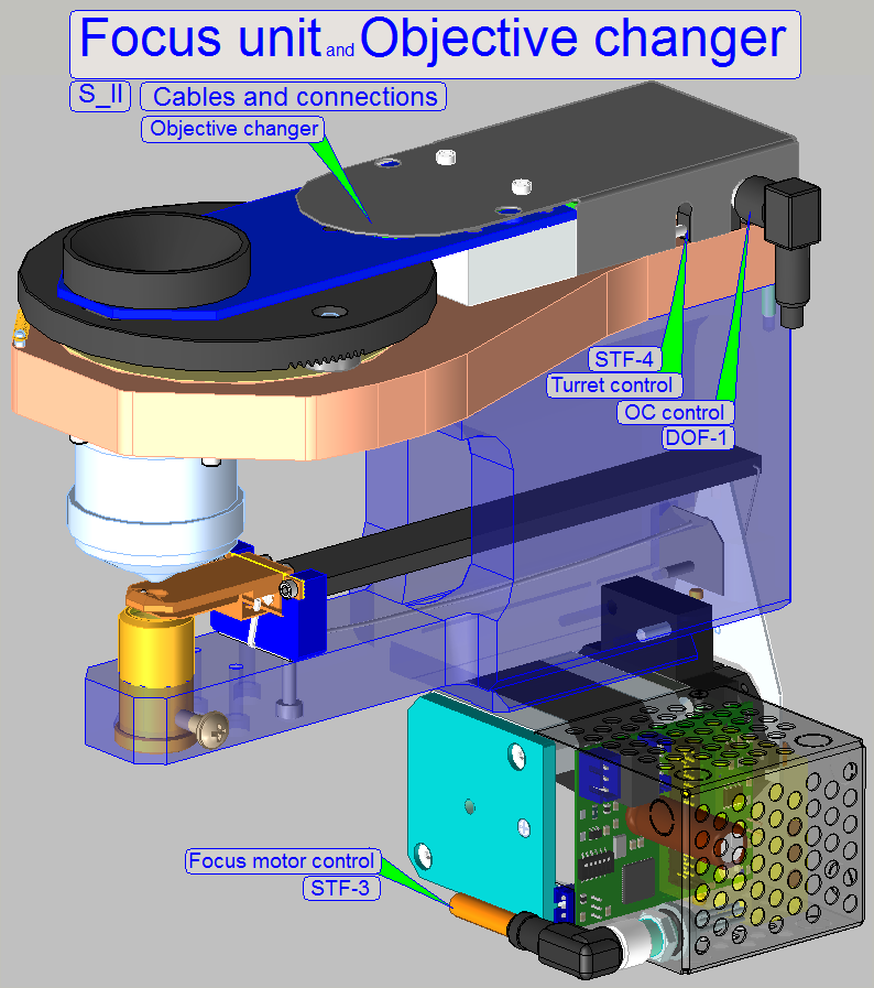
· Connect the cable DOF-1 of the SCAN to the connector
“OC control” and connect the cable STF-4 “Turret control” to the turret unit.
Features
The user is able
to use different magnifications consecutively for the brightfield and the
fluorescent scan procedure likewise,
·
Without manual objective exchange.
·
Without objective position adjustments.
·
Without additional optical and illumination
adjustments.
·
Exchange of the objective is software controlled and
possible between 2 slide scan sessions.
Once, the objective settings are defined in the dialog “Microscope
Settings” these must not be changed or modified until the objective(s) will
be exchanged physically to another type .
![]() “Objective changer”; “Configure the scanner”, “Service Program”
“Objective changer”; “Configure the scanner”, “Service Program”
Physically, the focus
position is defined by the distance of the objective to the tissue. If the
tissue is in the focus of the objective, a sharp picture is seen by the camera.
Because the tissues are different from each other in thickness and the
thickness can change inside the same tissue also, the focus position must be
checked and corrected always, during scanning.
Furthermore, if the slide
will be changed, the specimen
holder must be moved away from the objective to avoid collision.
If the shutter is changed
from shutter off to shutter on, the specimen holder is moved to a position
where the focus pin is not in connection with the specimen holder.
During all these actions,
except focusing, the objective must be protected against touching and the focus
pin as well as the 4:1 divider must be protected against overstraining. This is
realized by the focus unit, with the different positions of the focus pin and
the positions of the specimen holder; mounted on the X-Y-stage.
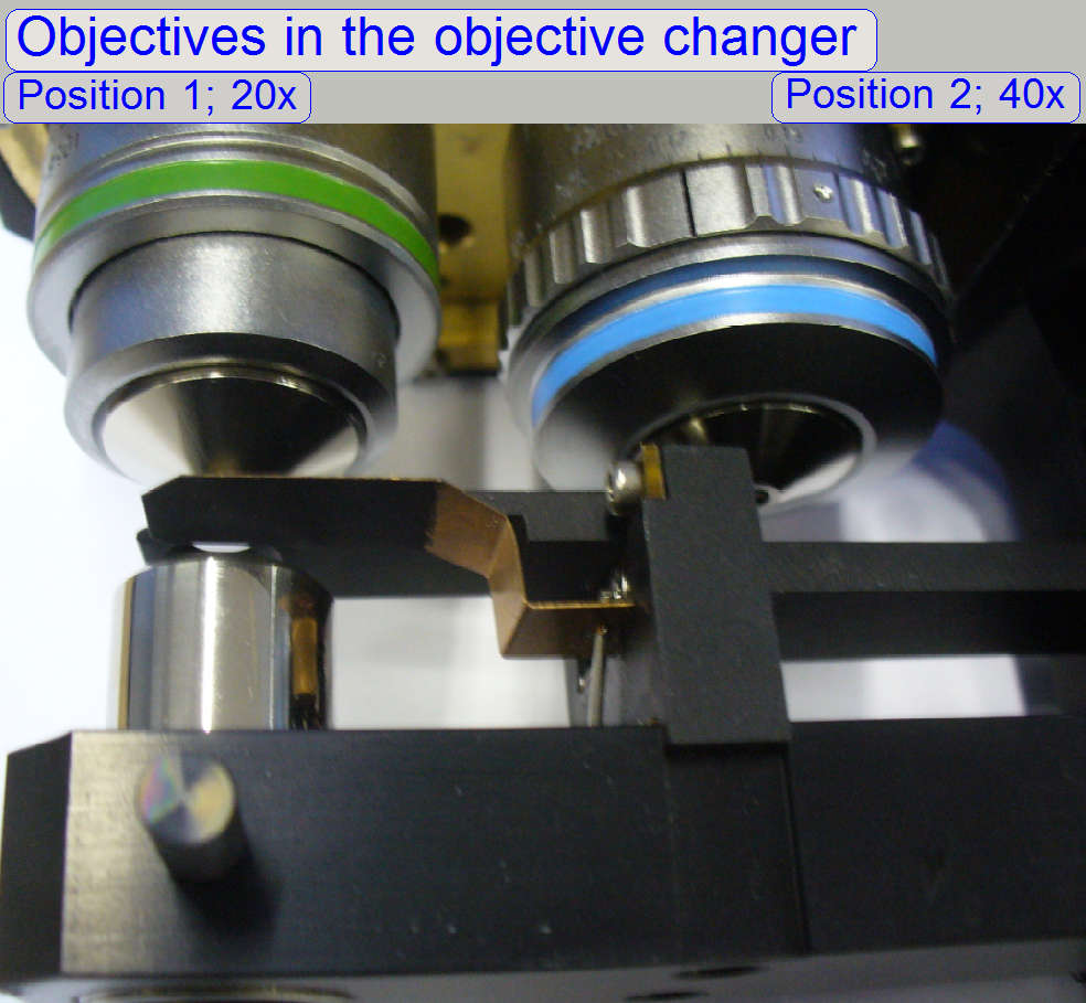
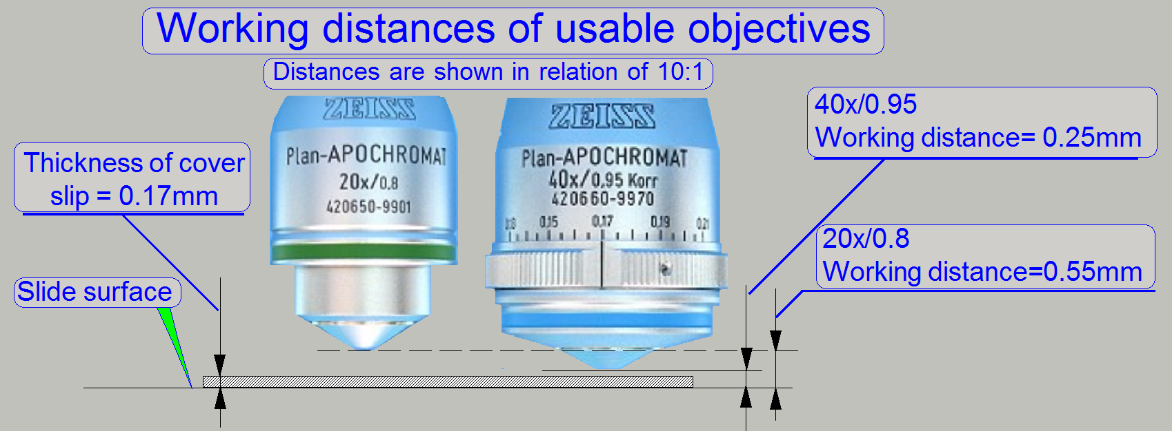 As you can see,
the gaps between cover slip and objective are very small, especially if the
objective Plan-APOCHROMAT
40x/0.95 is used.
As you can see,
the gaps between cover slip and objective are very small, especially if the
objective Plan-APOCHROMAT
40x/0.95 is used.
The worst case for focusing
is defined by the parameters of the 40x objective.
Because the objective in
Pannoramic type scanners is mounted in the nominal focus position, we have to
move the tissue toward the objective or away from it to find the real focus. It
is very important, that the objective position is adjusted well; otherwise, if
the objective focus position does not match the focus range, offered by the
focus pin movement range, a sharp camera image can never be produced.
![]() Carl Zeiss GmbH: Plan-APOCHROMAT
20x/0.8 and Plan-APOCHROMAT
40x/0.95
Carl Zeiss GmbH: Plan-APOCHROMAT
20x/0.8 and Plan-APOCHROMAT
40x/0.95
“Objectives from Carl Zeiss” Product information, stored
 On the scale of
the 40x objective, the nominal thickness of the cover slip should be selected.
On the scale of
the 40x objective, the nominal thickness of the cover slip should be selected.
- If the real thickness of the cover slip
differs from the selected value, the quality of the scanned FOV may be
reduced!
In Pannoramic type scanners
the objective is mounted into the middle of the focus range, offered by the
movement limits of the focus pin during focusing.
- Because in SCAN_II type scanners the
objective position is defined by use of fitting rings, the objective
position adjustment is not longer required; the correct objective position
is defined during mounting the objectives.
The slide is hold in the
specimen holder. To achieve a parallel movement of the slide in relation to the
objective, the specimen holding mechanics contains a parallelogram. This
guarantees the position of the tissue to be always perpendicular to the optical
axis (parallel to the objective pupil). The specimen holder has a mechanical
preload, so the slide has always a connection to the focus pin during scanning.
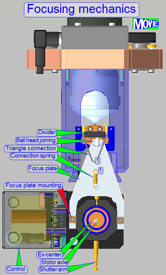
The focus pin is moved by a
stepper motor via an ex-center and an 4:1 divider. The resolution of the
stepper motor with 6400 steps per revolution, the characteristics of the
ex-center and the 4:1 divider allows a very fine resolution of the focus steps
and so tissue focusing.
Remark
The part, shown with "Compression spring" is replaced by the
"Connection spring" and the "Triangle connection".
The focus position of the FOV
is found, if the camera sees a sharp image. To reach this, the scan camera takes
images in different positions of the entire focus range and the software finds
the best focus range. When this range is found the real focus position is found
by iteration of the interval.
In opposite to the DESK,
The Home position of the entire
mechanics is situated inside the focus range. The option Home1,2 will never be
executed during normal scan operations and is used during system integration
only or before the ex-center fixing bolt
will be tightened (if mechanical adjustments are done on the ex-center). In
this case, the mounting of the ex-center starts after a Home1,2 execution. This
solution is important for protecting the 40x objective.
![]() “Specimen holders”, “Parallelogram”, “Stepper motor”
“Specimen holders”, “Parallelogram”, “Stepper motor”
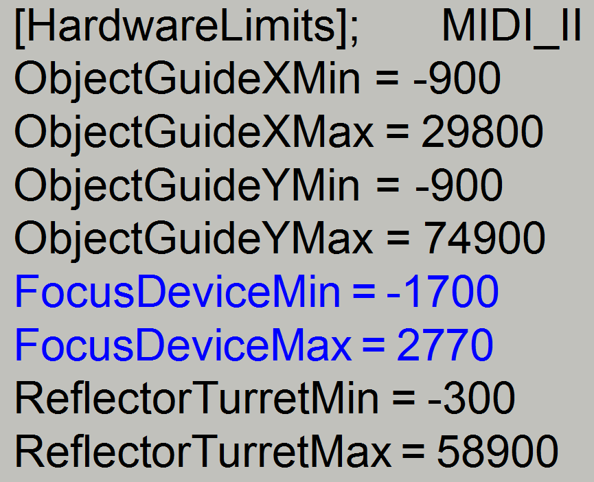
Hardware
limits; shutter on and off
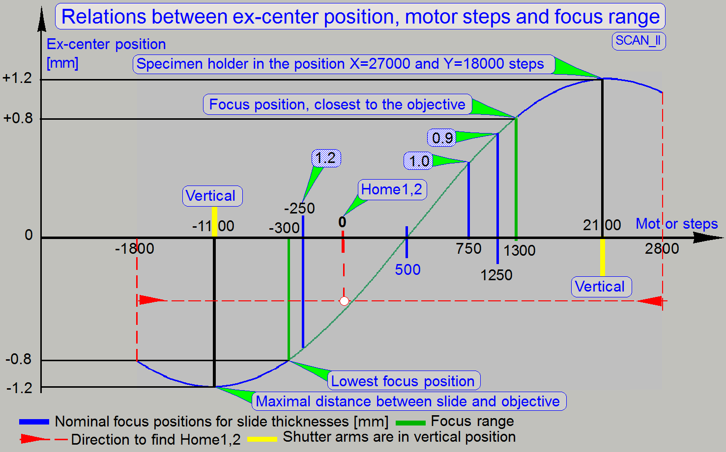
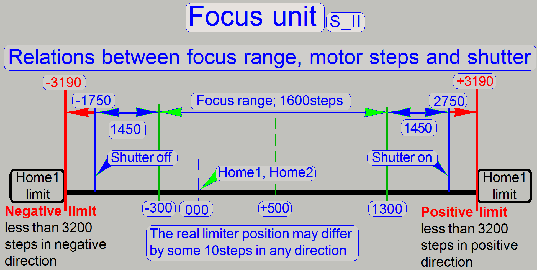 By the use of two shutter
arms, one for shutter on, the other for shutter off operation, the hardware
limits could be held inside the direction limit for Home1 (less then 3200 steps
in each direction). The hardware limits will be reached only during shutter on
(CondenserCoverOn = BF light path closed, fluoresce scan) or the shutter off
(CondenserCoverOff = BF light path opened, brightfield scan) procedure. To
prevent the touching of the 40x objective during the shutter on procedure, the
action is executed at a special specimen holder position, where the focus pin
is guaranteed between the specimen holder and the slide. This position is X=
27000 steps and Y=18000 steps. This way, the specimen holder practically does
not move, during the ex-center crosses the upper peak of the sine wave, because
there is no connection between focus pin and slide or specimen holder. Please take this into account if you are
working with the service program!!
By the use of two shutter
arms, one for shutter on, the other for shutter off operation, the hardware
limits could be held inside the direction limit for Home1 (less then 3200 steps
in each direction). The hardware limits will be reached only during shutter on
(CondenserCoverOn = BF light path closed, fluoresce scan) or the shutter off
(CondenserCoverOff = BF light path opened, brightfield scan) procedure. To
prevent the touching of the 40x objective during the shutter on procedure, the
action is executed at a special specimen holder position, where the focus pin
is guaranteed between the specimen holder and the slide. This position is X=
27000 steps and Y=18000 steps. This way, the specimen holder practically does
not move, during the ex-center crosses the upper peak of the sine wave, because
there is no connection between focus pin and slide or specimen holder. Please take this into account if you are
working with the service program!!
![]() “How to define hardware limits”
“How to define hardware limits”
In earlier developed scanner
systems (DESK,
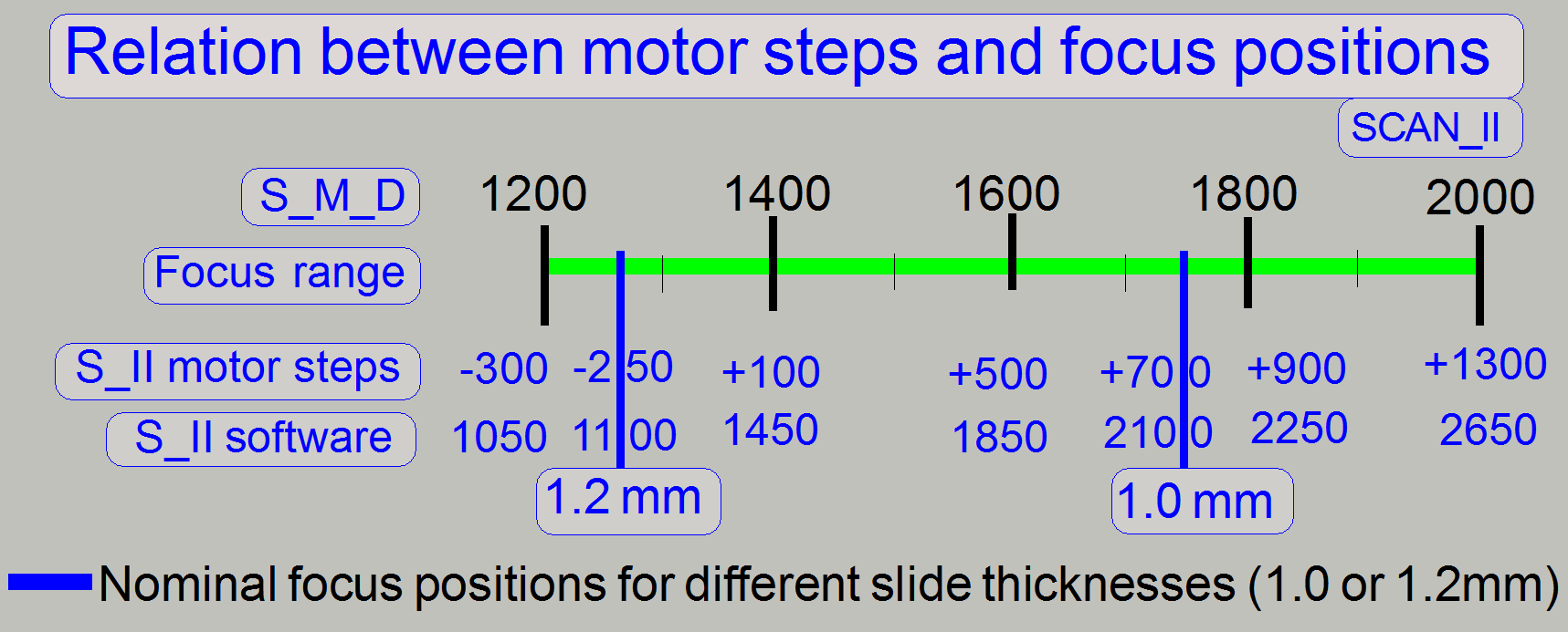
Because the resolution of the
motor is increased by twice (1 revolution of the motor axle is done in 6400
steps), the focus range is now 1600 steps, in the SCASN_II.
Because the focus range is
physically counted from -300 steps to +1300 steps, and negative numbers as
focus position are unusual, the entire focus range is shifted in the software
to the focus range from 1050 to 2650; add to the physical step number
1350.
In the Pannoramic SCAN_II: SW focus
position = HW stepper motor position + 1350.
![]() “Hardware limits and
shutter on or off”
“Hardware limits and
shutter on or off”
Because the
adjustment of the objective position is no longer required, the nominal focus
position is also constant and defined by the used objective position (inserted
fitting ring thicknesses).
![]() “Check / adjust
the objective position”
“Check / adjust
the objective position”
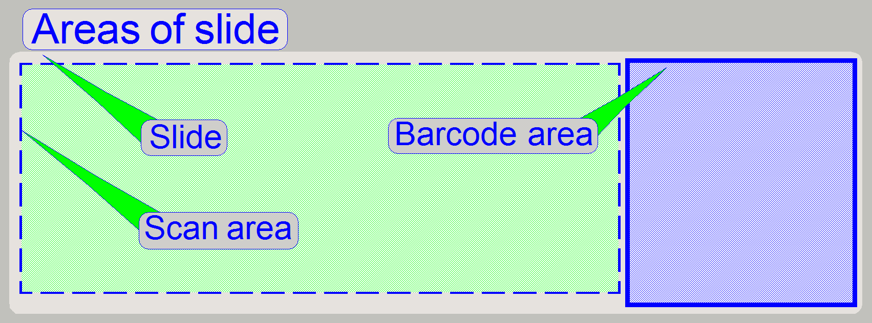
The scan area defines the part of the slide on
which the tissue, scanned by the scan camera, is expected to be. The entire
scan area is captured by the preview camera in three sections and is shown in
the preview area of the program SlideScanner.exe.
The scan area is limited by the mechanical
construction of the specimen holder and should be defined as large as possible;
it is not defined in relation to the cover slip.
In all cases, the specimen holder
should never be touched by the focus pin or the objective! In other words, the
scan area is that area of the slide, on which the focus pin and the objective
(especially 40x magnification) can be moved seemingly during scanning the
tissues, without touching the specimen holder.
Because the focus unit is equipped
with an objective changer unit, a physical objective exchange procedure is no
longer required.
Specimen holders
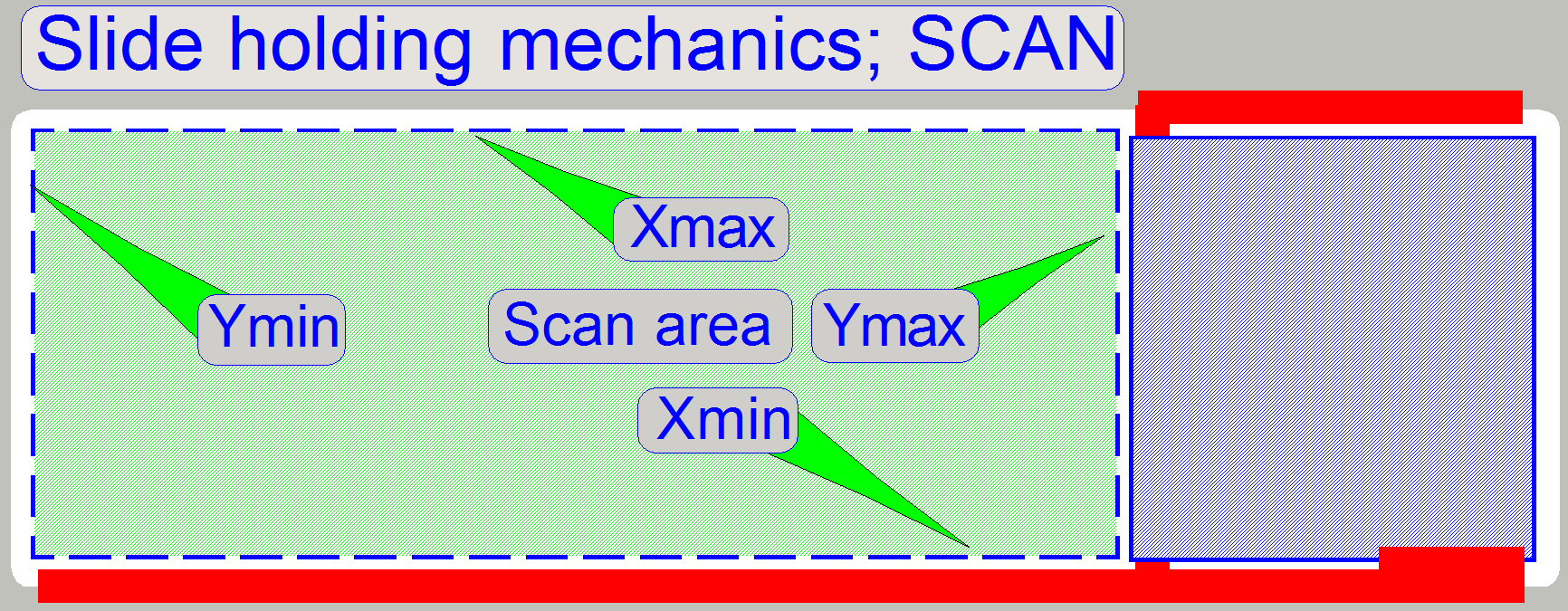
Because the physical holding of the
slide is different in all three scanner types, the scan area values are
different also and they vary from scanner to scanner of the same type also
(mechanical tolerances).
In all cases, the scan area values of X-min, X-max, Y-min and Y-max are
set just before the focus pin or the objective touches the specimen holder. The
accuracy of the limits is 100 steps.
The slide is hold by the specimen
holder on the longer, lower edge and with a slide clamp on its upper edge, on
the barcode area; see the red lines on the right. As you can see, the
definition of the limits X-min and Y-max are critical. X-max and Y-min are
given by the maximal usable slide size and are not critical; they could be the
slide edge.
![]() “Specimen holder”, “Areas of the slide”, “Scan area” and “Define the scan area”
“Specimen holder”, “Areas of the slide”, “Scan area” and “Define the scan area”
·
Since the software version 1.18 the
[Microscope]; MIDI_II
SerialNumber=PMIDI-04xxxx; Serial
number of the scanner
MicroscopeType=3DMic10; MIDI_II;
ScanCameraType= ; not
used, not defined here
PreviewCameraType=CVrmc_m8_pPro;
Preview
camera type
BarcodeReaderType=PreviewCamera; Barcode
capturing is done by the preview camera
LoaderType=SL_1Mag_12Slide_Sensor_Horizontal3; Slides are hold in the tray with 12 bays
and slide sensor used; MIDI_II
CameraChangerType=CC_None; Camera_chancher_VT
not present
ReflectorTurretType =
RT_3DH_10Pos_Belt; Belt
driven RTU present
BrightfieldLightSourceType = RGBLedLight; FOV Brightfield
illumination done by RGB BF-illumination
ObjectiveChangerType=OC_2Pos; Objective
changer type with 2 objective positions present
ObjectGuideXYZType = OGXYZ_1.2mm; The
specimen holder can hold slides with a thickness of 1.2mm maximal
FlashUnitType=NoFlashUnit Flash
illumination unit not present
NDFilterType=ND_None; ND
filter unit not present
PreviewLightType=PreviewLightUnitType_Type3; Preview illumination BF only
PowerSwitchBoardType=PowerSwitchBoard_None; Power distribution and switch
electronics not present
Following sections and parameters are also implemented
[Focus]NoFocusPinOnTheObjectHolderX=26000NoFocusPinOnTheObjectHolderY=18000
[ObjectiveChanger]ObjectiveChangerTimeout=7000
![]() If
If
“Handling
the *.ini files”; “Service
Program”
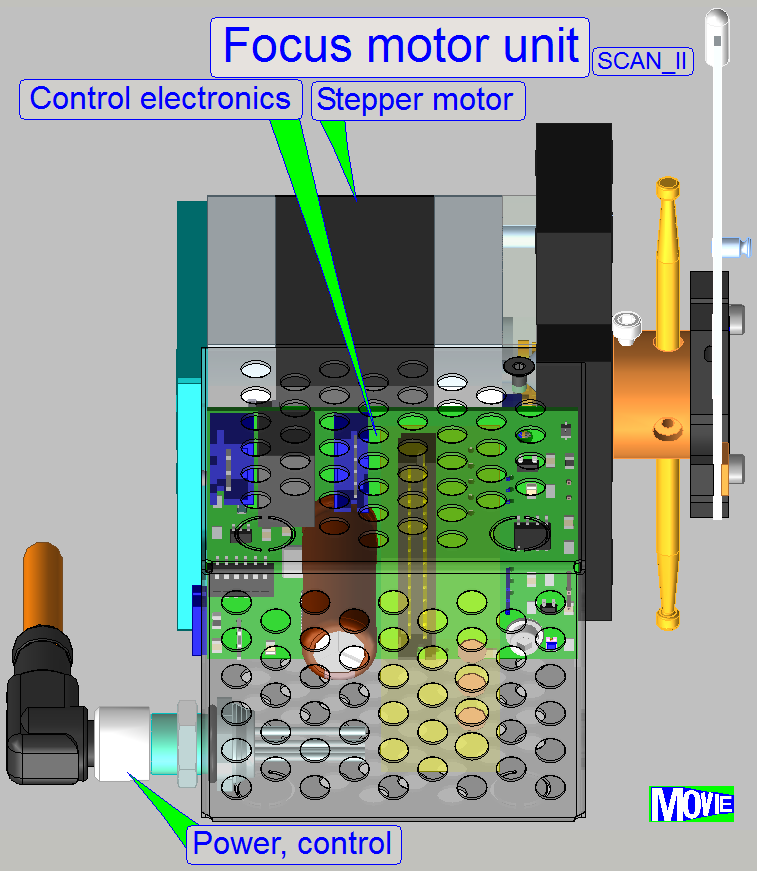
The stepper motor of the
focus unit has a resolution of 3200 steps and drives:
·
via the ex-center, the focus mechanics (see “Principle of focusing”)
and
·
via the shutter arm, the mechanical shutter (see “Principle of shutter
mechanics”).
The forward direction of the
motor’s axle is clock wise, CW (the software inverts the real direction). The
command and status relevant information for the focus unit like step number and
direction; go to Home1,2 or go to shutter on or shutter off are received from
the stepper motor’s electronics via the cable STX-3 (X
stands for the actual hardware version and depends on the scanner type also).
· The address of the
focus motor in S_M_D is always 05.
· The parts and
units of the stepper motors need neither maintenance nor mechanical
adjustments.
![]() “Stepper
motor implementation”, “Addresses”,
“Cabling of
addressable units” and “USB-controller
cabling”
“Stepper
motor implementation”, “Addresses”,
“Cabling of
addressable units” and “USB-controller
cabling”
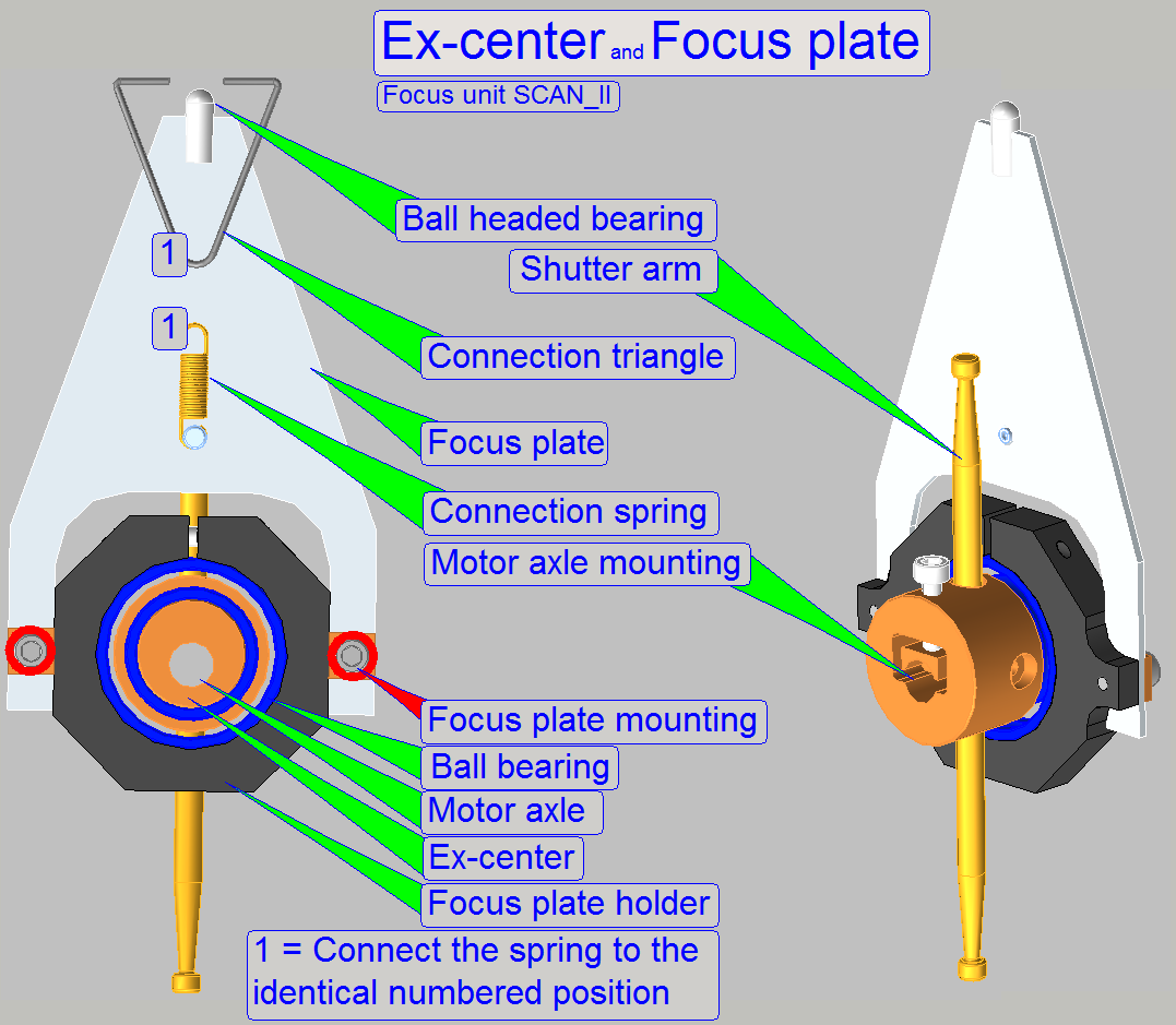
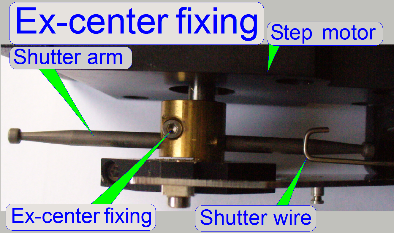
The motor axle of the stepper
motor rotates the ex-center on which the focus plate is mounted and this moves
the 4:1 divider.
·
The ex-center position is correct, if 1600 focus steps
are moved and the shutter arm stays in the middle of the slot. If this
condition is not met, please adjust the ex-center position more precise
(maximal tolerance is 10steps).
·
The bearing of the 4:1 divider and the ball-headed pin
of the focus plate eliminates the unwanted left and right movement.
Attention
The mounting bolts of the
focus plate should not be loosened; here the position of the focus plate and so
the position of the 4:1 divider and the position of the focus pin is adjusted!
Because the movement range of
the focus pin is very small, the adjustment of the focus pin position is
delicate; the focus plate mounting bolts
position must not be altered.
·
The
adjustment of the focus pin position can not be done in the field!
The connection between focus
plate and divider is realized with a ball-headed joining because the ex-center
does an up-down and additionally a left-right movement.
·
The Connection spring with the triangle connection
ensures a hysteresis-free connection.
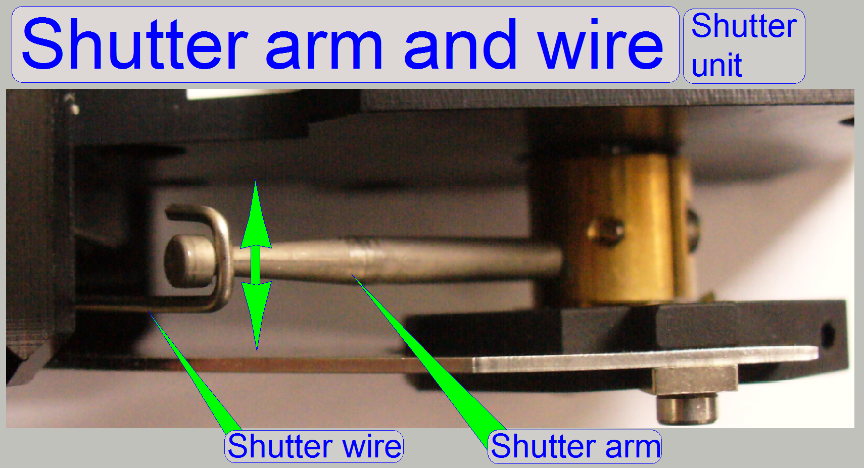
Furthermore, on the ex-center
mounting the shutter arm is situated for the shutter off and on operation and
defines so in the same time, together with the shutter wire the hardware limit
for the focus unit.
4:1 divider and focus pin
On the other end of the 4:1
divider the focus pin is realized. The focusing of the tissue is done by moving
the focus pin (and so the tissue) toward or away from the objective. Because
the focus pin touches the slide always during focusing, the distance of the
slide with tissue to the objective is modified until the focus position is
found. The mechanical construction allows a focus pin movement of 0.288mm
around the nominal focus position during focusing (focus range from 1050 –
2650steps).
The increased focus pin
movement is required, because the slide thickness is increased and may be
1.2mm.

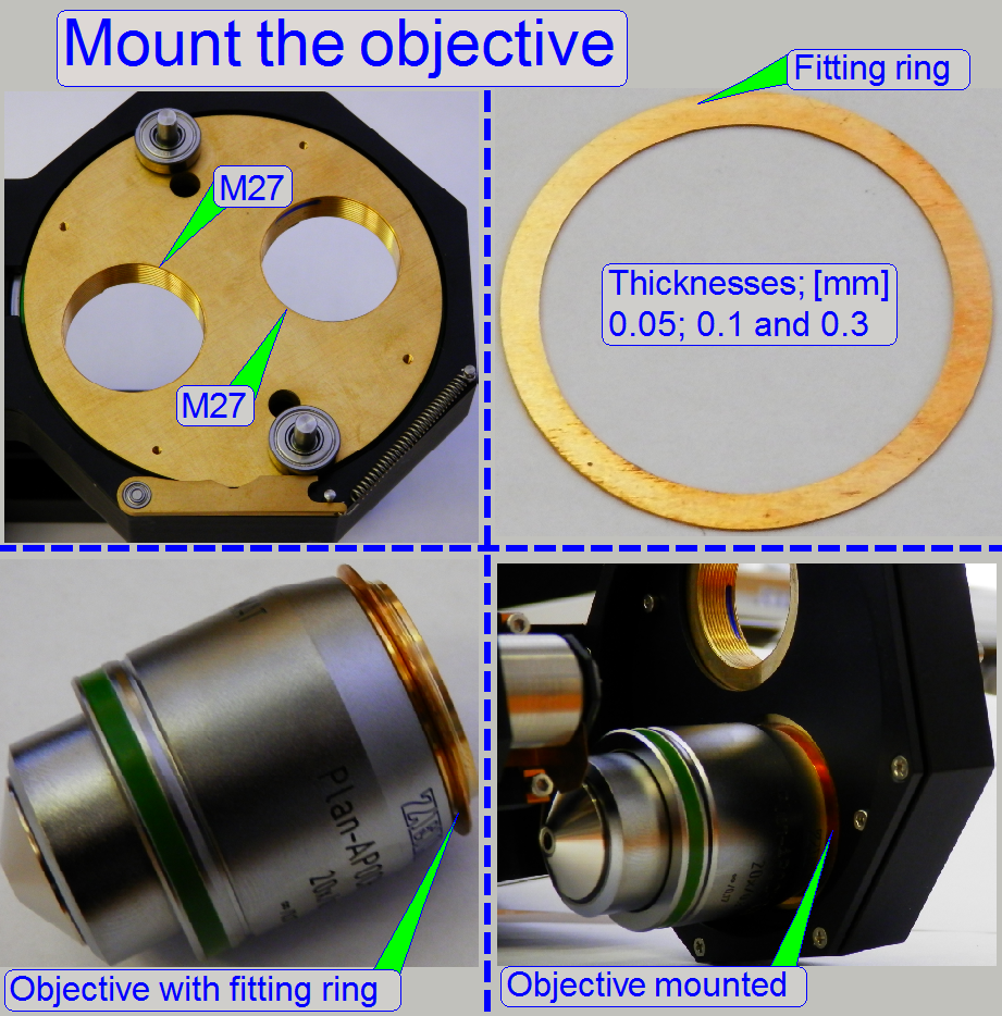
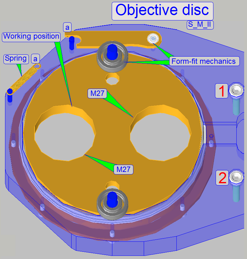
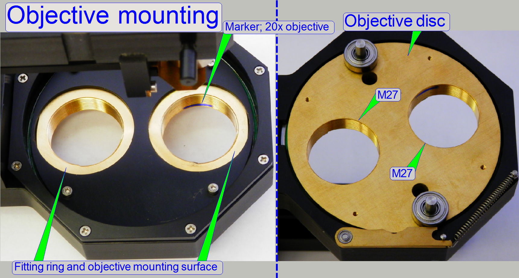
The objective disc contains 2
drillings with M27 thread, so the objective can be mounted directly.
The distance of the objective
to the focus pin (the objective position) is adjusted by using fitting rings
between the objective mounting surface and the objective disc surface.
The nominal distance is
0.3mm.
By using and combining
fitting rings of different thicknesses, the objective position can be adjusted
individual (not recommended!).
If the objective was removed,
please insert the 20x objective into the mounting with the marker again, the
objective position was adjusted with this condition.
![]() “Working distances” and “Exchange the objective SCAN,
MIDI,
DESK”
“Working distances” and “Exchange the objective SCAN,
MIDI,
DESK”
Carl Zeiss GmbH: Plan-APOCHROMAT
20x/0.8 and Plan-APOCHROMAT
40x/0.95
“Objectives from Carl Zeiss” stored PDF-file; Product information
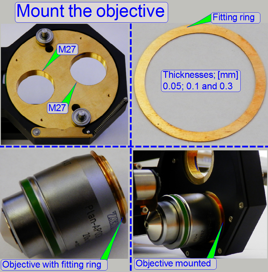
Set of objective fitting
rings
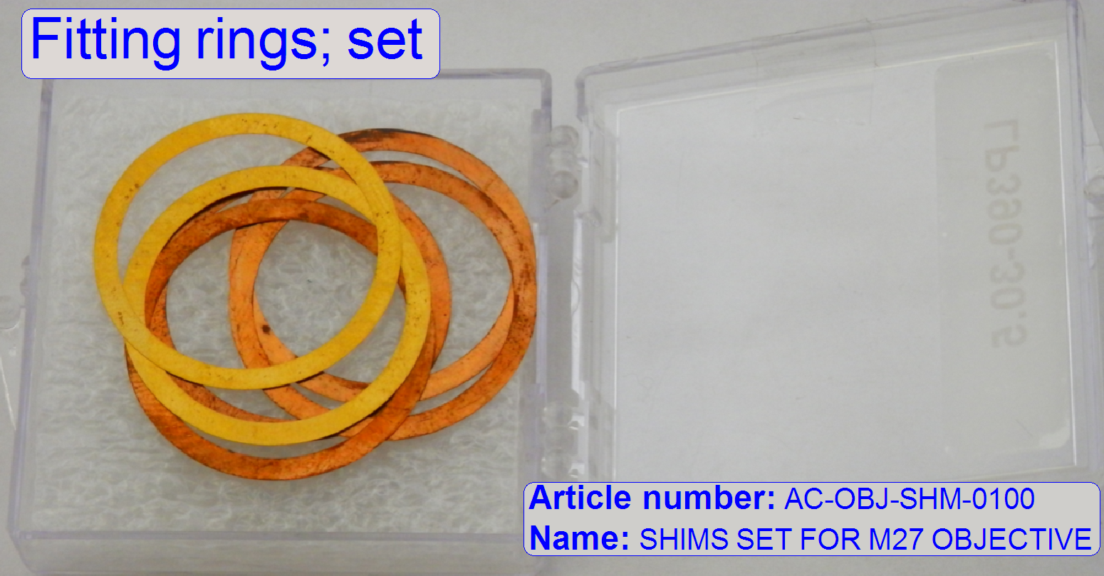 Name SHIMS
SET FOR M27 OBJECTIVE
Name SHIMS
SET FOR M27 OBJECTIVE
Article number AC-OBJ-SHM-0100
Content Nominal objective position is reached
if the thickness of the fitting ring is 0.3mm!
2x 0.3mm; already implemented
4x 0.1mm
2x 0.05mm
By using and combining
appropriate fitting ring thicknesses the distance of the objective to the
tissue can be adjusted in steps of 0.05mm.
·
Please use always the same distance of the objective
to the tissue on both objectives!
·
Because the Objective distance is already adjusted
(with the fitting rings of 0.3mm), the implemented fitting rings are not found
in the set, delivered with the scanner!
Important
Principally, the objective
position is already adjusted during the system integration process and
modification of the objective position should be done only in exceptions;
modification is strongly not
recommended!
·
If the objective(s) are dismounted, please leave the
fitting ring(s) on the objective (to avoid a mismatch)!
·
Always drive the 20x objective into the marketed
position, see above!
·
Always drive in the objective until it stops!
The focus position of both
objectives is found in the nominal focus position for the appropriate slide
thickness within a tolerance of ±50 focus steps!
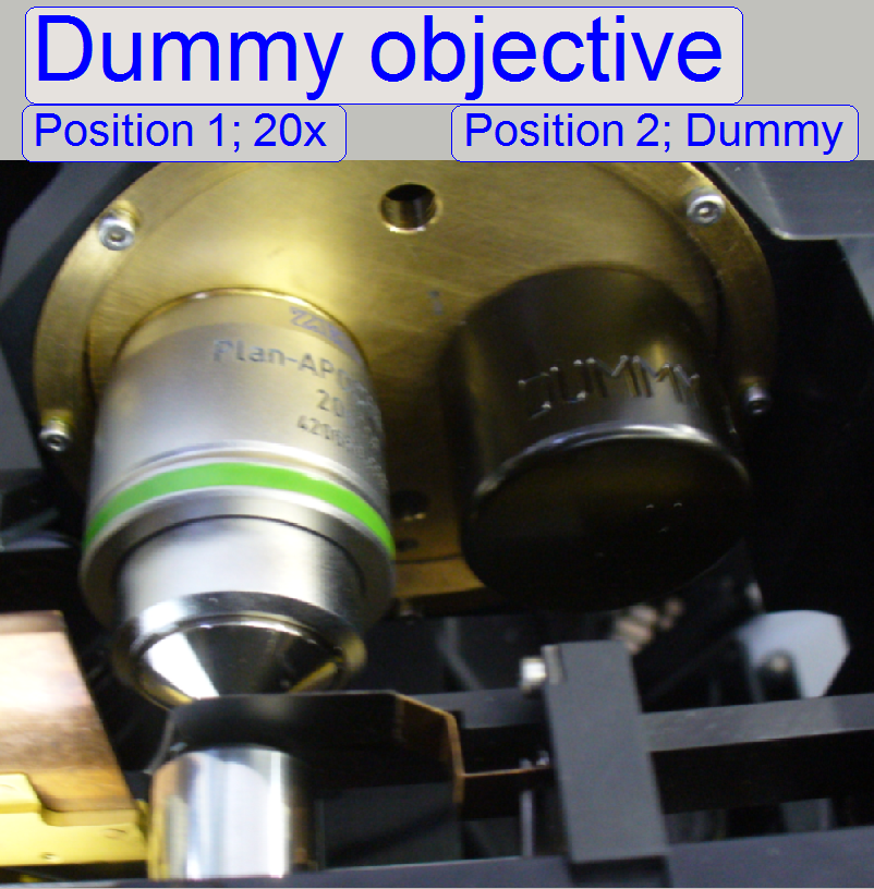
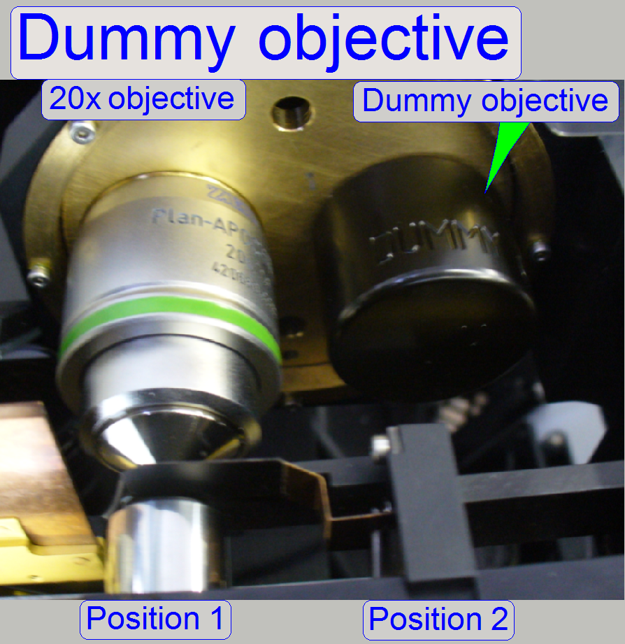
If the option 40x
magnification is not used, the dummy objective is implemented in the objective
position 2.
This way, a weight displacement
of the objective disc will be avoid; this occurs mainly in the SCAN-type
scanners.
In MIDI-type scanners this is
less important, because the objective disc is rotated horizontally.
- If a weight displacement of the objective
disc would occur, the form-fit mechanism would not work correctly and the
objective may be misaligned in the optical axis.
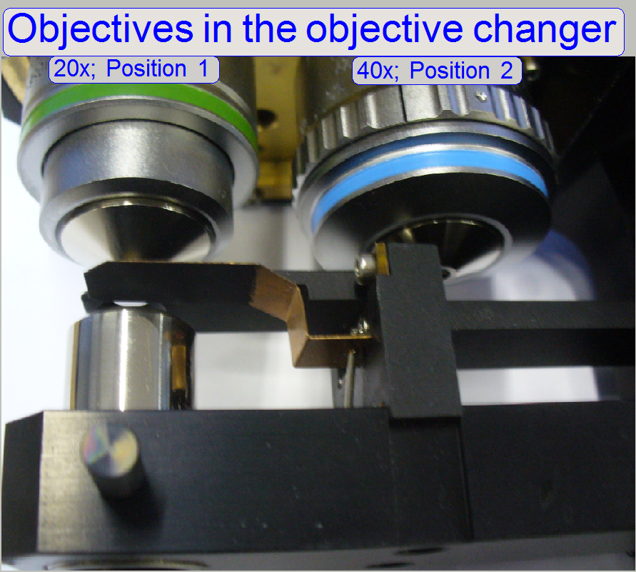
Mount the 20x objective
always into the position 1 and the 40x or dummy objective into the position 2.
- Because in all systems always a 20x objective
is used (the 40x objective is optional) the start-up procedure of the
software calibrates the system with the 20x objective.
- Furthermore, all the optical and preview
adjustments are based on the 20x objective.
- The objective positions 1 and 2 are
decided, if the drive unit will be mounted; see also “Check / Set the working
position
The software setup of
the objectives is done in the dialog “Microscope settings”, there will be
defined if the 40x objective is present or not.
![]() “Setup
objectives”; "Prerequisites
cont'd", "Camera settings"
“Setup
objectives”; "Prerequisites
cont'd", "Camera settings"
Remark
In the dialog
“Microscope settings”, any objective (20x or 40x) can be set to any position
(objective position 1 or 2), but we recommend the use of the objective 20x in
the position 1 and the 40x or dummy objective in the position 2, because some
adjustments (e.g. the
preview calibration procedure) requires the existence of the 20x objective
in the position 1.
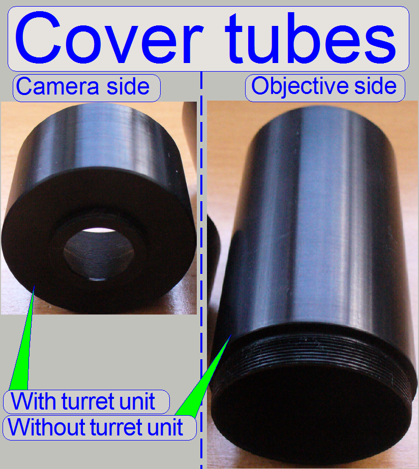
· The image path
cover tube exists in two versions; depending on the existence of the turret
unit, whether the shorter or the longer tube is used.
· The shorter cover
tube is mounted directly onto the objective nut, in opposite of the objective.
· The longer cover
tube is used if the turret unit is not implemented and is mounted into the camera tube
mounting; on the opposite side of the camera tube.
· The image path
cover tube is used in the SCAN and the
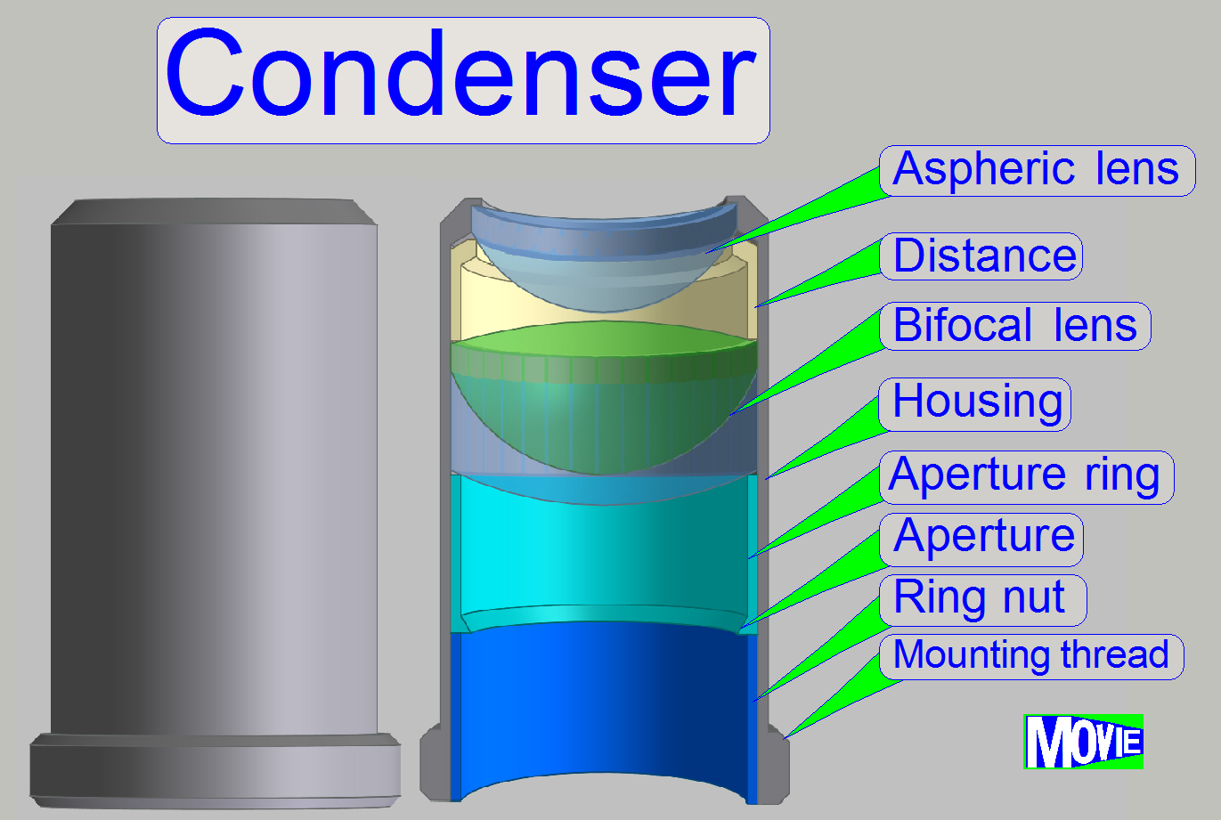
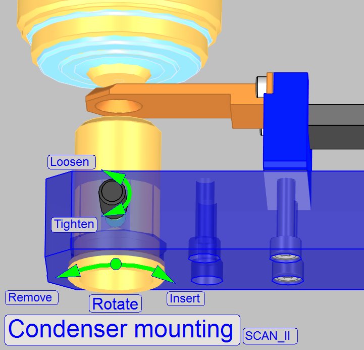
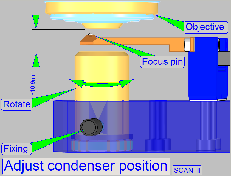
The condenser concentrates
the incoming light to the field of view (FOV).
Because the size of the illuminated part of the tissue is critical, the
condenser position can be adjusted; the focus position is 10.9mm nominal.
·
![]() Condenser Wikipedia
Condenser Wikipedia
·
condenser
position adjustment.
In the DESK and the
Important
·
Please protect the
illumination mirror by inserting a slide between scanner plate and focus unit
if the fixing bolt will be loosened or protect the condenser otherwise against
falling out.
·
In the adjusted condenser position, the condenser housing
looks only a little bit over the mounting.
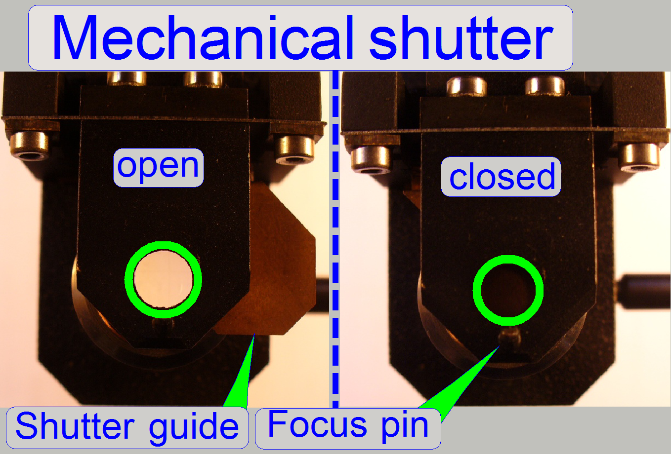
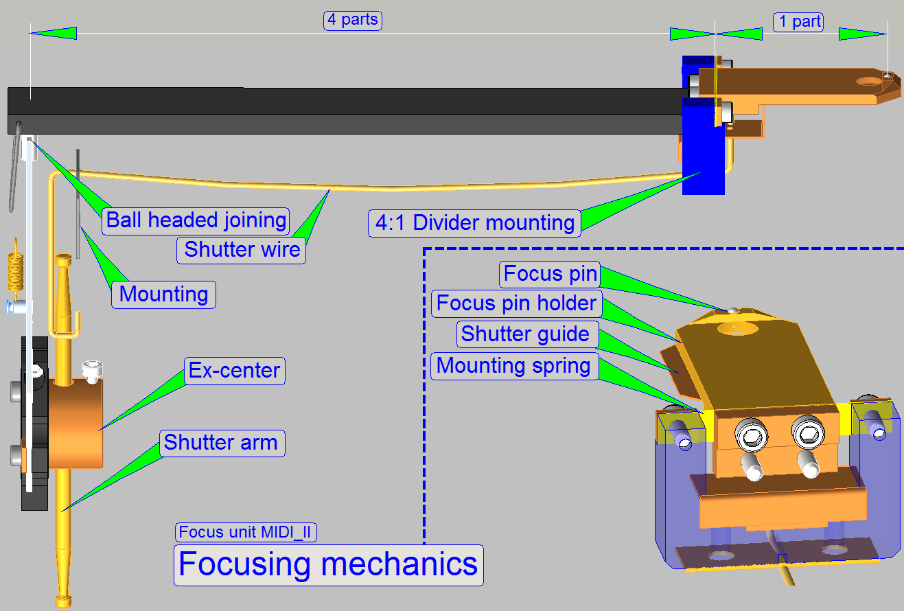
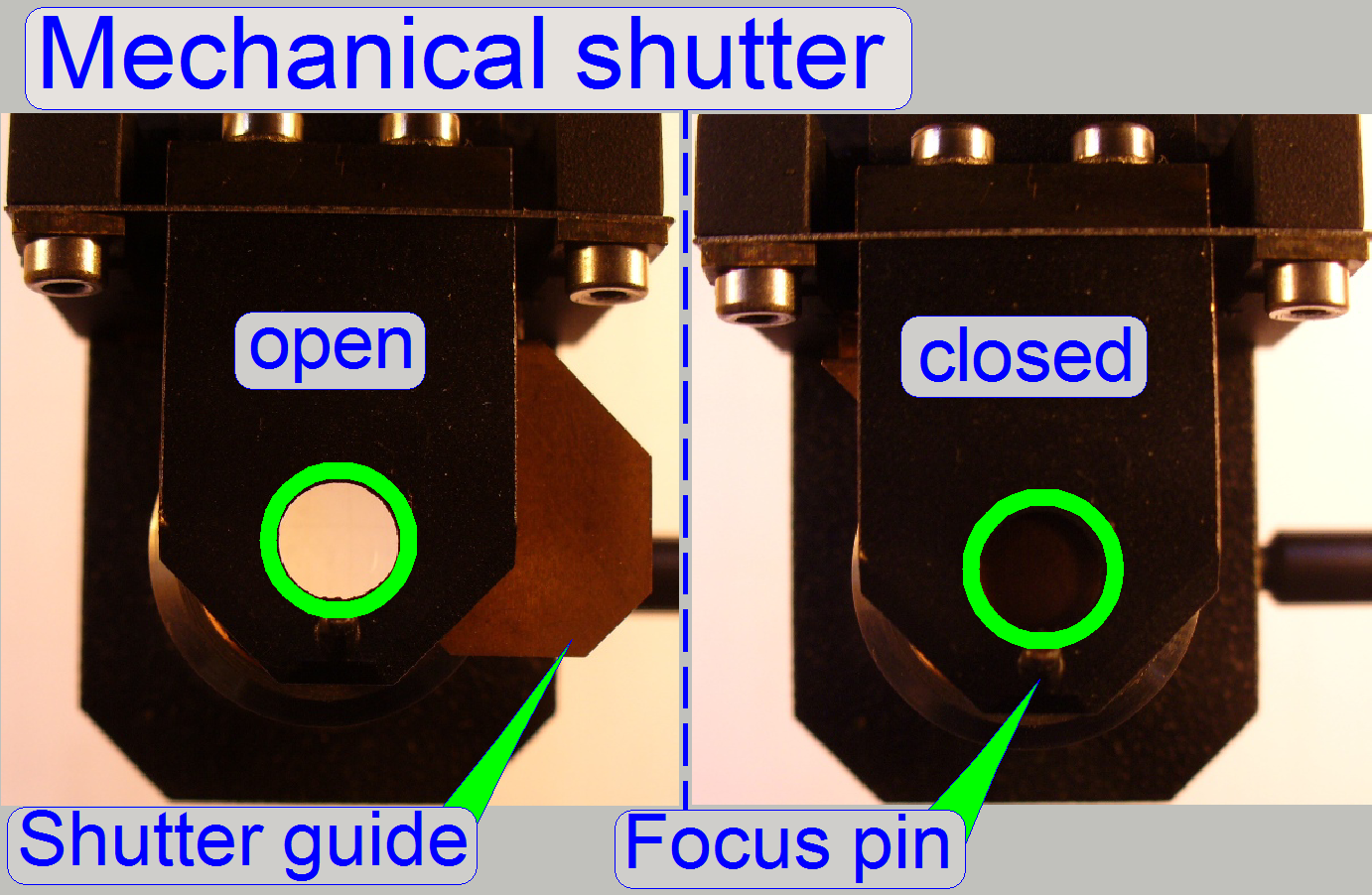
The mechanical shutter is
implemented as a part of the focus unit and the shutter guide is situated
between condenser and 4:1 divider.
During fluorescent scan the shutter
must be closed and insures so a dark background. Other, unwanted fluorescent
materials (e.g. painting, optics) can not reflect the fluorescent light or can
not fluoresce and so they will not disturb the fluorescent view.
During bright field illumination the
shutter must be fully open to ensure a bright and evenly illumination of the
FOV.
Principle of shutter mechanics
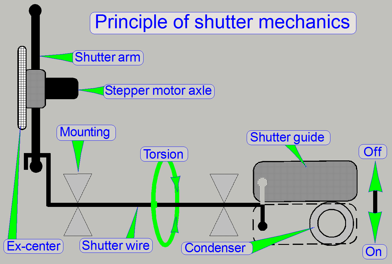
The shutter has only two usable
states, shutter on and shutter off. These positions are identical with the
hardware limits of the focus unit; in these positions the bright field
illumination (the condenser) should be fully opened or fully covered
respectively. All other possible positions of the shutter are not defined,
therefore faulty positions and not allowed during the scan process.
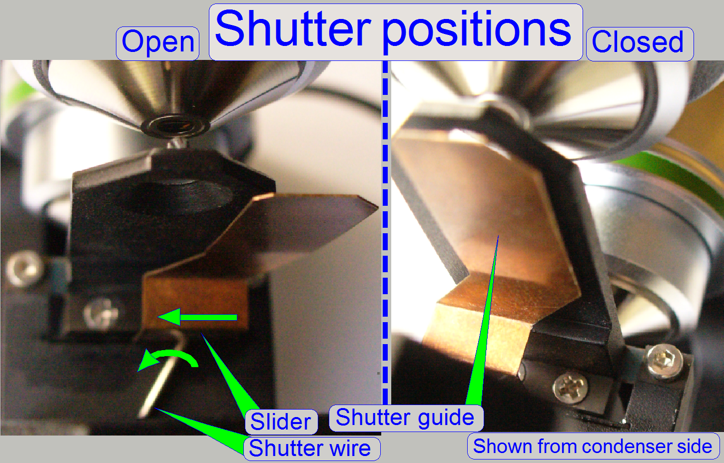
If the shutter wire is
touched by the shutter arm, the torsion is transmitted via the shutter wire to the
slider of the shutter guide. The slider brings so the shutter guide into the
proper position.
During rotation of the
stepper motor axle in direction to the negative limit of the focus unit, the
shutter wire will be touched by the shutter arm and is so moved to the shutter
off state (bright field illumination allowed). If the stepper motor axle is
rotated in direction to the positive limit, the other shutter arm will touch
the shutter wire from the opposite direction and moves so the shutter guide to
the shutter on position (bright field illumination disabled).
In practice it means, that
the shutter wire together with the shutter arms is the limiter of the focus mechanics
and with this limiter the shutter on and shutter off option is realized.
·
During focusing the shutter wire will never be touched
by the shutter arm.
The following procedures are
described especially for Pannoramic SCAN. In Pannoramic MIDI the adjustments
are logically identical, but some terms like “up, down, top, bottom, left,
right, horizontal and vertical” differ. Please take this into account if you
are adjusting the
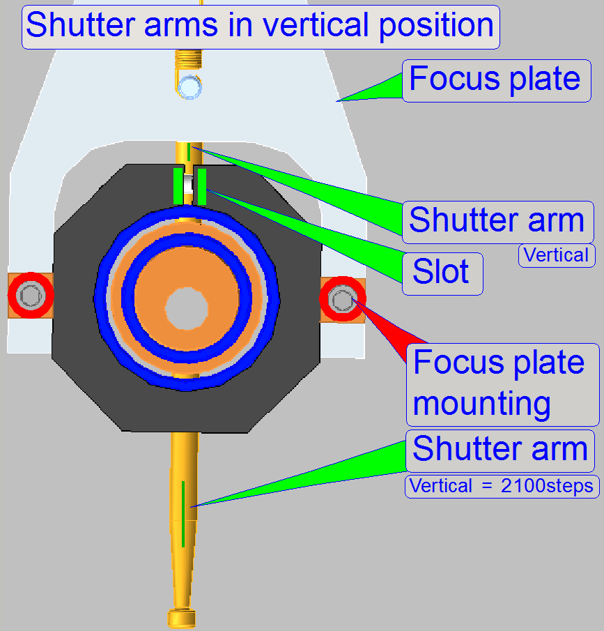
This adjustment must be done
only if the ex-center was dismounted or the fixing bolt was loosened. With this
adjustment the focus position is set to be +500steps nominal.
Because in this position the
fixing bolt can not be loosened or tightened, we use the focus stepper motor
position of 2100 steps for this adjustment.
1.
Loosen the ex-center fixing bolt so, that the
ex-center can be rotated and moved on the motor axle.
2.
With the service program set the focus unit to
Home1,2.
3.
Go forward to the focus motor position 2100 steps.
4.
Bring the ex-center into the vertical position (the
shutter arms shows up and down; use the slot of the focus plate mounting to
find the proper position. Before you are tighten the ex-center fixing bolt
please check the position of the shutter arm in relation to the shutter wire
(hook) also. The shutter arm should touch the shutter wire nearly in the middle
of the hook. To reach this, shift the ex-center in proper position on the motor
axle and tighten the fixing bolt.
Attention
A small gap between motor mounting surface and
ex-center mounting should exist, otherwise, if the ex-center mounting rubs on
the motor mounting surface, the focus unit may lost rotor movements and so the
scanned tissue may be out of focus or blurry, even if the focus rotor direction
had changed.
5.
Go to the positions Home1,2.
6.
Go forward to the focus motor position +2100steps.
7.
In this position the shutter arms should showing
exactly up and down. A deviation of max. 10 steps from the vertical direction
is allowed. If the deviation is too much, repeat the adjustment from step 1.
Find the hardware limits for
the focus unit
This procedure must be done
only if the ex-center was dismounted or its fixing bolt was loosened. Before
the following procedure is done, the previous adjustment “Adjust the ex-center position”
should be correct.
![]() “Hardware limits;
shutter on and off”
“Hardware limits;
shutter on and off”
Find the negative limit
8.
With the
service program set the focus unit to Home1,2.
9.
Go forward to the focus motor position -1750 steps.
10.
Go backward +1750 steps.
11.
Press Home1 (only). There should be not more then +-2
steps difference to Home1.
If there are more steps
lost, decrease the actual number of steps by 10 and repeat from step
12.
If there are not more then 2 steps difference to
Home1, increase the number of steps by 10 and repeat from step
13.
The negative limit is found correctly if the motor
movement has no steps lost and the actual number of steps, increased by 10
would produce lost steps.
The found negative
limit can differ by more ten steps from unit to unit. The reasons are the
tolerances of the components and the used position of the ex-center in relation
to the motor axle.
14.
Update the parameter value of the parameter
“FocusDeviceMin” with the found number of the actual steps in the file “MicroscopeConfiguration.ini”
section [HardwareLimits].
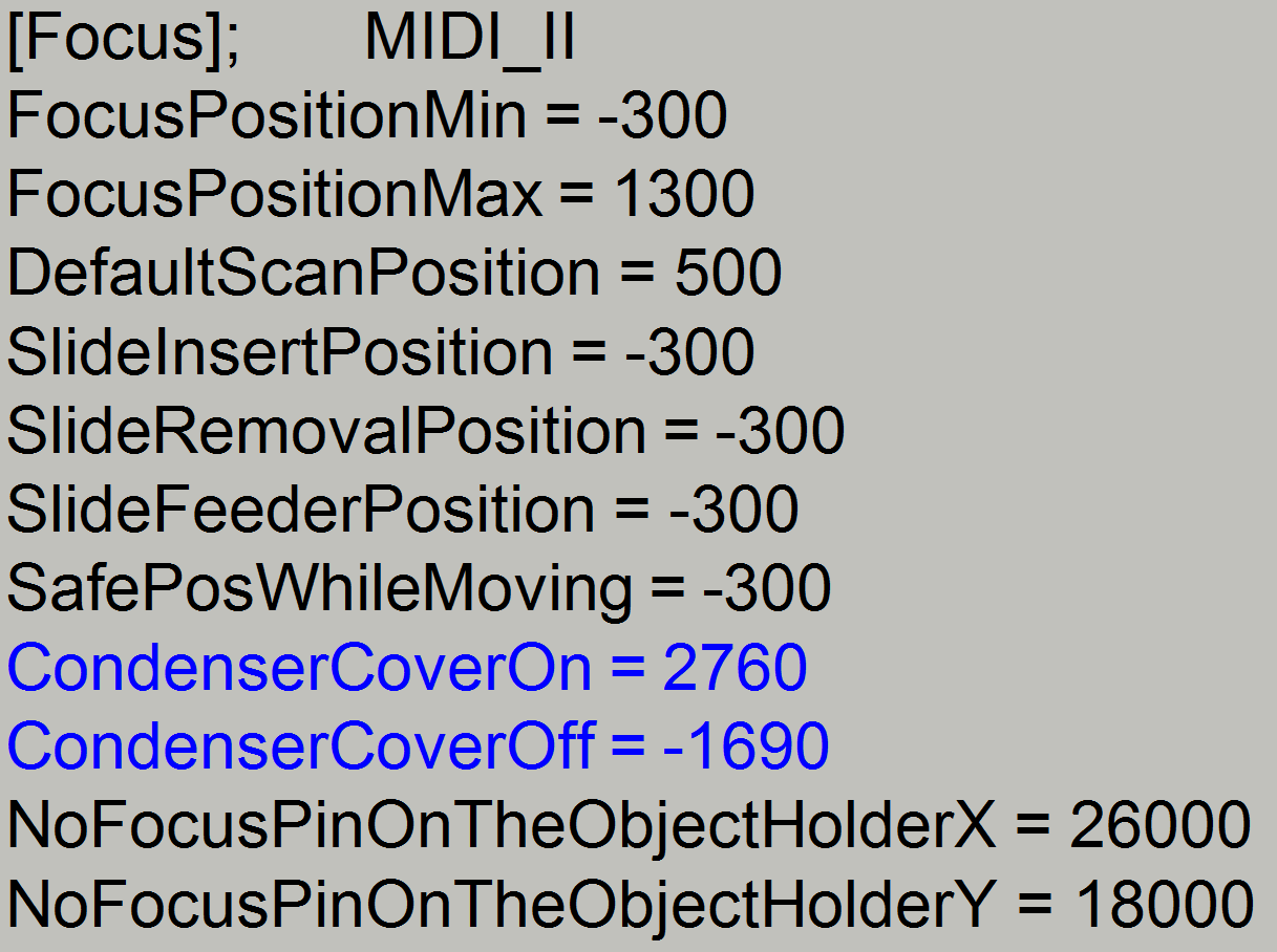
15.
Update the
parameter value of the parameter “CondenserCoverOff” with the found value in
the file “MicroscopeConfiguration.ini” section [Focus].
 Find the positive limit
16.
With the service program set the focus unit to
Home1,2.
17.
Go forward to the focus motor position +2750 steps.
18.
Go backward 2750 steps.
19.
Press Home1 (only). There should be not more then +-2
steps difference to Home1.
If there are more
steps lost, decrease the actual number of steps by 10 and repeat from step
20.
If there are not more then 2 steps difference to
Home1, increase the number of steps by 10 and repeat from step
21.
The positive
limit is found correctly if the motor movement has no steps lost and the actual
number of steps, increased by 10 would produce lost steps.
The found positive
limit can differ by more ten steps from unit to unit. The reasons are the
tolerances of the components and the used position of the ex-center in relation
to the motor axle.
22.
Update the
parameter value of the parameter “FocusDeviceMax” with the found value in the
file “MicroscopeConfiguration.ini” section [HardwareLimits].
23.
Update the
parameter value of the parameter “CondenserCoverOn” with the found value in the
file “MicroscopeConfiguration.ini” section [Focus].
Dismount; mount
the focus unit
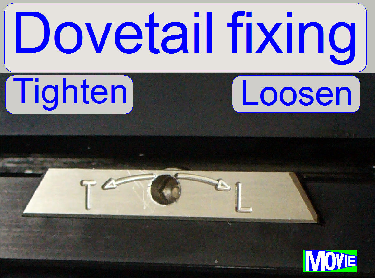
The mounting of the focus
unit with objective changer is realized with dovetail; the unit is hold by a
dovetail fixing clamp.
- Rotate the screw driver clockwise to open
(loosen) the dovetail clamp.
- Make sure, that the
X-Y-Stage is not in the X-home position, because in this position the
focus unit can not be removed.
1.
With the service program go forward to the position
10,000 steps in +X direction (3 revolutions of the motor axle).
2.
Disconnect the bus cables DOG-1 of the objective
changer and STG-4 of the turret stepper motor.
3.
Disconnect the cable of the focus motor.
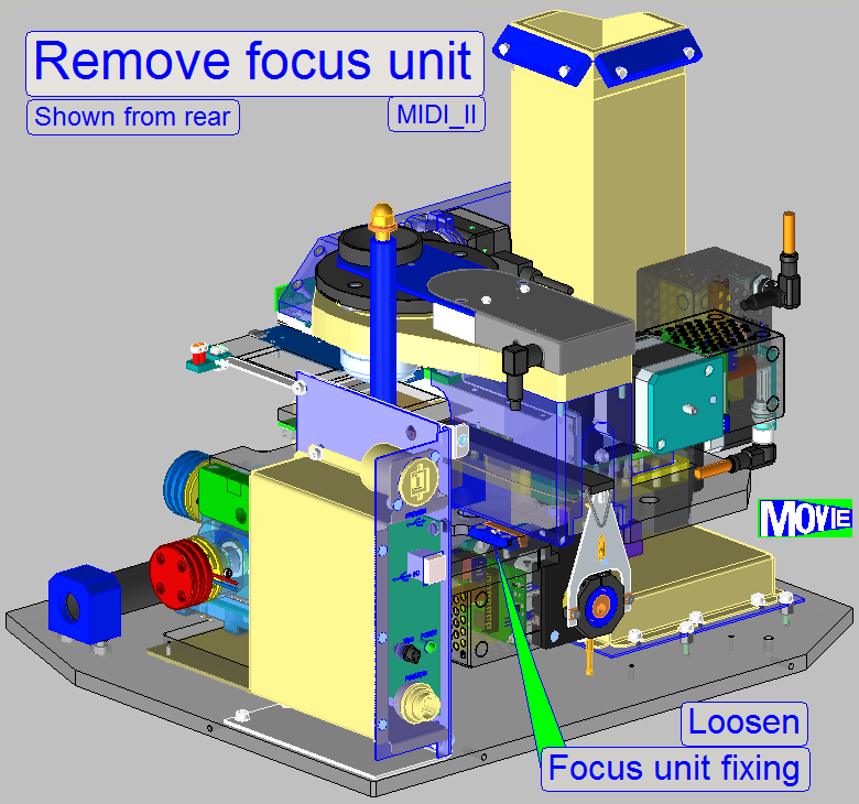
4.
Loosen the fixing
bolt of the focus unit mounting; turn the screw driver clockwise!
5.
Remove the entire focus and objective changer unit by
pulling the unit backward.
Watch Video: Remove focus unit (S_II)
Remark
The focus unit can be removed
without removing other units!
6.
Insert the focus unit with objective changer into the
dove tail of the scanner plate until the physical limit is reached; take care
on the objectives.
7.
Tighten the fixing bolt of the focus unit mounting;
turn the screw driver counter clockwise!
8.
Connect the bus cables DOG-1 of the objective changer
and STG-4 of the turret stepper motor.
9.
Connect the cable of the focus motor.
Watch Video: Mount focus unit (S_II)
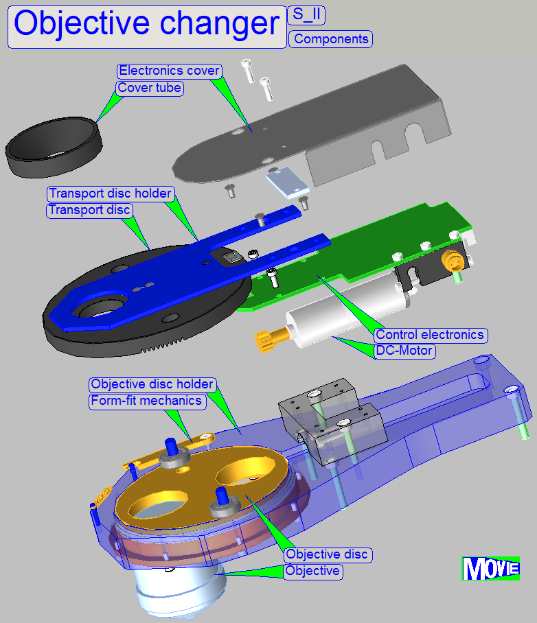
The objective changer part of
the focus unit consists of:
- The
drive unit with the transport disc, the DC motor and the control
electronics.
- The electronics cover and
- The objective changer mechanics with the objective disc, the form-fit mechanism and the objective holding
drillings.
Important
The drive unit can be
separated from the objective changer mechanics unhesitatingly, but do not remove the objective changer
mechanics from the focus part; see “Align the
objective into the optical axis” first!
Watch Video: Objective changer; assembling
Functional overview and
construction
The following chapters,
concerning the objective changer are true for the “
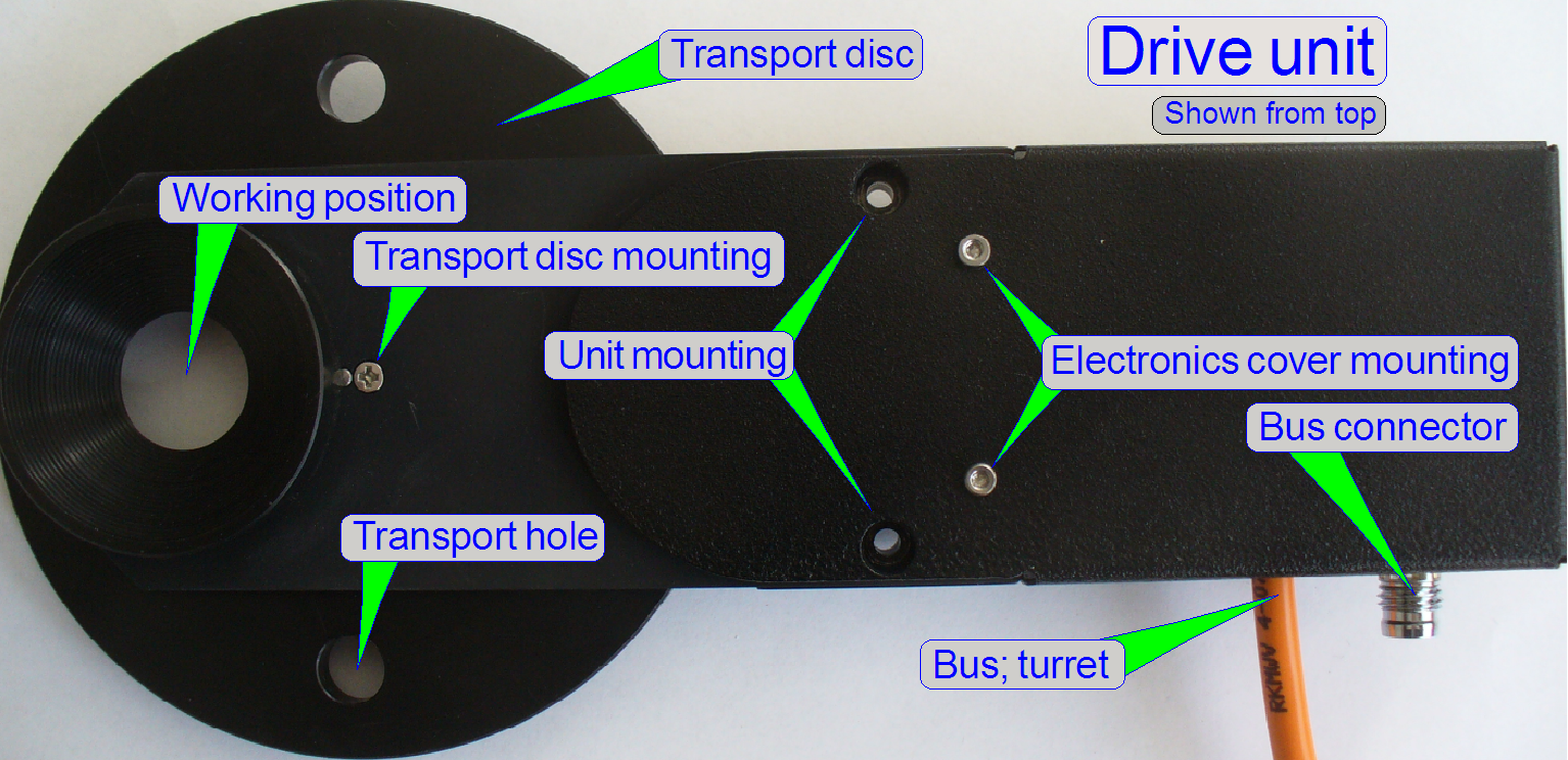 Drive
unit (from top)
Drive
unit (from top)
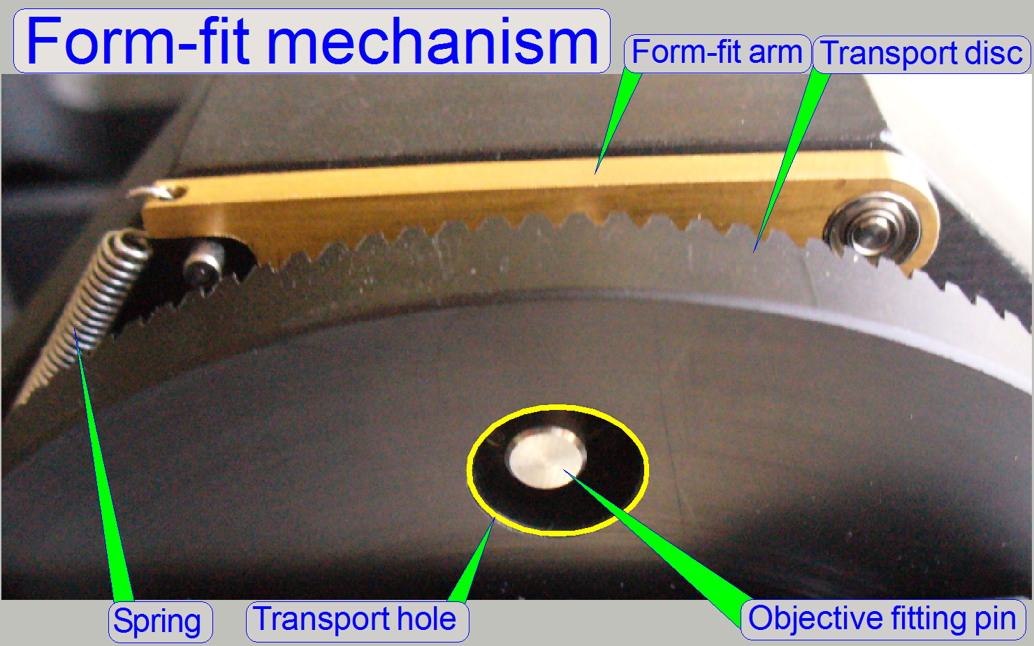
The transport disc is rotated
by the DC motor; always in the mathematical positive direction, if we are looking
onto the objectives (during normal work).
The transport disc moves the
transport pins situated in the transport holes, by a half revolution.
Just before the working
position of the objective is reached, the DC motor will be switched off by the
appropriate sensor and the final movement, into the exact working position
(into the optical axis), is done by the form-fit mechanism.
- The transport disc can be rotated manually,
but do it carefully!
- The unit does not need maintenance or
adjustments.
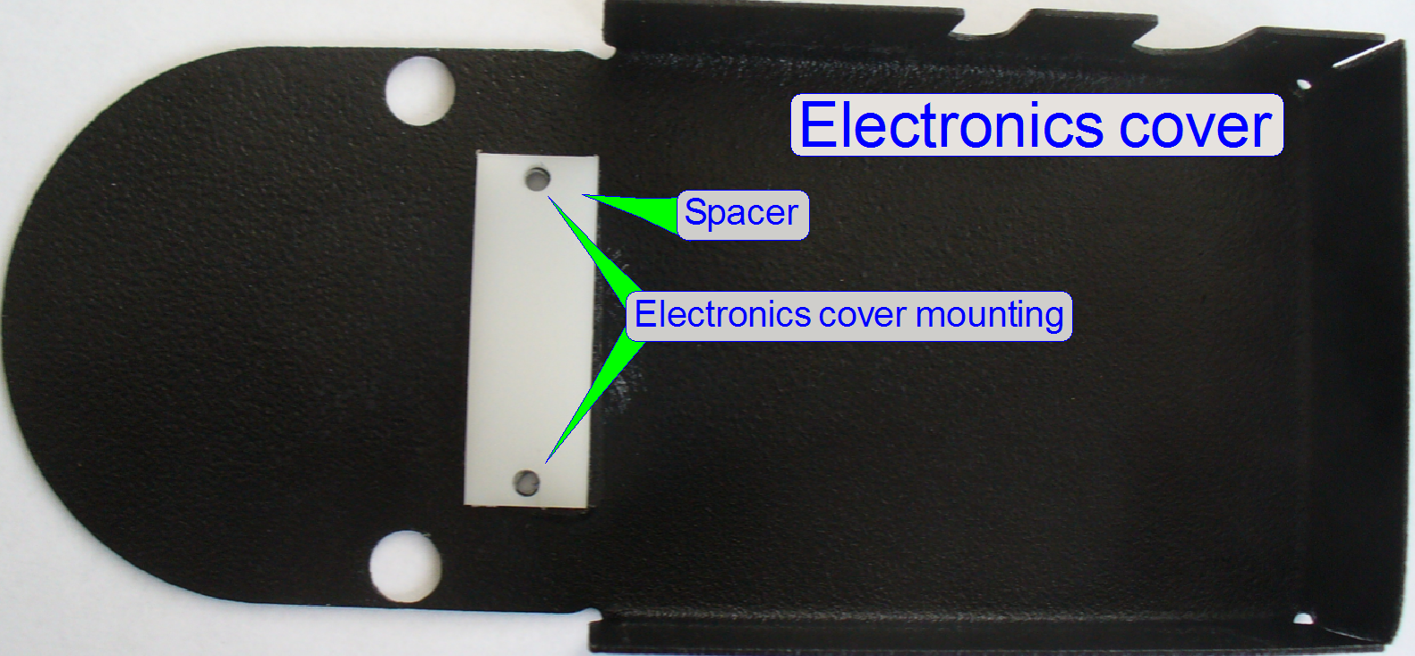
The spacer in the electronics
cover keeps a distance between cover and PCB and avoids so a shortcut in the
electronics.
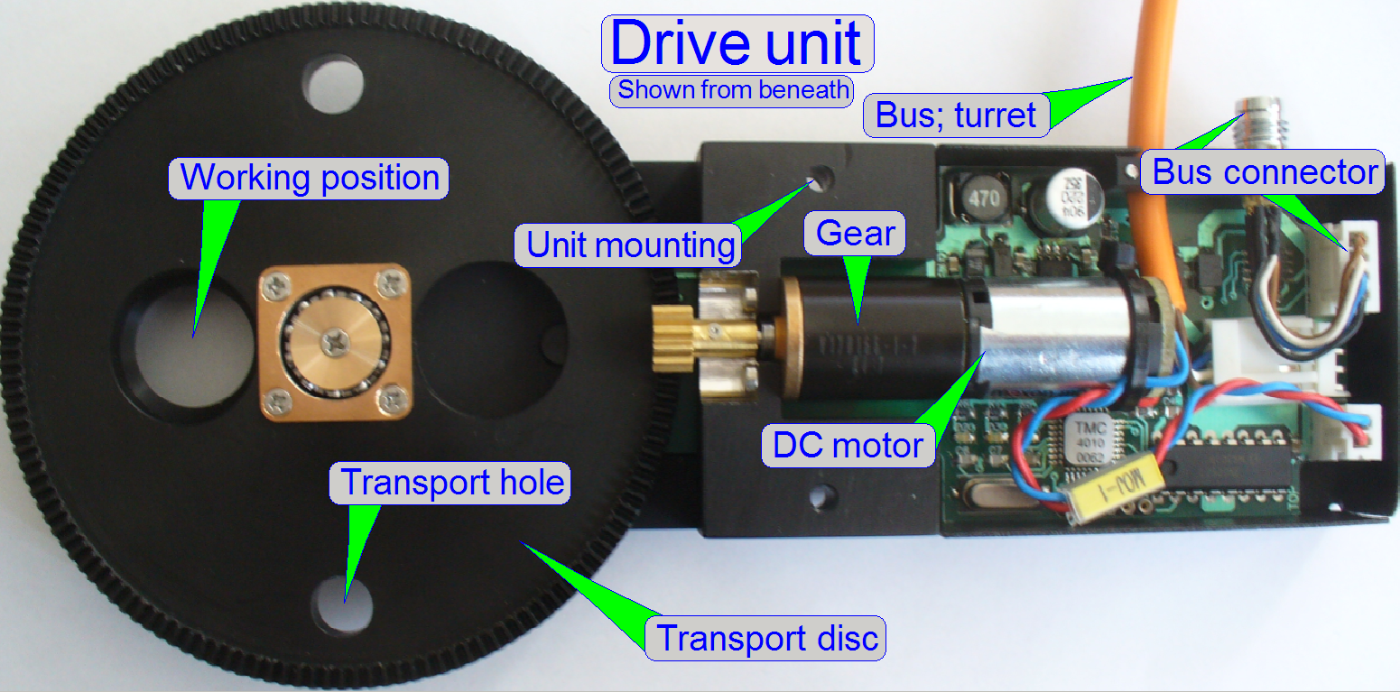
- The control electronics get its
information via the cable
DOF-1 and the bus connector; the bus is prolonged to the turret unit
via the cable STF-4.
- The address of the
control electronics is 09.
- The objective
changer type is defined in the file
“MicroscopeConfiguration.ini” in the section:
[Microscope]
.
.
.
ObjectiveChangerType=OC_2Pos
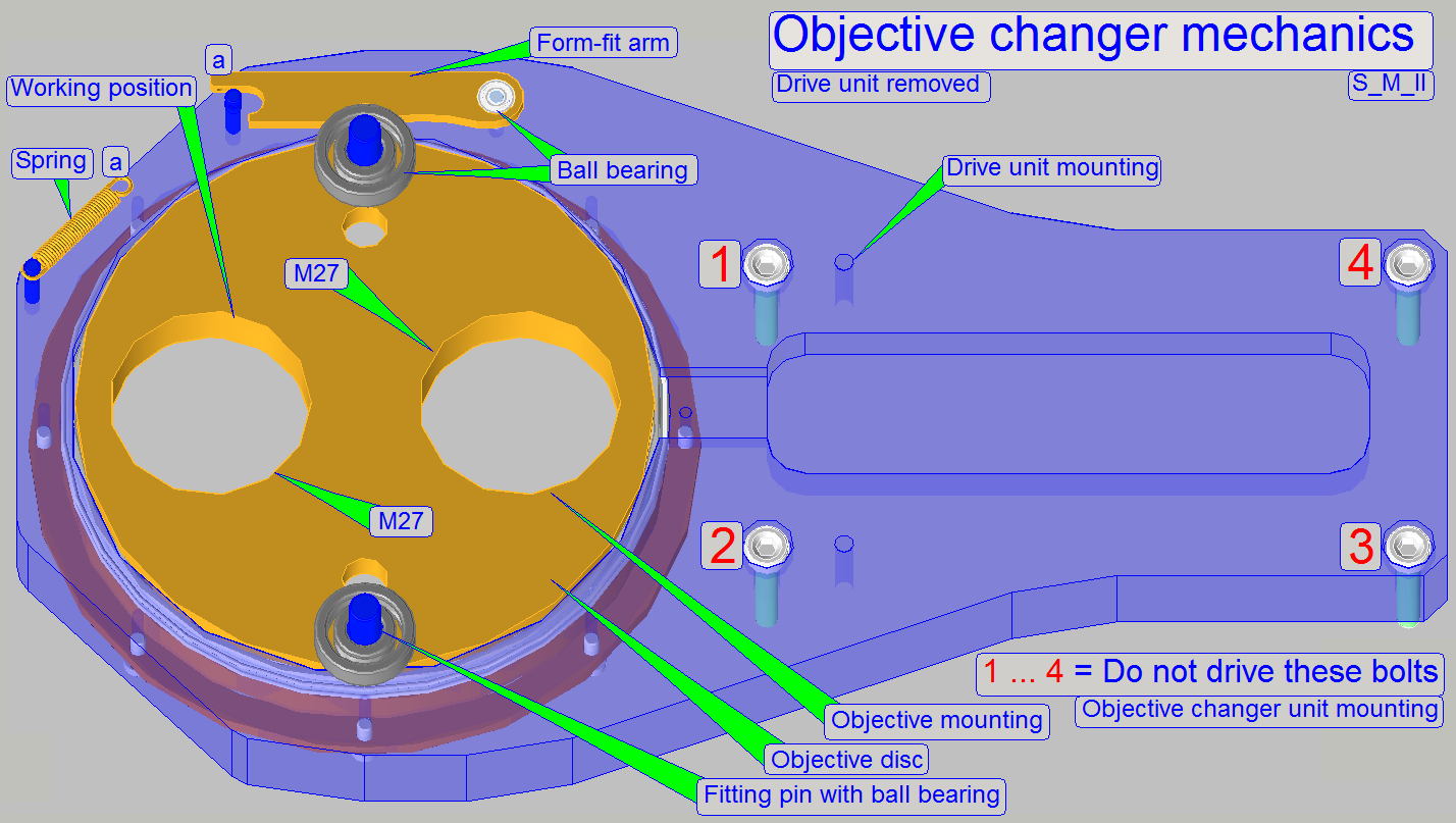
- The objective disc holds the
objectives and is driven by the fitting pins.
- The form-fit arm, together
with the ball bearing of the fitting pin guarantees the proper and
constant objective position in the light path, even if the objective has
been exchanged.
- The objective
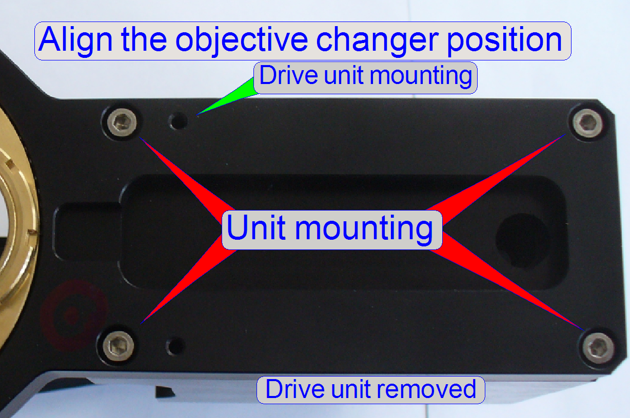
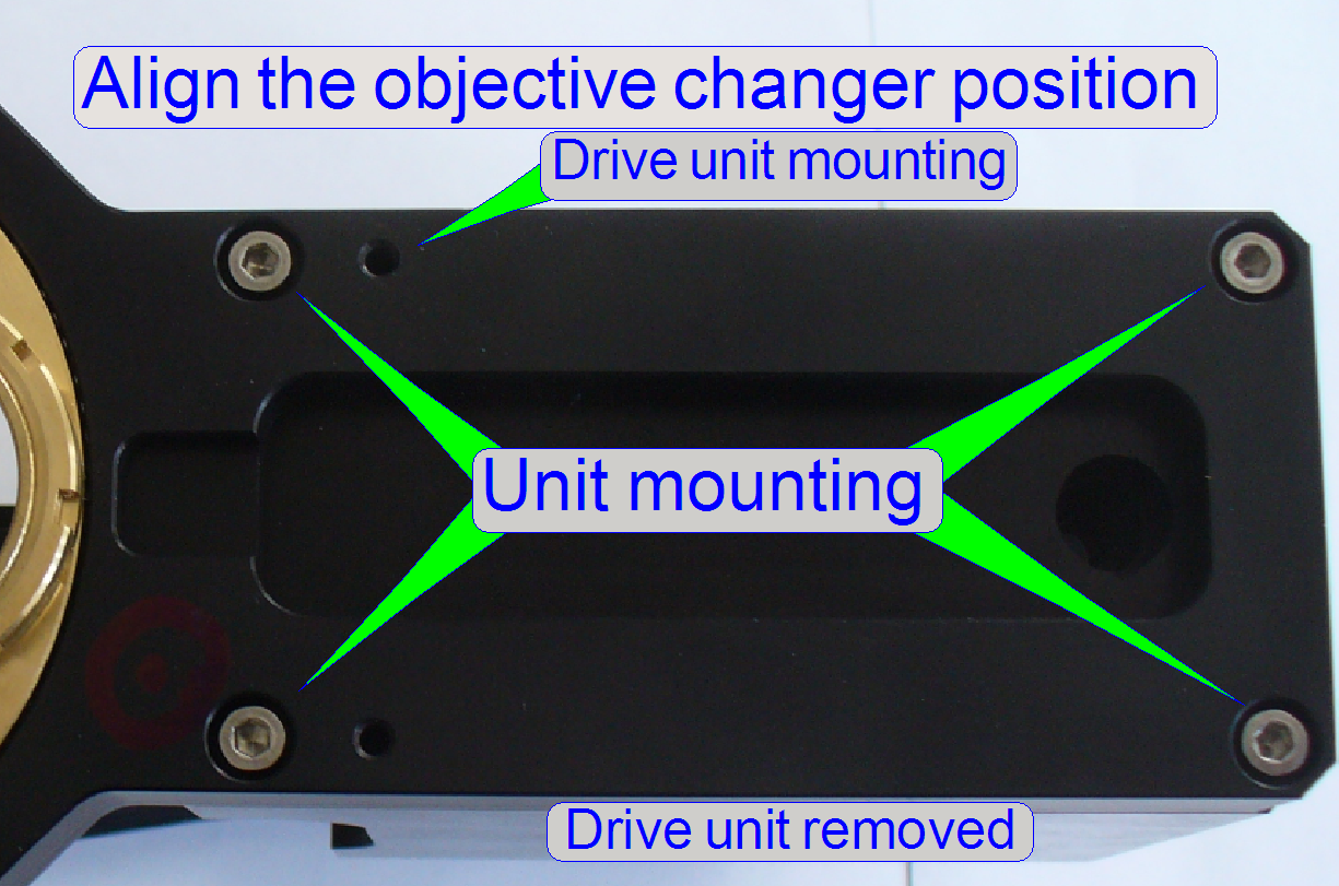
position can be adjusted by the help of fitting rings.
- The unit
mounting of the objective changer mechanics should not be loosened or removed, because the working
position of the objective in relation to the optical axis is adjusted
here;
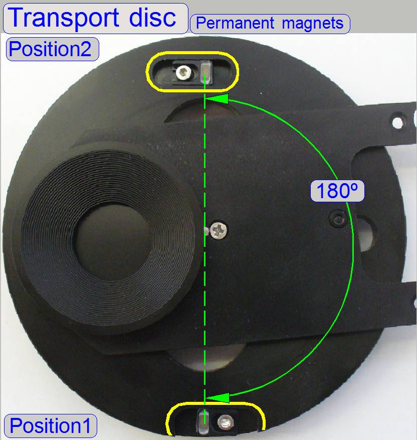
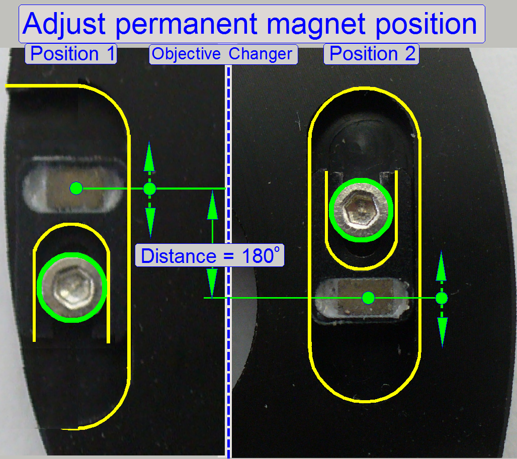
As mentioned above, on the top of the transport disc two permanent
magnets are situated; the distance to each other is exactly 180 degrees (not
shown correctly).
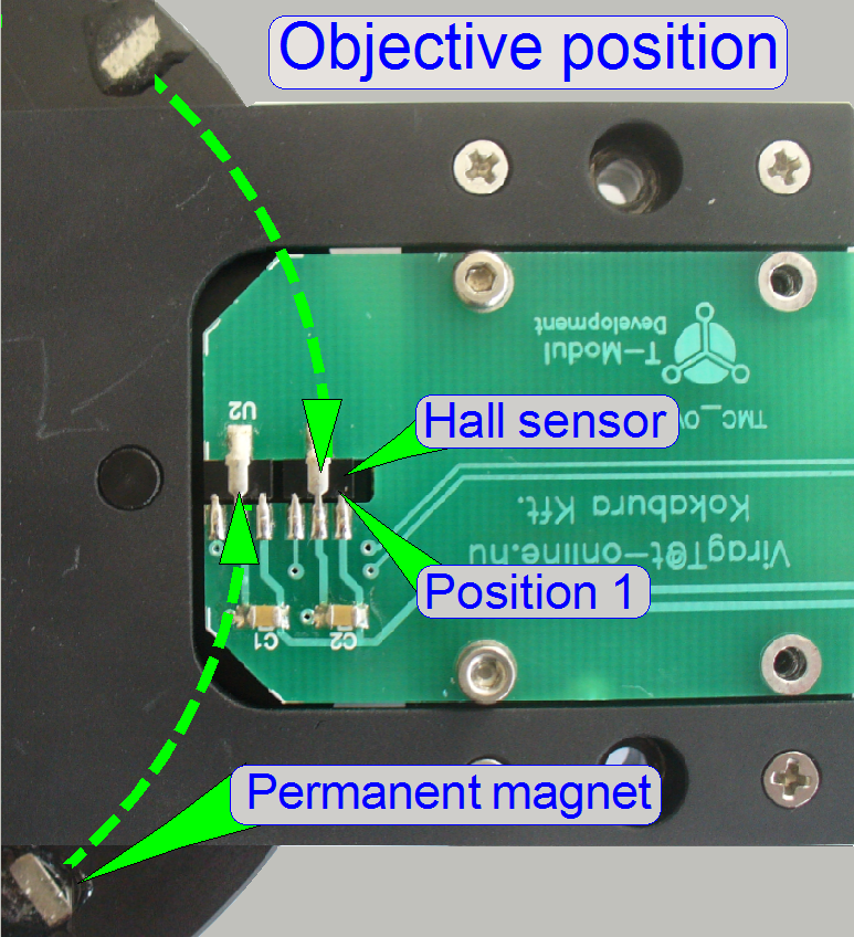
Just before the working
position of the objective is arrived and the dead point of the form-fit
mechanism is even crossed, the permanent magnet arrives over the sensor and
stops so the movement of the transport disc.
- Each objective (position) has its own
sensor and its own permanent magnet also; the positions are named as
“Objective position
- In the objective position 1 always the 20x
objective has to be mounted; in the objective position 2 the dummy objective
or the 40x objective is situated.
- The objective positions 1 and 2 of the
objective disc are decided, if the drive unit will be mounted; see also “Mount the
objective changer drive unit”
Adjustable permanent
magnet position
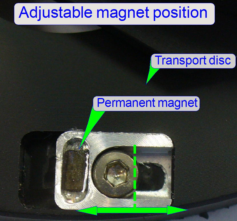
In scanners, manufactured
since June 2013, the position of the permanent magnet is adjustable.
With this solution, and by
adjusting the magnet position, the dead point of the form-fit mechanism can be
always reached surely.
·
If one permanent magnet position is moved backward (or
forward) the permanent magnet in the opposite position should be moved also
backward (or forward) by the same distance!
·
To
reach a correct adjustment, the distance of the permanent magnets to each other
has to be always 180º!!
With this solution, and by adjusting
the magnet position, the dead point of the form-fit mechanism can be always
crossed surely.
![]() “Adjust permanent magnet position”
“Adjust permanent magnet position”
Watch video: “P250_Objective change”
·
If one permanent magnet position is moved backward (or
forward), the permanent magnet in the opposite position should be moved also
backward (or forward) by the same distance!
·
To
reach a correct adjustment, the distance of the permanent magnets to each other
has to be always 180º!!
Adjust permanent magnet position
With the service program
rotate the Transport Disc in forward direction.
If the motor is switched off,
the form-fit mechanics should act and the final objective position should be reached
surely.
Otherwise, a small gap should
also exist between transport hole and transport pin, if the objective stays in
the optical axis.
Check this behavior in both
objective positions several times with the service program!
Watch video: “P250_Objective change”
·
If one permanent magnet position is moved backward,
the permanent magnet in the opposite position should be moved also backward by
the same distance!
·
To
reach a correct adjustment, the distance of the permanent magnets to each other
has to be always 180º!!
The objective disc realizes
the exchange of the objective between two slide scanning sessions.
If the transport disc (not
shown) rotates by a half revolution, the objective disc will be rotated also as
long as the connection between transport hole and objective fitting pin exists.
The force of the form-fit mechanism is defined by its spring and this holds so
the objective (the ball bearing of the fitting pin) always in the proper
position until a new objective change command is executed.
·
The objective disc can be rotated manually in any
direction to reach the required objective position.
·
The form-fit mechanism should always fix the objective
position; otherwise, the optical axis will be incorrect!
The form-fit mechanism acts in the transport disc’s stop position;
the final objective position (the real working position) will be reached and
the fitting pins will be disconnected from the transport holes.
The force of the spring as
well as the shape of the form-fit arm guaranties always the proper and constant
position of the objective in relation to the optical axis.
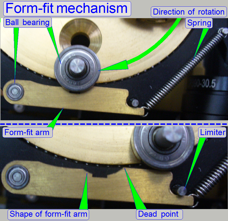
The disc is always driven in direction
from the spring to the mounting of the form-fit arm; the reason for this is the
shape of the form-fit arm.
The use of ball bearings on
essential, important mountings guarantees the proper position of the objective
in the image path.
If the ball bearing of the
fitting pin arrives to the form-fit arm, and the dead point of the form-fit
mechanism is even crossed, the transport wheel stops the movement and the ball
bearing of the fitting pin will be locked in the shape of the form-fit arm by
the force of the spring.
The transport hole of the
transport wheel moves the objective disc with the help of the objective fitting
pin until the appropriate magnet
arrives over its sensor. This position is so defined, that the dead point
of the form-fit mechanism is even crossed.
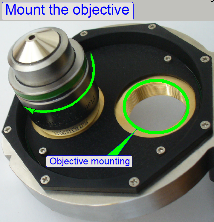
 Objective
mounting
Objective
mounting
The objective disc contains 2
drillings with M27 thread, so the objective can be mounted directly.
The distance of the objective
to the focus pin (the objective position) is adjusted by using fitting rings
between the objective mounting surface and the objective disc surface.
The nominal distance is
0.3mm.
By using and combining
fitting rings of different thicknesses, the objective position can be adjusted
individual; but this is strongly not recommended for Plan_APOCHROMAT type
objectives.
If the objective was removed,
please insert the 20x objective into the mounting with the marker again, the
objective position was adjusted with this condition.
Set of objective fitting
rings
Name: SHIMS
SET FOR M27 OBJECTIVE
Article number: AC-OBJ-SHM-0100
Content: Nominal objective position is reached
if the thickness of the fitting ring is 0.3mm!
2x 0.3mm; already implemented
4x 0.1mm
2x 0.05mm
By using and combining
appropriate fitting ring thicknesses the distance of the objective to the
tissue can be adjusted in steps of 0.05mm.
·
Please use always the same distance of the objective
to the tissue on both objectives!
·
Because the Objective distance is already adjusted
(with the fitting rings of 0.3mm), the implemented fitting rings are not found
in the set, delivered with the scanner!
Mount the
objectives
Important
Principally, the objective
position is already adjusted during the system integration process and
modification of the objective position should be done only in exceptions;
·
modification
is strongly not recommended!
·
If the objective(s) are dismounted, please leave the fitting
ring(s) on the objective (to avoid a mismatch)!
·
Always drive the 20x objective into the marketed
position, see above!
·
Always drive in the objective until it stops!
The focus position of both
objectives is found in the nominal focus position for the appropriate slide
thickness within a tolerance of ±50 focus steps!
Dummy objective
If the option 40x
magnification is not used, the dummy objective is implemented in the objective
position 2.
This way, a weight
displacement of the objective disc will be avoid; mainly used in SCAN and P250-type
scanners.
- If a weight displacement of the objective
disc would occur, the form-fit mechanism would not work correctly and the
objective may be misaligned in the optical axis.
Mount the 20x objective
always into the position 1 and the 40x or dummy objective into the position 2.
- Because in all systems (M_II, S_II) always
a 20x objective is used (the 40x objective is optional) the start-up
procedure of the software calibrates the system with the 20x objective.
- Furthermore, all the optical and preview
adjustments are based on the 20x objective.
- The objective positions 1 and 2 are
decided, if the drive unit will be mounted; see also “Check / Set the working
position
Remark
Since the software version 1.16 the BF scan session may be executed with
the 20x or the 40x objective likewise.
![]() “Upgrade to the
software version 1.16” and “What is new” “Brightfield
scan with the 40x objective”
“Upgrade to the
software version 1.16” and “What is new” “Brightfield
scan with the 40x objective”
 The software setup of
the objectives is done in the dialog “Microscope settings”, there will be
defined if the 40x objective is present or not.
The software setup of
the objectives is done in the dialog “Microscope settings”, there will be
defined if the 40x objective is present or not.
![]() “Pannoramic_250_1.15_User's_Guide_EN_Rev1_FINAL.pdf”
“Pannoramic_250_1.15_User's_Guide_EN_Rev1_FINAL.pdf”
Remark
In the dialog
“Microscope settings”, any objective (20x or 40x) can be set to any position
(objective position 1 or 2), but we recommend the use of the objective 20x in
the position 1 and the 40x or dummy objective in the position 2, because some
adjustments (e.g. the
preview calibration procedure) requires the existence of the 20x objective
in the position 1.
Setup and define the
implemented objectives
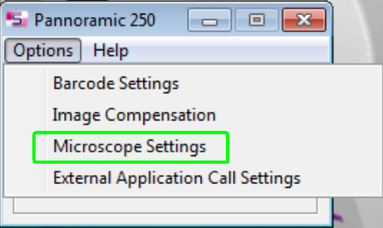 If the
objective(s) are implemented and the program “SlideScanner.exe” finished the
start up procedure, select the option “Microscope Settings” in the menu
“Options”.
If the
objective(s) are implemented and the program “SlideScanner.exe” finished the
start up procedure, select the option “Microscope Settings” in the menu
“Options”.
- The setup of the objective(s) is done
mostly together with the install of the present cameras.
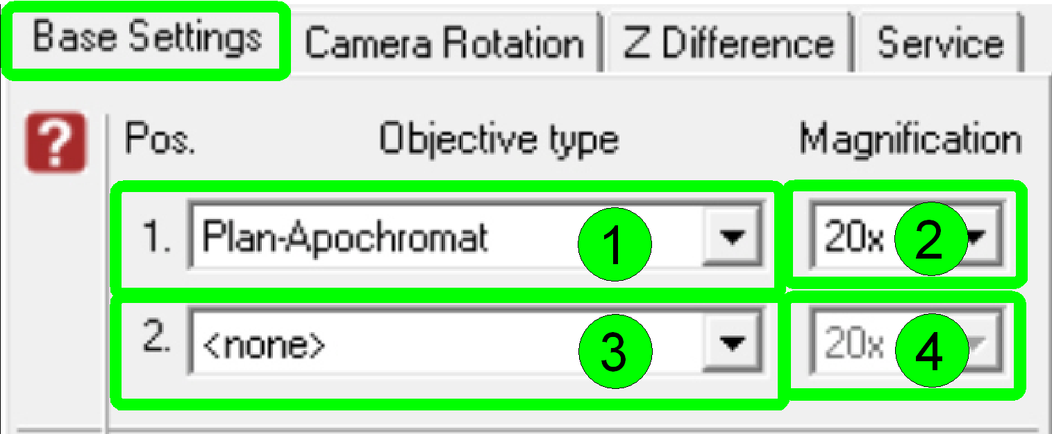 In the dialogue
“Base Settings” the implemented objectives are selected and parameterized.
In the dialogue
“Base Settings” the implemented objectives are selected and parameterized.
By
default
- Select the type “Plan-Apochromat” (1) and
the magnification of 20x (2) in the objective position 1
- Select the type “Plan-Apochromat” (3) and
the magnification of 40x (4) in the objective position 2.
§
If there is only a 20x objective implemented into the
scanner, select “<none>” (3) in the objective position 2.
Remark
Of course, the dialogue
accepts any kind of magnification in any objective position, but in the
Pannoramic 250 the 20x objective should be always in the objective position 1
because this is the default objective and some adjustment procedures (e.g. the preview calibration
process) uses the 20x objective in the objective position 1!

· To exchange the objective, please see “Objective mounting”
This adjustment assumes that the
focus mechanics is fully adjusted.
· Adjustment of the objective position in no longer
required.
· The position of the Plan-APOCHROMAT type objective is
already adjusted by the use of the fitting ring of 0.3mm in each objective
position!
· In exceptions the objective position might be adjusted with the delivered fitting
rings of the set.
Important
Adjustment of the objective
distance to the tissue might be required if another objective type is used
(other than Plan-APOCHROMAT)

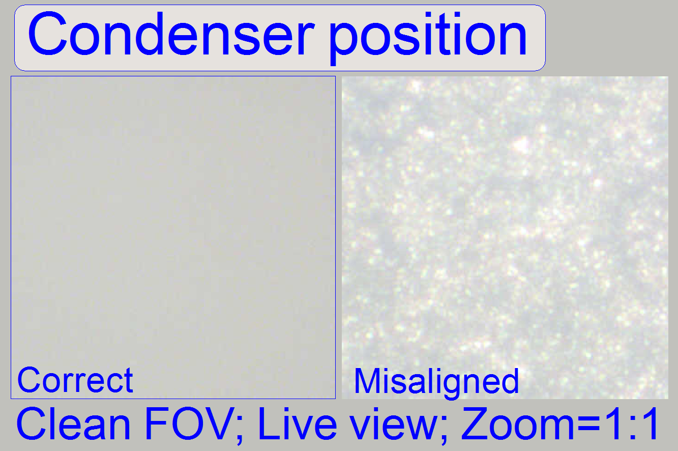
The adjustment of the
condenser is important for the bright, uniform and optimal illumination of the
FOV. This reduces so the exposure time of the camera and increases the quality
of the scanned tissue. If the objective position was modified, the correctness
of the condenser position has to be checked again!
·
This adjustment assumes that the entire focus unit is
adjusted and the correct objective position is found; this should be always the
last adjustment of the focus unit.
See also: “Condenser and mounting”
1. Create a live view
with the scan camera in the focus tab and set the focus motor position to 1600 steps.
2. With the preview positioning tool ![]() find a
“clean” FOV outside the tissue and inside the cover slip, without dust.
find a
“clean” FOV outside the tissue and inside the cover slip, without dust.
3.
Loosen the condenser’s fixing bolt.
4.
Rotate the condenser toward to the
objective, to find the start position for the adjustment; the brightness will
increase.
5.
Rotate the condenser in opposite
direction and look at the live view. Beware of the condenser cover (mechanical
shutter), don’t close it and don’t bend it. You will see two surfaces (from the
diffuser) coming into focus (see “Condenser 1 and
6.
After the second surface just disappeared (Condenser
2) and the live image is smooth and bright (“Condenser position”), stop moving
the condenser and tighten its fixing bolt (the image was done with previously
adjusted illumination. If you are starting the adjustment, the figure
“Condenser position” might be is not so smooth).
7.
If the brightness decreased too much, repeat from step
3.
 Check the shutter closed position
· During a fluorescent FOV is visible on the screen as a
live view, switch on and off the bright field illumination several times with
the service program. If the shutter is in proper position the brightness of the
view must not change.
Check the shutter open
position
· During LUT-adjustment the FOV is visible on the screen
as a live view. Try to bring the shutter wire manually more into the shutter
off position (the -300 limit) and observe the screen. If the shutter is in
proper position the view of the LUT adjustment must not change.
Remark
· If the illumination path is partially cut by the
incorrect shutter position, an evenly illumination of the FOV will never be
reached! This is true for all scanner types.
Align the objective
into the optical axis
 Attention
The alignment of the objective position to the optical
axis is already done and finished; this is not a usual adjustment.
The following calibration
should be done only, if the objective changer unit mounting was loosened,
altered or the objective changer unit was separated and reassembled to the
focus unit; so the optical axis will not be strait.
- The following procedure will be used to fit
the objective (position) into the optical axis correctly.
- In any cases, check the alignment
first, before starting the adjustment.
- Check the correct working of the form-fit mechanics also.
Remark
The aligning procedure is
advised and described for the 20x objective and the objective position 1.
If the 20x objective position
is equipped with an objective nut using Whitworth thread, you can use
unhesitatingly the 40x objective position to align the objective changer unit!
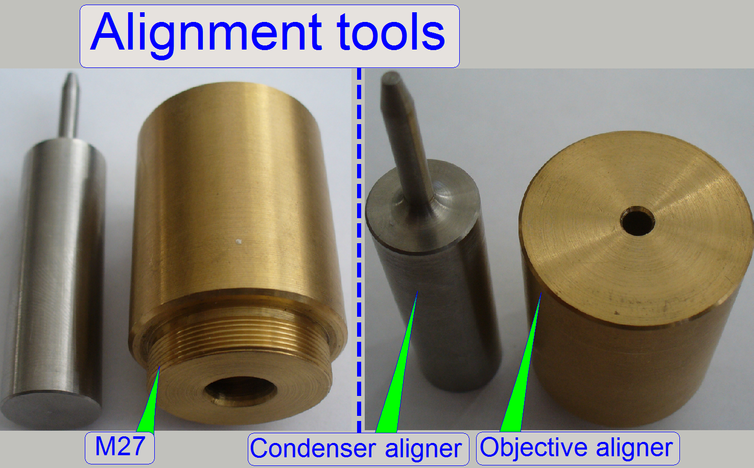 The alignment is
done mechanically; the objective pupil position (represented by the drilling of
the objective aligner) will be fit into the optical axis by the help of the condenser
aligner pin. During this fitting operation the objective changer unit mounting
is barely loosened (except you are checking the correctness of the alignment).
The unit mounting bolts will be tightened, if both adjustment tools fitting
easily and the form-fit mechanics fix the objective position correctly.
The alignment is
done mechanically; the objective pupil position (represented by the drilling of
the objective aligner) will be fit into the optical axis by the help of the condenser
aligner pin. During this fitting operation the objective changer unit mounting
is barely loosened (except you are checking the correctness of the alignment).
The unit mounting bolts will be tightened, if both adjustment tools fitting
easily and the form-fit mechanics fix the objective position correctly.
- In all cases, the lock nut of the objective
mounting nut as well as the objective aligner should be fully tightened
during the aligning procedure.
- The alignment tools can also be used to
check the objective position alignment if the objective changer unit
mounting is tightened!
1.
With the service program set the objective changer
into the default position by pressing the radio button “Sensor
2.
Disconnect the cables of the objective changer and the
stepper motor cables.
3.
Remove the entire
focus unit with the objective changer.
4.
Remove the
drive unit.
5.
Rotate the objective disc manually by about a ¼
revolution and remove the 20x objective; do not loosen the lock nut or the
objective mounting nut; otherwise the objective position has to be adjusted
again!
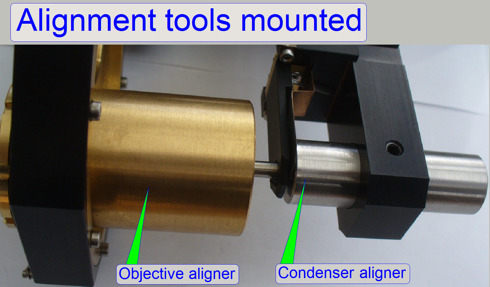
6.
Drive the
objective aligner into the objective mounting of the 20x objective until it
stops.
7.
Mark the condenser position (e.g. with a pen), then remove the condenser.
8.
Make sure, the mechanical shutter is open.
9.
Insert the condenser aligner into the
condenser mounting.
10.
If the condenser aligner moves easily in / out in the
condenser mounting (if it would falling out by gravity) and the form-fit
mechanics fix the objective position correctly, the adjustment is correct.
11.
If the condenser aligner can not be inserted or moves
strong, the objective is misaligned; execute the aligning procedure.
12.
If the aligning result is acceptable, remove the
condenser aligner and mount
the condenser again (until the previously signaled position).
13.
Remove the
objective aligner and mount
the 20x objective again.
14.
Put the 20x objective into the working position
manually and mount
the drive unit.
15.
Mount the entire focus
unit with objective changer and connect the cables.
16.
With the service program check the functionality of
the focus unit and the objective changer unit as well, the 20x objective have
to be in the working position if ‘Sensor
17.
Check or adjust
the objective position.
18.
Check the
focus position
19.
Check or adjust
the condenser position.
1.
With the service program set the objective changer
into the default position by pressing the radio button “Sensor
2.
Disconnect the cables of the objective changer and the
stepper motor cables.
3.
Remove the entire
focus unit with the objective changer.
4.
Dismount the
drive unit.
5.
Rotate the objective disc manually by about a ¼
revolution and remove the 20x objective; do not loosen the lock nut or the
objective mounting nut; otherwise the objective position has to be adjusted
again!
6.
Drive the
objective aligner into the objective mounting of the 20x objective until it
stops.
7.
Mark the condenser position (e.g. with a pen), then remove the condenser.
8.
Loosen the unit mounting bolts of the entire objective
changer unit so, that the unit becomes barely moveable.
9.
Make sure, the mechanical shutter is open.
10.
Insert the condenser aligner into the
condenser mounting and adjust the entire objective changer unit position in
relation to the focus unit.
11.
If the condenser aligner moves easily in / out in the
condenser mounting (if it would falling out by gravity) and the form-fit
mechanics fix the objective position correctly, the unit mounting bolts should
be tightened.
12.
Check the easily movement of the condenser aligner in
the condenser mounting again; hereby the form-fit mechanics should fix the
objective position correctly also.
13.
If the condenser aligner moves strong, repeat this
procedure from step 8.
14.
If the aligning result is acceptable, remove the
condenser aligner and mount
the condenser again (until the previously signaled position).
15.
Remove the objective aligner and mount the 20x objective
again.
16.
Put the 20x
objective into the working position manually and mount the drive unit.
17.
Mount the entire focus unit with objective changer and
connect the cables.
18.
With the service
program check the functionality of the focus unit and the objective changer
unit as well, the 20x objective have to be in the working position if the radio
button “Sensor
19.
Check / adjust
the objective position.
20.
Check the
focus position
21.
Check / adjust the
condenser position.