Housing, construction;
S_II
For technicians!
This chapter handles components of the housing and mechanical
construction of the scanner Pannoramic SCAN_II (S_II).
Usually, as common known, the painting of internal units and components in
scanners as well as in microscopes and other optical equipments is black.
- Colors in the
images are used to distinguish units and components.
·
For safety regulations regarding
human health and scanner functionality please refer to: Precautions
Enhancements
Following improvements are done in the scanner
Pannoramic SCAN, delivered since summer 2016
These modifications do not result in another scanner type, but to bundle
all the modifications, the term SCAN_II (S_II) was created and is used
internally.
Scanners, delivered since summer 2016 including all the following
improvements and modifications, appropriate replaced units, used in previous
versions are no longer delivered in manufactured scanners.
Housing
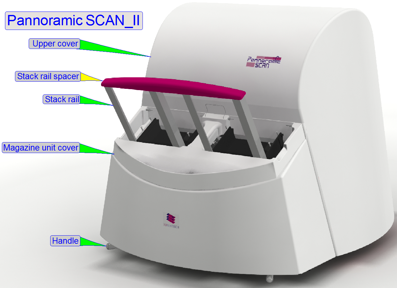
The color of the stack rail spacer is changed to pink; the painting
color of the rear wall is changed to black.
Detailed information about enhancements, see: Enhancements_2016
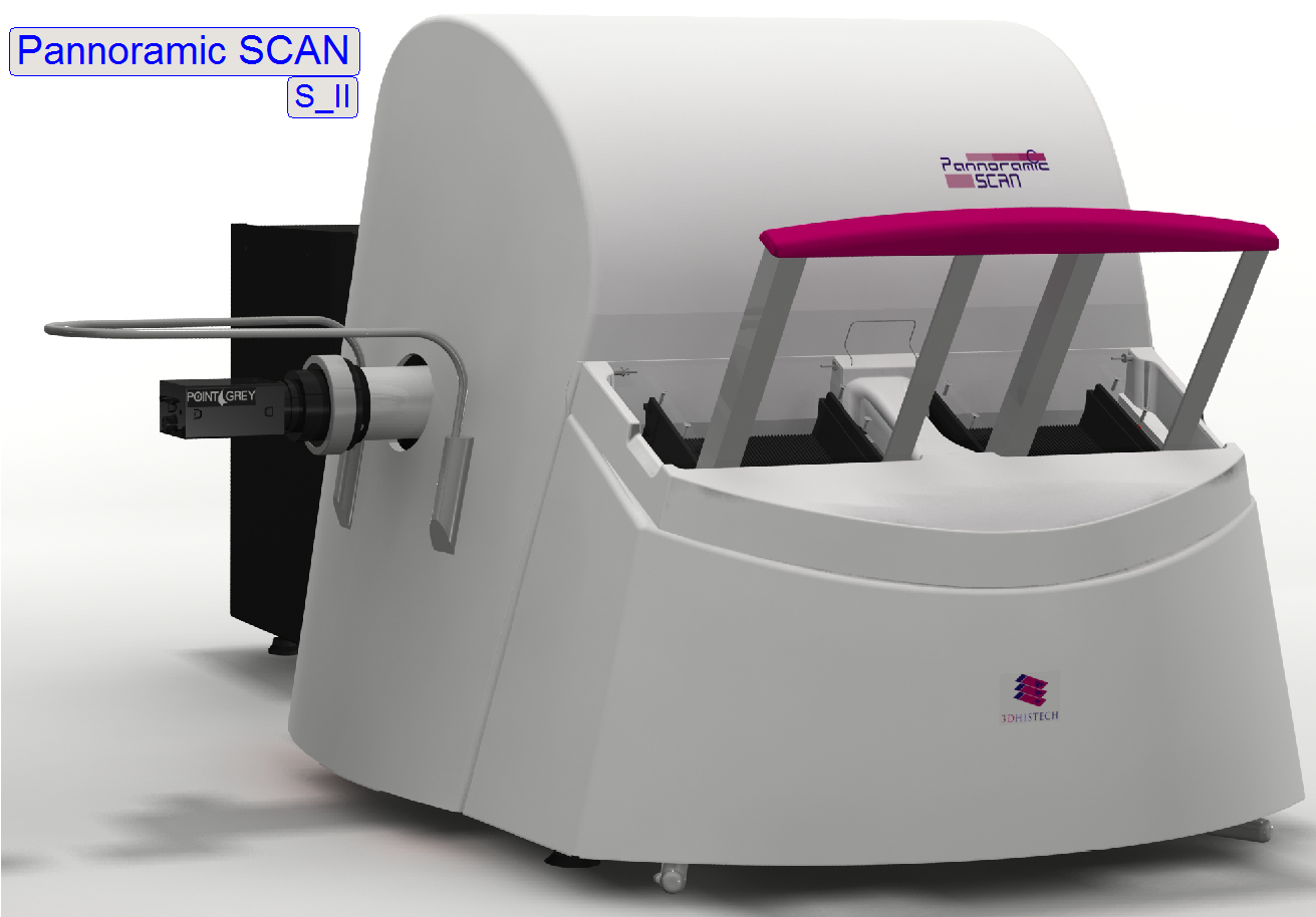
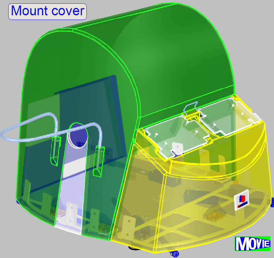
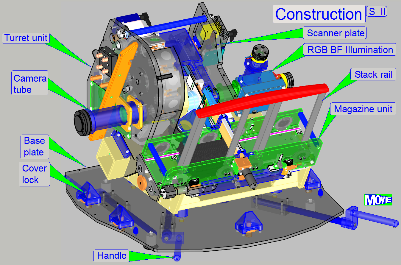
The housing of the Pannoramic
SCAN scanner consists of:
·
The
base plate (with 4 rubber feet, 4 handles for transport, 4 cover fixings to fix the
upper housing and 1 cover fixing to fix the magazine unit cover)
·
The
side wall (its position can be adjusted in relation to the upper housing)
·
The upper housing with the mounting of the camera
protector
·
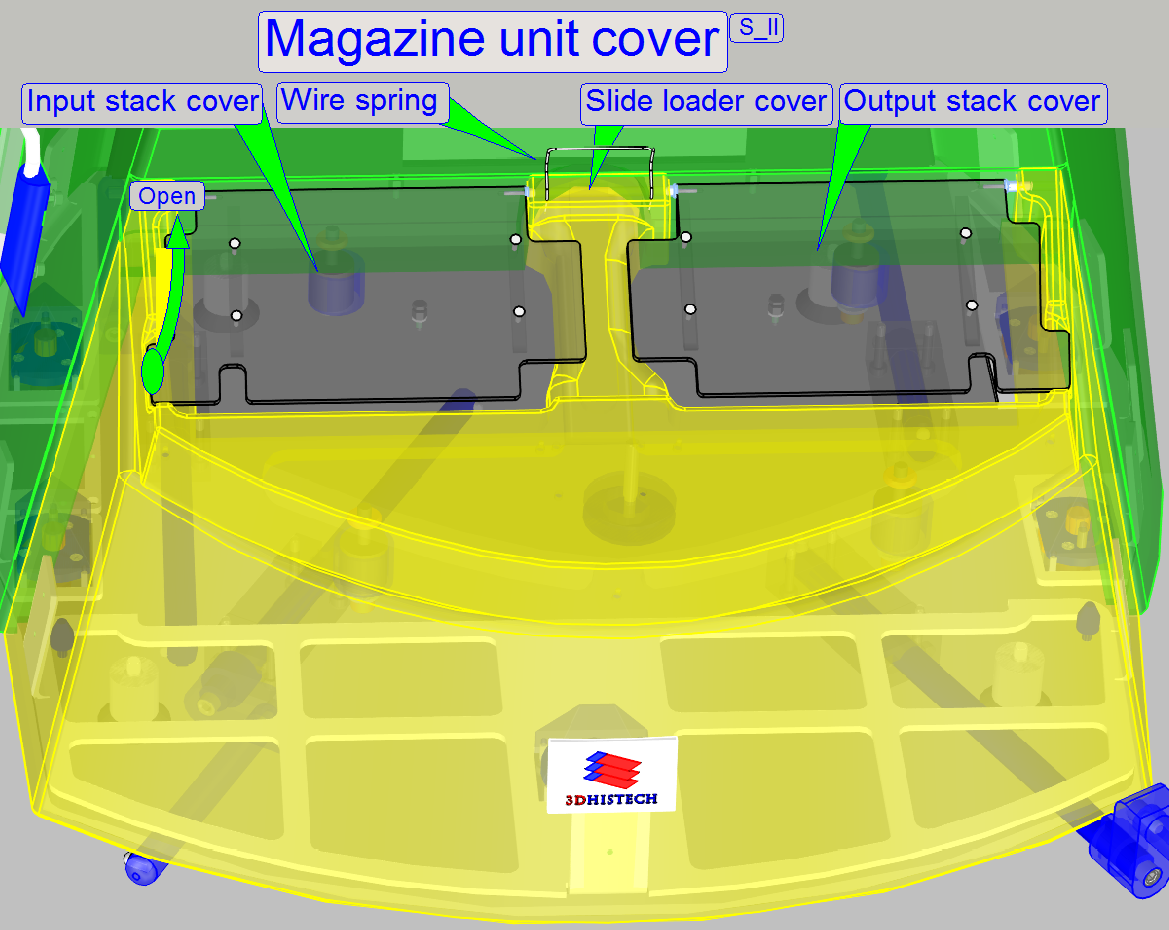
The magazine unit cover with slide loader cover (these
can not be separated)
·
The
back wall (not shown) is mounted with 3 washers and 3 bolts to the base plate
·
The
input stack cover and the output stack cover
Watch Video: SCAN_II
 Its task is to join the stack
rails, fixing their positions in relation to each other and improves the
stability of the magazine loading process.
Its task is to join the stack
rails, fixing their positions in relation to each other and improves the
stability of the magazine loading process.
The stability of the stack rail spacer is not designed
for any movements of the scanner; it is not a handle!
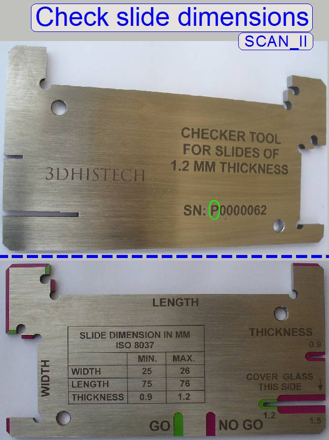 Allowed
slide dimensions are
Allowed
slide dimensions are
Length: 75.00 to
Width: 25.00 to
Thickness: 00.95 to
- If the first
character of the serial number is an “S” the tool is used to check
the slide dimensions of single width slides; thickness = 0.95 ... 1.05mm.
- If the first
character of the serial number is a “P” the tool is used to
check the slide dimensions of single width slides; thickness = 0.95 ...
1.20mm.
·
Please check the slide dimensions before filling the
magazine with slides!
·
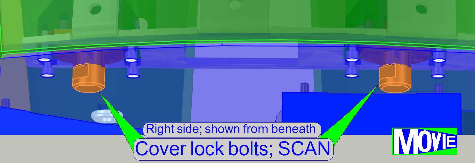
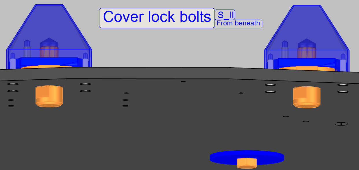
The
cover fixing of the upper housing is realized with 4 cover locks; two on the
left and two on the right side.
·
Drive the cover lock bolts (from beneath)
by a fourth revolution with the open end of the
combination wrench size 10 (delivered with the SCAN) to
open the cover fixing as usually, until it stops.
·
If all the four cover locks are open, the
upper housing can be removed in upward direction
See also: Cover fixing
·
Mount the magazine unit cover first; before you are mounting
the upper housing.
·
Put the upper housing over the scanner and fit the
upper housing with the side wall on the left side.
·
If the lower part of the upper housing fits the base
plate correctly, close all the 4 cover locks (from
beneath) by the use of the open end of the combination wrench size 10 (delivered with the SCAN) to close the cover
fixing as usually, until it stops.
Remove
the magazine unit and slide loader cover
The magazine unit cover can be removed only if the
upper housing and the magazine stack covers are already removed and the handles in
the front are hidden.
·
The cover fixing of the magazine unit
cover is realized with 1 cover
lock in the front of the scanner; and two fixing
pins, one on the left and one on the right side; these fixing pins acting
independently.
·
Drive the cover lock bolt (from beneath)
by a fourth turn with the open end of the
combination wrench size 10 (delivered with the SCAN) to open the cover
fixing as usually, until it stops.
·
If the cover lock is open, the magazine
unit cover can be removed in upward direction
To
mount the magazine unit and slide loader cover
·
Put the magazine unit cover
over the magazine unit, fit the
fixing pins on the left and right side.
·
If the magazine unit cover fits the base
plate correctly, the cover lock can be closed (from beneath) by driving the
cover lock bolt by a fourth turn with the open end of the combination wrench size 10 (delivered with the SCAN) to
close the cover lock as usually, until it stops.
·
Mount the magazine unit stack
covers
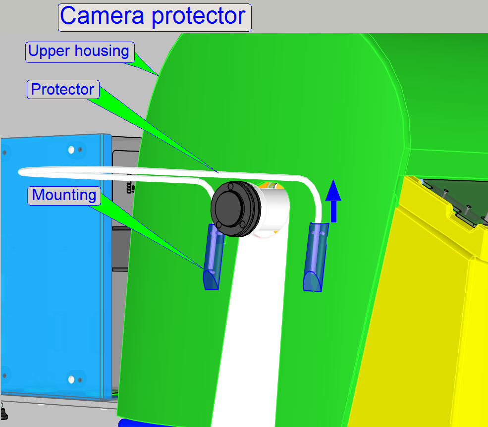
The camera protector is designed to protect the scan camera against
touching from the top or from beside.
·
To remove (mount) the camera protector, pull both parts
evenly upward (push them evenly downward) out from the protector mounting (into
the protector mounting, until it stops).
·
Take care of the upper housing; do not scratch it when
the protector comes out of its mounting!
Watch video: Remove, mount the
camera protector
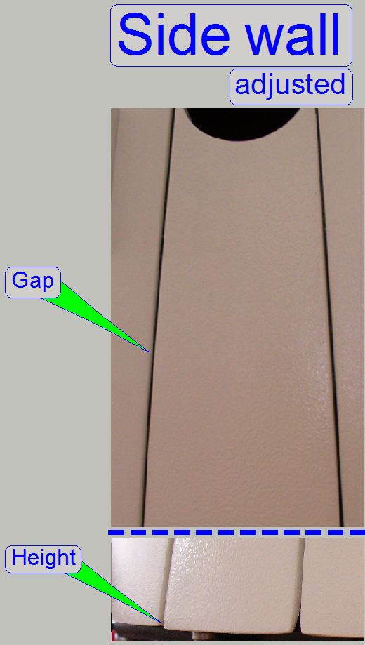
Adjust the position of the side wall in relation to the upper housing of
the scanner.
·
The height of the lower edge of the side wall and the
lower edge of the upper housing should be equal.
·
The gaps between the side wall and the upper housing
should be equal either on both sides of the side wall.
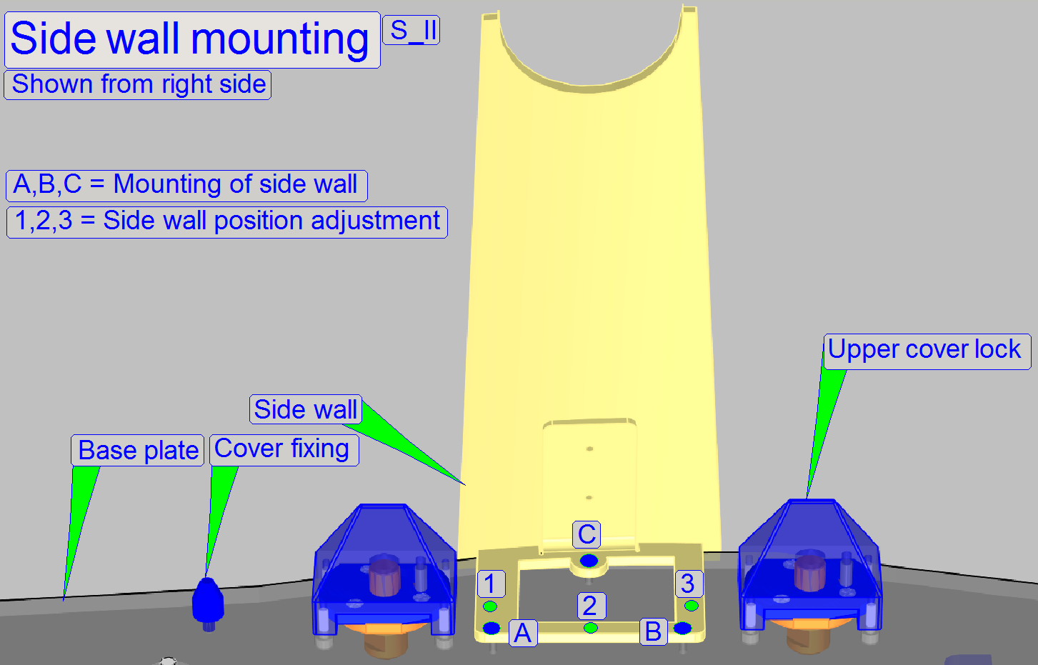
Adjustment
Loosen the mounting bolts A.B,C as required, drive the adjustment bolts
1,2,3 in or out as required and tighten the mounting bolts again.
Fit the upper cover and check the result.
Repeat the steps until the adjustment was successful.
- With this
adjustment the height, the position and the inclination of the sidewall
can be adjusted.
The cover fixing is realized with 5 cover locks; 4 for the upper housing
and 1 for the magazine unit cover.
·
Drive the cover lock bolts by a fourth revolution with
the open end of the combination wrench size 10 (delivered with the
SCAN) to open or close the cover fixing as usually, until it stops.
·
If the cover locks are open, the upper housing can be
removed in upward direction
·
The magazine unit cover can be removed upward only if
the upper housing and the
magazine stack covers are already removed.
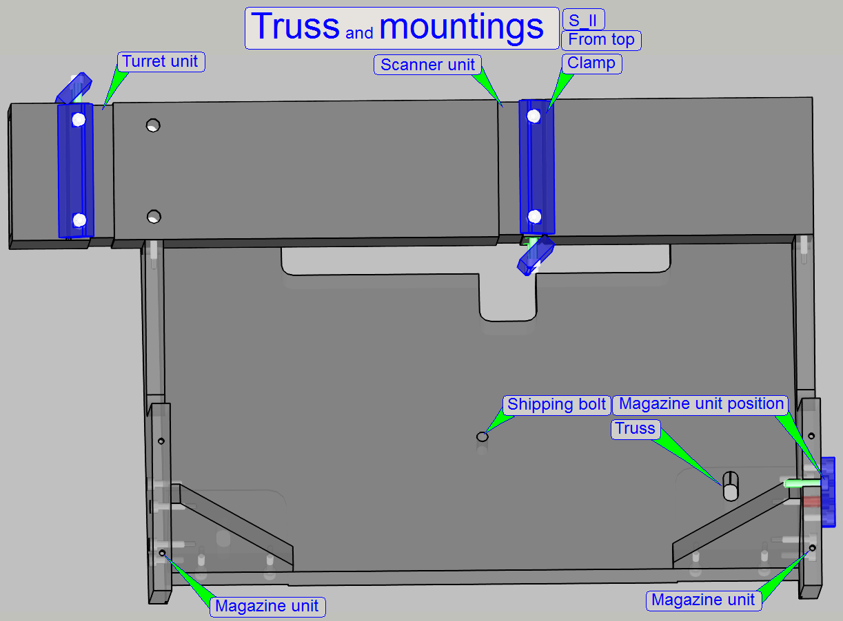
The truss is mounted onto the base plate by rubber feet to reduce vibration
and noise during scanning the sample. During shipping, this solution would
allow that the internal units can crash against the housing. Therefore, to
avoid beating of the housing by internal units, to inhibit the movement of the
truss, and in worst cases the demolishing of the housing, the shipping bolt has to be tightened during shipping.
·
Tighten the shipping bolt e.g. with the ring part of
the delivered combination wrench (size 10) before shipping, and
·
Loosen the shipping bolt after unpacking; before the
first sample will be scanned.
To fulfill requirements of safety regulations in some countries, the
magazine input stack as well as the magazine output stack got an acryl glass cover.
These covers are opened manually by lifting up the lower outer part of the
cover to insert the magazines on the input stack side; on the same way the
output stack cover is opened to remove magazines. If 2 or more magazines are
inserted into the input stack, the cover stays open.
If the magazines are loaded from the input stack into the magazine
channel and only 1 magazine remaining in the input stack, the weight of the
cover itself moves the cover downward and closes so the input channel during
the magazine load procedure is done.
If the 2nd magazine is moved from the magazine channel into
the output stack, the cover will be opened by the magazine and stays open until
the magazines are removed.
Wire
spring
The wire spring on the top of
the slide loader cover guaranties, that the gravity can always close the cover;
the cover must not be moved behind this spring and the spring must not hold the
stack cover.
Realization
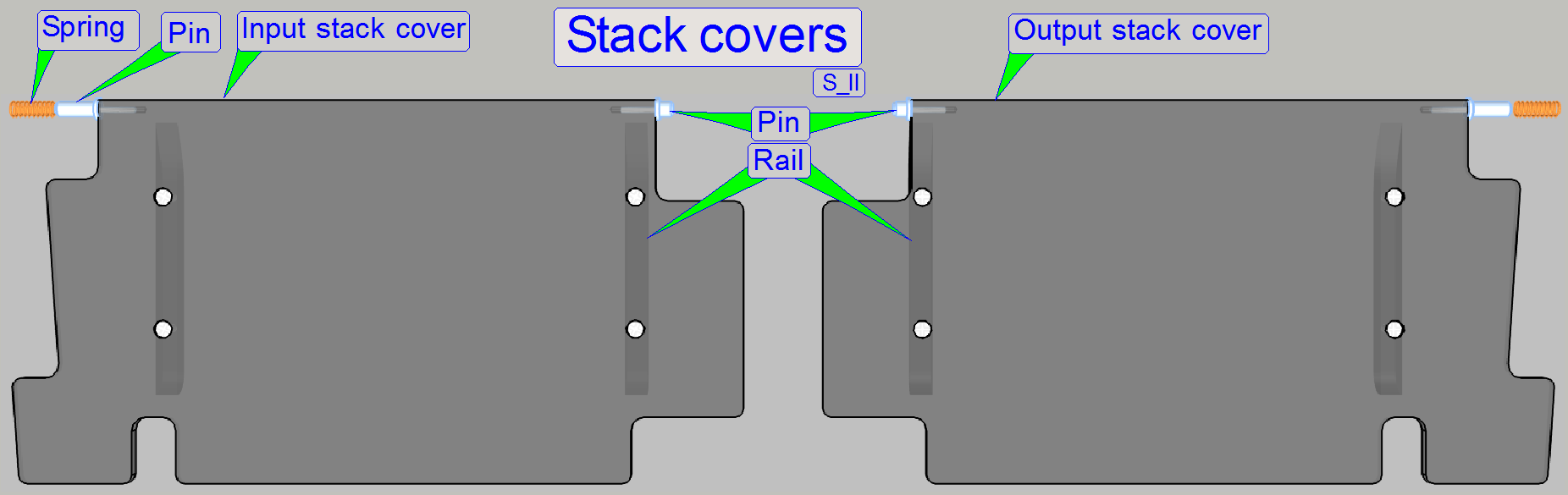 The shape of both covers is identical, but the rails
are mounted onto the opposite side.
The shape of both covers is identical, but the rails
are mounted onto the opposite side.
This way, the different shape of the fixing pins is also situated on the
opposite side. The shorter pin fixes the cover to the slide loader cover; the
longer pin is used to tauten the spring during cover removal or insertion on
the magazine unit side.
The upper corner of the magazines sidewall is in contact with the rails
of the acryl glass cover. The cover is closed by its own weight and gravity.
Spring
The spring is always inserted into the part of the magazine unit cover,
never into the hole of the slide loader cover.
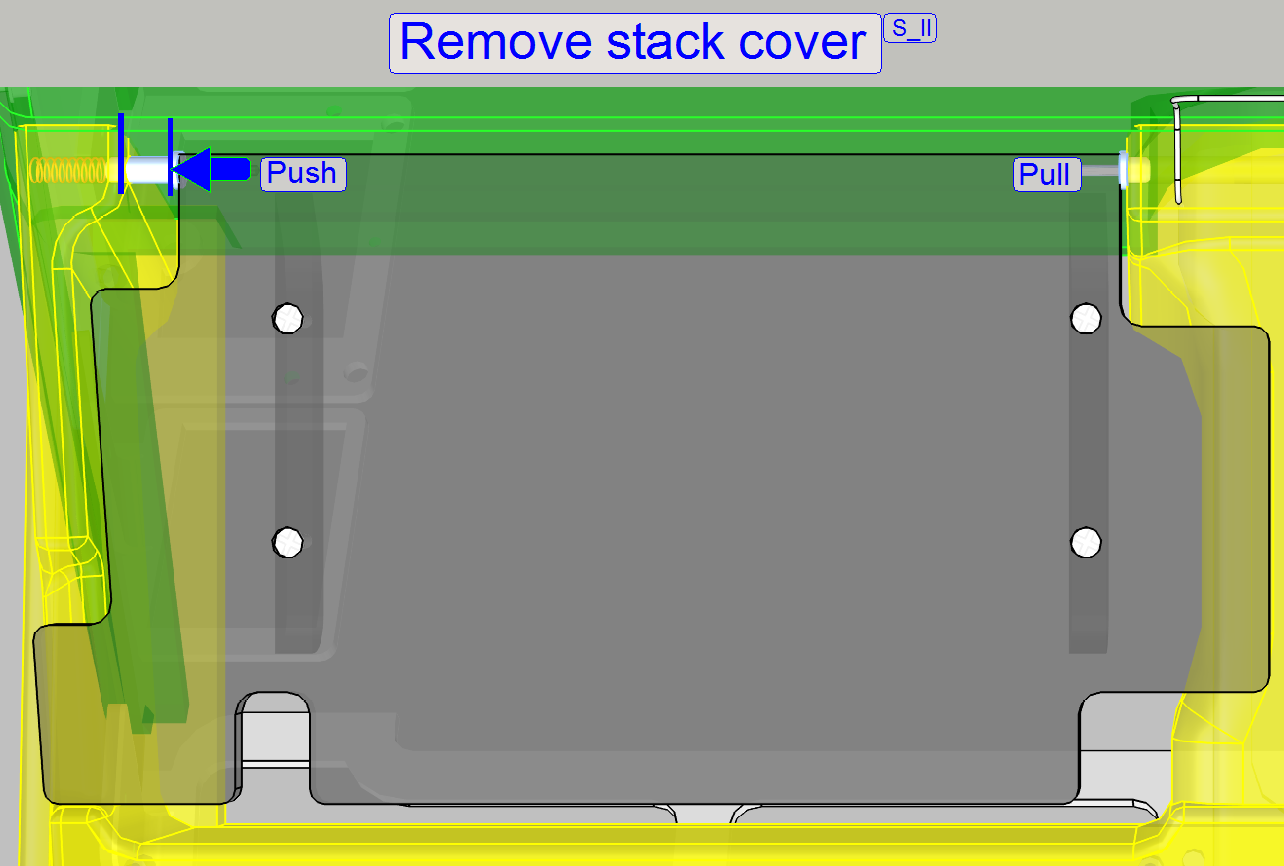
Remove
the input stack cover
1.
Open the cover in an angle of nearly 45º.
2.
Push the input stack cover to the left until it stops
to strain the spring.
3.
Pull the fixing on the right carefully, upward during
the cover is pressed to the left.
4.
Release the pressure on the left side slowly.
- Take care on
the spring; it may be lost easily.
Remove
the output stack cover
Do the steps, described for the input stack cover logically. Because the
spring is inserted in the opposite position, push the output stack cover to the
right and pull the cover on the left side carefully.
Mount
the input stack cover
1.
Make sure, that the spring is inserted well and in the
correct position.
2.
Strain the spring with the longer pin of the acryl
glass cover fixing on the left side and move the right fixing (short pin)
downward; during the spring is strained click the shorter fixing pin into its
place.
Adjust
the position
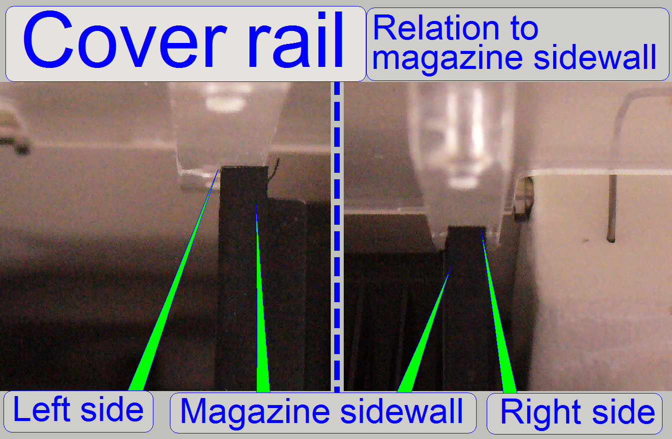 For a well functioning of the magazine load procedure,
even if magazines with only one or a few slides are loaded, the position of the
acryl glass cover rail in relation to the magazine sidewall is very important.
For a well functioning of the magazine load procedure,
even if magazines with only one or a few slides are loaded, the position of the
acryl glass cover rail in relation to the magazine sidewall is very important.
Because the parts of the housing can not be adjusted (except the
sidewall of the upper housing), the
truss position (and so the position of the magazine sidewall) have to be
adjusted.
By loosening the
truss nuts and positioning of the entire truss, the
position of the magazine unit and so, the position of the magazine in relation
to the rails of the acryl glass cover can be adjusted.
2.
Loosen the truss mounting nuts (see below, “The truss”, “truss mounting” and “Adjust the truss
position”).
3.
Insert 3 magazines into the magazine input stack and 3
magazines into the magazine output stack.
4.
Adjust the truss
position so, that the rails of the acryl glass covers are fully over the
sidewalls of the magazine on the input and the output stack side; check all 4
positions.
5.
Tighten the truss mounting nuts.
6.
Insert 6 empty magazines into the magazine input
stack.
7.
Start the magazine load test and check the behavior of
the magazine during the magazine load procedure of each magazine on the input
stack side. The magazine should move evenly and smoothly downward, without
stocking, even if the cover will close. The output of the magazine is not
critical; but stocking of the magazine should also not occur.
8.
If the test is finished correctly, mount the upper cover;
otherwise repeat from step 2.
 Use
the handle
Use
the handle
In the corners of the bottom plate the transport handles are realized.
Pull this handles out of the hidden position and rotate them upward. By using
the handles, the scanner can so be moved safely by two persons. After the
destination is reached, the handles can be hided again.
1.
Pull the handle toward yourself until it stops, then
2.
Rotate the handle upward.
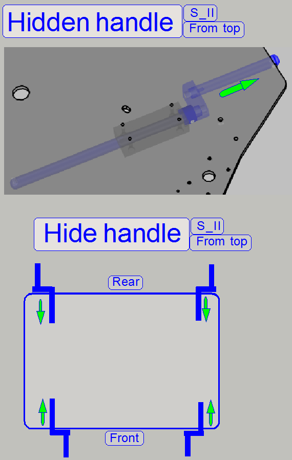
Hide the handle
· Rotate the handles
on the rear horizontally and outward, then shift them frontward until the
handles are hidden; see on the right.
· Rotate the handles
in the front horizontally and inward, then shift them in direction to the rear
until the handles are hidden; see on the right.
Turret and
scanner plate mounting
Turret
and scanner unit mounting
The SCAN consists of the following main units:
·
Magazine unit
with slide
loader
·
FL Reflector turret
unit with camera
tube mounting
·
X-Y-stage unit with specimen holder
·
Focus unit with objective changer and condenser
·
Preview unit with preview camera, preview objective and illumination
·
RGB BF Illumination unit
Watch video: “S_II_Construction”
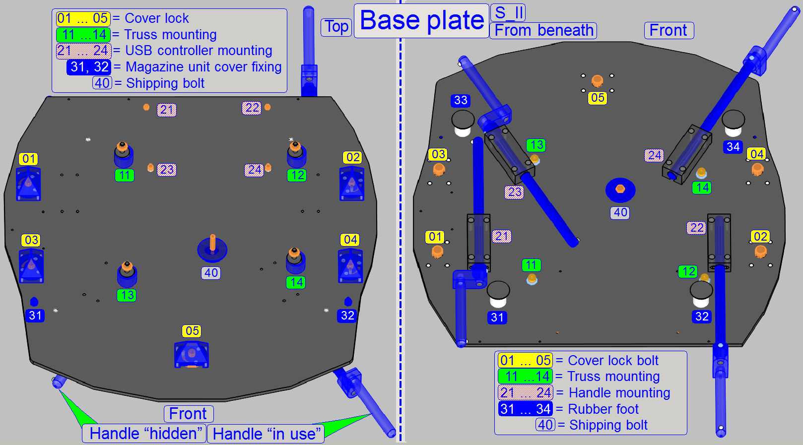
As a part of the housing, the base plate contains the mountings for the
following main parts:
·
Truss
(11 ... 14)
·
USB
controller box (21 ...24)
·
Handles to move the
SCAN (mounted from beneath)
·
Base plate feet 31 ... 34 (mounted from beneath) and
·
Cover
locks for the upper cover (01 ... 04) and the magazine unit cover (05).
·
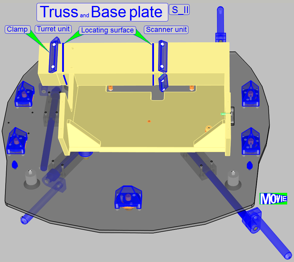
Rubber feet of the truss are mounted with
5mm hexagon bolts to the base plate from beneath (11 ... 14).
The handles are used to move the SCAN.
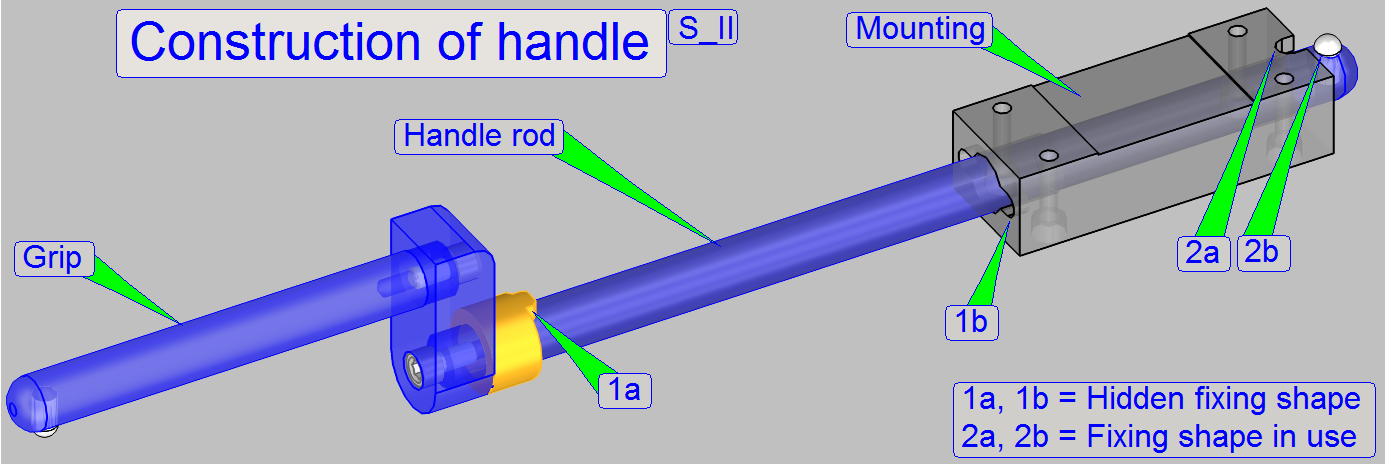 Each handle has two defined positions, the hidden
position and the position "in use" (as shown); in both positions a fixing
is realized.
Each handle has two defined positions, the hidden
position and the position "in use" (as shown); in both positions a fixing
is realized.
The fixing, shown as shapes 2a and 2b are used during moving the scan,
so the handle will not rotate, it stays always upward.
If the handle is pushed into its hidden position, the shapes 1a and 1b fitting
each other and the handle can not rotate downward by gravity.
- Before
rotating the handle sideward during hiding the handle, push the handle a
bit to release the fixing (2).
- If the hidden
position is reached, the fitting of the shapes (1) can be reached by
pushing and jarring the handle grip a bit upward and downward.
The rear wall is mounted with three bolts and washers to the
rear of the base plate in the positions 1, 2 and 3.
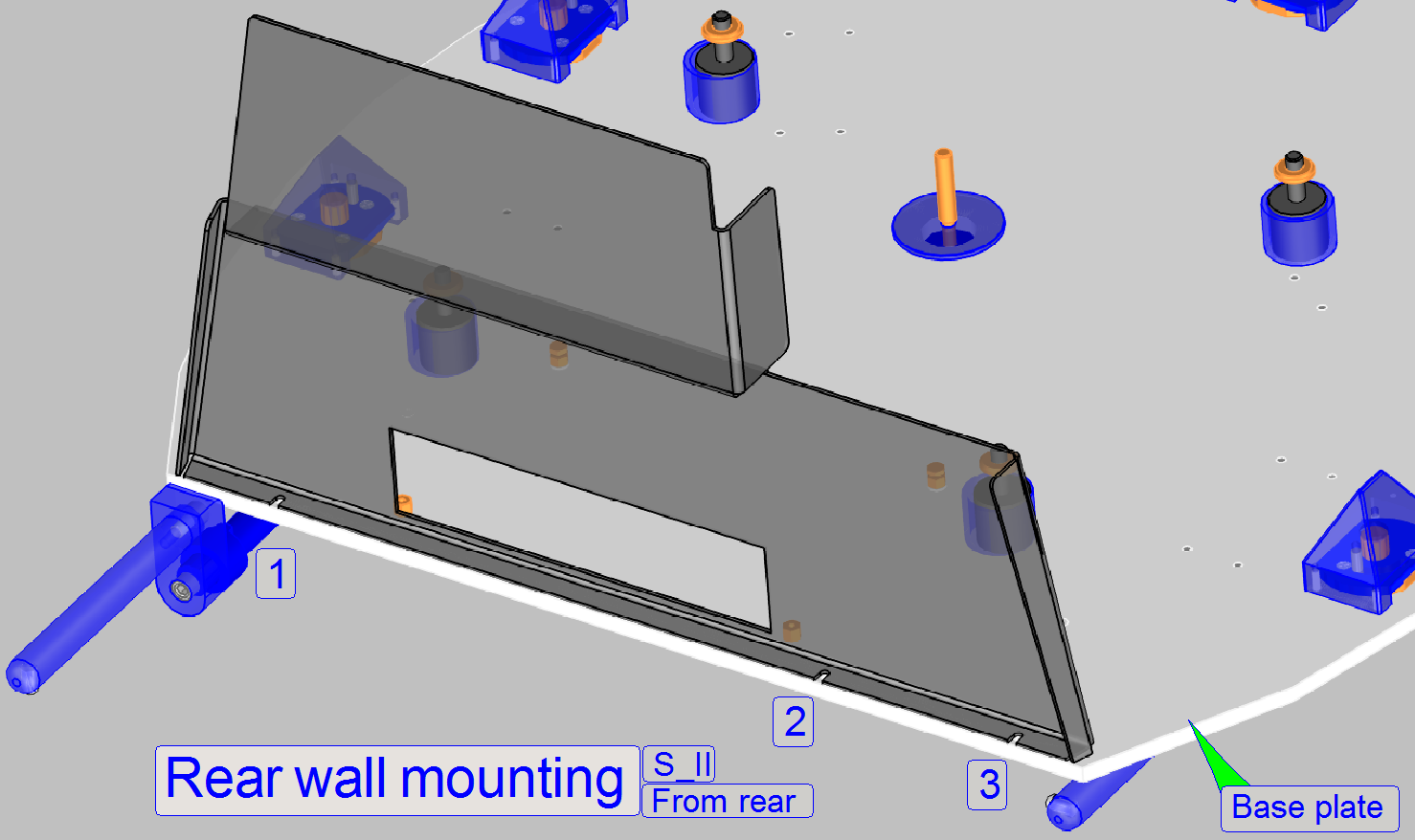 Remove the upper housing.
- If the three bolts
of the rear wall mounting are removed, the rear wall can be removed.
- Mount the
rear wall first, before the upper housing will be mounted.
Shipping
bolt
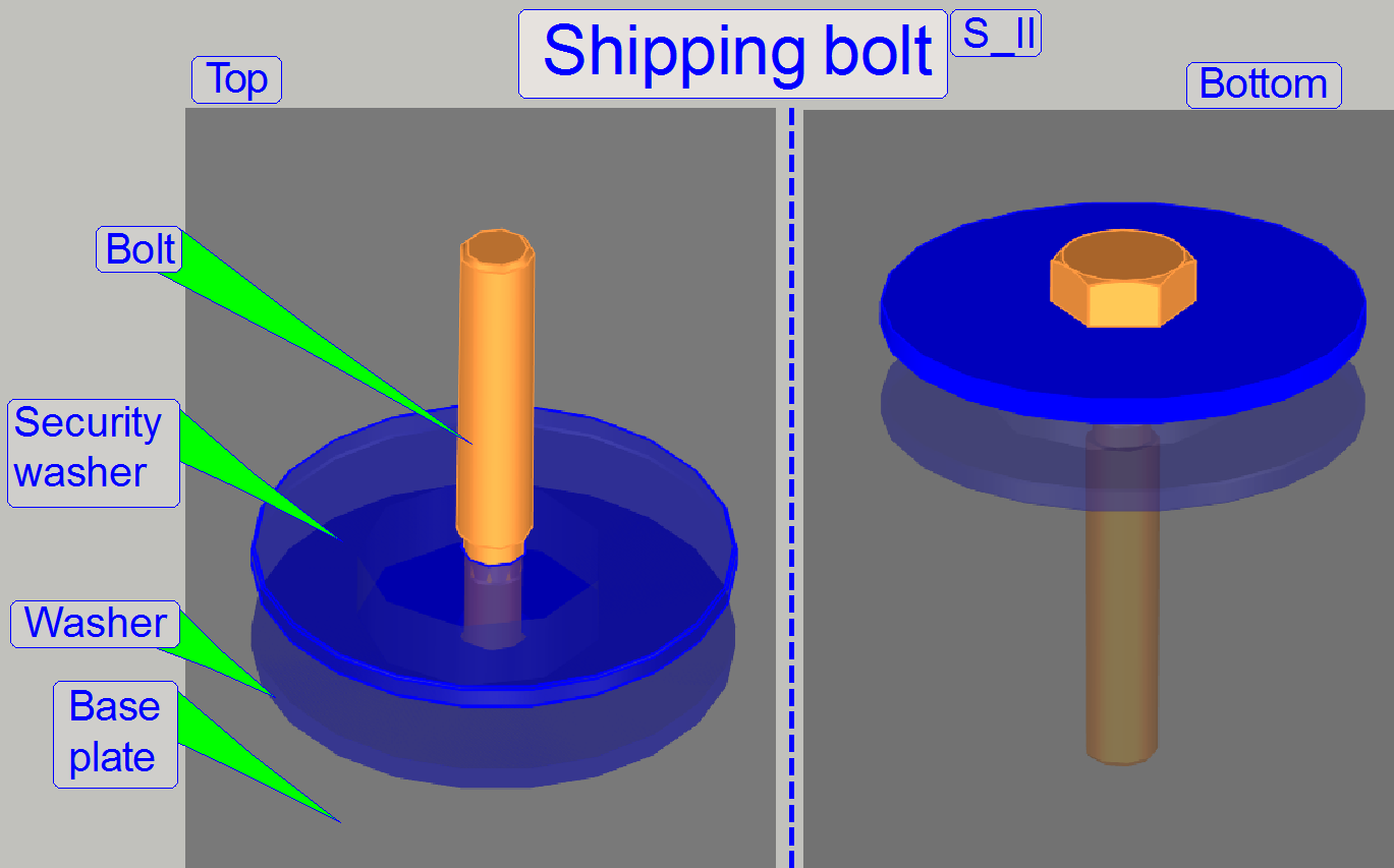 The shipping bolt is secured by a washer, so it
can not be lost if the shipping bolt is fully unscrewed from the truss.
The shipping bolt is secured by a washer, so it
can not be lost if the shipping bolt is fully unscrewed from the truss.
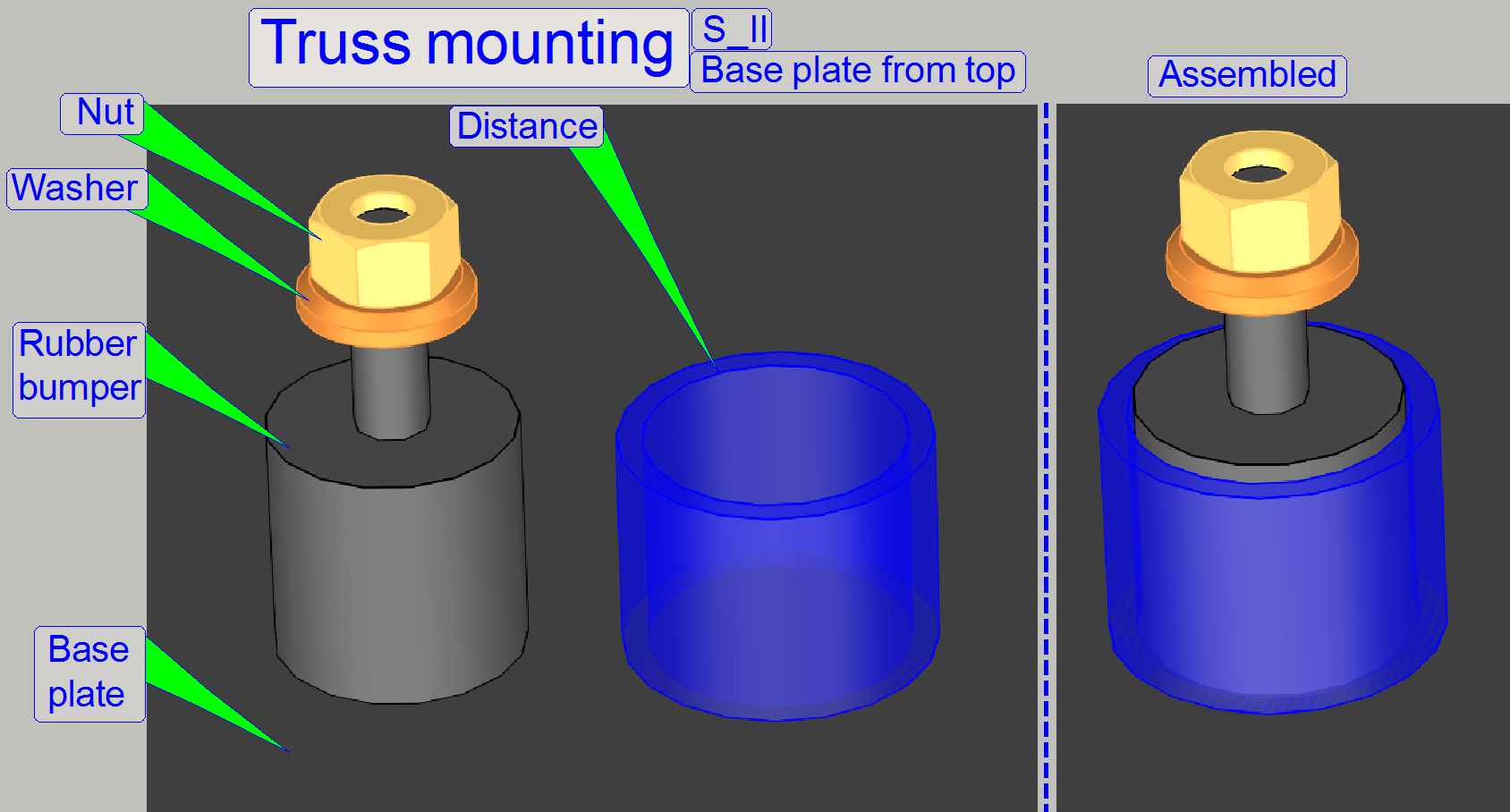 Each mounting for the truss contains a rubber bumper
to reduce noise and vibration during scanning. The rubber bumpers are mounted to
the base plate from beneath.
Each mounting for the truss contains a rubber bumper
to reduce noise and vibration during scanning. The rubber bumpers are mounted to
the base plate from beneath.
If the shipping
bolt is tightened, a distance tube, placed over the rubber part of the
mounting, guarantees the stable fixing of the truss to the base plate.
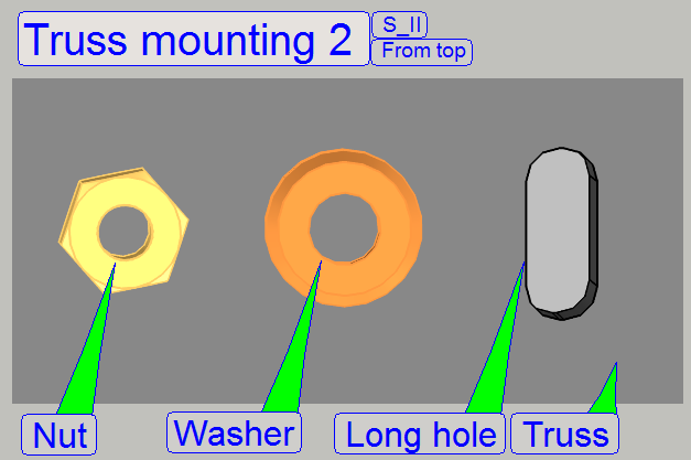
The truss is mounted to the bolts of the rubber bumpers by using a
washer and a bolt nut. With a long hole solution, the position of the truss
(the entire scanner) can be adjusted in relation to the housing; no parts of the
scanner must touching the housing if all covers are mounted; see also “The stack covers”.
To ensure, that the entire scanner does not touch the housing, its position
can be adjusted; see also above “The stack covers”.
The rubber bumpers are mounted from beneath with 5mm hex key bolts and
the truss is mounted to the bolts of the rubber bumpers by using a washer and a
bolt nut.
The long holes in the base plate allow a positioning of the truss in the
mathematical X-direction (left / right) and the long holes in the truss allow
the positioning in Y-direction (front / rear).
·
Adjust the position of the truss so, that no internal
part touches the housing and the stack covers are working
correctly.
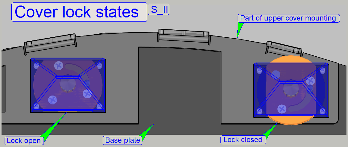
The cover locks are fixing the cover to the base plate. By rotating
their mechanics by a fourth turn with the bolt from beneath, the locks are
opened or closed as shown (use the open end part of the delivered combination
wrench size 10).
Realization
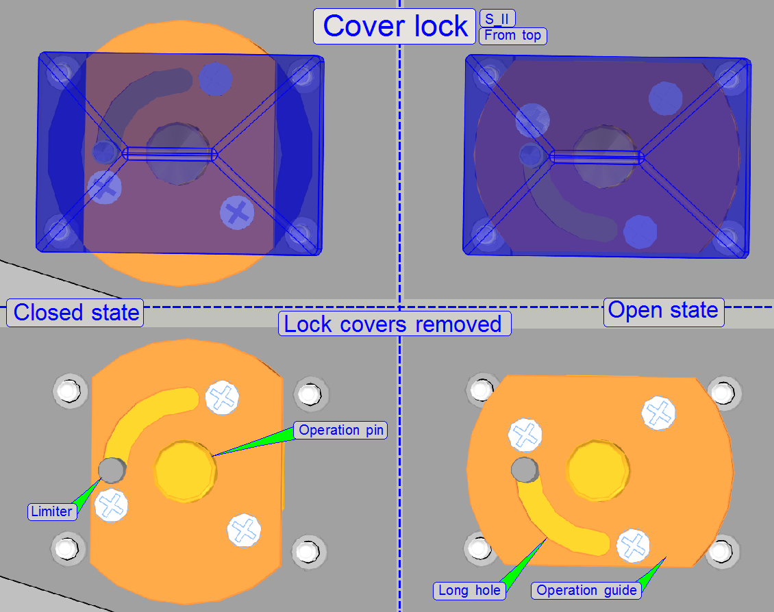
The Limiter is mounted in the cover of the lock, and together with the
curved long hole of the operation guide, the movement of the guide is limited
by a fourth revolution.
The operation pin is driven by the open end wrench from beneath.
Watch video: Cover lock
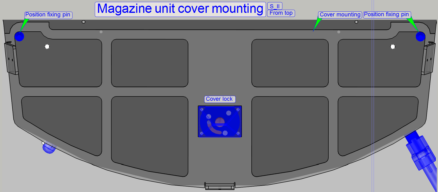
The parallel pin without head
(Position fixing pin) fixes the magazine units cover in its position on
both sides, in relation to the magazine unit cover lock and the base plate.
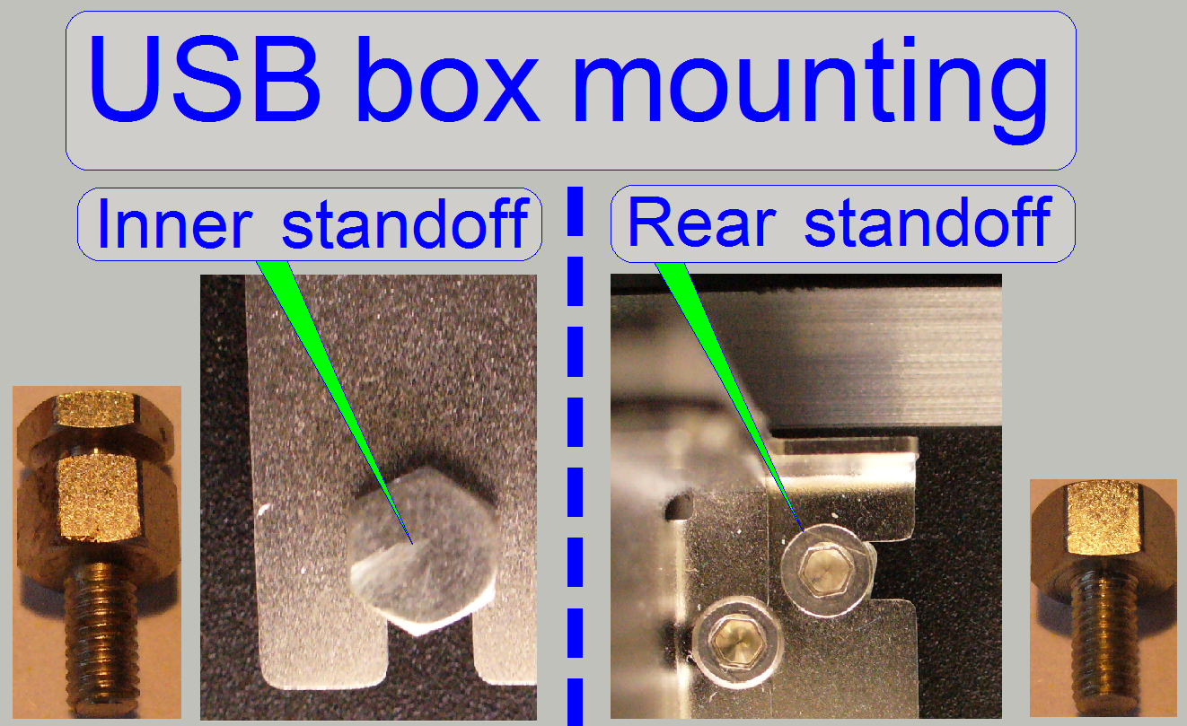
To allow an easily remove and mount of the USB controller box, the
inner, inaccessible standoffs have a slot, in which the unit is shifted in;
during the rear standoffs are fixing the USB box by using a bolt.
Adjust
the truss position
To ensure, that the entire scanner does not touch the housing, its
position can be adjusted; see also above “The stack covers”.
The rubber bumpers are mounted from beneath with 5mm hex key bolts and
the truss is mounted to the bolts of the rubber bumpers by using a washer and a
bolt nut.
- The long
holes in the base plate allow a positioning of the truss in the
mathematical X-direction (left / right) and
- the long
holes in the truss allow the positioning in Y-direction (front / rear).
·
Adjust the position of the truss so, that no internal
part touches the housing and the stack covers are working
correctly.
Watch video: Truss and base plate
Each separate unit of the scanner is mounted on the truss. The truss defines,
with the position of the mountings, the distances of the units to each other.
The mounted main units are:
·
Turret
unit and
Turret and scanner plate
mounting
 The construction
of the mountings defines
The construction
of the mountings defines
- the
straightness of the image path
- the distance
of the units to each other
Watch video: Scanner-Turret-Plate
relations
Optical
path
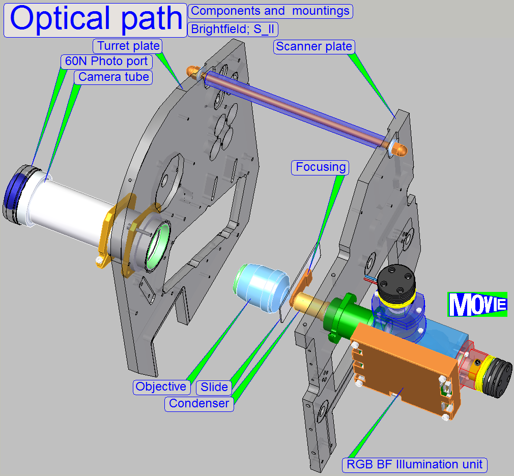 The components of the optical
path as well as the slide load mechanics defining mainly the arrangement of the
units in the scanner.
The components of the optical
path as well as the slide load mechanics defining mainly the arrangement of the
units in the scanner.
RGB
BF illumination unit
 The construction of
the BF optical path uses only a monochrome camera, so only monochrome images
can be produced.
The construction of
the BF optical path uses only a monochrome camera, so only monochrome images
can be produced.
To create color information of the tissue with a monochrome camera, we
illuminate the tissue with monochrome light.
If the tissue is illuminated by blue light, and we are making an image
of the Field of view, the gray scaled camera image contains the intensity of
the blue parts in the tissue.
Because the pixel resolution of the camera is very high and the
resolution of the image's gray scale is 12bit per pixel, very detailed
information of the blue part in the FOV related to the appropriate pixel can be
reached.
If we repeating the procedure with the colors Green and Red, 3 images of
the same FOV are produced and so, the software knows detailed color information
about each pixel of the Field Of View.
By using the software coloring method the true color information of each
pixel is found.
By using cameras with a large image sensor low shutter time and high
pixel resolution (small pixel size), the scan time of the tissue can be held in
acceptable boundaries and the result is an image with high resolution and high
color fidelity.
![]()
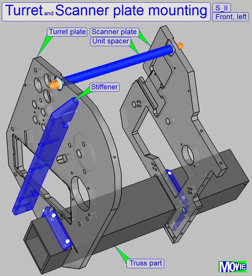
Turret and scanner unit mounting
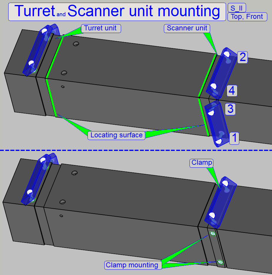 Because the distance between turret unit and scanner
unit is important, the mounting is realized by using a locating surface and the
appropriate unit is fixed by clamps.
Because the distance between turret unit and scanner
unit is important, the mounting is realized by using a locating surface and the
appropriate unit is fixed by clamps.
Only by tightening the clamps in the right sequence, the locating
surface fits correct.
The scanner plate is tightened logically in the same sequence.
To remove the turret plate or scanner plate, loosen the bolts 1 and 3
and remove the clamp, fixed with the bolts 2 and 4; then the plate can be
pulled upward in an angle of 30 degrees.
Modification in summer 2016
The Clamp 1,3 of the scanner unit
is now placed in the front part, because the modified X-Y-stage requires the
space on the rear.
The unit spacer is implemented.
![]() Exchange
the scanner unit Remove the turret
unit from Pannoramic SCAN
Exchange
the scanner unit Remove the turret
unit from Pannoramic SCAN
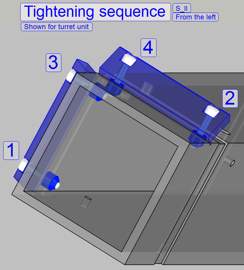
Tightening sequence
After inserting the unit plate, please tighten the clamp bolts in the
shown sequence; only this way, the unit plate will fitting the locating
surfaces correctly.
Turret and scanner unit spacer
The length of the unit spacer is defined by the distance of the locating
surfaces of both units.
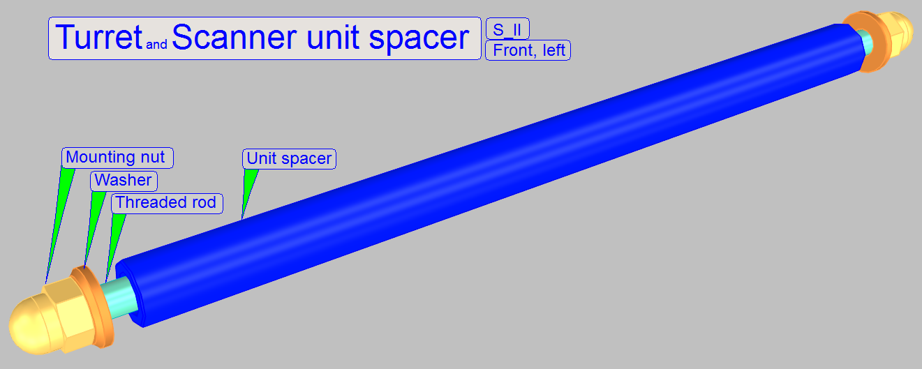 By using a distance spacer, the
straightness of the optical axis is more secure.
By using a distance spacer, the
straightness of the optical axis is more secure.
On the right side of the magazine unit mounting, the magazine unit
position adjustment and fixing is
realized.
With this solution, many adjustments may be left out, if the magazine
unit was removed and mounted again.
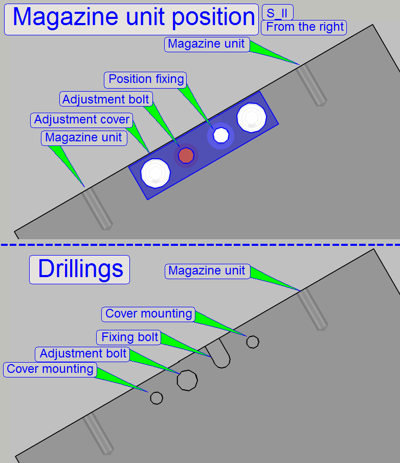
Adjust
magazine unit position
The goal of the adjustment is the fitting of the slide loader position
in relation to the specimen holder position; so a smooth slide insert and slide
removal action can be reached.
- To adjust the
magazine unit position, loosen the magazine unit mounting bolts first.
By loosening the fixing bolt and driving the adjustment bolt inward or
by driving the adjustment bolt outward and tightening the position
fixing bolt, the position of the entire magazine unit can be shifted on the
mathematical X-direction (left / right).
- If the
desired position is reached, tighten the magazine unit mounting
![]() Adjust the
magazine unit position
Adjust the
magazine unit position
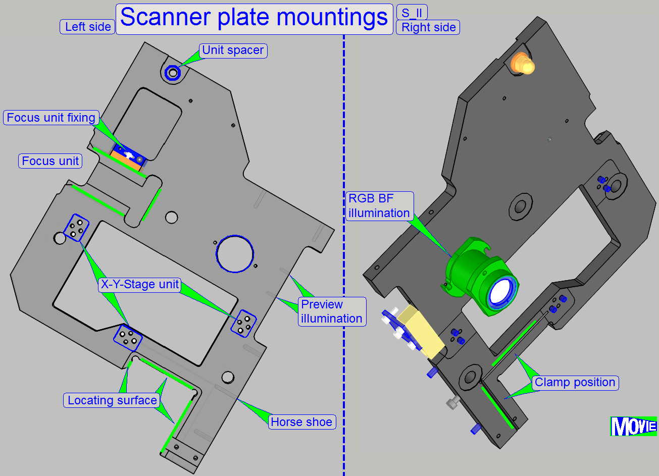 With the locating surface, the correct distance
between scanner plate and turret plate is defined; the scanner plate is mounted
by the use of clamps
and contains the mountings and fixings for the following main units:
With the locating surface, the correct distance
between scanner plate and turret plate is defined; the scanner plate is mounted
by the use of clamps
and contains the mountings and fixings for the following main units:
·
Preview
and barcode unit (the horseshoe) and
·
RGB BF illumination unit
Each unit is inserted until it stops, there must not be a gap between
bumper surface and unit mounting. Only this way the light path will be correct.
Watch video: Scanner unit
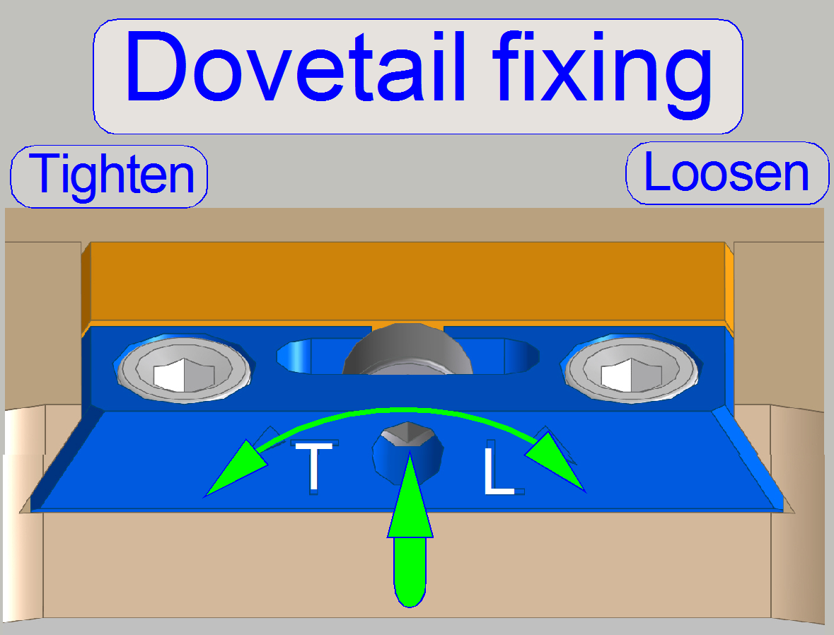
The horseshoe mounting contains two fixing pins to define the position
and a threaded hole for the mounting bolt.
In opposite to the usual rotation direction, the dovetail fixing is rotated
clockwise to loosen the fixing, as shown.
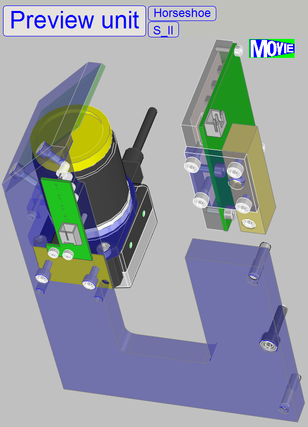
The horseshoe contains the mountings for the components of the preview
unit.
- The preview illumination unit is mounted to the scanner plate
To find the position of the entire tissue to be
scanned or parts of it, a preview of the slide is made.
The tissue is defined as a darker part of the slide in
relation to its surrounding.
Because dust, grease or fingerprints (specks) fulfills
often the same requirement as the tissue itself; specks may be viewed as tissue
also.
- Therefore, keep the surface of the cover slip and the surface of the
slide bottom as clean as possible.
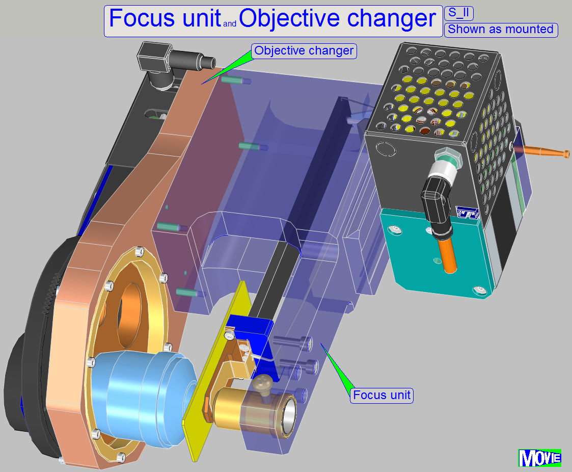 The focus unit is designed to fulfill the following tasks
·
Holding the
objectives Plan-APOCHROMAT 20x/0.8 and Plan-APOCHROMAT 40x/0.95 in the center of
the focus range (realized by the objective changer)
· Focusing of tissues during the scan process on slides with
a slide thickness of 0.95 ~ 1.20mm (done
by the focusing part)
· Concentrating the illumination light to the field of
view (FOV) during brightfield scan procedures (done by the condenser).
· Insuring a dark background during fluorescent scan
procedures (realized by the mechanical shutter)
· Exchanging the objective magnification between two
scan sessions (realized by the objective changer)
X-Y-Stage unit
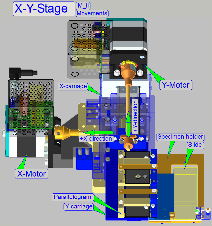 The X-Y-stage unit is used to
position the specimen holder at slide loading and unloading action. It also
moves the slide in X- and Y-direction during the scan process.
The X-Y-stage unit is used to
position the specimen holder at slide loading and unloading action. It also
moves the slide in X- and Y-direction during the scan process.
The movements are realized by
stepper motors. The principle of the slide insertion and specimen holding is
nearly the same in the scanners, so only small deviations are found in the
construction of the specimen holders and these will be discussed separately.
Allowed slide dimensions that
can hold by the specimen holder are 0.95 ~ 1.20mm.
Remark
The X-Y-stage unit mounting
is modified, so a remove and remount of the unit may require excessive
adjustments.
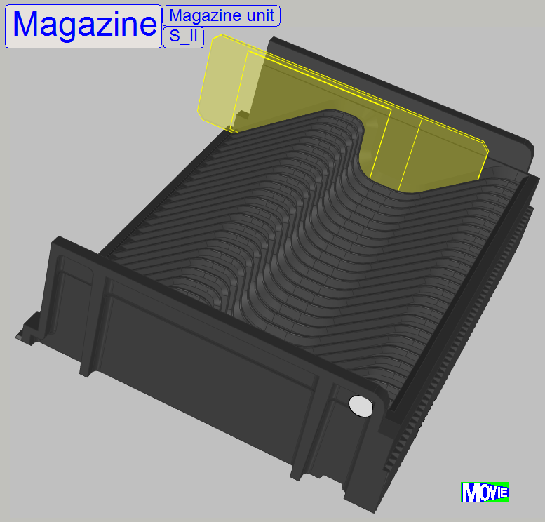
The magazine unit is designed to hold and handle the slides to be
scanned and the slides when the scan process is already finished.
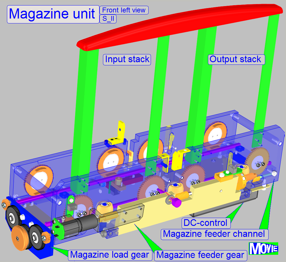 For this, the
slides are stored in magazines with 25 slide positions.
For this, the
slides are stored in magazines with 25 slide positions.
The slide loader, situated at the top of the magazine unit moves the
slide from the actual magazine's slide position into the specimen holder of the
X-Y-stage unit and removes the slide from the specimen holder return, into the
magazine.
By mounting the
magazine unit rotated by 30° against the plumb-vertical, the slides are always
holding at the back of the magazine by gravity. This arrangement influences
also the components and mountings of the optical path and other units.
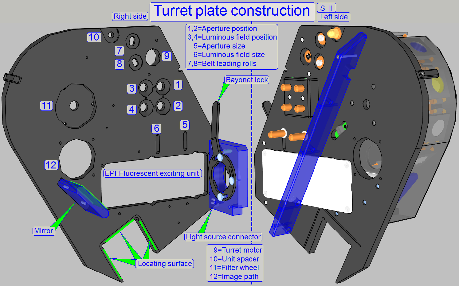
With the locating surface, the correct distance between turret plate and
scanner plate is defined; the turret plate is mounted by the use of clamps
and contains the mountings and fixings for the following main units:
·
Camera tube
mounting (Image path)
·
EPI-fluorescent
illumination unit
Watch video: Turret unit
![]() FL
reflector turret unit; belt driven
FL
reflector turret unit; belt driven
 The Lumencor SPECTRA light
engine is mounted to the light source connector of the turret unit.
The Lumencor SPECTRA light
engine is mounted to the light source connector of the turret unit.
- To make the
exciting light path strait, the height of the light engine holder can be
adjusted.
![]() Lumencor ® SPECTRA light
engine
Lumencor ® SPECTRA light
engine