Focus unit; S_M_D
For technicians and
partly for sales managers!
 These
instructions describe the procedures to install and adjust the focus unit for
SCAN 150, Pannoramic SCAN, Pannoramic MIDI and Pannoramic DESK scanners
(S_M_D).
These
instructions describe the procedures to install and adjust the focus unit for
SCAN 150, Pannoramic SCAN, Pannoramic MIDI and Pannoramic DESK scanners
(S_M_D).
To help resolve problems with the
focus unit a hardware description of the implemented components and adjustment
procedures are added.
The focus unit is designed to fulfill the
following tasks
·
Holding the objectives
Plan-APOCHROMAT
20x/0.8 or Plan-APOCHROMAT 40x/0.95 in the center of the focus range
· Focusing of tissues during the scan process on slides
with a slide thickness of 1.0mm nominal
· Concentrating the illumination light to the field of
view (FOV) during brightfield scan procedures
· Insuring a dark background during fluorescent scan
procedures
Principle of shutter
mechanics
Hardware limits and
shutter on or off
Dismount or
mount the focus unit
For
safety regulations regarding human health and scanner functionality please
refer to: Precautions
 The described
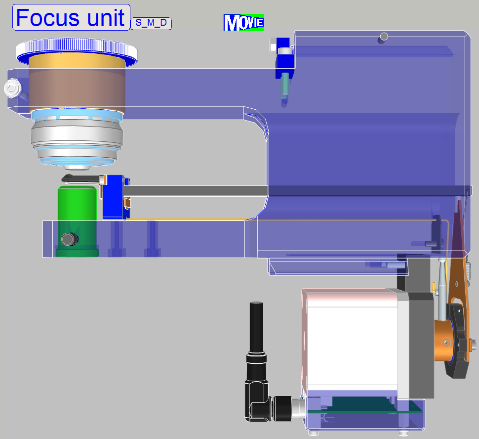
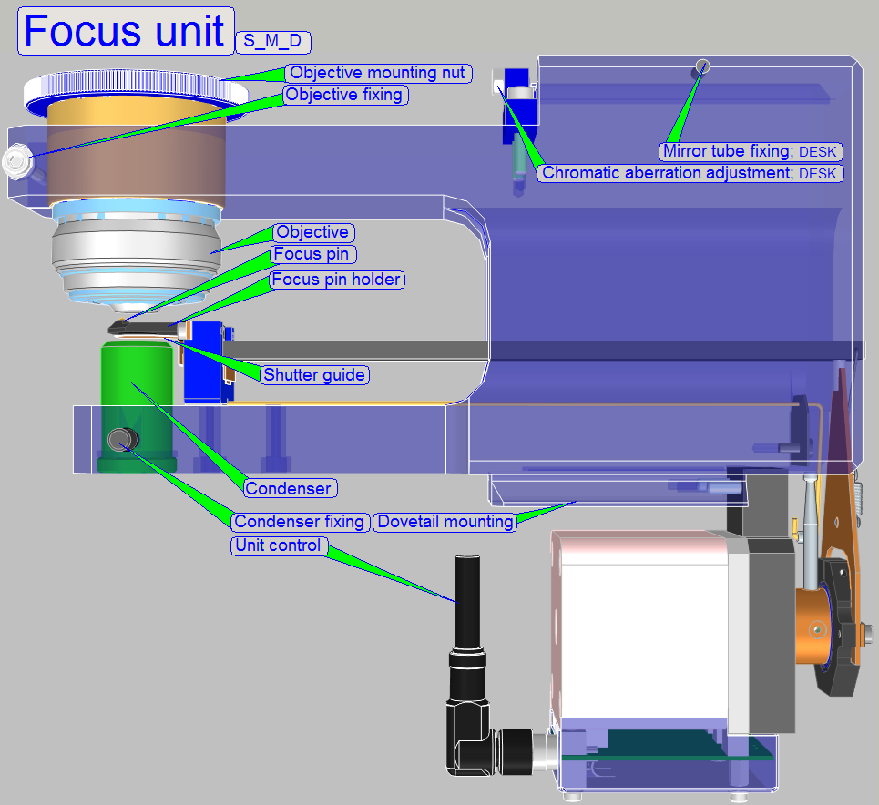
focus unit is a component of the Pannoramic scanner family and contains the following
main parts:
The described
focus unit is a component of the Pannoramic scanner family and contains the following
main parts:
·
The focusing part
(driven by the focus stepper
motor)
·
The
objective with mounting nut and objective position fixing
·
The
condenser with its position fixing
·
The focusing mechanics
(Ex-center, 8:1 divider, Focus pin)
·
The shutter
mechanics (Shutter arm, shutter wire, shutter guide)
The focus unit gives the possibility of
focusing the FOV (field of view, seen by the scan camera) automatically during
the scan process of the sample.
The unit was developed for
the use of objectives
of the following types:
Plan-APOCHROMAT
20x/0.8 and Plan-APOCHROMAT
40x/0.95
The objective type
“Plan-Apochromat” contains several, special chromatically and spherically
corrections and delivers so an image of very high color trueness with very
small spherical aberration.
If the mechanical dimensions
do not exceed the size of the Plan-APOCHROMAT 40x0.95 type objective, the
mechanical mounting is identical and the focus distance of the objective to the
tissue is not closer then 0.25mm, other kind of objectives can be used also but
it is strongly not recommended!
·
Always check with 3DHISTECH first when a different
objective should be used!
The shutter mechanics covers the
condenser and this way, during fluoresce scan sessions, the bright field
illumination path is broken. The two commands, condenser cover off and
condenser cover on are identical with the physical lower and upper limits of
the focus unit.
The
exchange of the focus unit is possible
- If the stepper motor or
its electronics for the focus unit is faulty
 - If the shape of any
part is deformed or a part is broken.
- If the shape of any
part is deformed or a part is broken.
-
If the focus unit has any fault and you
are unable to fix it.
Requirements
- Service
program for Pannoramic scanners (SlideScannerService.exe)
with actual license file
- Pannoramic
Scan Software (version 1.12. or higher) and Pannoramic Viewer software
(SlideScanner.exe, SlideViewer.exe) with actual license files
- 1.5, 2.5, 3 and
- Hardware and construction
knowledge of Pannoramic type scanners
 Attention: Do not mix the versions of SlideScanner.exe
and SlideScannerService.exe! Always use these programs with the same version
number; otherwise the SlideScannerService.exe program could produce unwanted
results and SlideScanner.exe does not work correctly or even freeze!
Attention: Do not mix the versions of SlideScanner.exe
and SlideScannerService.exe! Always use these programs with the same version
number; otherwise the SlideScannerService.exe program could produce unwanted
results and SlideScanner.exe does not work correctly or even freeze!
Focus
unit with objective changer
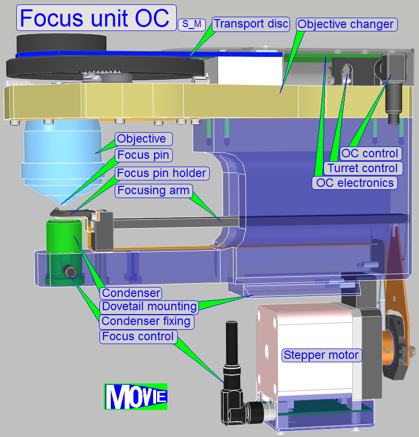 The focus unit with objective changer (Focus unit OC) is a newly developed
component for Pannoramic SCAN and
The focus unit with objective changer (Focus unit OC) is a newly developed
component for Pannoramic SCAN and
The unit is a combination of the
focus part as shown above (Focus unit S_M_D) and this is equipped with the objective changer
unit as used in the P250.
· The unit can be used only in the SCAN and
· Connect the Turret cable of the SCAN or the
· If the scanner is equipped with an objective changer
unit, the name “Modular MIDI” and “Modular SCAN” is used.
Features
The user is able
to use different magnifications consecutively for the brightfield and the
fluorescent scan procedure likewise,
·
Without manual objective exchange.
·
Without additional objective position adjustments.
·
Without additional optical and illumination
adjustments.
· Focusing principle
and unit limits are the same as in the “Focus unit S_M_D”
· Shutter principle
and construction is the same as described for the “Focus unit S_M_D”
·
Exchange of the objective is software controlled and
possible between 2 slide scan sessions.
Once, the objective settings are defined in the dialog “Microscope
Settings” these must not be changed or modified until the objective(s) will
be exchanged physically.
![]() “Objective changer”;
“Configure the scanner”, “Service Program”
“Objective changer”;
“Configure the scanner”, “Service Program”
· For focusing and shutter relevant components and
construction please refer to this description (in front of you)
· For objective change relevant components and
construction please refer to the “Objective changer
part” of the description “Objective
changer for P250”
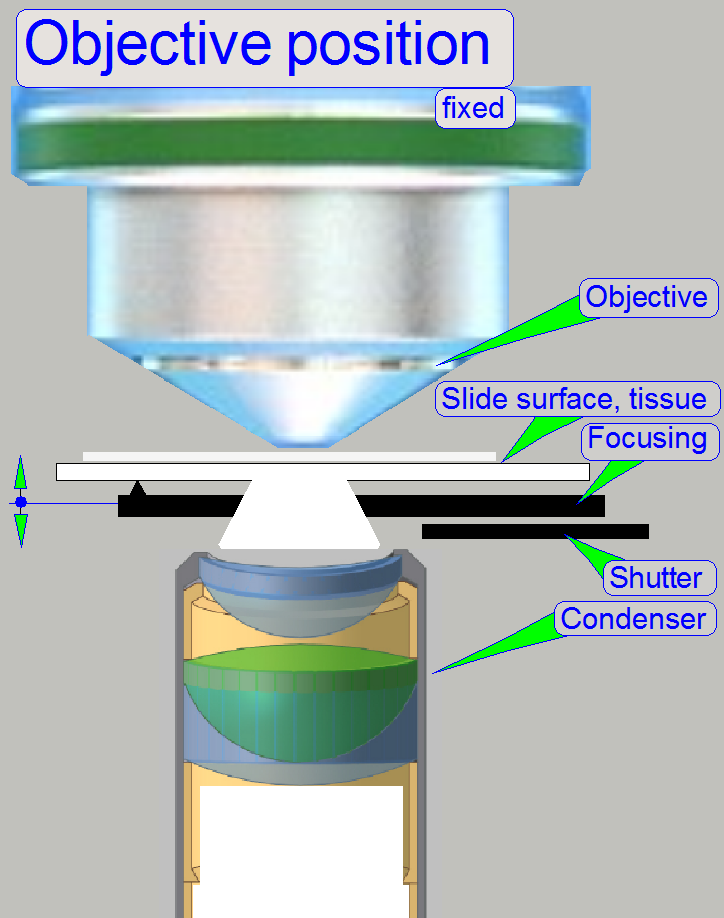
Physically, the focus
position is defined by the distance of the objective to the tissue. If the
tissue is in the focus of the objective, a sharp picture is seen by the camera.
Because the tissues are different from each other in thickness and the
thickness can change inside the same tissue also, the focus position must be
checked and corrected always, during scanning.
Furthermore, if the slide
will be changed, the specimen
holder must be moved away from the objective to avoid collision.
If the shutter is changed from
shutter off to shutter on, the specimen holder is moved to a position where the
focus pin is not in connection with the specimen holder.
During all these actions,
except focusing, the objective must be protected against touching and the focus
pin as well as the 8:1 divider must be protected against overstraining. This is
realized by the focus unit, with the different positions of the focus pin and
the positions of the specimen holder; mounted on the X-Y-stage.
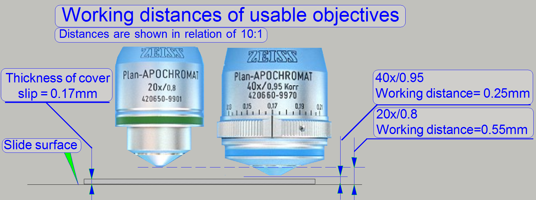 As you can see,
the gaps between cover slip and objective are very small, especially if the
objective Plan-APOCHROMAT
40x/0.95 is used.
As you can see,
the gaps between cover slip and objective are very small, especially if the
objective Plan-APOCHROMAT
40x/0.95 is used.
The worst case for focusing is
defined by the parameters of the 40x objective.
Because the objective in
Pannoramic type scanners is mounted in the nominal focus position, so we have
to move the tissue toward the objective or away from it to find the real focus.
It is very important, that the objective position is adjusted well; otherwise,
if the objective focus position does not match the focus range, offered by the
focus pin movement range, a sharp camera image can never be produced.
![]()
Carl Zeiss GmbH: Plan-APOCHROMAT
20x/0.8 and Plan-APOCHROMAT
40x/0.95
“Objectives from Carl Zeiss” local PDF-file; Product information

On the scale of the 40x
objective, the thickness of the cover slip should be selected. If the real
thickness of the cover slip differs from the selected or adjusted value, the
quality of the scanned FOV may be reduced; resulting in poor contrast and bad
resolution! This may also occur if the thickness of the cover slip is adjusted
correct and the tissue is too thick or the thickness of the tissue varies too
much!
![]() “Spherical aberration” Wikipedia
“Spherical aberration” Wikipedia
 In Pannoramic type
scanners the objective is mounted into the middle of the focus range, offered
by the movement limits of the focus pin during focusing.
In Pannoramic type
scanners the objective is mounted into the middle of the focus range, offered
by the movement limits of the focus pin during focusing.
- It is very important, that the objective
position is adjusted well; otherwise, if the objective position does not match
the focus range, offered by the focus pin movement range, a focused camera
image can never be produced!
- Because the slide thickness can vary from
0.95 to
![]() “Adjust the
objective position”.
“Adjust the
objective position”.
 The slide is hold
in the specimen holder. To achieve a parallel movement of the slide in relation
to the objective, the specimen holding mechanics contains a parallelogram. This
guarantees the position of the tissue to be always perpendicular to the optical
axis. The specimen holder has a mechanical preload, so the slide has always a
connection to the focus pin during scanning.
The slide is hold
in the specimen holder. To achieve a parallel movement of the slide in relation
to the objective, the specimen holding mechanics contains a parallelogram. This
guarantees the position of the tissue to be always perpendicular to the optical
axis. The specimen holder has a mechanical preload, so the slide has always a
connection to the focus pin during scanning.
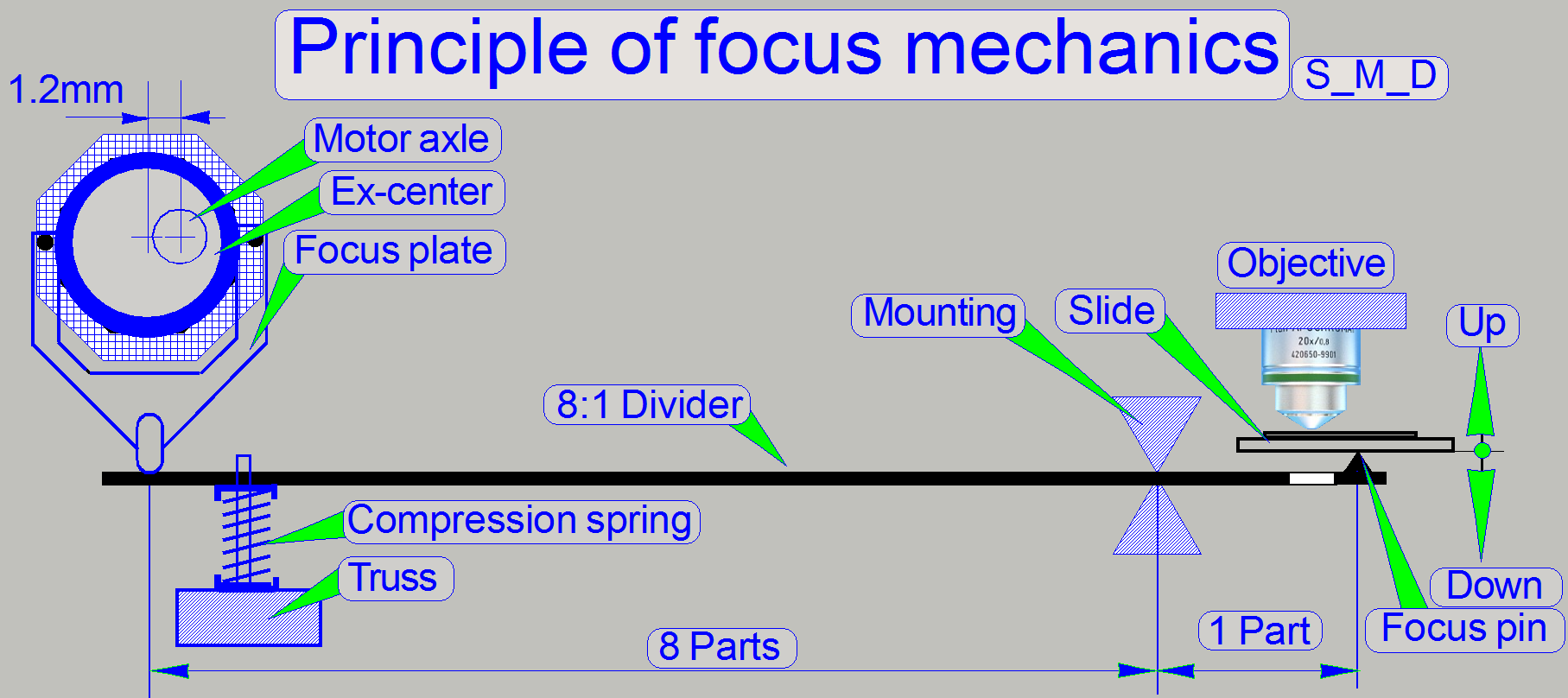
The focus pin is moved by a
stepper motor via an ex-center and an 8:1 divider. The resolution of the
stepper motor with 3200steps per revolution, the characteristics of the
ex-center and the 8:1 divider allows a very fine resolution of the focus steps
and so tissue focusing.
The focus position of the FOV
is found, if the camera sees a sharp image. To reach this, the scan camera
takes images in different positions of the entire focus range and the software
finds the best focus range. When this range is found the real focus position is
found by iteration of the interval.
![]() “Specimen holders”, “Parallelogram”, “Stepper motor”
“Specimen holders”, “Parallelogram”, “Stepper motor”
Home1,2
 The Home position
of the entire mechanics is situated outside the focus range and is always found
within Home1 and Home2. The counting of the ex-center motor steps starts after
a Home1,2 execution.
The Home position
of the entire mechanics is situated outside the focus range and is always found
within Home1 and Home2. The counting of the ex-center motor steps starts after
a Home1,2 execution.
![]() “Stepper motor
implementation”; and “Sensors
Home1,2”
“Stepper motor
implementation”; and “Sensors
Home1,2”
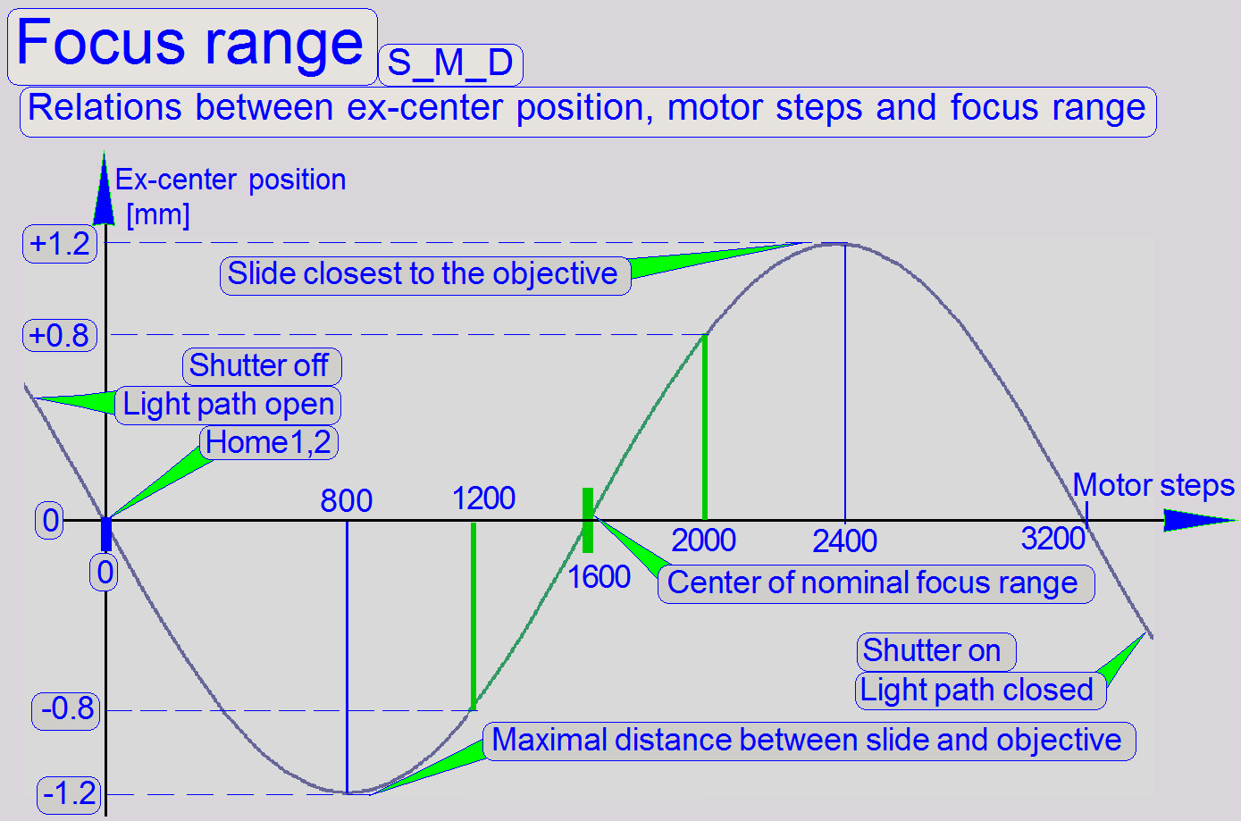
Focus range
The step number of the
stepper motor is identical with the actual focus position and this is displayed
by the software. The entire focus range in S_M_D scanners is 800 steps, counted
from 1200 to 2000. Its true, that the focus of the tissue is reached at the
positions Home1,2, 1600 steps and 3200 steps, but the center of the nominal
focus range is defined at the position 1600 steps.
![]() “Hardware limits and
shutter on or off”
“Hardware limits and
shutter on or off”
|
Pre-calculated values for slide thicknesses |
|
|
Slide thickness [mm] |
Focus position [steps] |
|
1.05 |
1350 |
|
1.00 |
1600 |
|
0.95 |
1850 |
Because the specimen holder
of S_M_D type scanners can hold slides with a thickness of 0.95 to
- Measure the thickness of the slide (but
without the cover slip) with tissue to be used; use the caliper.
·
If the thickness of the slide deviates from 1.00mm, calculate
the focus position. A deviation in thickness of 0.01mm results in a deviation
of 50 motor steps.
·
Insert the measured slide into the specimen holder and
set the appropriate (calculated) focus position in the live view of the program
SlideScanner.exe.
·
Adjust the objective position to the preset focus
position until a focused image can be seen in the live view.
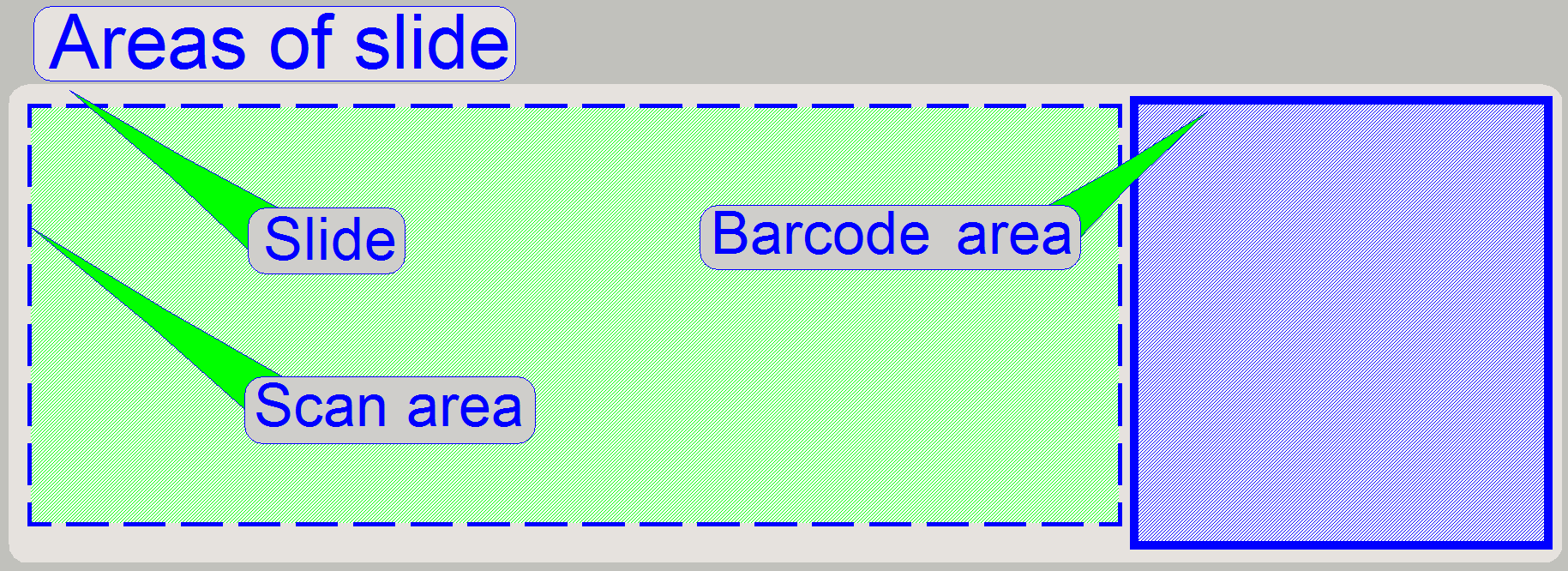 The scan area defines the part of the slide on which
the tissue, scanned by the scan camera, is expected to be. The entire scan area
is captured by the preview camera in three sections and is shown in the preview
area of the program SlideScanner.exe.
The scan area defines the part of the slide on which
the tissue, scanned by the scan camera, is expected to be. The entire scan area
is captured by the preview camera in three sections and is shown in the preview
area of the program SlideScanner.exe.
The scan area is limited by the
mechanical construction of the specimen holder and should be defined as large
as possible; it is not defined in relation to the cover slip.
In all cases, the specimen holder
should never be touched by the focus pin or the objective! In other words, the
scan area is that area of the slide, on which the focus pin and the objective
(especially 40x magnification) can be moved seemingly during scanning the
tissues, without touching the specimen holder.
As mentioned before, the focus unit
may be equipped with a 20x or a 40x objective. Because the focus position of
the 40x objective is very close to the tissue, the scan area, defined for the
20x objective is no longer valid, to avoid collision of the objective with the
specimen holder.
If the objective will be changed
from a 20x to a 40x magnification, the scan area must be defined again and
therefore the preview calibration must be executed again also. During defining
the scan area for the 40x objective, the position of the focus pin and the position of the objective pupil
should be checked to avoid touching of the specimen holder! Adjust the limits
in the nominal focus position!
If the objective is changed from the
40x to a 20x magnification it is not bound to define the scan area again,
if the smaller area can be accepted. In
all cases, if the scan area was modified, a preview calibration is bound to do.
![]() “Working distances” and “How to exchange the
objective in SCAN, MIDI and DESK”
“Working distances” and “How to exchange the
objective in SCAN, MIDI and DESK”
Physical construction of the specimen holders
Because the physical holding of the
slide is different in all three scanner types, the scan area values are
different also and they vary from scanner to scanner of the same type also
(mechanical tolerances).
In all cases, the scan area values of X-min, X-max, Y-min and Y-max are
set just before the focus pin or the objective touches the specimen holder. The
accuracy of the limits is 100 steps.
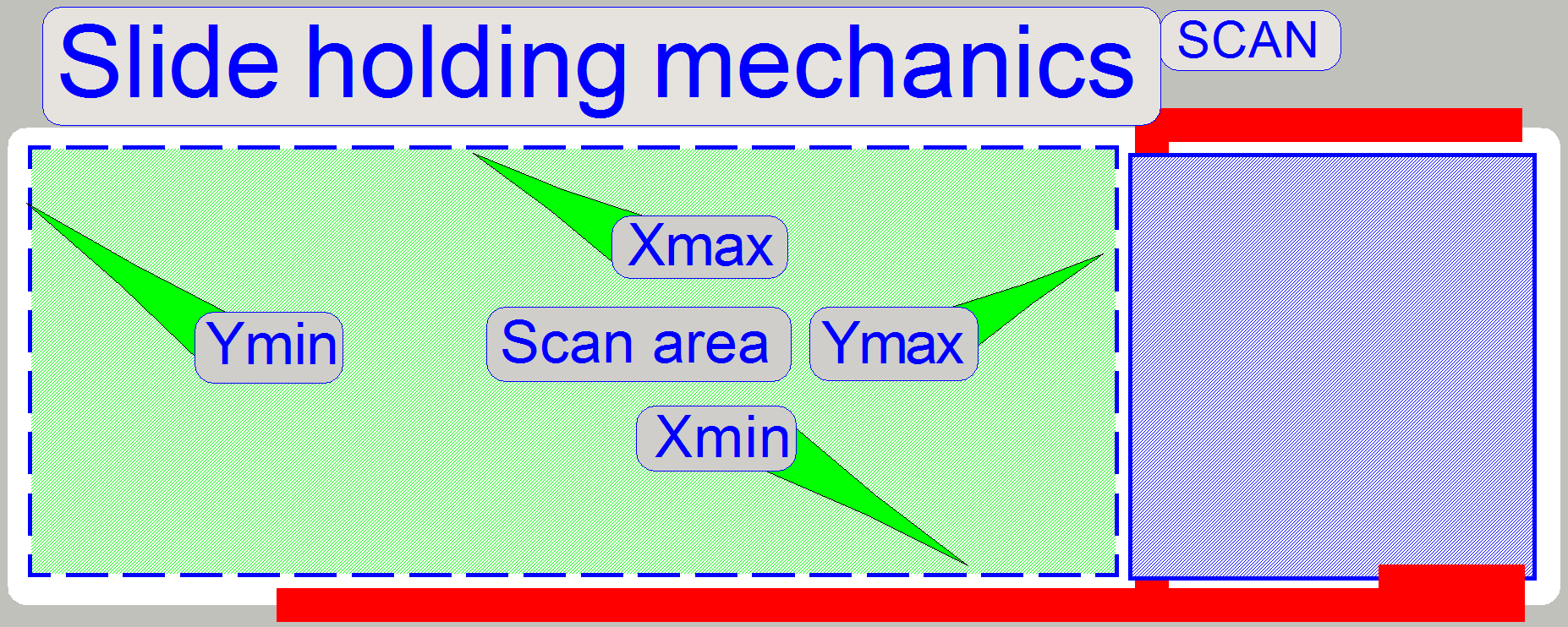
Pannoramic SCAN
 The slide is hold by the specimen holder on the
longer, lower edge and with a slide clamp on its upper edge, on the barcode
area; see the red lines on the right. As you can see, the definition of the
limits X-min and Y-max are critical. X-max and Y-min are given by the maximal
usable slide size and are not critical; they could be the slide edge.
The slide is hold by the specimen holder on the
longer, lower edge and with a slide clamp on its upper edge, on the barcode
area; see the red lines on the right. As you can see, the definition of the
limits X-min and Y-max are critical. X-max and Y-min are given by the maximal
usable slide size and are not critical; they could be the slide edge.
![]() “Specimen holder”, “Areas of the slide”, “Scan area” and “Define the scan area”
“Specimen holder”, “Areas of the slide”, “Scan area” and “Define the scan area”
Pannoramic
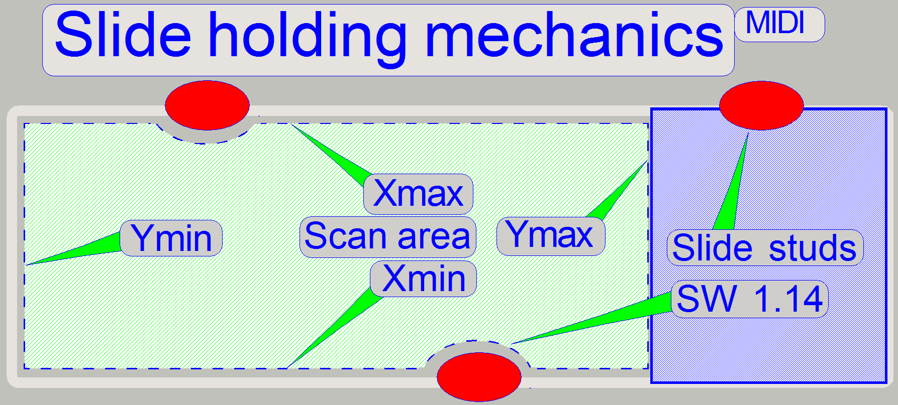 The slide is hold in the specimen holder with the help
of three slide studs, situated on the longer edges as shown.
The slide is hold in the specimen holder with the help
of three slide studs, situated on the longer edges as shown.
The surrounding of the slide stud is
left out automatically from the scan process since the software version 1.14
and needs not to be excluded manually from the scan area.
IMPORTANT
· Never cross the slide stud with the focus
pin or the objective!
![]() “Specimen holder”, “Areas of the slide”, “Scan area” and “Define the scan area”
“Specimen holder”, “Areas of the slide”, “Scan area” and “Define the scan area”
Pannoramic DESK
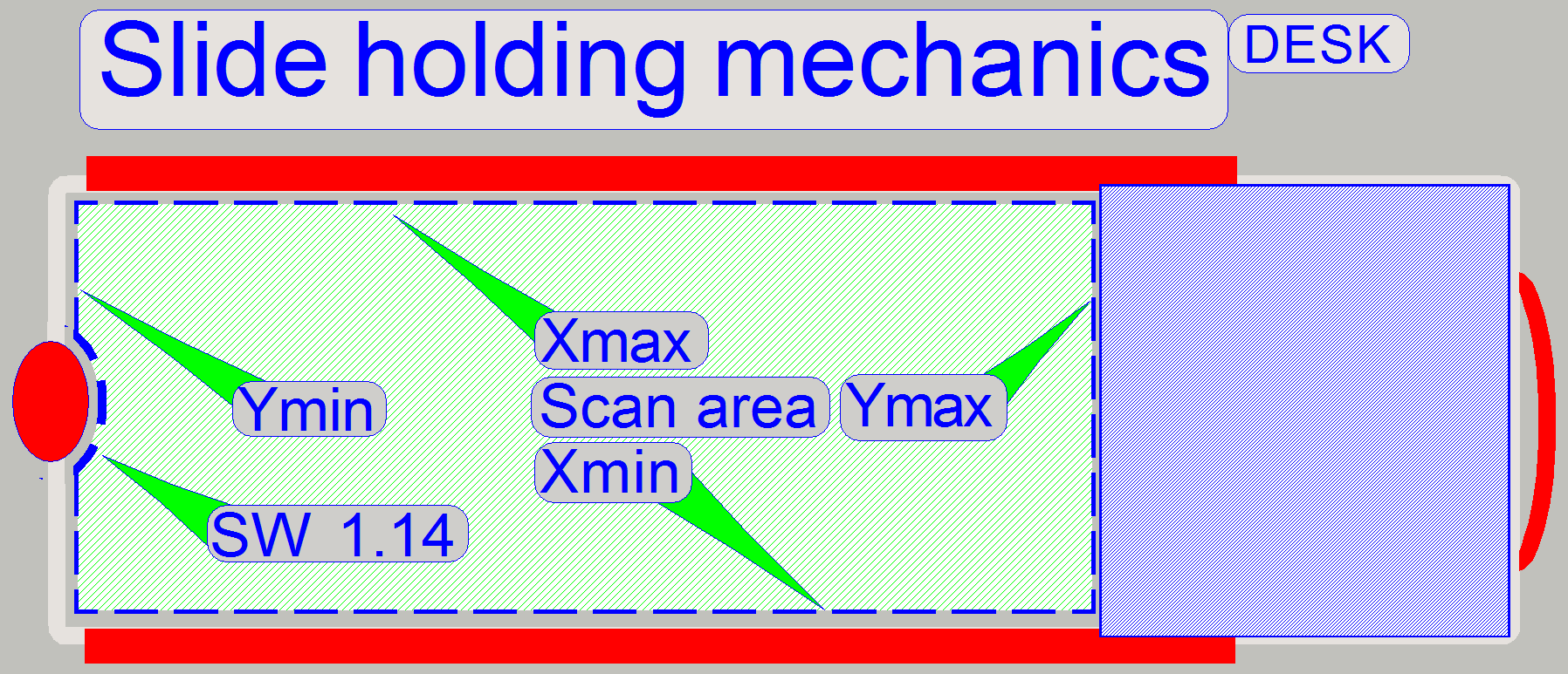 The slide is hold in the specimen holder by the help of
one slide stud on the shorter, inner edge and by the lock handle on the outer,
shorter edge. Furthermore, along the longer edges of the slide there are
leading rails situated to lead the slide during slide insertion. All this facts
should be taken into account if the scan area is defined. The surrounding of
the slide stud is left out automatically from the scan process since the
software version 1.14 and needs not to be excluded manually from the scan area.
If you are working with the service program take care of the focus pin and the
objective.
The slide is hold in the specimen holder by the help of
one slide stud on the shorter, inner edge and by the lock handle on the outer,
shorter edge. Furthermore, along the longer edges of the slide there are
leading rails situated to lead the slide during slide insertion. All this facts
should be taken into account if the scan area is defined. The surrounding of
the slide stud is left out automatically from the scan process since the
software version 1.14 and needs not to be excluded manually from the scan area.
If you are working with the service program take care of the focus pin and the
objective.
IMPORTANT
· Never cross the slide stud with the focus
pin or the objective!
![]() “Specimen holder”, “Areas of the slide”, “Scan area” and “Define the scan area”
“Specimen holder”, “Areas of the slide”, “Scan area” and “Define the scan area”
·
Since the software version 1.18 the MIDI OC and SCAN
OC scanners are requiring configuration parameters.
Modular MIDI; (
[Microscope]; Modular
SerialNumber=PMIDI-032101; Serial
number of the scanner
MicroscopeType=3DMic10;
ScanCameraType=Hitachi_HV_F22CL; not
used, not defined here
PreviewCameraType=CVrmc_m8_pPro;
Preview
camera type
BarcodeReaderType=PreviewCamera; Barcode
capturing is done by the preview camera
LoaderType=SL_1Mag_12Slide_Sensor_Horizontal; Slides are hold in the
tray with 12 bays and slide sensor used
CameraChangerType=CC_None; Camera_chancher_VT
not present
ReflectorTurretType=RT_3DH_10Pos_Gears; Gear driven RTU present
BrightfieldLightSourceType=BLS_Halogen_5W; FOV Brightfield illumination
done by a 5W halogen lamp
ObjectiveChangerType=OC_2Pos; Objective
changer type with 2 objective positions present
ObjectGuideXYZType=OGXYZ_1.0mm; The specimen
holder can hold slides with a thickness of 1.0mm nominal
FlashUnitType=NoFlashUnit Flash
illumination unit not present
NDFilterType=ND_None; ND
filter unit not present
PreviewLightType=PreviewLightUnitType_Type3; Preview illumination BF only
PowerSwitchBoardType=PowerSwitchBoard_None; Power distribution and switch
electronics not present
Following sections and parameters are also implemented
[Focus]NoFocusPinOnTheObjectHolderX=26000NoFocusPinOnTheObjectHolderY=18000
[ObjectiveChanger]ObjectiveChangerTimeout=7000
![]() If
If
“Handling
the *.ini files”; “Service
Program”
Modular SCAN; (SCAN OC)
![]() “Configure the magazine unit” and “Magnet disc”
“Configure the magazine unit” and “Magnet disc”
[Microscope]; MicroscopeType=3DMic11; Modular SCANLoaderType=SL_6Mag_25Slide_NoSensor_Vertical_2; Magazine unit CameraChangerType=CC_NoneReflectorTurretType=RT_3DH_10Pos_GearsBrightfieldLightSourceType=BLS_Halogen_5WObjectiveChangerType=OC_2PosObjectGuideXYZType=OGXYZ_1.0mmFlashUnitType=NoFlashUnitNDFilterType=ND_NonePreviewLightType=PreviewLightUnitType_Type3PowerSwitchBoardType=PowerSwitchBoard_None
Following sections and parameters are also
implemented!
[Focus]NoFocusPinOnTheObjectHolderX=29600NoFocusPinOnTheObjectHolderY=18000
[ObjectiveChanger]ObjectiveChangerTimeout=7000
![]() If SCAN OC: “MicroscopeConfiguration.txt”
If SCAN OC: “MicroscopeConfiguration.txt”
“Handling the *.ini files”; “Service Program”
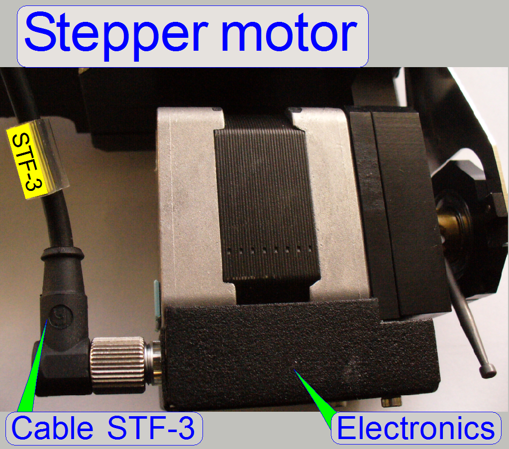
The drive of the focus unit is
realized with a 2-phase stepper motor and has a resolution of 3200µ-steps/revolution
and drives:
·
the focusing part via the ex-center, the 8:1 divider
and the focus pin (see “Principle
of focusing”) and
·
the shutter guide via the shutter arm and the shutter
wire (see “Principle
of shutter mechanics”).
The forward direction of the
motor’s axle is counter clock wise, CCW . The command and status information
for the focus unit like step number and direction; go to Home1,2 or go to
shutter on or shutter off are received from the stepper motor’s electronics via
the cable STX-3
(X stands for the actual hardware version and depends on the scanner type
also).
· The address of the
focus motor in S_M_D is always 05.
· The parts and
units of the stepper motors need neither maintenance nor mechanical adjustments.
![]() “Stepper motor”, “Addresses”, “Cabling of addressable
units” and “USB-controller
cabling”
“Stepper motor”, “Addresses”, “Cabling of addressable
units” and “USB-controller
cabling”
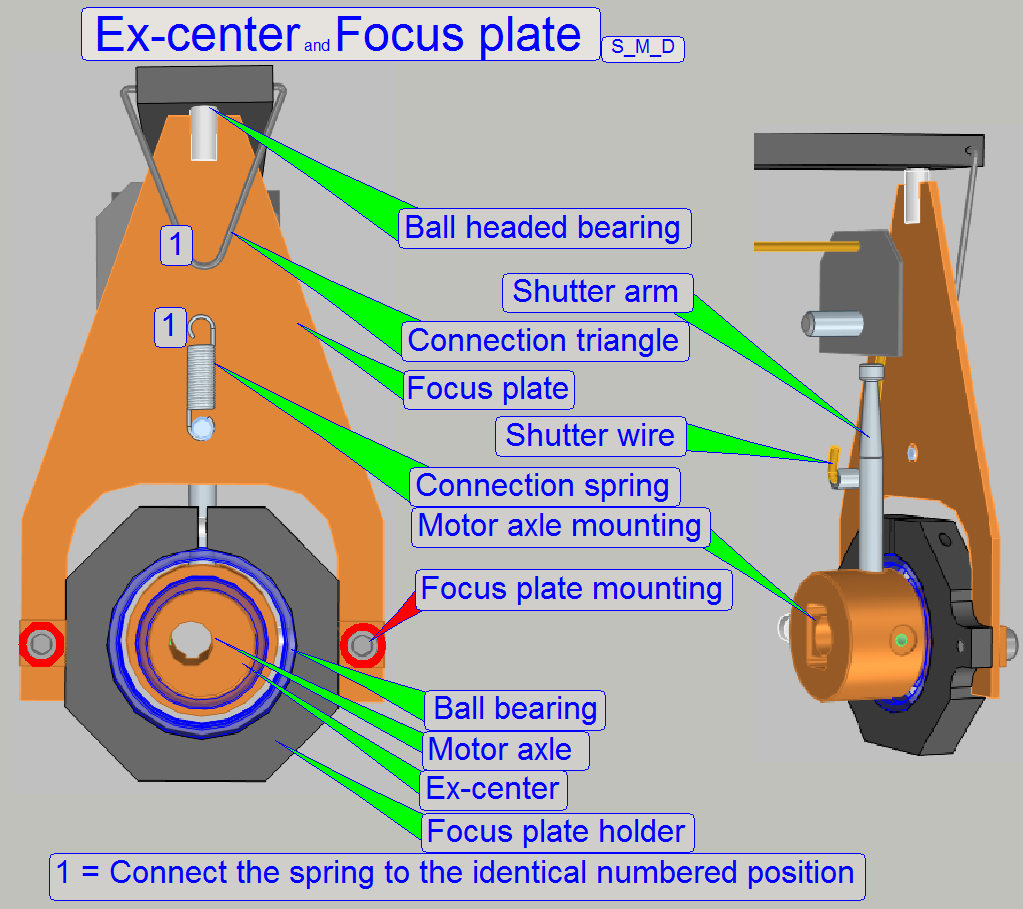 The motor axle of the
stepper motor rotates the ex-center on which the focus plate is mounted and
this moves the 8:1 divider.
The motor axle of the
stepper motor rotates the ex-center on which the focus plate is mounted and
this moves the 8:1 divider.
·
The ex-center position is correct, if 1600 focus steps
are moved and the shutter arm stays in the middle of the slot. If this
condition is not met, please adjust the ex-center position more precise
(maximal tolerance is 10steps).
Attention
The mountings of the focus
plate should not be loosened; here the position of the focus plate and so the
position of the 8:1 divider and the position of the focus pin is adjusted!
Because the movement range of
the focus pin is very small, the adjustment of the focus pin position is
delicate; the focus plate mounting bolts
position must not be altered.
·
The adjustment of the focus pin position requires special adjustment
tools!
 Furthermore, on
the ex-center mounting the shutter arm is situated for the shutter off and on
operation. This defines in the same time, together with the shutter wire the
hardware limit for the focus unit.
Furthermore, on
the ex-center mounting the shutter arm is situated for the shutter off and on
operation. This defines in the same time, together with the shutter wire the
hardware limit for the focus unit.
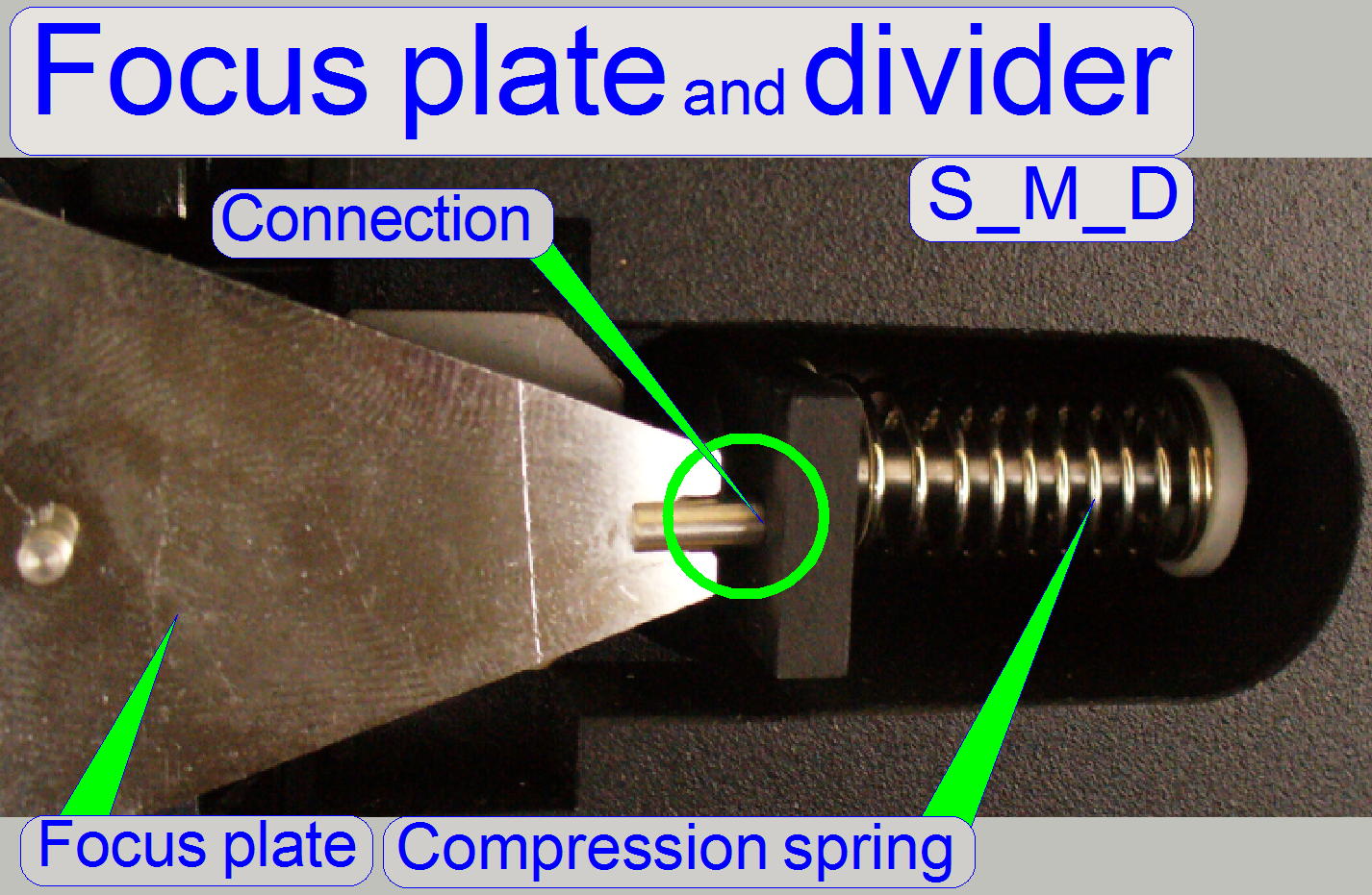
The connection between focus
plate and divider is realized with a ball-headed joining because the ex-center
does an up-down and additionally a left-right movement.
·
The use of the compression spring ensures a
hysteresis-free connection.
·
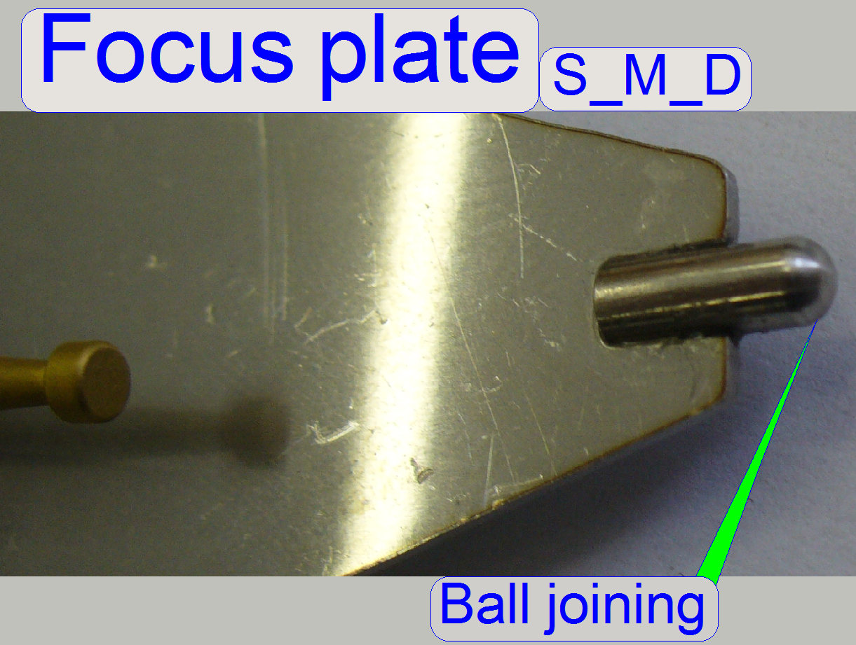 The bearing of the
8:1 divider and the ball-headed pin of the focus plate eliminates the unwanted
left and right movement.
The bearing of the
8:1 divider and the ball-headed pin of the focus plate eliminates the unwanted
left and right movement.
8:1 divider and focus pin
 On the other end
of the 8:1 divider the focus pin is realized. The focusing of the tissue is
done by moving the focus pin (and so the tissue) toward or away from the
objective. Because the focus pin touches the slide always during focusing, the
distance of the slide with tissue to the objective is modified until the focus
position is found. The mechanical construction allows a focus pin movement of
On the other end
of the 8:1 divider the focus pin is realized. The focusing of the tissue is
done by moving the focus pin (and so the tissue) toward or away from the
objective. Because the focus pin touches the slide always during focusing, the
distance of the slide with tissue to the objective is modified until the focus
position is found. The mechanical construction allows a focus pin movement of
 Adjust the
objective position so that the tissue is in focus while the nominal software focus
position is selected by the software (1600 focus steps).
Adjust the
objective position so that the tissue is in focus while the nominal software focus
position is selected by the software (1600 focus steps).
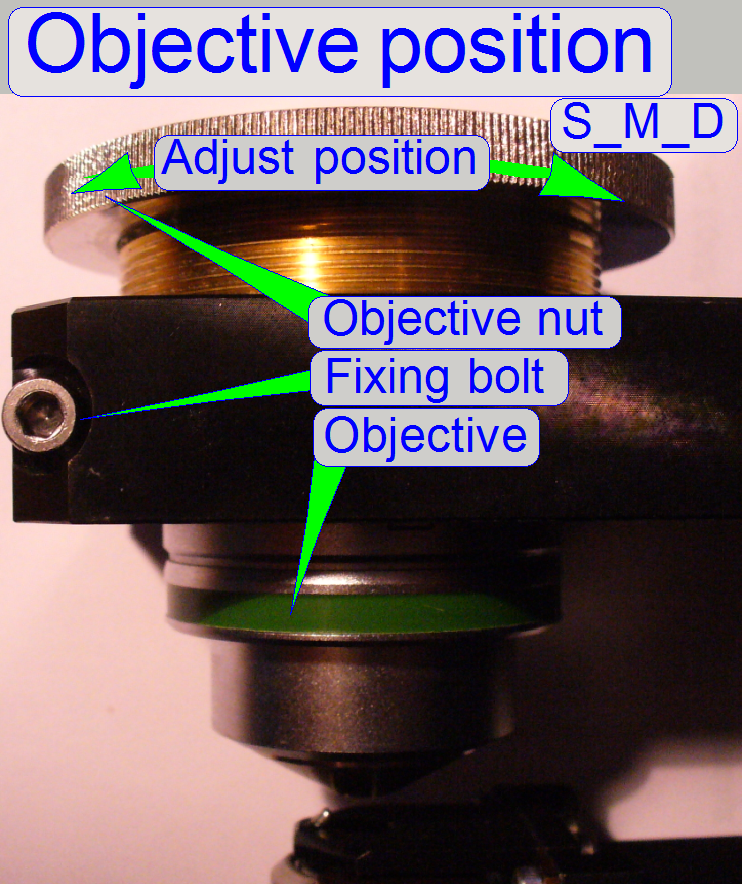
·
The objective
nut can be screwed if the fixing bolt is loosened.
· To mount or
exchange the objective, remove the objective nut, mount or exchange the
objective, insert the objective nut again and adjust the objective position!
· By rotating the
objective nut with barely loosened fixing bolt the objective position will be
modified and so adjusted.
· Tighten the fixing
bolt so, that the position of the knurled objective nut can even not be modified
manually.
·
To exchange the
objective, please refer to the appropriate chapter in the folder “How to exchange …”
![]() “Working distances” and “Exchange the objective SCAN, MIDI, DESK”
“Working distances” and “Exchange the objective SCAN, MIDI, DESK”
Carl Zeiss GmbH: Plan-APOCHROMAT
20x/0.8 and Plan-APOCHROMAT
40x/0.95
“Objectives from Carl Zeiss” ©Carl ZEISS GmbH; stored PDF-file;
Product information
·  The image path cover
tube exists in two versions; depending on the existence of the turret unit,
whether the shorter or the longer tube is used.
The image path cover
tube exists in two versions; depending on the existence of the turret unit,
whether the shorter or the longer tube is used.
· The shorter cover
tube is mounted directly onto the objective nut, in opposite of the objective.
· The longer cover
tube is used if the turret unit is not implemented and is mounted into the camera tube
mounting; on the opposite side of the camera tube.
· The image path
cover tube is used in the SCAN and the
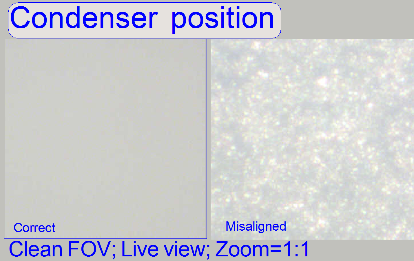
The condenser concentrates
the incoming light to the field of view (FOV).
Because the size of the illuminated part of the tissue is critical, the
condenser position can be adjusted; the focus position is 10.9mm nominal.
![]() Condenser Wikipedia
Condenser Wikipedia
condenser position
adjustment.
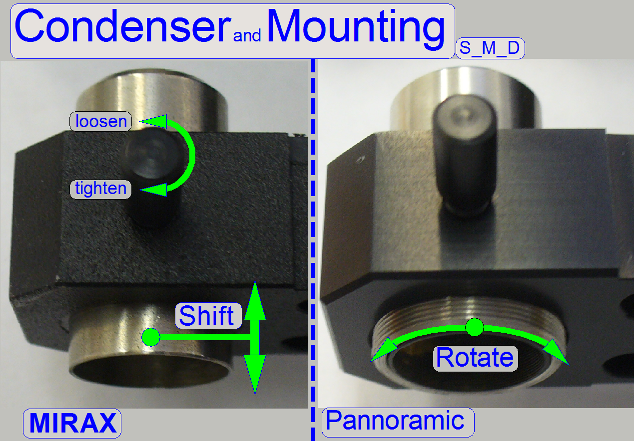 In early developed
scanners (MIRAX SCAN), the condenser position was adjusted by shifting it
toward or away from the tissue, so the correct condenser position could be
found.
In early developed
scanners (MIRAX SCAN), the condenser position was adjusted by shifting it
toward or away from the tissue, so the correct condenser position could be
found.
Because in the SCAN the
condenser is arranged in horizontal position, it is an acceptable and cost-effective
solution.
In the DESK and the
To resolve this problem, the
condenser got a thread part. The early developed version can be found in
scanners, delivered until the end of the year 2009.
Important
·
If an early developed solution is used in the DESK or
the
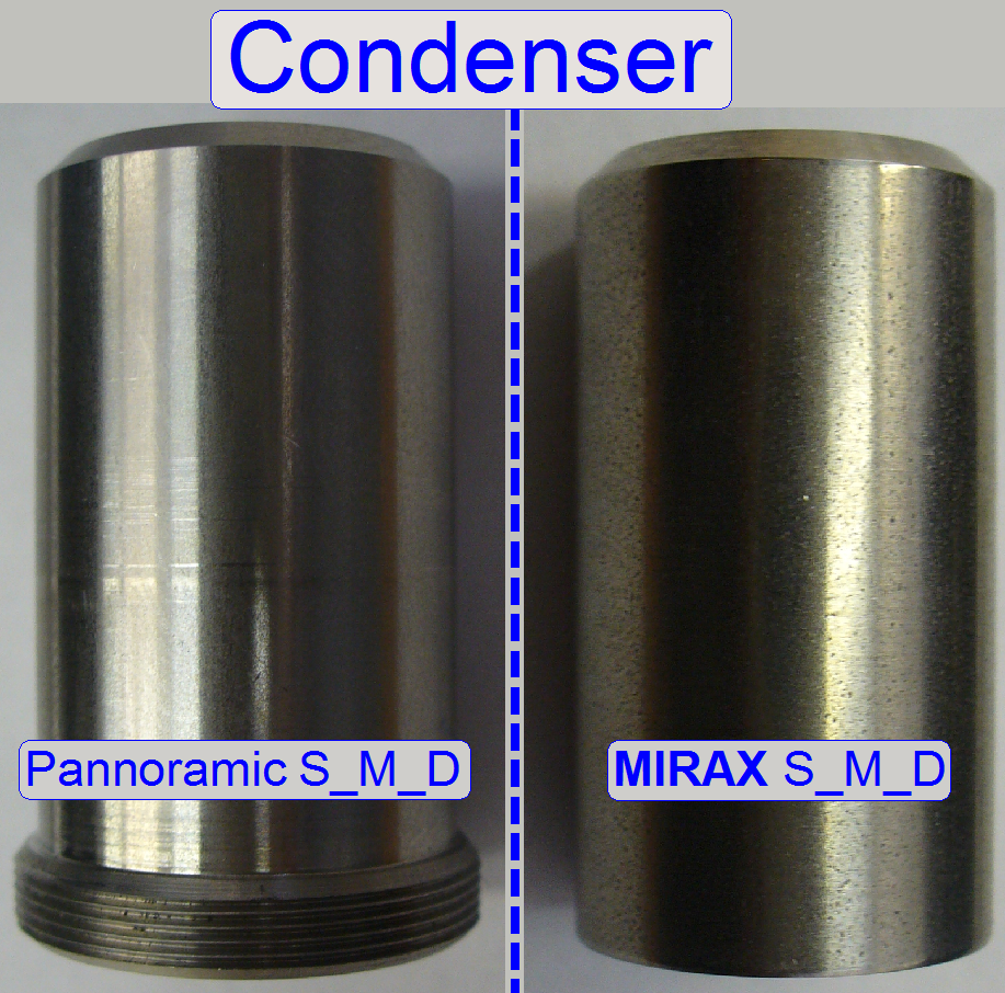
·
The condensers are both from the same type; there are
no differences in the construction of the optics.
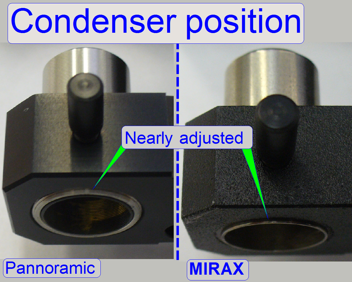
·
In the adjusted condenser position, the condenser
housing looks only a little bit over the mounting.
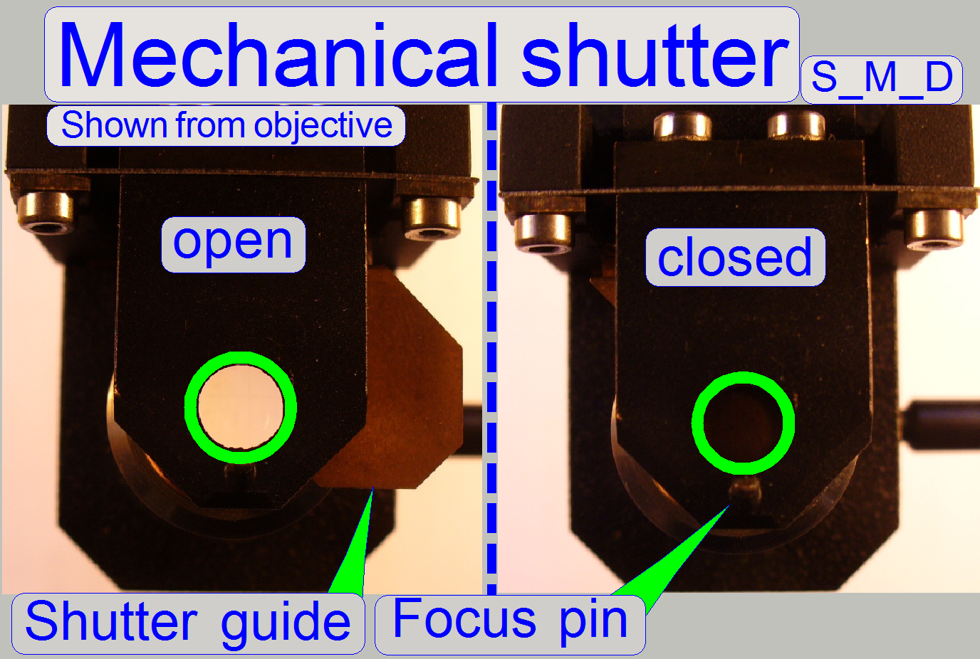
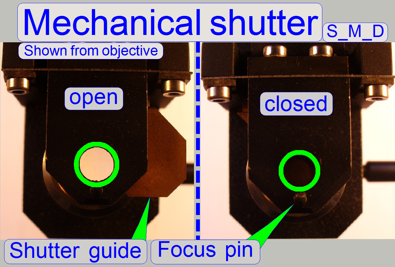 The mechanical shutter is implemented as a part of the
focus unit and the shutter guide is situated between condenser and 8:1 divider.
The mechanical shutter is implemented as a part of the
focus unit and the shutter guide is situated between condenser and 8:1 divider.
During fluorescent scan the shutter
must be closed and insures so a dark background. Other, unwanted fluorescent
materials (e.g. painting, optics) can not reflect the fluorescent light or can
not fluoresce and so they will not disturb the fluorescent view.
During bright field illumination the
shutter must be fully open to ensure a bright and evenly illumination of the
FOV.
Principle of shutter mechanics
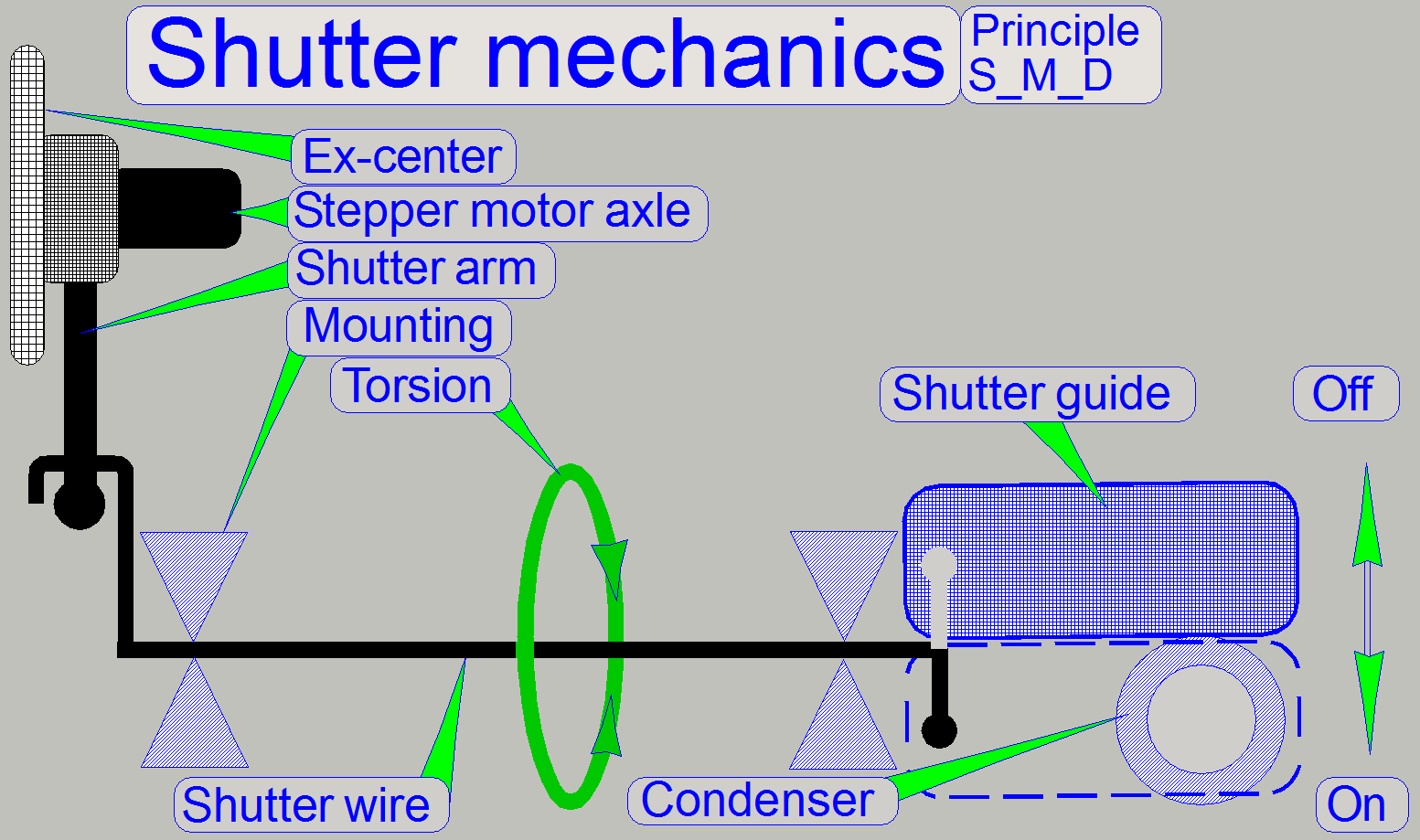 The shutter has
only two usable states, shutter on and shutter off. These positions are
identical with the hardware limits of the focus unit; in these positions the
bright field illumination (the condenser) should be fully opened or fully
closed respectively. All other possible positions of the shutter are not
defined, therefore faulty positions and not allowed during the scan process.
The shutter has
only two usable states, shutter on and shutter off. These positions are
identical with the hardware limits of the focus unit; in these positions the
bright field illumination (the condenser) should be fully opened or fully
closed respectively. All other possible positions of the shutter are not
defined, therefore faulty positions and not allowed during the scan process.
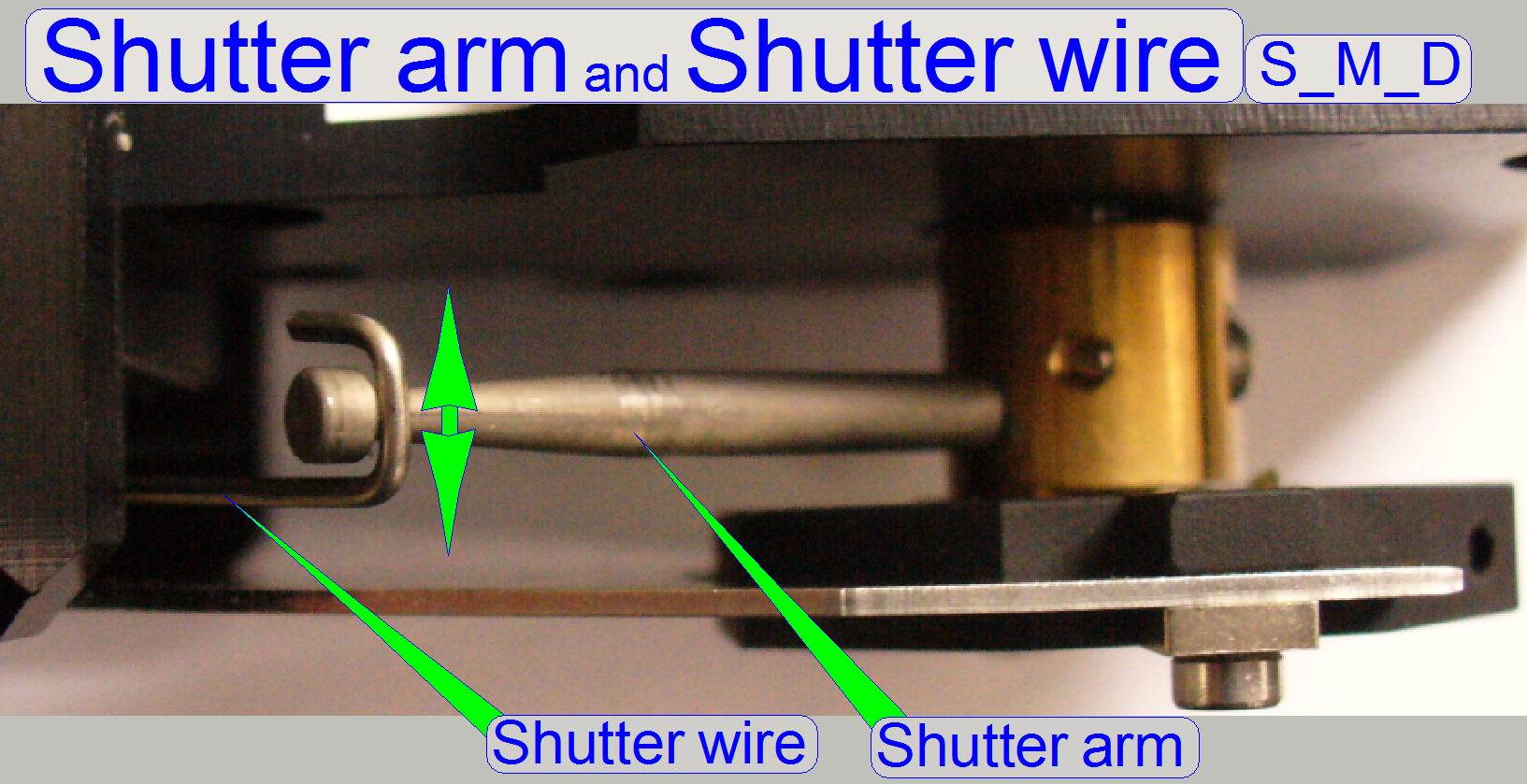
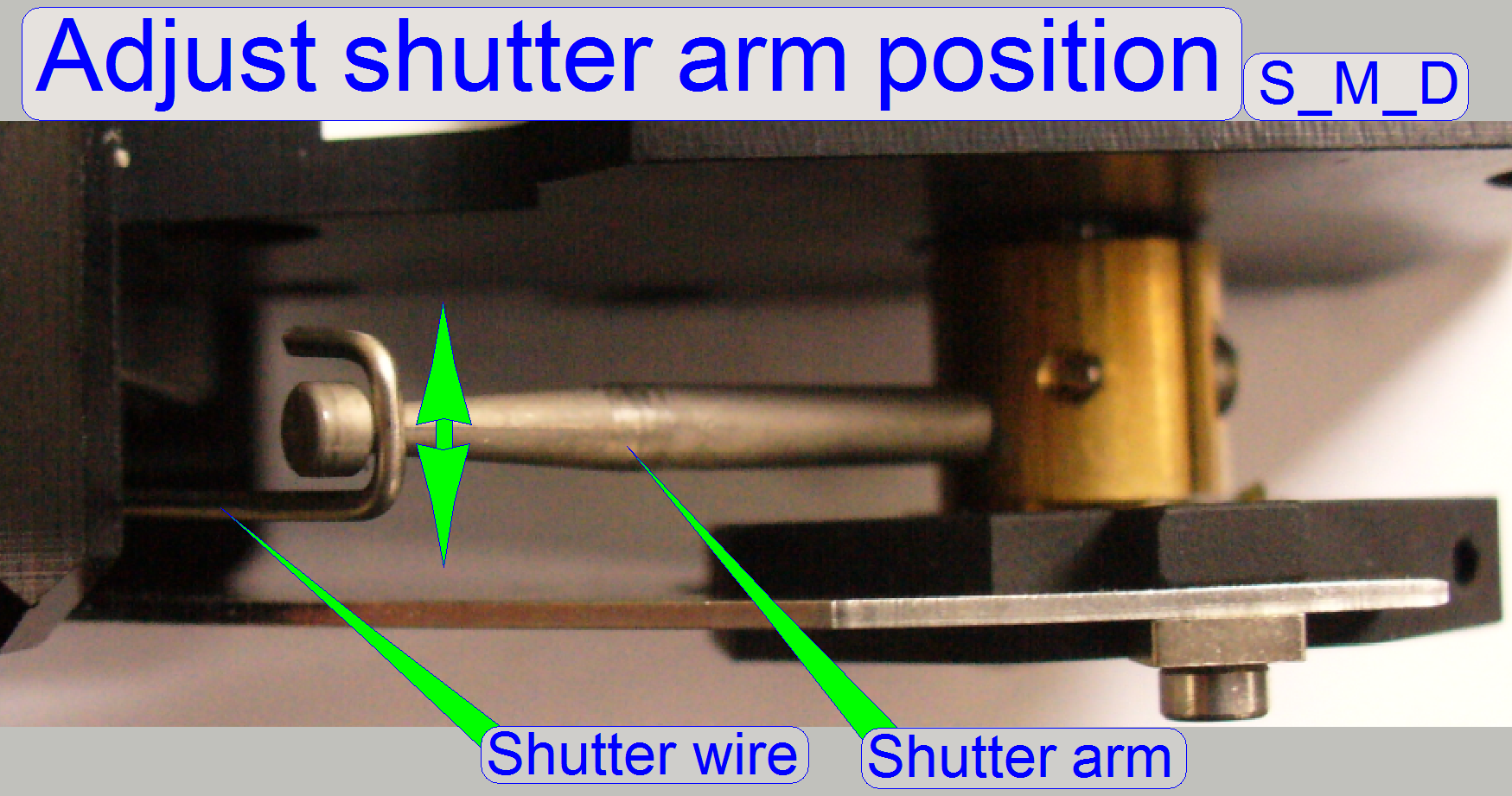
 During rotation of
the stepper motor axle in direction to the negative limit of the focus unit,
the shutter wire will be touched by the shutter arm and is so moved to the shutter
off state (bright field illumination allowed). If the stepper motor axle is
rotated in direction to the positive limit, the shutter arm will touch the
shutter wire from the opposite direction and moves it so to the shutter on
position (bright field illumination disabled).
During rotation of
the stepper motor axle in direction to the negative limit of the focus unit,
the shutter wire will be touched by the shutter arm and is so moved to the shutter
off state (bright field illumination allowed). If the stepper motor axle is
rotated in direction to the positive limit, the shutter arm will touch the
shutter wire from the opposite direction and moves it so to the shutter on
position (bright field illumination disabled).
In practice it means, that
the shutter wire together with the shutter arm is the limiter of the focus
mechanics and with this limiter the shutter on and shutter off option is
realized.
·
During focusing the shutter wire will never be touched
by the shutter arm.
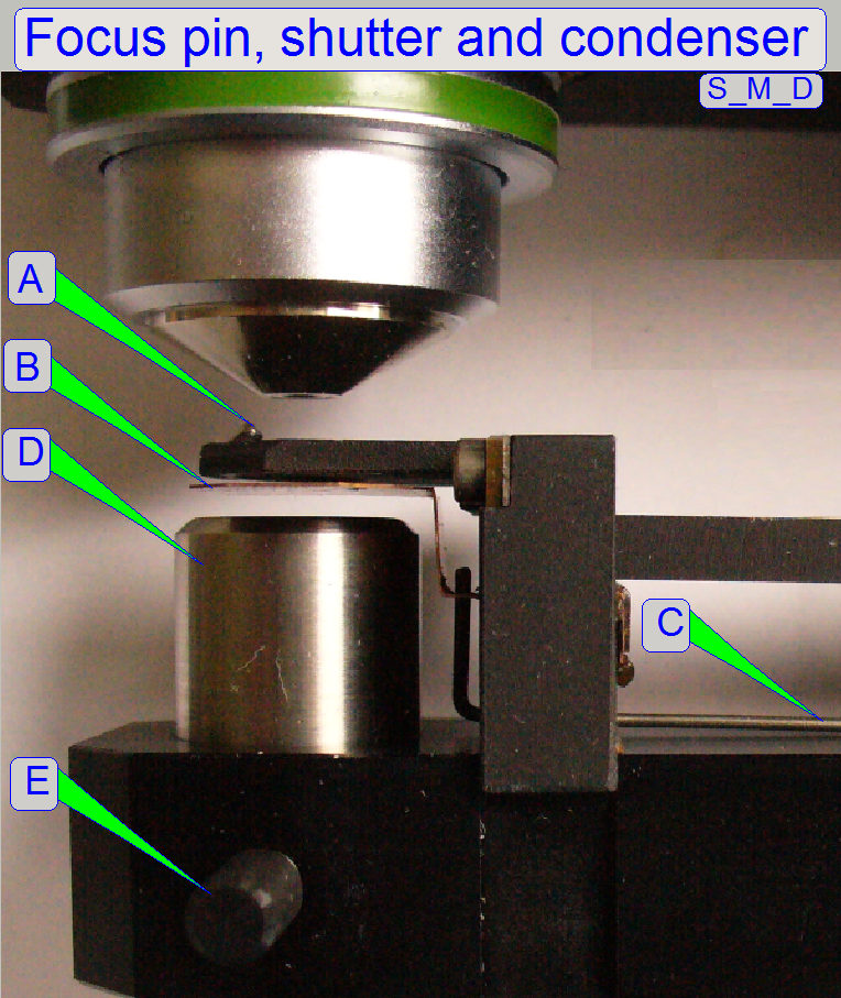
A = Focus
pin
B = Shutter guide
C = Shutter wire
D = Condenser
E = Condenser fixing
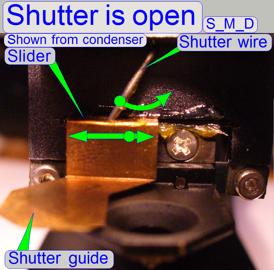 If the shutter wire
is touched by the shutter arm, the torsion is transmitted via the shutter wire
to the slider of the shutter guide. The slider brings so the shutter guide into
the proper position.
If the shutter wire
is touched by the shutter arm, the torsion is transmitted via the shutter wire
to the slider of the shutter guide. The slider brings so the shutter guide into
the proper position.
Shutter on or off and hardware limits
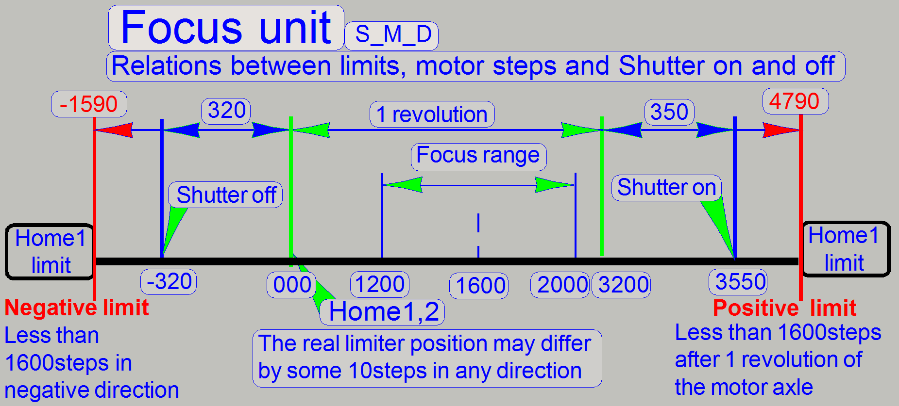 The hardware
limits will be reached only during shutter on (CondenserCoverOn = Light path
closed; fluoresce scan) or the shutter off (CondenserCoverOff = Light path
opened; bright field scan) procedure. The limits are defined without lost
steps; they may differ by some ten steps from unit to unit, the reason is the
tolerances of the components and the found ex-center position in relation to
the motor axle.
The hardware
limits will be reached only during shutter on (CondenserCoverOn = Light path
closed; fluoresce scan) or the shutter off (CondenserCoverOff = Light path
opened; bright field scan) procedure. The limits are defined without lost
steps; they may differ by some ten steps from unit to unit, the reason is the
tolerances of the components and the found ex-center position in relation to
the motor axle.
![]() “How to define hardware limits”
and “Find the hardware
limits for the focus unit”
“How to define hardware limits”
and “Find the hardware
limits for the focus unit”
The following procedures are
described especially for Pannoramic SCAN. In Pannoramic MIDI and Pannoramic
DESK the adjustments are logically identical, but some terms like “up, down,
top, bottom, left, right, horizontal and vertical” differ. Please take this
into account if you are adjusting the DESK or the
 This adjustment
must be done only if the ex-center was dismounted or the fixing bolt was
loosened. With this adjustment the focus position is set to be +1600 steps
nominal.
This adjustment
must be done only if the ex-center was dismounted or the fixing bolt was
loosened. With this adjustment the focus position is set to be +1600 steps
nominal.
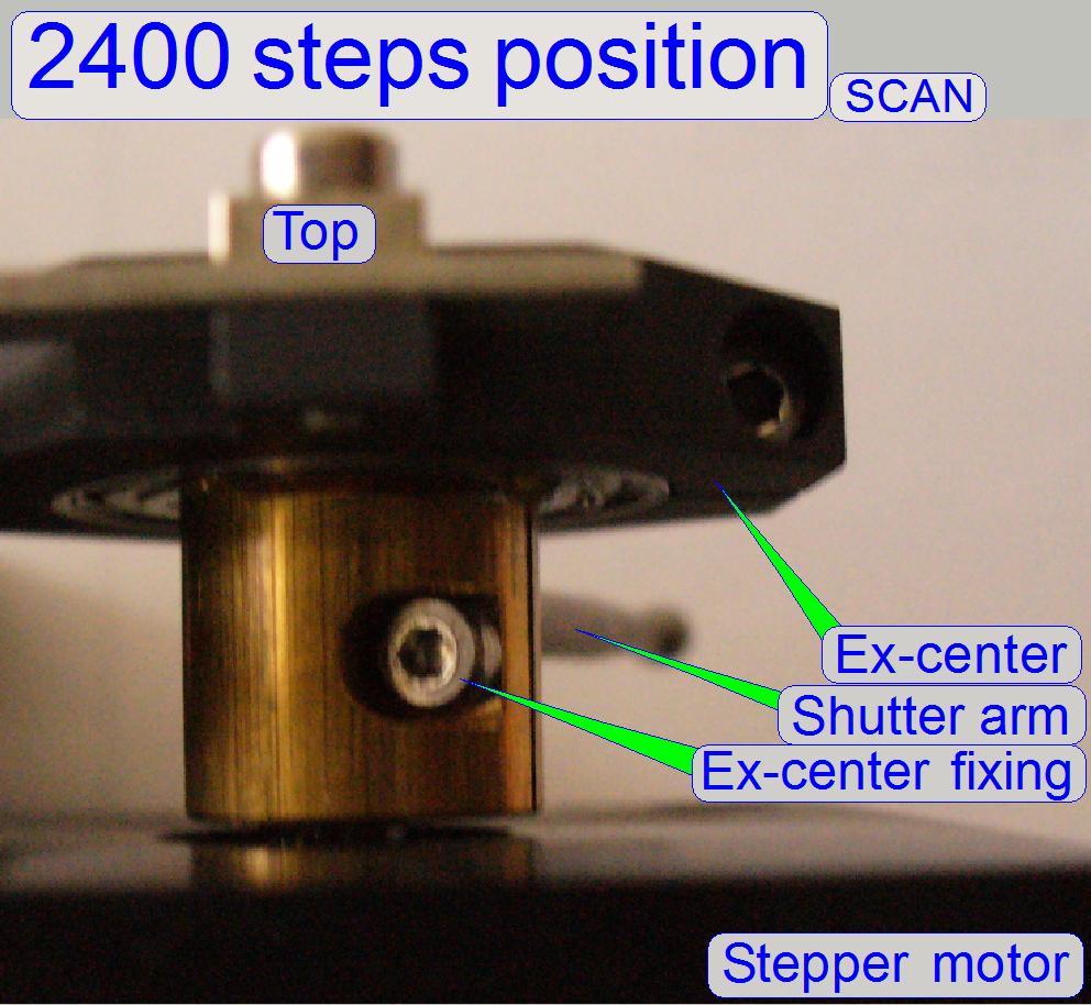
·
Because in this position the fixing bolt can not be
reached, we use the focus position of 2400 steps for this adjustment.
1.
With the service
program set the focus unit to Home1,2.
2.
Go forward to the focus motor position 2400 steps.
3.
 Loosen the ex-center
fixing bolt barely, so that the ex-center can be moved and rotated on the rotor
axle.
Loosen the ex-center
fixing bolt barely, so that the ex-center can be moved and rotated on the rotor
axle.
4.
Set the focus unit to Home1,2.
5.
Go forward to the focus motor position 2400 steps
again.
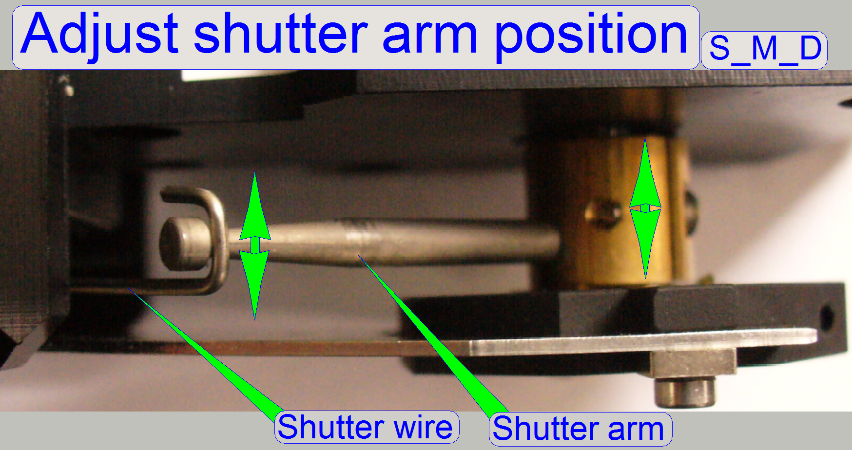
6.
Bring the shutter arm manually into the vertical position
(the shutter arm shows downward and the fixing bolt shows upward). Before you
are tighten the ex-center fixing bolt please check the position of the shutter
arm in relation to the shutter wire also.
·
The shutter arm should touch the shutter wire nearly
in the middle of the hook. To reach this, bring the ex-center in proper
position on the motor axle and tighten the fixing bolt.
7.
 Go to the focus
motor position -300 steps and check the position of the shutter arm in relation
to the shutter wire’s hook. If the shutter arm touches the shutter wire from
beside or the position of the shutter arm in relation to the shutter wire is
unacceptable, repeat from step 1.
Go to the focus
motor position -300 steps and check the position of the shutter arm in relation
to the shutter wire’s hook. If the shutter arm touches the shutter wire from
beside or the position of the shutter arm in relation to the shutter wire is
unacceptable, repeat from step 1.
8.
Go to the positions Home1,2.
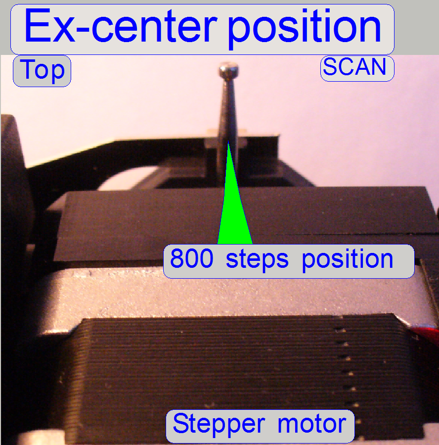
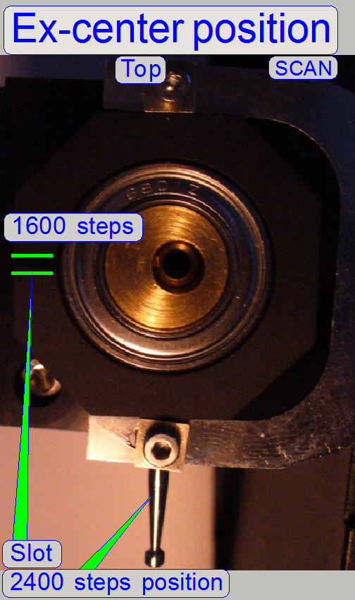
9.
Go forward to the focus motor position +800 steps.
10.
In this position the shutter arm should show exactly
upwards. A deviation of approx. 10 steps from the vertical direction is maximal
allowed. If the deviation is too much, repeat the adjustment from step 1.
·
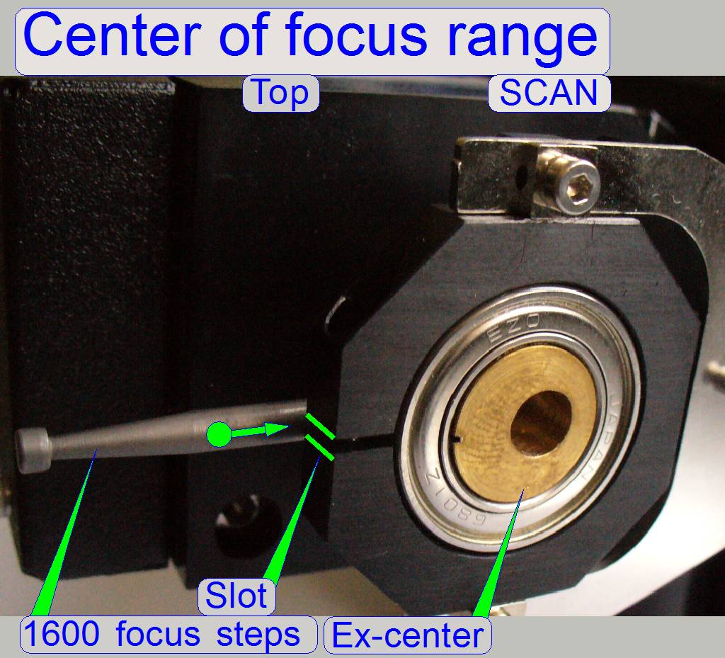 The ex-center
position is correct, if 1600 focus steps are moved and the shutter arm stays in
the middle of the slot. If this condition is not met, please adjust the
ex-center position more precise (maximal tolerance is 10 steps).
The ex-center
position is correct, if 1600 focus steps are moved and the shutter arm stays in
the middle of the slot. If this condition is not met, please adjust the
ex-center position more precise (maximal tolerance is 10 steps).
Find the hardware limits for the focus unit
This procedure must be done
only if the ex-center was dismounted or its fixing bolt was loosened. Before
the following procedure is done, the previous adjustment “Adjust the ex-center
position” should be correct.
![]() “How to define hardware limits”
“How to define hardware limits”
Find the negative limit
11.
 Set the focus unit
to Home1,2.
Set the focus unit
to Home1,2.
12.
Go forward to the focus motor position -300 steps and
check the position of the shutter arm in relation to the shutter wire. If the
shutter wire touches the shutter wire from beside or the position of the
shutter arm in relation to the shutter wire is unacceptable, repeat the
previous step, Adjust
the ex-center position
13.
Go backward +300 steps.
14.
Press Home1 (only). There should be not more then +-2
steps difference to Home1.
If there are more
steps lost, decrease the actual number of steps by 10 and repeat from step
15.
If there are not more then 2 steps difference to Home
1, increase the number of steps by 10 and repeat from step
16.
The negative limit is found correctly if the motor
movement has no steps lost and the actual number of steps, increased by 10
would produce lost steps.
The found negative
limit can differ by more ten steps from unit to unit. The reasons are the
tolerances of the components and the used position of the ex-center in relation
to the motor axle.
17.
The negative limit is found correctly if the motor
movement has no steps lost and the actual number of steps, increased by 10 would
produce lost steps.
The found negative
limit can differ by more ten steps from unit to unit. The reasons are the
tolerances of the components and the used position of the ex-center in relation
to the motor axle.
18.
Update the
parameter value of the parameter “FocusDeviceMin” with the
found number of the actual steps in the file “MicroscopeConfiguration.ini” section [HardwareLimits].
19.
Update the parameter
value of the parameter “CondenserCoverOff” with the found value in the file “MicroscopeConfiguration.ini” section [Focus].
Find the positive limit
20.
Set the focus unit to Home1,2.
21.
Go forward to the focus motor position +3550 steps.
22.
Go backward 3550 steps.
23.
Press Home1 (only). There should be not more then +-2
steps difference to Home1.
If there are more
steps lost, decrease the actual number of steps by 10 and repeat from step
24.
If there are not more then 2 steps difference to
Home1, increase the number of steps by 10 and repeat from step
25.
The positive limit is found correctly if the rotor
movement has no steps lost (max. 2 steps) and the actual number of steps,
increased by 10 would produce lost steps.
The found positive
limit can differ by more ten steps from unit to unit. The reasons are the
tolerances of the components and the used position of the ex-center in relation
to the motor axle.
26.
Update the
parameter value of the parameter “FocusDeviceMax” with the
found value in the file “MicroscopeConfiguration.ini” section [HardwareLimits].
27.
Update the
parameter value of the parameter “CondenserCoverOn” with the
found value in the file “MicroscopeConfiguration.ini” section [Focus].

· To exchange the objective, please see also “Objective mounting”
1.
Disconnect the cable from the focus unit.
3.
Loosen the objective fixing and remove the objective
mounting and holding nut.
4.
Mount the objective. Hold the mounting nut with one hand
and tighten the objective by manually with the other hand.
5.
Drive in the objective holding nut into the focus
unit.
6.
Adjust the distance of the objective to the plane of
the focus pin until a gap of approx. 3-
7.
Mount the focus unit and connect the cable.
 This adjustment assumes that the focus mechanics is
fully is adjusted, except the objective position.
This adjustment assumes that the focus mechanics is
fully is adjusted, except the objective position.
· Important for this adjustment is a slide with a
thickness of 1.0mm (measured with the caliper and without cover slip) and the
focus position of a tissue part must be known; otherwise, the following
adjustment will be incorrect; outside the tolerance!
1.
Start the slide
scanner program, insert a slide with a tissue (the real focus position of the
tissue should be known) and create a live view; the known focus position of the
tissue should be near to 1600 steps, the nominal focus position.
2.
Produce a live
view and set the focus motor position to the known focus position (or 1600
steps).
3.
Loosen the
objective mounting nut barely by loosening the objective fixing bolt.
4.
Drive the
knurled objective nut so, that the objective moves toward the tissue or away
from it until the focus is found.
5.
During
tightening the fixing bolt of the objective, observe the live view and correct
the objective position as necessary.
6.
Check the
adjustment with the option “Auto focus”; a tolerance of 25 focus steps to the
known focus position is allowed.
7.
Repeat from
step 2 if necessary.
8.
Check the focus
position with tissues, different in thickness. The focus position of the
thickest (muscle) and thinnest (blood) tissue should be always inside the focus
range from 1200 to 2000steps!
The adjustment of the
condenser is important for the bright, uniform and optimal illumination of the
FOV. This reduces so the exposure time of the camera and increases the quality
of the scanned tissue. If the objective position was modified, the correctness
of the condenser position has to be checked again!
·
This adjustment assumes that the entire focus unit is
adjusted and the correct objective position is found; this should be always the
last adjustment of the focus unit.
1. Create a live view
with the scan camera in the focus tab and set the focus motor position to 1600 steps.
2. With the preview positioning tool ![]() find a
“clean” FOV outside the tissue and inside the cover slip, without dust.
find a
“clean” FOV outside the tissue and inside the cover slip, without dust.
3.
Loosen the condenser’s fixing bolt.
4.
Rotate the condenser toward to the
objective, to find the start position for the adjustment; the brightness will
increase.
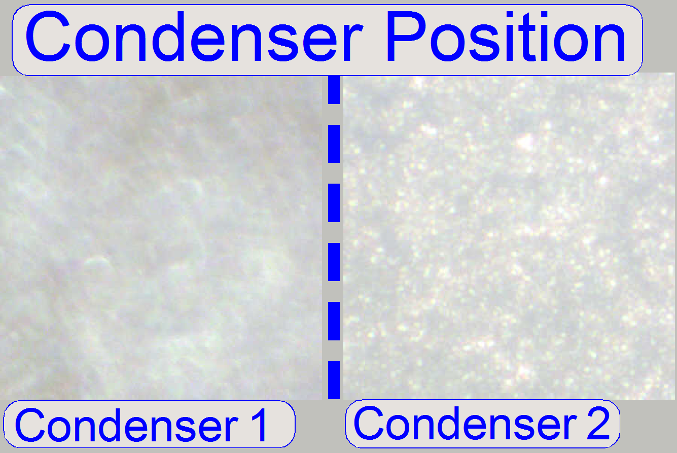
5.
Rotate the condenser in opposite
direction and look at the live view. Beware of the condenser cover (mechanical
shutter), don’t close it and don’t bend it. You will see two surfaces (from the
diffuser) coming into focus (see “Condenser 1 and
6.
After the second surface just disappeared (Condenser
2) and the live image is smooth and bright (“Condenser position”), stop moving
the condenser and tighten its fixing bolt (the image was done with previously
adjusted illumination. If you are starting the adjustment, the figure
“Condenser position” might be is not so smooth).
7.
If the brightness decreased too much, repeat from step
3.
Check the shutter closed position
·  During a fluorescent FOV is visible on the screen as a
live view, switch on and off the bright field illumination several times with
the service program. If the shutter is in proper position the brightness of the
view must not change.
During a fluorescent FOV is visible on the screen as a
live view, switch on and off the bright field illumination several times with
the service program. If the shutter is in proper position the brightness of the
view must not change.
Check the shutter open position
· During LUT-adjustment the FOV is visible on the screen
as a live view. Try to bring the shutter wire manually more into the shutter
off position (the -300 limit) and observe the screen. If the shutter is in
proper position the view of the LUT adjustment must not change.
Remark
In the DESK, the shutter closed
position (fluorescent scan mode) will never be used, but check always the
“Shutter open” position!
· If the illumination path is partially cut by the
incorrect shutter position, an evenly illumination of the FOV will never be reached!
This is true for all scanner types also.
Dismount or mount the focus unit
Focus unit mounting
 In previously
developed SCAN,
In previously
developed SCAN,
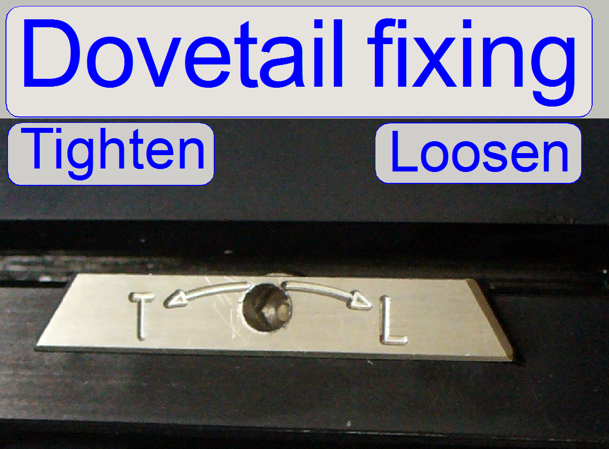
In newer scanner types the
focus unit and the X-Y-stage are fixed with a dovetail solution. In this case,
opposite as usual, drive the mounting bolt clockwise to loosen and counter
clockwise to tighten the fixing.
If the X-Y-Stage is in the
home position, the focus unit can not be removed; therefore step 1 must be
always done before the focus unit will be removed or inserted and the X-Y-stage
is in home position.
![]() “Scanner plate” and “Dovetail fixing”
“Scanner plate” and “Dovetail fixing”
Dismount
the focus unit
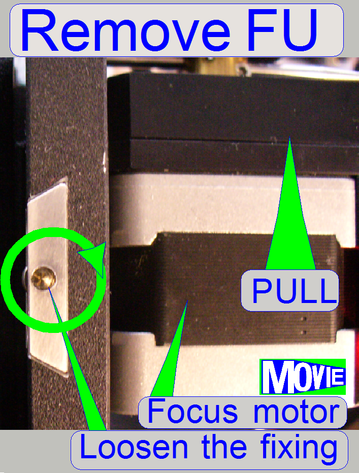
1.
With the service program go forward to the
position 10,000 steps in +X direction (3 revolutions of the motor axle).
2.
Disconnect the cable of the focus unit.
3.
Loosen the fixing bolt of the focus unit mounting.
4.
Remove the entire focus unit by pulling the unit
backward.
Mount
the focus unit
5.
Insert the focus unit into the dovetail until the
physical limit is reached. Take care on the objective!
6.
Tighten the fixing bolt of the focus unit mounting.
7.
Connect the cable.
Watch Video: Remove focus unit (SCAN)