Optics, illumination; S_M_D
For technicians and
partly for sales managers!
This chapter handles the components of
the brightfield illumination and the optical path for Pannoramic scanners;
previously released descriptions about the brightfield illumination are no
longer valid. Because our products are developed continuously, some items in
the shown menus may differ to the actual software version you are using.
To help resolve problems with
illumination and optics, a hardware description of the implemented components
and adjustment procedures are added.
For
safety regulations regarding human health and scanner functionality please
refer to: Precautions
Contents
Adjust uniform illumination with
LUT
Check the optical
path adjustments
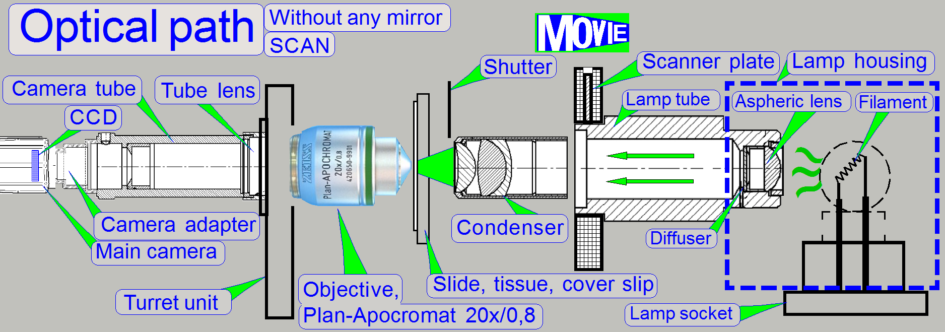

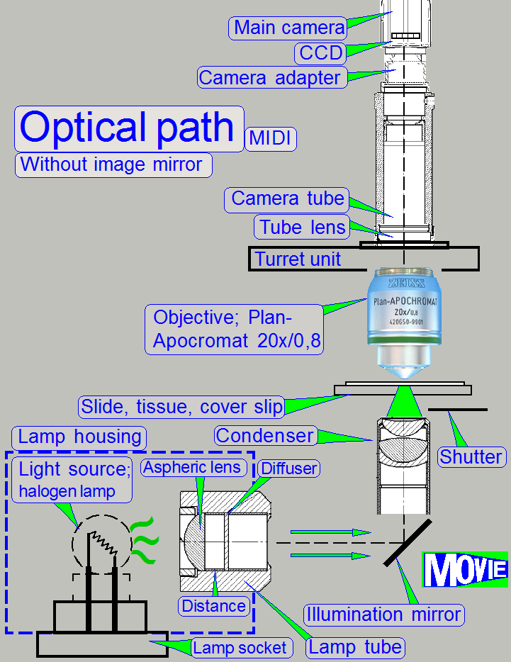
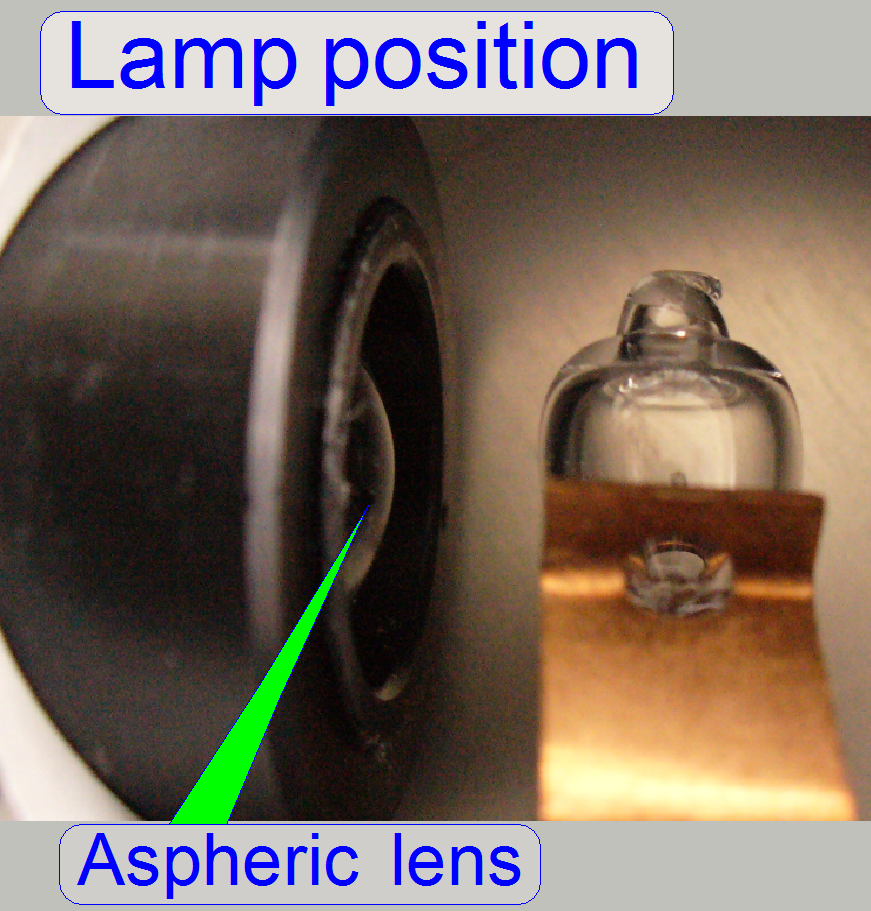
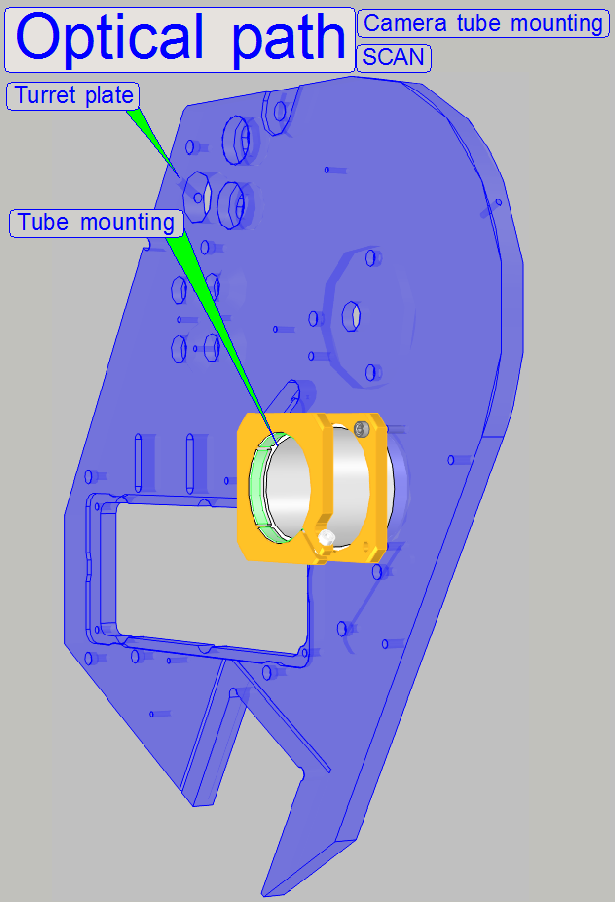
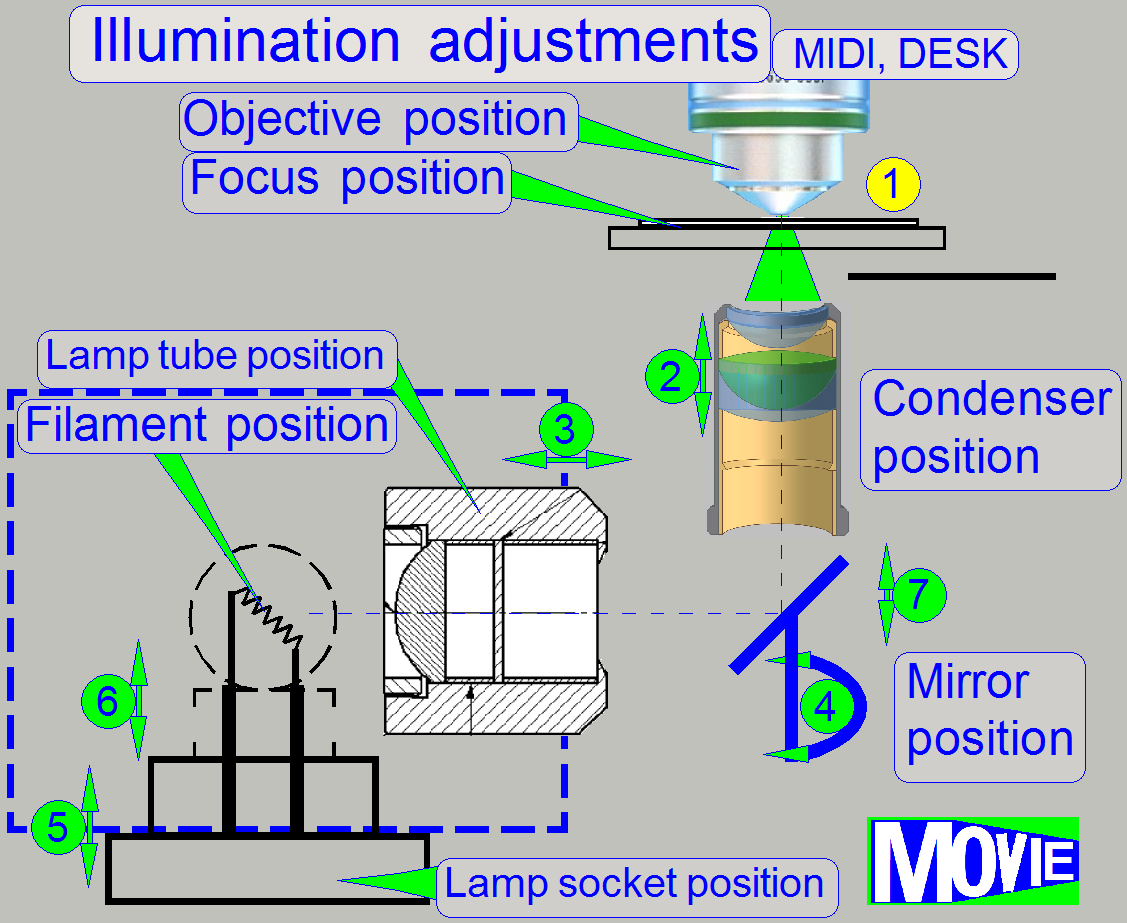
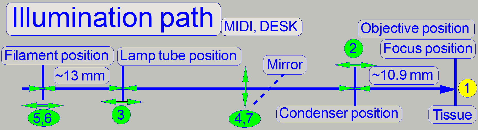
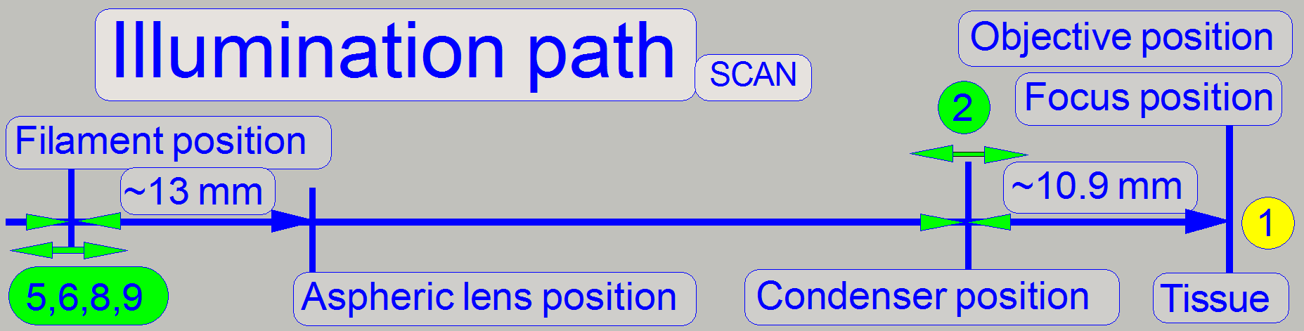
The emitted light of the light
source is collected by the aspheric lens in the illumination tube and the produced
parallel light rays are sent to the illumination mirror (DESK,
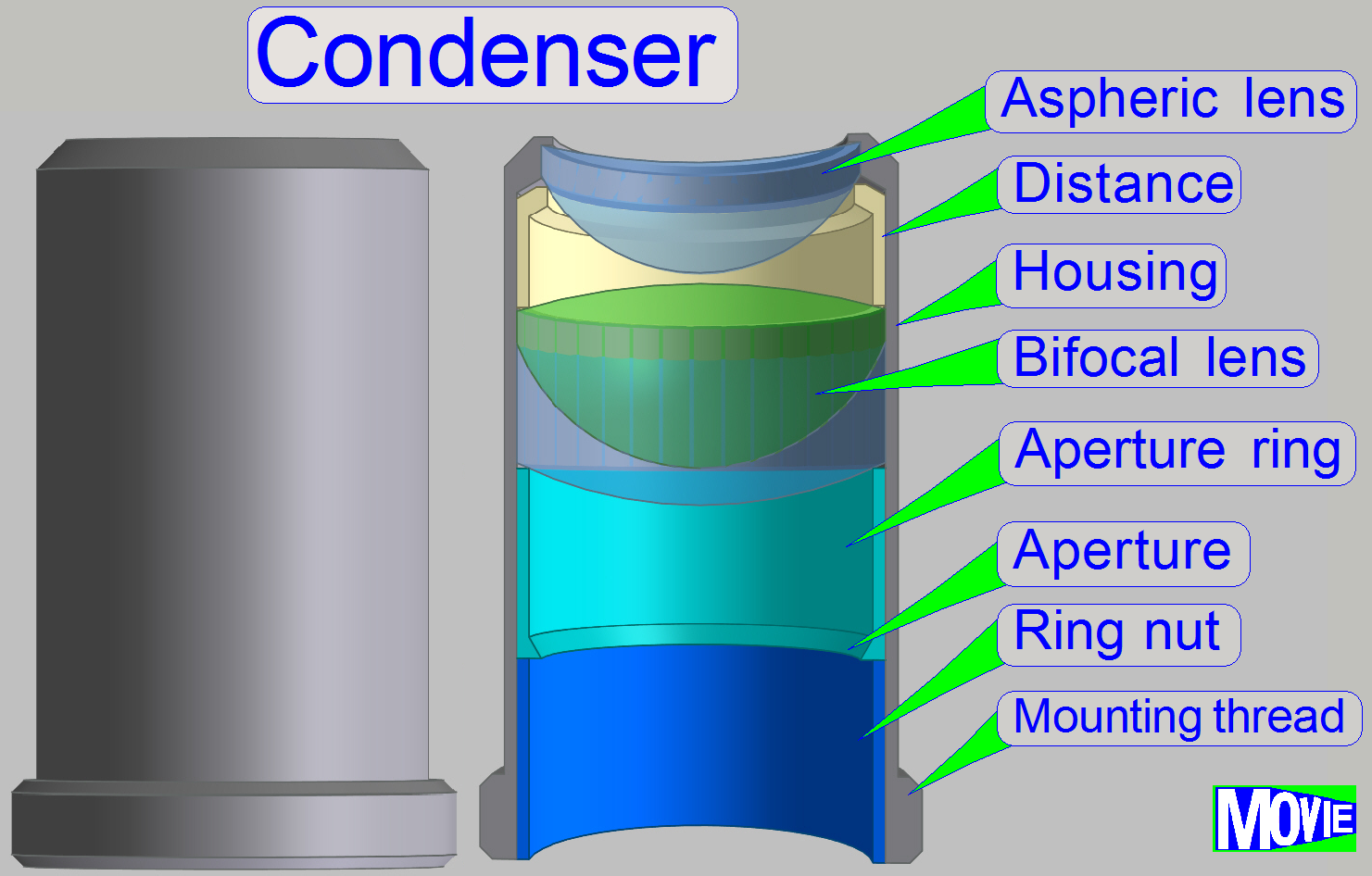
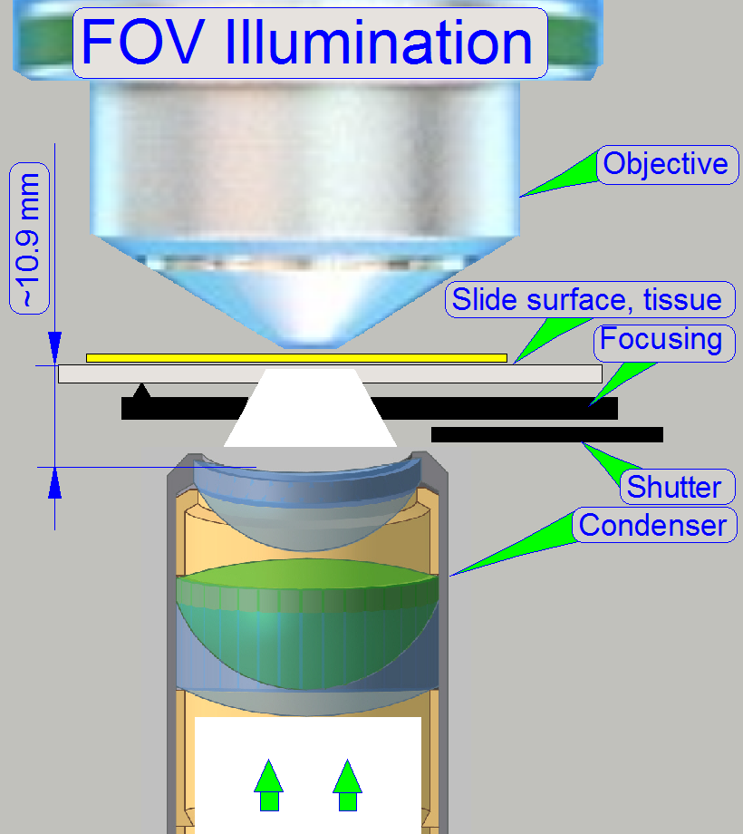
The condenser concentrates the light
to that area of the tissue that is just observed by the objective’s pupil and
the scan camera; the condenser illuminates the field of view (FOV) evenly.
The light, emitted by the tissue is
collected by the objective; the objective performs the image, together with the
tube lens.
Into the space between objective and
tube lens optical components can be inserted, like the fluorescent filter block
(SCAN,
The image, created by the objective
together with the tube lens can be modified in its size by using camera
adapters with different magnifications.
The reached magnification, seen by
the CCD of the main (scan) camera is the result of the product of objective
magnification and camera adapter magnification.
The CCD of the camera transforms the
incoming light into electrical charge, this is read by the camera electronics
and the composed data stream (the image) is transferred to the software.
Example: If the
objective magnification is 20x and a camera adapter with a magnification of
0.63x is implemented, the resulting magnification is 12.6x.
Remark: The
magnification of the camera adapter can not be varied as desired, the
construction of the image path and the size of the CCD of the used camera
limits the usable camera adapter magnification.
![]() “Optical path and
Field Of View”
“Optical path and
Field Of View”
“Influence of the camera
adapter” and “Useable resolutions of scan (main)
cameras”
The used components are nearly
identical in all the three scanner types (S_M_D)); but the mechanical
construction requires some detailed modifications. Differences are named as
they occur in the description.
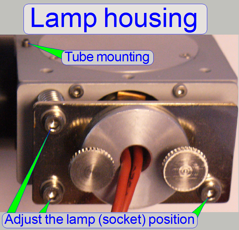
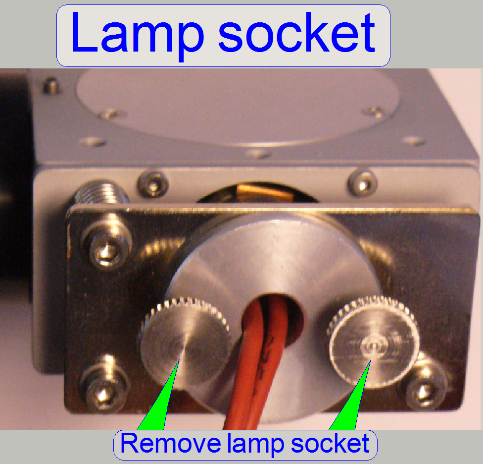
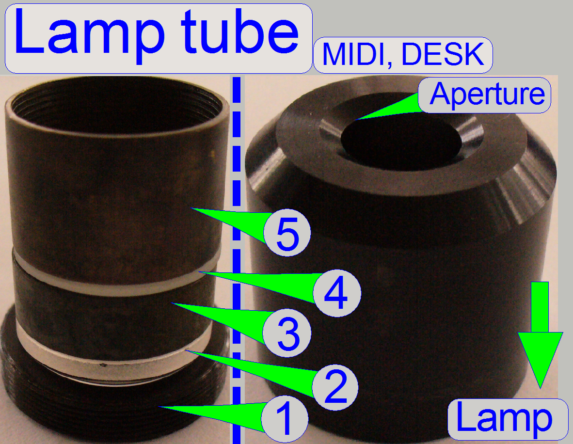
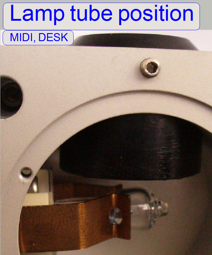
The lamp housing is designed to
reflect light as much as possible to the aspheric lens. Essentially, the
distance of the filament to the aspheric lens is important. For best illumination
results, the filament should be in the focus of the aspheric lens; this
distance is ~13mm. To reach this, the position of the lamp socked (and so the
filament position) can be adjusted.
- To
exchange the lamp, the two knurled bolts should be removed.
![]() “Adjustment procedures”
“Adjustment procedures”
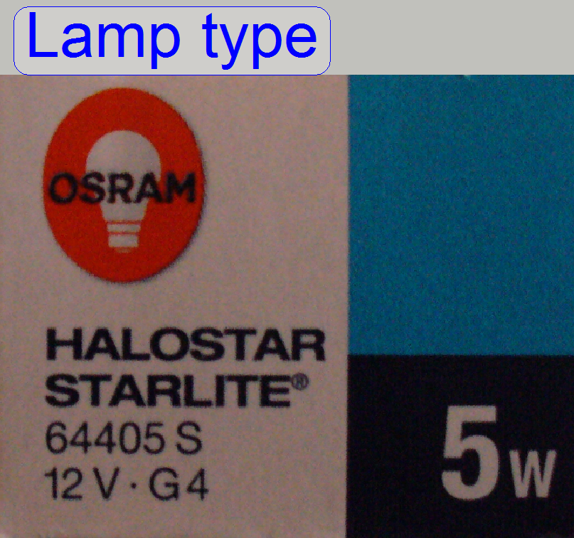
 A halogen
lamp with a power of 5W is used as light source to illuminate the tissue.
A halogen
lamp with a power of 5W is used as light source to illuminate the tissue.
![]() “Adjustment procedures”
“Adjustment procedures”
Attention
Never touch the lamp glass with fingers!
The lamp will burn out in a half of an hour. If you have done so, clean the
lamp glass with alcohol before switching on the lamp.
Important
· Please do not use a lamp with a power less than 5W! If
the power of the halogen lamp is reduced, the delivered amount of light will be
also less and may be not enough to illuminate the FOV; even if the tissue is a
little bit thicker or the 40x objective is used. The software will interrupt
the scan process or will reporting “Illumination error” during start up the
software.
· Please do not use a lamp with a power more than 5W! If
the power of the halogen lamp is increased, the control output of the
brightfield scan illumination may be destroyed!
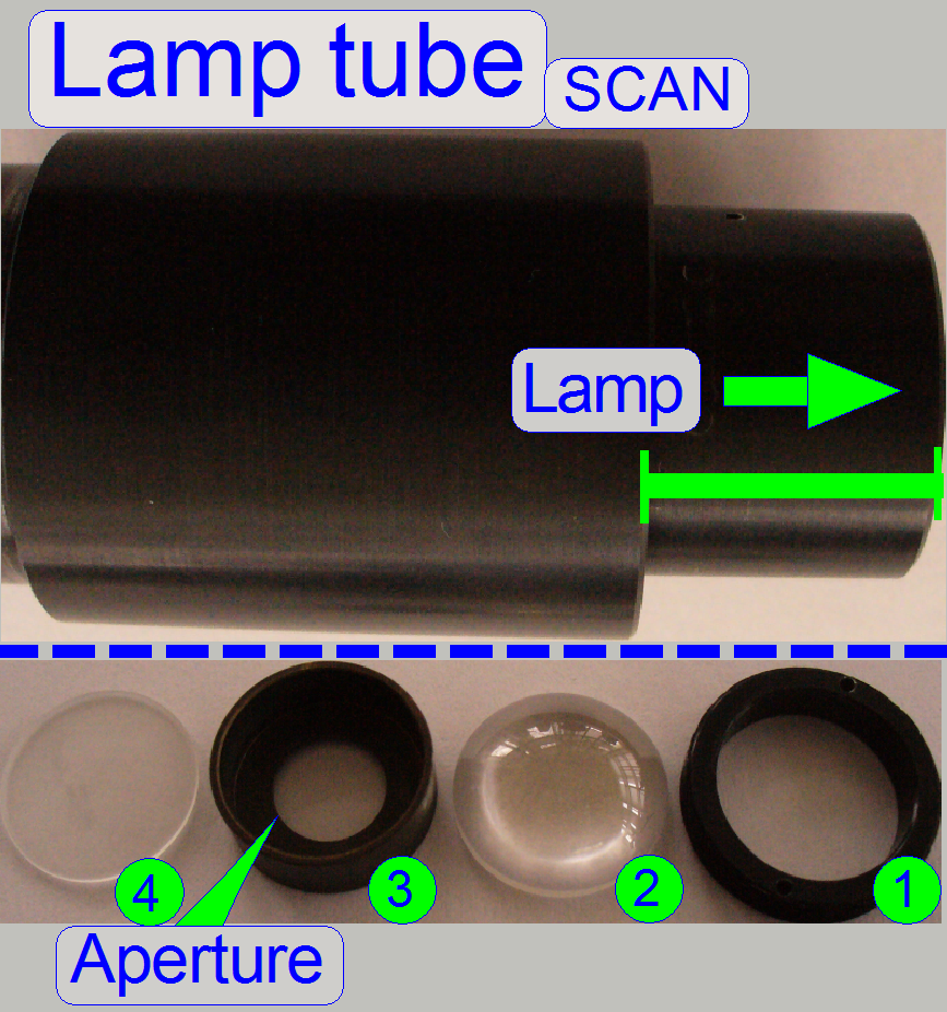
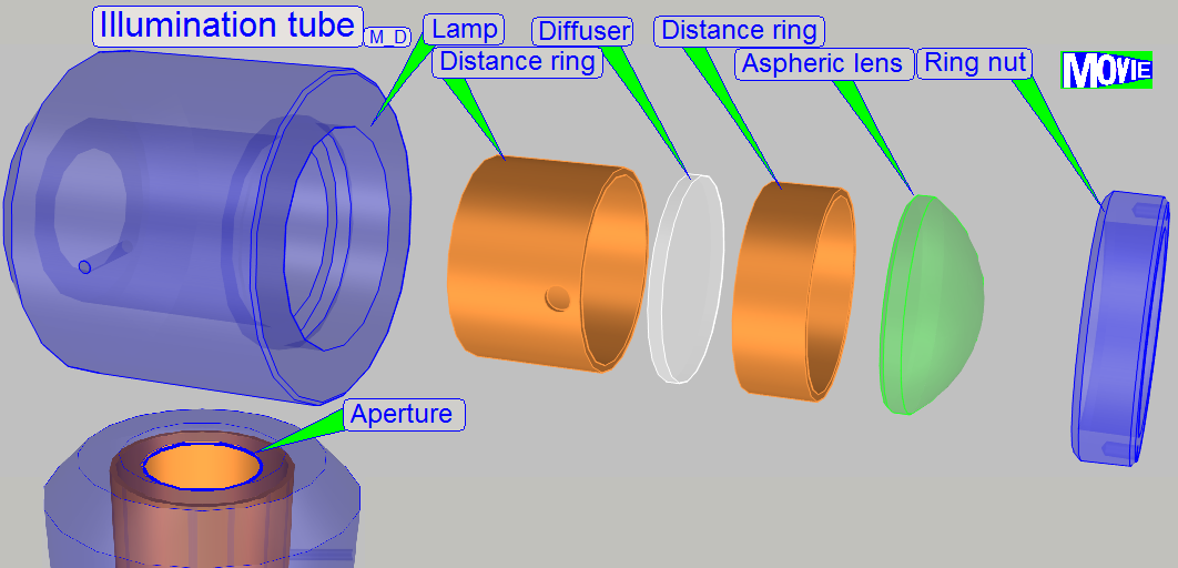
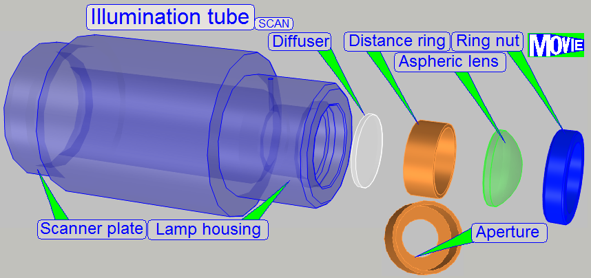 In scanners the illumination
of the tissue is very important. The lamp (illumination) tube contains the
optics to produce light with a high density and coherent rays; so, the field of
view can be illuminated evenly.
In scanners the illumination
of the tissue is very important. The lamp (illumination) tube contains the
optics to produce light with a high density and coherent rays; so, the field of
view can be illuminated evenly.
1.
Ring nut
2.
Aspheric lens.
The focus position is ~13mm.
3.
Distance ring
“a”; SCAN: the aperture is
near to the diffuser
4. Diffuser
5. Distance ring “b”
·
The convex side
of the aspheric lens shows to the lamp.
·
The rough
surface of the diffuser shows to the lamp.
·
The distance ring “a” (3) has no aperture in
·
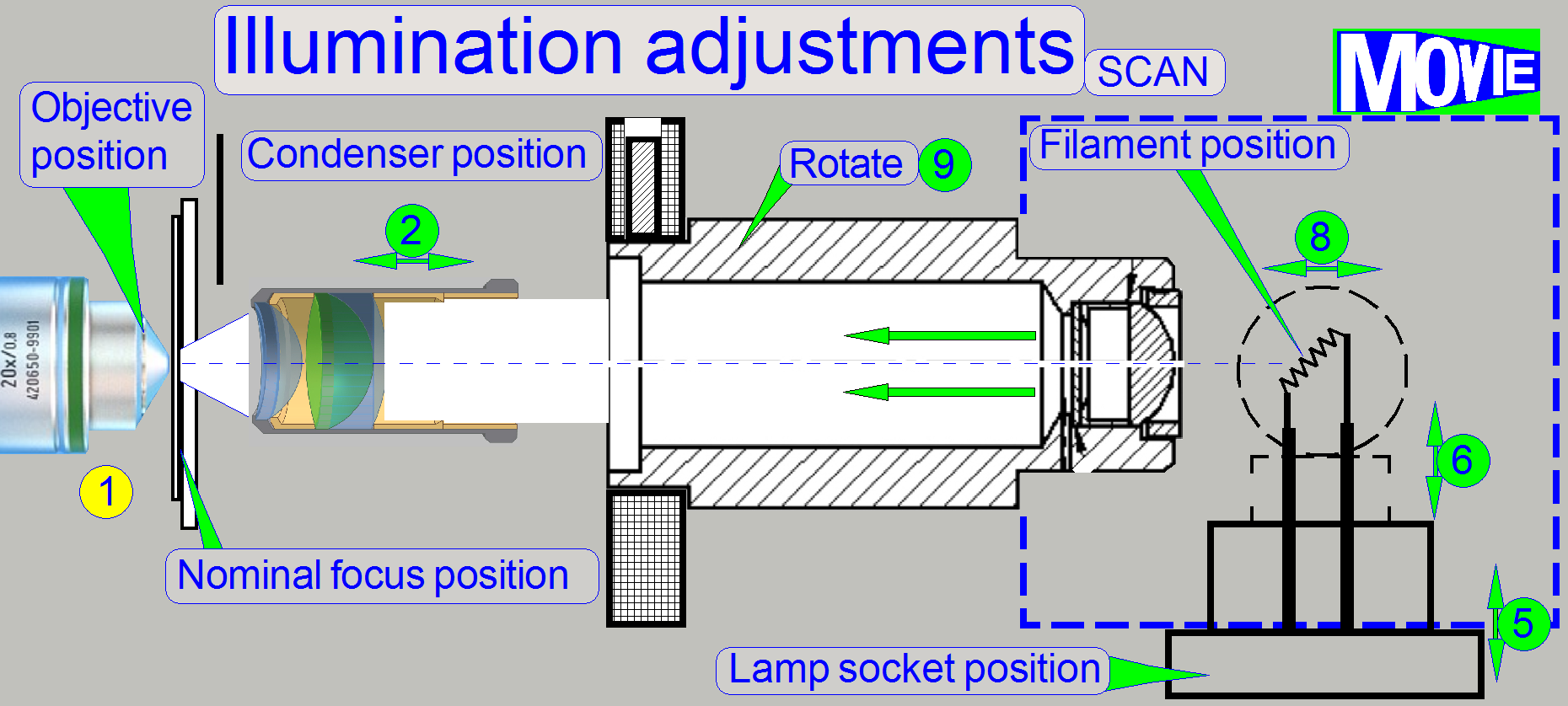
 In the SCAN, the position of the lamp tube is fixed; during in
Illumination mirror;
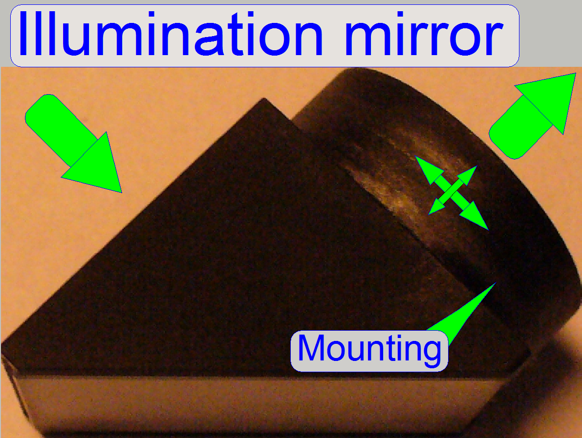
Because in
· For best illumination results the mirror position must
be adjusted; see also “Adjustment procedures”.
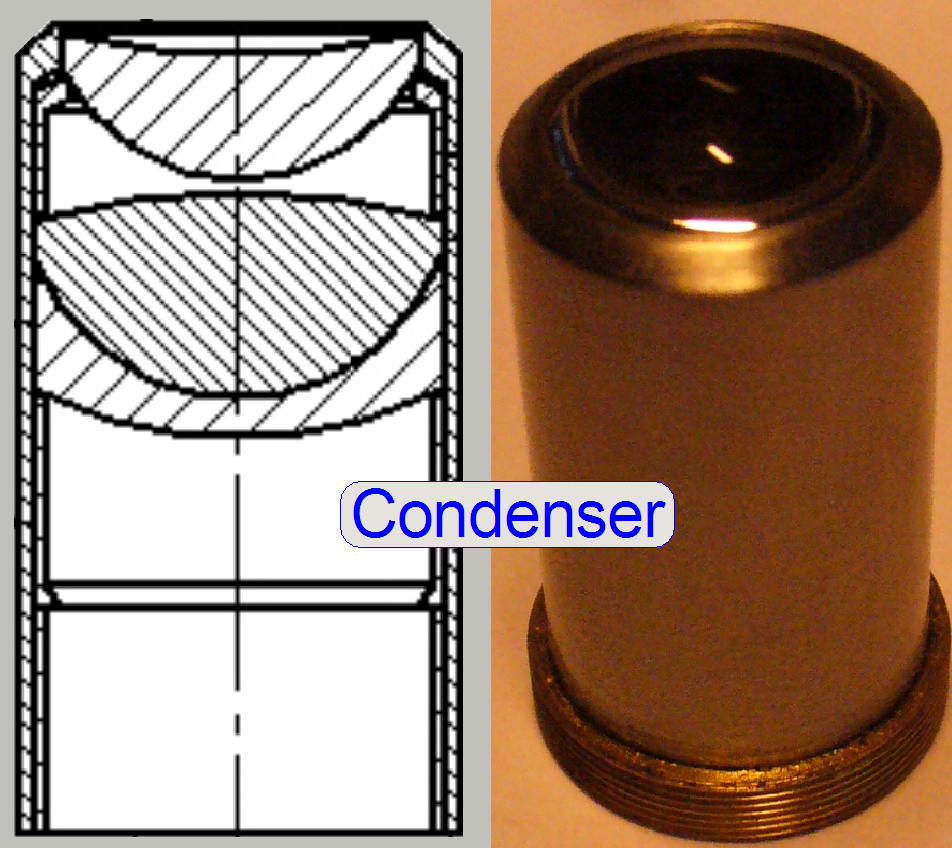
The condenser concentrates
the incoming light to the field of view (FOV).
Because the size of the illuminated part of the tissue is critical, the
condenser position can be adjusted; the focus position is 10.9mm nominal.
Remark
The best illumination results would be reached if we would use an
objective also to illuminate the field of view; but because objectives are very
expensive, a condenser is used.
· In optical aspects
we can say, the condenser is a simplified objective.
![]() “Focus unit”.
“Focus unit”.
Condenser ; Wikipedia
Condenser; © microscopy-uk.org
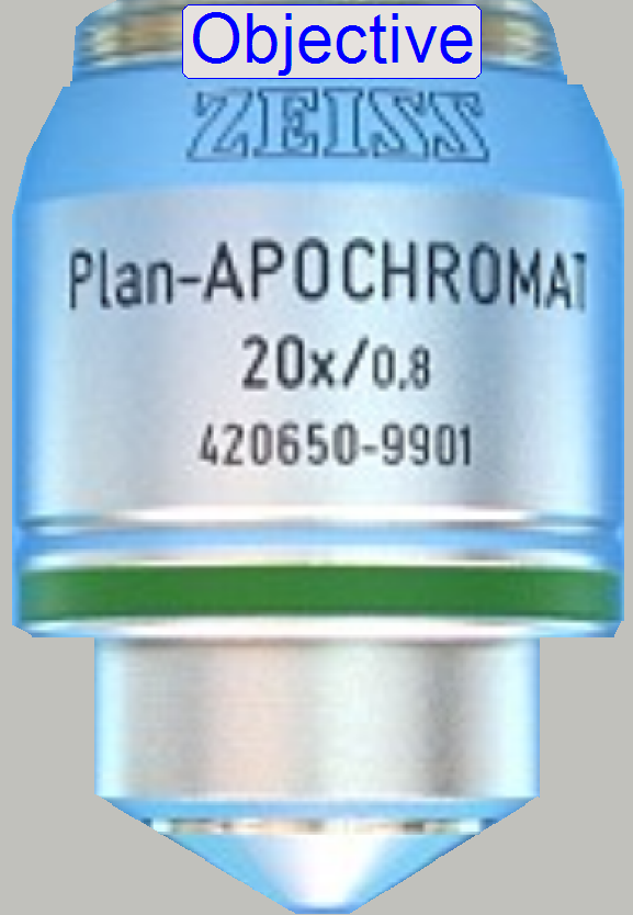 In microscopes, the objective gathers the light, emitted
from the tissue to be observed and focuses the rays to produce an image. The
character of the objective is given by the magnification and the
numerical aperture.
In microscopes, the objective gathers the light, emitted
from the tissue to be observed and focuses the rays to produce an image. The
character of the objective is given by the magnification and the
numerical aperture.
The position of the objective and
the distance to the tissue is very important to produce a sharp image. Because
in Pannoramic scanners this distance can be modified by moving the tissue
position (focusing) both positions are important, the objective position
and the nominal focus
position.
Remark
In the standard version of SCAN,
![]() “the
focus
unit”.
“the
focus
unit”.
To
exchange the objective, please refer to the appropriate chapter “Exchange the
objective” in the chapter “How to exchange
spare parts and units”
![]() “Optical path and Field Of View”
“Optical path and Field Of View”
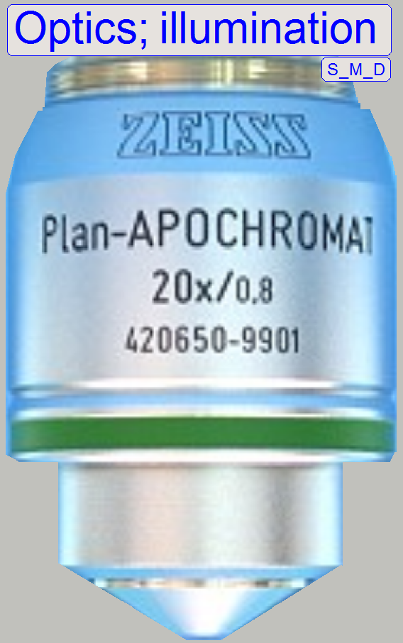
Objective; © Objectives_for_Microscopes_from_Carl_Zeiss;
stored
Slide, tissue and cover slip
Important
If the scan program takes the compensation images after the BF part of SlideScanner.exe
was started and the program stops with the error message
· “The parameter is incorrect”,
please check the
components of the optical path; the camera exposure time is outside the allowed
range!
· The illumination unit
illuminates the tissue; the position of the illumination mirror is correct
· Condenser inserted and
condenser position is correct
· No filter block inserted
in the optical path (10th filter wheel position) and the filter
wheel hardware limits are set correctly
 Since March, 2014; also named as “
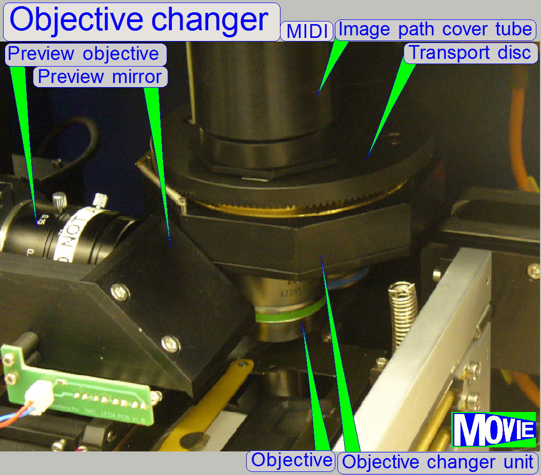
· The focus unit got an objective changer unit, so the
Focus unit OC was created.
The scanner, equipped with the objective changer unit are named as “MIDI
with objective changer” or “MIDI OC” (3Dmic10) and “SCAN with
objective changer” or “SCAN OC” (3Dmic11) and requiring the
software version 1.18 or higher; see also: “What
is new… in the software
version 1.18”
The objective changer unit of the
P250 is mounted onto the focus block of the SCAN and the
The focusing principle and mechanics
are not modified, these parts working as known from the S_M_D; see “Focus unit”.
The objective changer part is the
same as described in the P250; see: “Objective changer”
Cabling: The
turret unit cable is connected to the bus connector of the objective changer
drive unit and the bus cable of the drive unit is connected to the stepper
motor electronics of the turret unit.
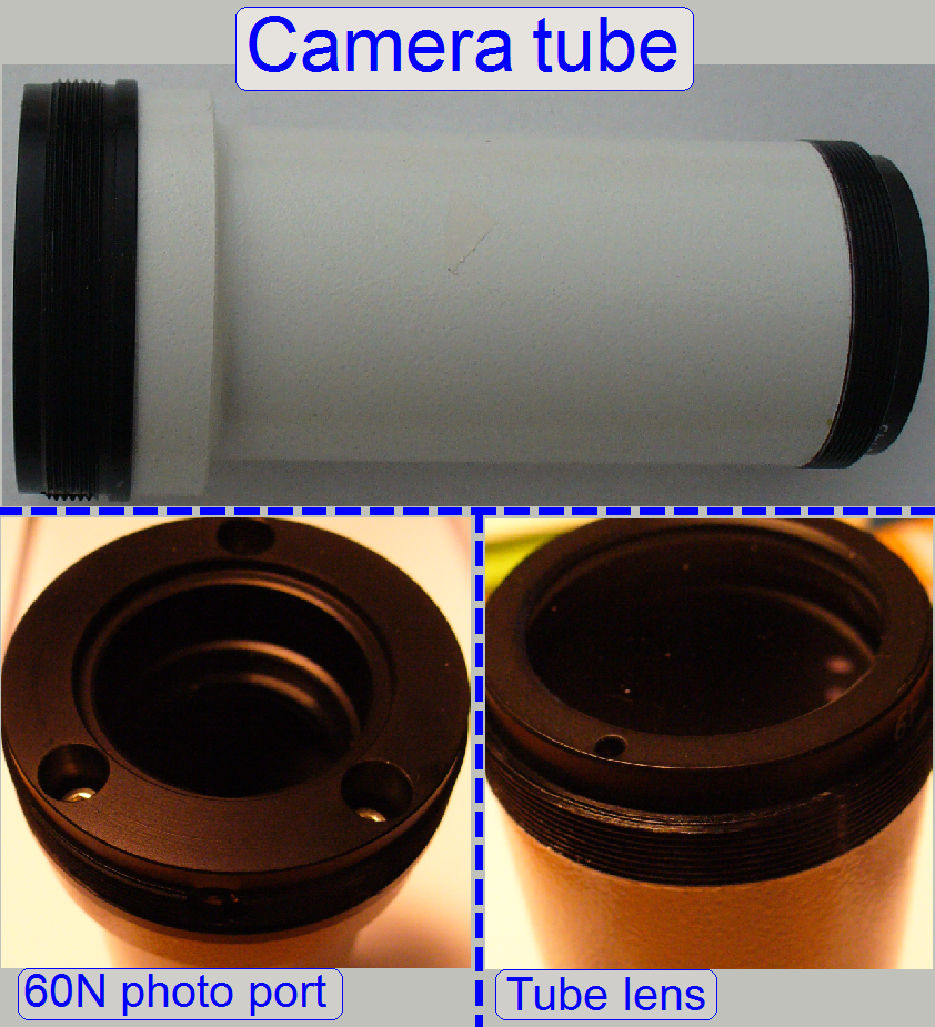
On the side, near to the objective,
the tube lens is situated; this performs the image (together with the
objective). Into the space between objective and tube lens further optical components
can be inserted, like the filter block for the fluorescent scan or a image
mirror like in the DESK. For best image
quality, the tube lens should be mounted into the camera tube until it stops!
- The camera adapter 60 C1” can be also connected
to the 60N interface.
· The camera tube of the DESK is equipped with an
adapter "60 C1” so a 60N interfaced camera adapter can not be connected.
· Since the year 2014, the DESK is also equipped with a
60N photo port.
![]() “Optical path and Field Of View”
“Optical path and Field Of View”
Camera tube mounting; SCAN,
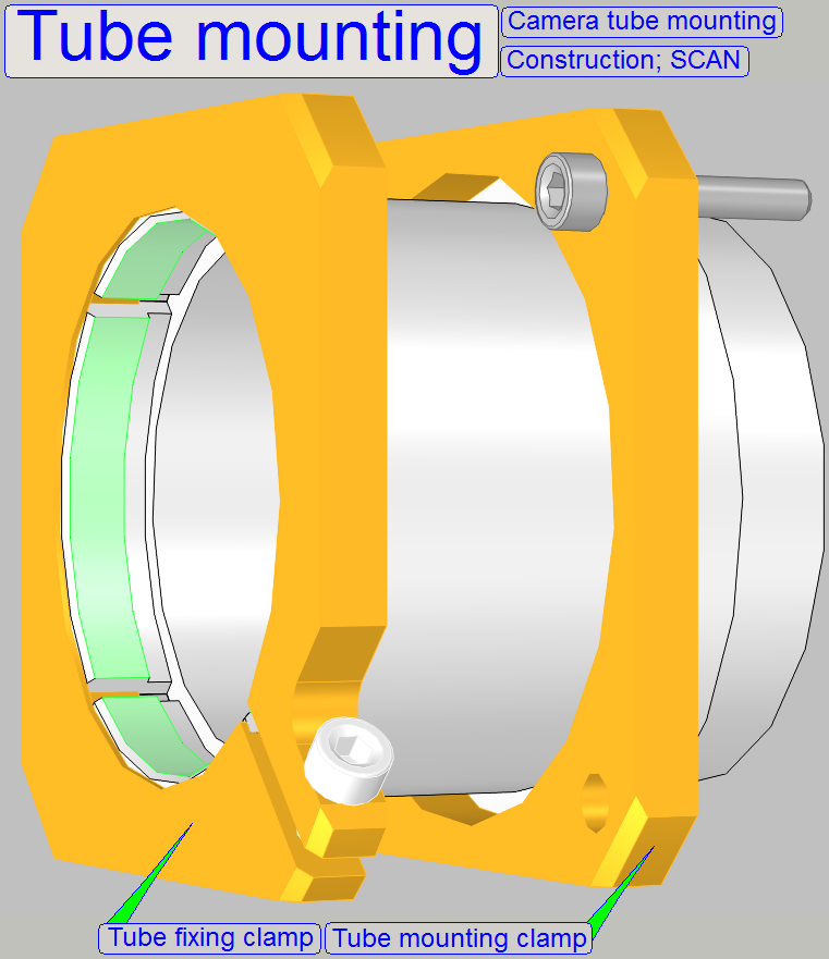 The tube is mounted so, that the correct position can
be adjusted; this way the
chromatic aberration is corrected and minimized.
The tube is mounted so, that the correct position can
be adjusted; this way the
chromatic aberration is corrected and minimized.
·
In
·
For
adjustments, loosen the four clamp mounting bolts to make the tube mounting
barely moveable.
![]() “Adjustment procedures”.
“Adjustment procedures”.
Camera tube mounting; DESK
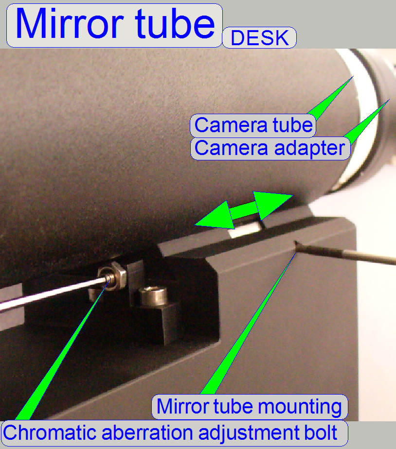 In the DESK,
the camera tube is mounted into the mirror tube; and this is mounted directly
onto the focus unit with a dovetail mounting.
In the DESK,
the camera tube is mounted into the mirror tube; and this is mounted directly
onto the focus unit with a dovetail mounting.
By adjusting the mirror tube
position, the chromatic
aberration is minimized.
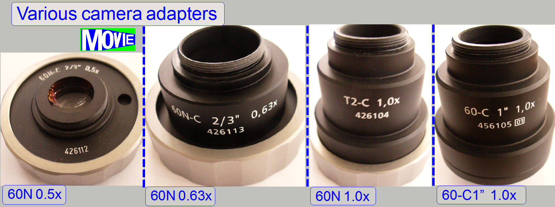 The camera adapter is situated between the camera tube and the scan
camera and offers the possibility to insert lenses or other optical means like
filters into the image path.
The camera adapter is situated between the camera tube and the scan
camera and offers the possibility to insert lenses or other optical means like
filters into the image path.
If lenses are inserted, the camera
adapter modifies the image size and the magnification.
The usable magnification of the
camera adapter depends on the scan camera’s CCD size, its resolution and the
construction of the optical path.

![]() “Influence of the camera
adapter” and “Useable
resolutions of scan (main) cameras”
“Influence of the camera
adapter” and “Useable
resolutions of scan (main) cameras”
Camera adapter ©CARL
ZEISS; Micro shop
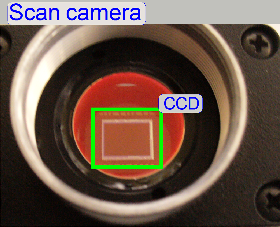 The charge coupled device
(CCD) of the scan camera transforms the incoming light (the image) into electrical
charge; and this is read out by the electronics of the camera.
The charge coupled device
(CCD) of the scan camera transforms the incoming light (the image) into electrical
charge; and this is read out by the electronics of the camera.
Adjust the camera
rotation angle
General
Even illumination is important in
microscopes and in all of our scanners as well. A well adjusted illumination
ensures that any approved camera can be used properly with our scanners without
further adjustments.
The entire adjustment procedure can
be divided into two main parts,
1. The FOV illumination adjustment and
2. The image path adjustment.
The adjustment parts can be done
nearly separately from each other, but always the illumination path is adjusted
first and only then will be adjusted the image path. If the adjustments are
done, the entire result should be checked again!
The adjustment is always done from
the light source to the tissue and from the tissue to the CCD of the camera.
Because distances are not measureable, the actual adjustment result is used to
adjust the next component. This procedure requires adjusting or checking the
position of previously adjusted components again!
 The goal of the brightfield
illumination adjustment is, to illuminate the FOV, seen by the objective
pupil (and the scan camera) evenly and with a density of light as much as
possible.
The goal of the brightfield
illumination adjustment is, to illuminate the FOV, seen by the objective
pupil (and the scan camera) evenly and with a density of light as much as
possible.
· If the FOV is not fully and evenly illuminated, the
quality of the virtual tissue becomes poor (“Stripping”
or “Color shading” occurs), and
· If the illuminated field is too large, the exposure
time of the camera will increase and the scan procedure slows down, because the
light density is reduced.
Because the image, delivered by the
scan camera is used for the adjustments of the illumination path, some
adjustments (Objective- and focus position) for the image path have to be done
before the illumination can be adjusted.
Furthermore, because we using colors
to adjust the illumination path, the final correctness of the illumination path
must be checked with the LUT-adjustment again, after the chromatic aberration
and the camera
rotation angle is adjusted.
 Because the physical solutions in MIDI and DESK are modified in relation
to the SCAN (in the SCAN the illumination mirror does not exist and the lamp
tube position is not adjustable) the adjustment sequence is shown for the
Because the physical solutions in MIDI and DESK are modified in relation
to the SCAN (in the SCAN the illumination mirror does not exist and the lamp
tube position is not adjustable) the adjustment sequence is shown for the
![]() Adjust the objective position and the focus position;
then hold the distance between objective and tissue constant during the entire
adjustment procedure by using always the found number of focus steps!
Adjust the objective position and the focus position;
then hold the distance between objective and tissue constant during the entire
adjustment procedure by using always the found number of focus steps! ![]()
![]()
![]()
Adjust
the condenser position
![]()
Find the
correct lamp tube position
![]()
Find the
correct mirror position
![]()
Adjust
the lamp socket (filament) position.
Do the adjustment of previously
named components again as required; steps 2 - 5.
Adjustment possibilities 6-9
 should be used only, if the adjustments 2-5 does not deliver the desired
results; with this manipulations, the tolerances of the lamp can be affected or
eliminated.
should be used only, if the adjustments 2-5 does not deliver the desired
results; with this manipulations, the tolerances of the lamp can be affected or
eliminated.
- Some
times it helps to exchange the lamp instead!
![]()
Adjust
the lamp position in relation to the socket (pull the lamp out of about 1mm),
![]()
Adjust the
mirror position in relation to the scanner plate (pull the mirror out of about
1mm) and
![]()
Bend the
lamp toward the lamp tube (Scan only, because the tube distance can not be
adjusted).
![]()
Loosen the mounting bolt for the Lamp
tube (if SCAN: loosen the mounting bolt for the lamp housing also) and rotate
the lamp tube. Some times there can be reached more proper results in the SCAN.
 Adjust the objective and focus position
This Adjustment assumes that the
focus unit is adjusted, except the objective position.
·  For further information and adjustments see “Focus unit”.
1.
Start the slide
scanner program, insert a slide with a tissue and create a live view; the known
focus position of the tissue should be nearly to 1600 steps, the nominal focus
position.
2.
Produce a live
view and set the focus motor position to 1600 steps (or the known focus
position).
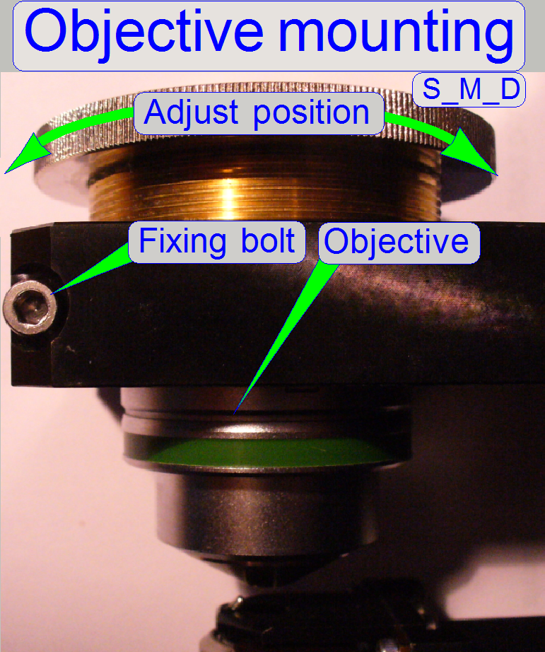
3.
Loosen the
objective mounting by loosening the objective fixing bolt.
4.
Drive the knurled
objective nut so, that the objective moves toward the tissue or away from it
until the focus is found.
5.
During
tightening the fixing bolt of the objective observe the live view and correct
the objective position as necessary.
6.
With the option
autofocus check the adjustment.
7.
Repeat from
step 2 if necessary.
![]() “Mount the objective” and “Adjust the objective
and focus position”
“Mount the objective” and “Adjust the objective
and focus position”

 The adjustment of
the condenser is important for the bright, uniform and optimal illumination of the
FOV. This reduces so the exposure time of the camera and increases the quality
of the scanned tissue. If the objective position was modified, the correctness
of the condenser position has to be checked again!
The adjustment of
the condenser is important for the bright, uniform and optimal illumination of the
FOV. This reduces so the exposure time of the camera and increases the quality
of the scanned tissue. If the objective position was modified, the correctness
of the condenser position has to be checked again!
The position of the condenser affects the following:
· The size of the
visible FOV (color shading)
· The image contrast
·
The
image resolution (the numerical aperture) and
· The exposure time.
1. Create a live view
with the scan camera in the focus tab and set the focus motor position to 1600 steps.
2. With the preview positioning tool ![]() find a
“clean” FOV outside the tissue and inside the cover slip, without dust.
find a
“clean” FOV outside the tissue and inside the cover slip, without dust.
3.
Loosen the condenser’s fixing bolt.
4.
Rotate the condenser toward to the
objective, to find the start position for the adjustment; the brightness will
increase.
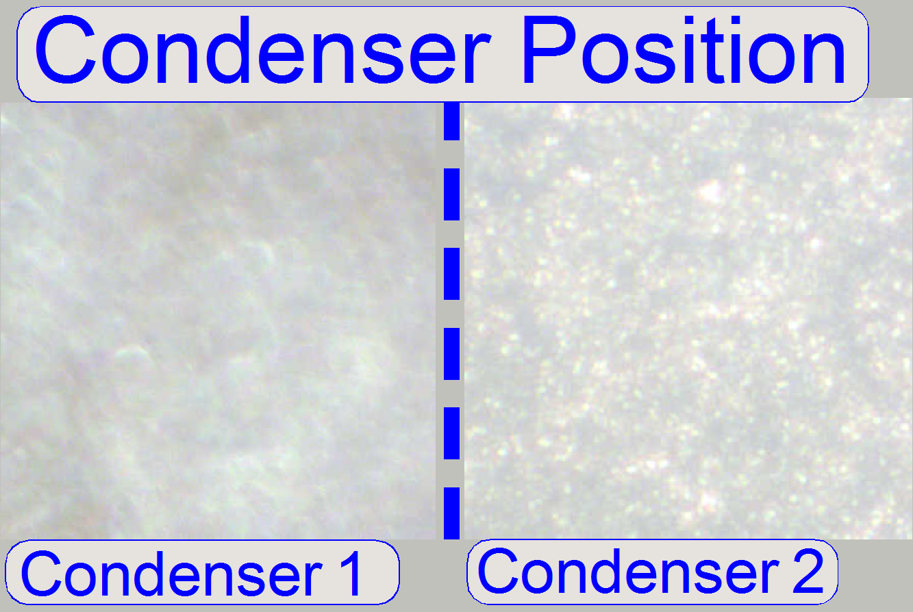
5.
Rotate the condenser in opposite
direction (away from the objective) and look at the live view. Beware of the
condenser cover (shutter), don’t close it and don’t bend it. You will see two
surfaces (from the diffuser) coming into focus (see “Condenser 1 and
6.
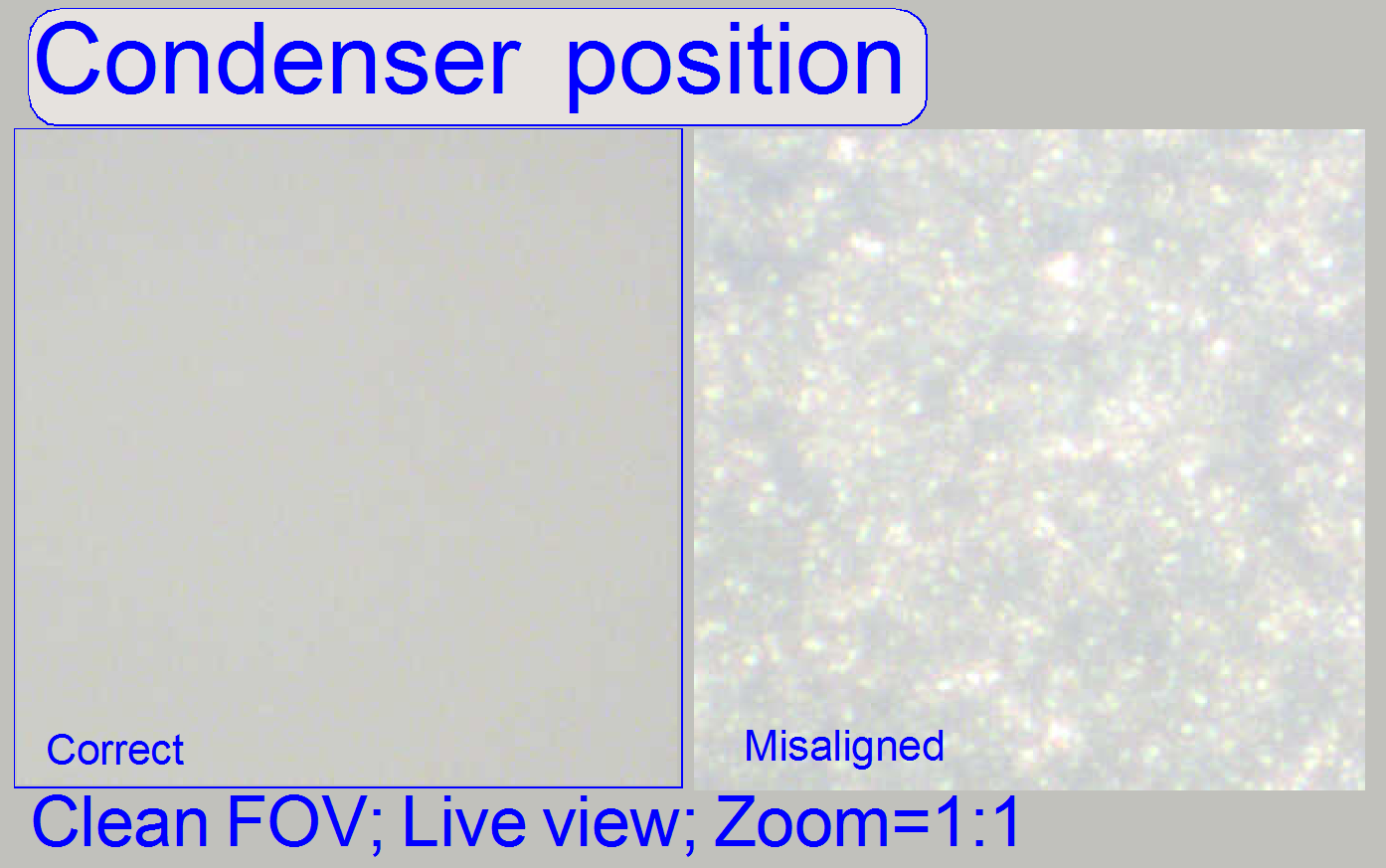
 After the second
surface just disappeared (Condenser 2) and the live image is smooth and bright,
stop moving the condenser and tighten its fixing bolt, see “Condenser position”
(the pictures was done with previously adjusted illumination. If you are
starting the adjustment, the figure “Condenser position” might be is not so
smooth).
After the second
surface just disappeared (Condenser 2) and the live image is smooth and bright,
stop moving the condenser and tighten its fixing bolt, see “Condenser position”
(the pictures was done with previously adjusted illumination. If you are
starting the adjustment, the figure “Condenser position” might be is not so
smooth).
7.
If the brightness decreased too much, repeat the steps
10 to 13.
8.
Check the
correct condenser position in the focus positions 1200, 1600 and 2000 steps.
There must not be significant differences.

Loosen the fixing of the lamp tube (
Tighten the lamp tube fixing bolt.
 If DESK: To
reach the lamp housing and the lamp tube fixing bolt, the scanner plate must be
dismounted from the base plate.
If DESK: To
reach the lamp housing and the lamp tube fixing bolt, the scanner plate must be
dismounted from the base plate.
2.
Disconnect the
preview illumination cable and remove the three mounting bolts of the scanner plate;
then the scanner plate can be rotated by 90 degrees to the left.
 Adjust the illumination mirror position
1.
Illumination
mirror mounting bolt
2.
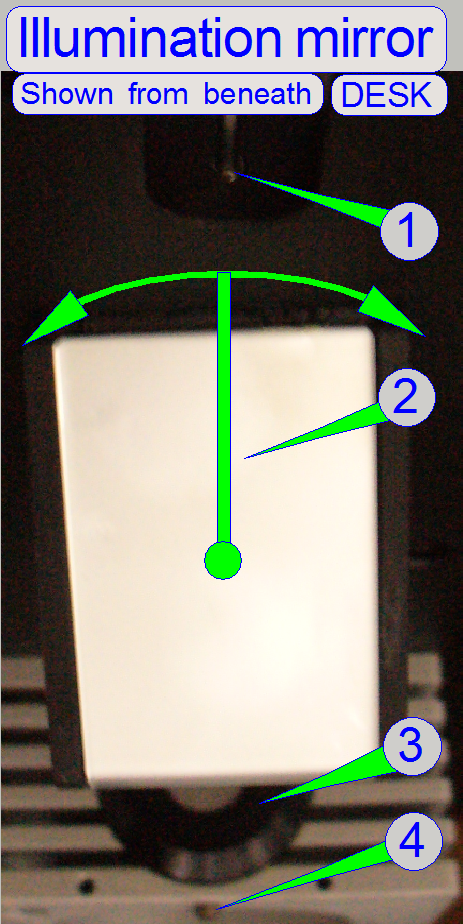 Illumination mirror
3.
Illumination
tube
4.
Illumination
tube mounting bolt
· By rotating the mirror to the left or to the right
respectively and by observing the live view on the screen, the right mirror
position can be found.
· The mirror position should be checked and/or adjusted
more times during the adjustment sequence.
 Adjust the lamp socket (filament) position
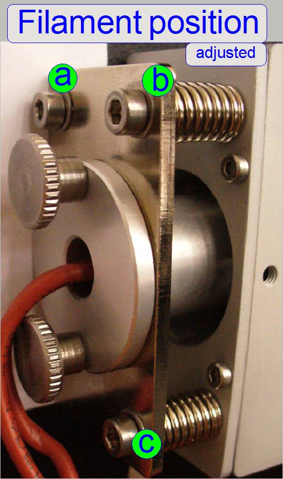 Drive the adjustment bolts “a”, “b” and “c” in or out,
until the optimal position of the filament in relation to the aspheric lens is
found.
Drive the adjustment bolts “a”, “b” and “c” in or out,
until the optimal position of the filament in relation to the aspheric lens is
found.
·
Remove the knurled
bolts of the lamp socket mounting and modify the lamp position in relation to
the socket if required or to exchange the lamp.
Adjust the uniformity of the illumination
with the look up table
General
Even illumination is important in
microscopes and in all of our scanners as well. A well adjusted illumination
ensures that any approved camera can be used properly with our scanners without
further adjustments.
To adjust the uniformity of the
bright field illumination we recommend using the Marlin F-
The Marlin F-146C: The
hardware control for unequally illuminated FOV can be switched off for this
camera and our software use this possibility.
The Stingray F-146C: This
camera can be used also, because the camera driver is the same.
Other cameras: Like
· In the following, the term “Look Up Table” will be used as “LUT”
Requirements
· Scan software with valid
dongle or license file
· Service program with valid license file
· LightCalibration_marlin.csv control file for the marlin
camera, Path: …
website\Descriptions\Files_\LUT-calibration\
·  LightCalibration_stingray.csv control file for the Stingray
camera, Path: …
website\Descriptions\Files_\ LUT-calibration\
LightCalibration_stingray.csv control file for the Stingray
camera, Path: …
website\Descriptions\Files_\ LUT-calibration\
· The installed Marlin F-146C or Stingray F-146C camera
· AVT Smart View
1.6.1. or higher the actual driver
for the Marlin and Stingray camera
· Hex key wrenches M1.5, 2.5, 3, 5
Attention: Do not mix the versions of SlideScanner.exe and
SlideScannerService.exe! Always use these programs with the same version
number. Otherwise the SlideScannerService.exe program could produce unwanted
results and SlideScanner.exe does not work correctly or it may freeze!
![]() Load
the required "LightCalibration"
file for the used camera
Load
the required "LightCalibration"
file for the used camera
Preparations before the LUT adjustment starts
1.
Start SlideScanner.exe; insert a slide with cover
slip.
2.
After the preview is done, select the option Focus and
click the button “Live view”, select the positioning tool![]() ,
click inside the preview window, inside the cover slip and find a well usable
FOV without tissue or dust. The focus position should be 1600 steps.
,
click inside the preview window, inside the cover slip and find a well usable
FOV without tissue or dust. The focus position should be 1600 steps.
3.
Kill the program SlideScanner.exe with the task manager.
4.
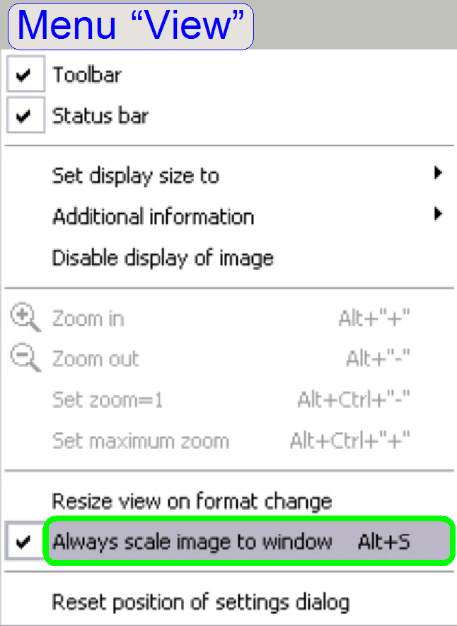
Start the AVT Smart View 1.6.1 or higher and select
the option “Always scale image to window” in the “VIEW” menu.
5.
Start the “Settings dialog” in the menu ”CAMERA” and
“Settings”.
6.
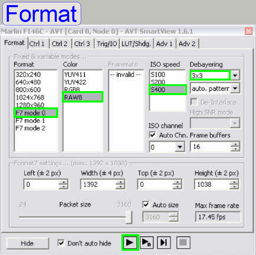 In the window “Format” check the options “F7 mode
7.
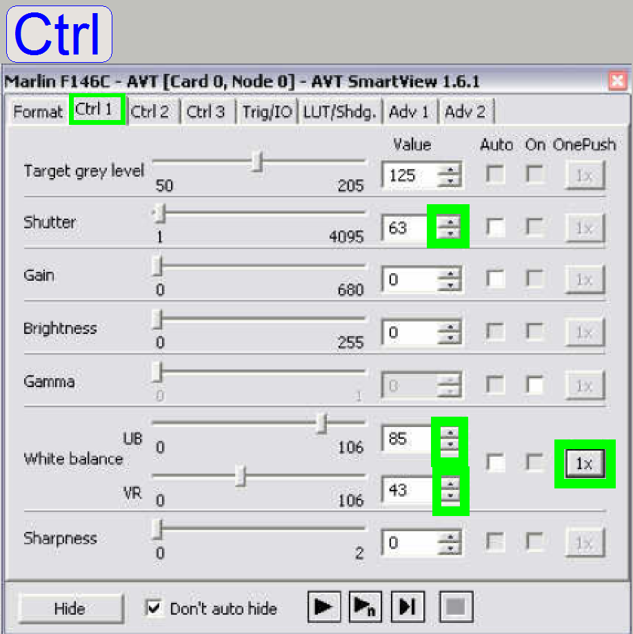 Select the tab
“Ctrl
Select the tab
“Ctrl
8.
Select a “Shutter” value in the range between about 50
to 100 and push the buttons play ![]() and then
and then ![]() at the white balance.
at the white balance.
9.
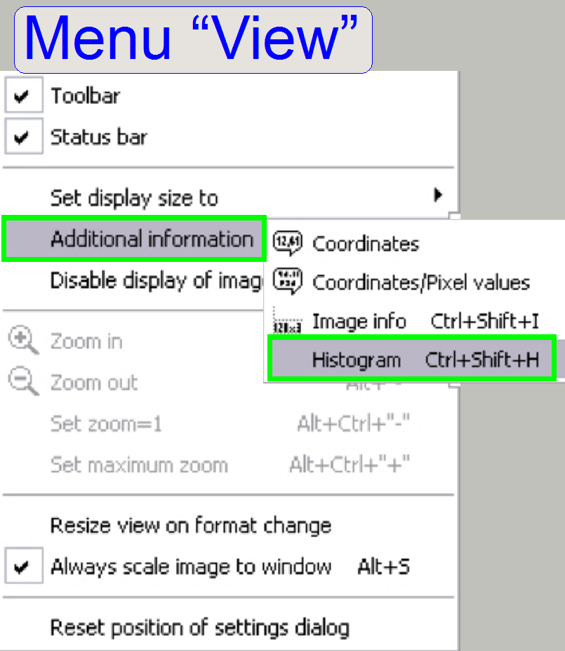 In the menu “VIEW”
and “additional information” select the option “Histogram” (see the menu
“View”).
In the menu “VIEW”
and “additional information” select the option “Histogram” (see the menu
“View”).
10.
Increase or decrease the shutter value until a medium
brightness live view is visible (see Ctrl1).
11.
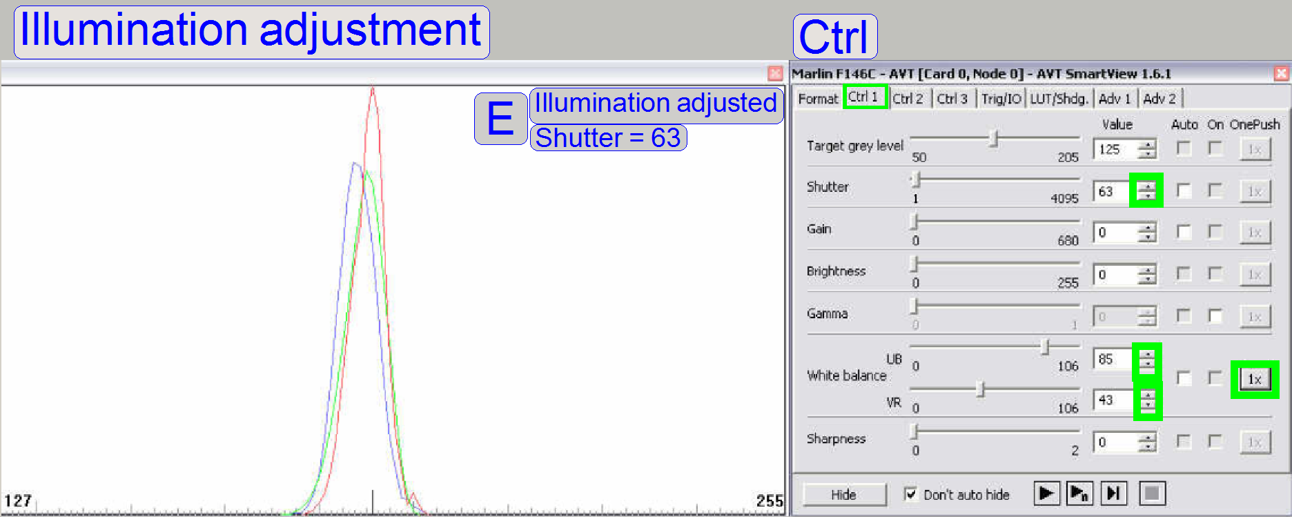 The goal is now to bring the functions of red,
green and blue nearly into cover in the middle of the range between 127 and 255
(modify the shutter value for the red function and the white balance UB and VR
values for green and blue) (E). Possible peaks in the functions can be
eliminated (minimized) later, with the LUT-adjustment.
The goal is now to bring the functions of red,
green and blue nearly into cover in the middle of the range between 127 and 255
(modify the shutter value for the red function and the white balance UB and VR
values for green and blue) (E). Possible peaks in the functions can be
eliminated (minimized) later, with the LUT-adjustment.
To reach the desired results, please adjust the following parts:
1.
 As you can see, the only fix distances are given by
the position of the objective in relation to the position of the tissue (the
focus position) and the condenser position. Therefore, these distances are
defined first.
As you can see, the only fix distances are given by
the position of the objective in relation to the position of the tissue (the
focus position) and the condenser position. Therefore, these distances are
defined first.
· See also above “Adjust the
objective and focus position” and “Adjust the
condenser position”.
2.
The next fixed
distance is the distance of the illumination tube (aspheric lens) to the lamp
(filament), therefore the lamp tube position should be found next (
3.
The mirror
position is important to reflect the entire emitted light to the condenser; if
the position is wrong it affects both parameters, the evenly illumination and
the light intensity.
4.
Because the
filament position is critical, the distance and the position can be fine
adjusted with the lamp socket position adjustment.
 Because there are several adjustment possibilities,
the adjustment steps should be done more times until the best result is found.
Because there are several adjustment possibilities,
the adjustment steps should be done more times until the best result is found.
Adjustment
An essential tool for the bright
field illumination adjustment is the “Look Up Table” (LUT); it is implemented in
the AVT Marlin camera driver. With this tool small deviations from the actual
or optimal adjustment (even if we adjust the mechanics) becomes visible as
color alteration on the screen. Expected results
can be found on the end of this chapter.
Driver settings
for the LUT adjustment
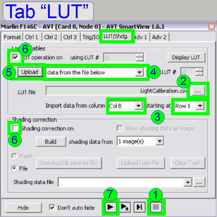
1.
Click on the
tab LUT and stop the live view by pressing the Stop ![]() button.
button.
2.
Select the LUT
file by click on ![]() and select the file “LightCalibration.csv” (for
the camera “Marlin” or “Stingray” as required) from its source folder, we suggest to
use the folder 3DHISTECH\ Pannoramic SCAN (the file is found on the install CD
or use the files LightCalibration_marlin.csv
or LightCalibration_stingray.csv
respectively).
and select the file “LightCalibration.csv” (for
the camera “Marlin” or “Stingray” as required) from its source folder, we suggest to
use the folder 3DHISTECH\ Pannoramic SCAN (the file is found on the install CD
or use the files LightCalibration_marlin.csv
or LightCalibration_stingray.csv
respectively).
3.
Import data
from column: select “COL B” and
Starting at: “Row
4.
In the pull
down menu next to the button “Upload” select the option “Data from the file
below”,
5.
Press the button
“upload” and
6.
Check the box
“LUT operation on” and uncheck “Shading correction on”.
7.
After pressing
the button “Play” ![]() you will see often a rainbow colored live view
or a nearly full black screen, if the adjustment was done before.
you will see often a rainbow colored live view
or a nearly full black screen, if the adjustment was done before.
Steps of the LUT adjustment
The goal is to reach a nearly one
color screen. The centre and the border of the screen may be in different
colors; this depends often on the shutter value. See also at the end of this chapter.
The mechanical shutter (condenser cover) should be always fully open and the
turret position has to be correct (without filter!); otherwise the LUT
adjustment can never be performed correctly!
Attention:
Never touch the lamp glass with
fingers! The lamp will burn out in a half of an hour. If you have done so,
clean the lamp glass with alcohol before switching on the lamp.
8.
Increase the
shutter value (tab “Ctrl1”) until a fully white screen is visible (the live
view is burned out) (white color can occur twice, use the last one where the
whole screen is white!).
9.
Decrease the
shutter until the first colors occur, then decrease the shutter carefully until
the dominant color is green. This is our default color. If adjustments are
executed, this color should be always used by actualizing the shutter value in
the tab “Ctrl1”. If you are unable to reach the green color, leave the LUT
adjustment and adjust the white balance again. Some times it helps also to
reset the camera by unplugging the FireWire cable and plugging again after
about 10s.
10. Adjust the filament position by driving the adjustment
bolts “a”, “b” and “c” of the lamp socked and check the live view. Find the
position with maximum brightness and decrease the shutter value until the
dominant color is green again. Repeat these steps several times.
11.
12.
13. SCAN: Rotate the illumination tube.
14. Repeat the steps 8 to 13 several times until the
optimal brightfield illumination is found, it is a puzzle game! Keep in mind,
that the position of the turret is also important. If the turret position is
not adjusted right or a filter is inserted, the correct LUT-result can never be
reached!
15. The entire optical path is affected by the mounting of
the scanner plate and the mounting of the turret plate also. If the adjustment
results are poor, loosen the scanner plate mounting and the turret plate
mounting. By moving the scanner plate and / or the turret plate, the
LUT-picture is also changed. Find the correct position for the turret plate and
the scanner plate and tighten them in the right sequence; see also “The scanner
and turret unit mounting”. There must not be trapped any cable, especially
the cable for the DC-controller, between the lower part of the scanner plate
and the truss.
16. If you see full color rings on the screen the
condenser should be adjusted to correct the view. And check the mechanical
shutter (condenser cover) position! It must be fully open!
17. If there can not be found a sufficient result, try
with another halogen lamp also.
18. If the AVT camera driver should be leaved, please do
not forget to uncheck the box “LUT operation on”!
19. If the desired result is reached scan several tissues
with the Marlin camera and check the LUT adjustment. If there are blue or pink
stripped areas on the preview in the slide viewer program (stripping or
color shading occurred), the LUT
adjustment must be corrected, perhaps scan the same tissue with a different
camera.
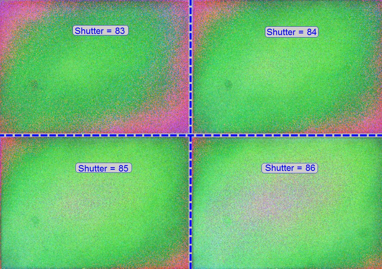
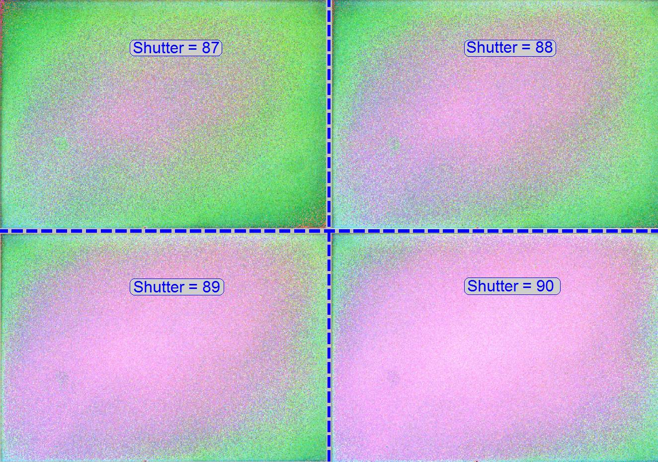
The following images show an
acceptable, finished LUT adjustment. The
shutter was increased in steps by one from 83 to 90; Pannoramic SCAN, Marlin
camera and 1.0x camera adapter.
To check or adjust the white balance
leave the LUT by uncheck the checkbox “LUT operation on”.
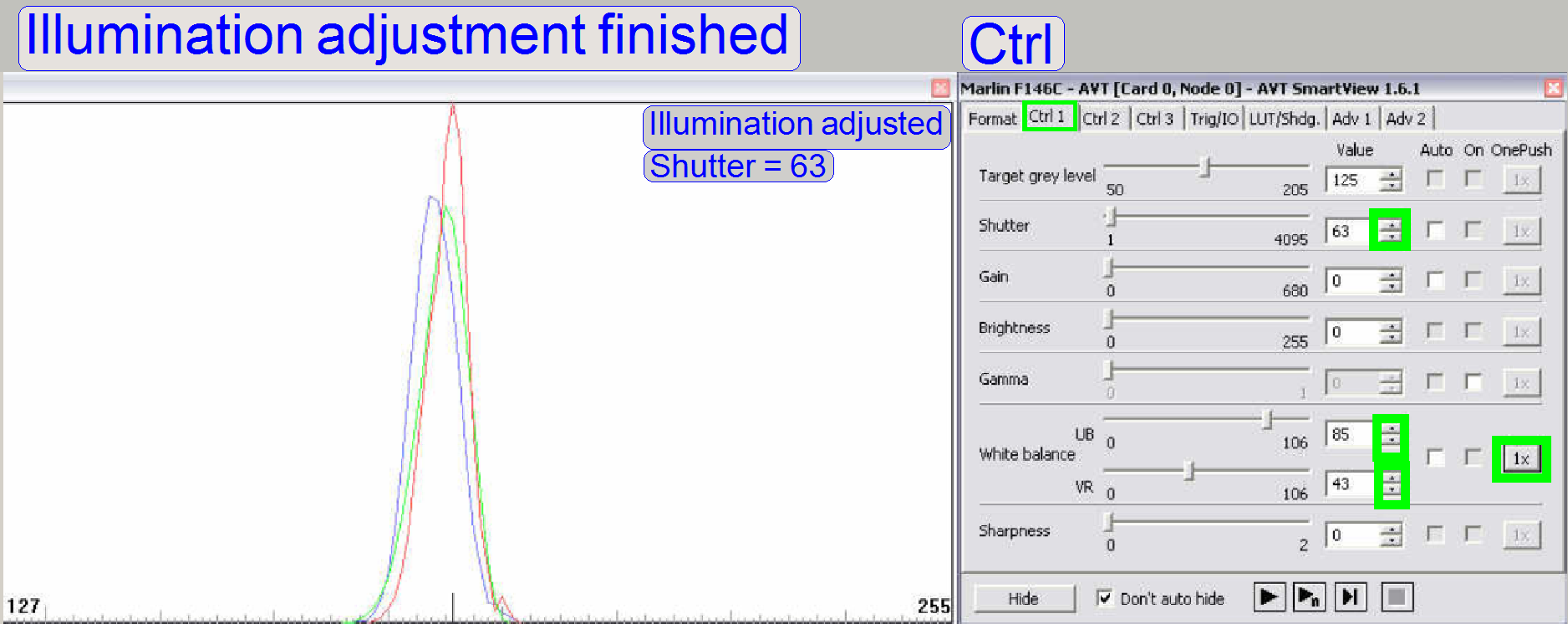 The same scanner with adjusted illumination and a shutter
value of 63. Peaks in the functions should be eliminated (or as little as
possible).
The same scanner with adjusted illumination and a shutter
value of 63. Peaks in the functions should be eliminated (or as little as
possible).
To eliminate peaks in the functions
you can also adjust the condenser position carefully again.
Remark
The reachable result depends highly on
the used marlin camera (variance of the product) and the quality of the
selected field of view (clean FOV).
The entire image path adjustment
includes the adjustment of the following parts:
1. The objective
position
This
adjustment ensures that tissues with different thicknesses can be scanned in
focus; of course, it was adjusted previously for the brightfield illumination,
but the objective position should be checked and adjusted again. If the
objective position is incorrect, the tissue or parts of it can not be scanned
in focus; see also “Check the optical path adjustments”.
2. Camera tube
position
The
position of the camera tube (lens) affects the color trueness of the scanned
tissue; the chromatic aberration becomes visible in more blue, and more red or
yellow colored cell borders on the opposite sides; see also “Chromatic
aberration” and “Adjustments”.
3. Camera rotation
angle
If
the camera rotation angle is out of the limits, the stitching is not correct and
the borders of the FOV’s becoming visible in the virtual tissue with the viewer
program, the sample does not fit on the border of the FOV; see also
“Stitching’.
The appearance of chromatic aberration can be
divided into two main reasons:
1.
The used materials (the composition of the glass) in
the lens system; different wavelengths of light will be focused to different
positions; and
2.
The arrangement of the lenses to each other
(centermost), with other words, the straightness of the optical path (lens
system).
· For any kind of
optical aberration see “Optical
aberrations”
Chromatic aberration of a FOV is seen as unevenly colored cell borders.
Because the first item is given by the used optics (the
construction of the objective and lenses) and can not be affected by the
technician, we minimize the chromatic aberration by making the optical path straight
and centered.
For this purpose, in the SCAN and the
After the chromatic aberration adjustment was finished, the camera rotation angle
has to be adjusted (again).
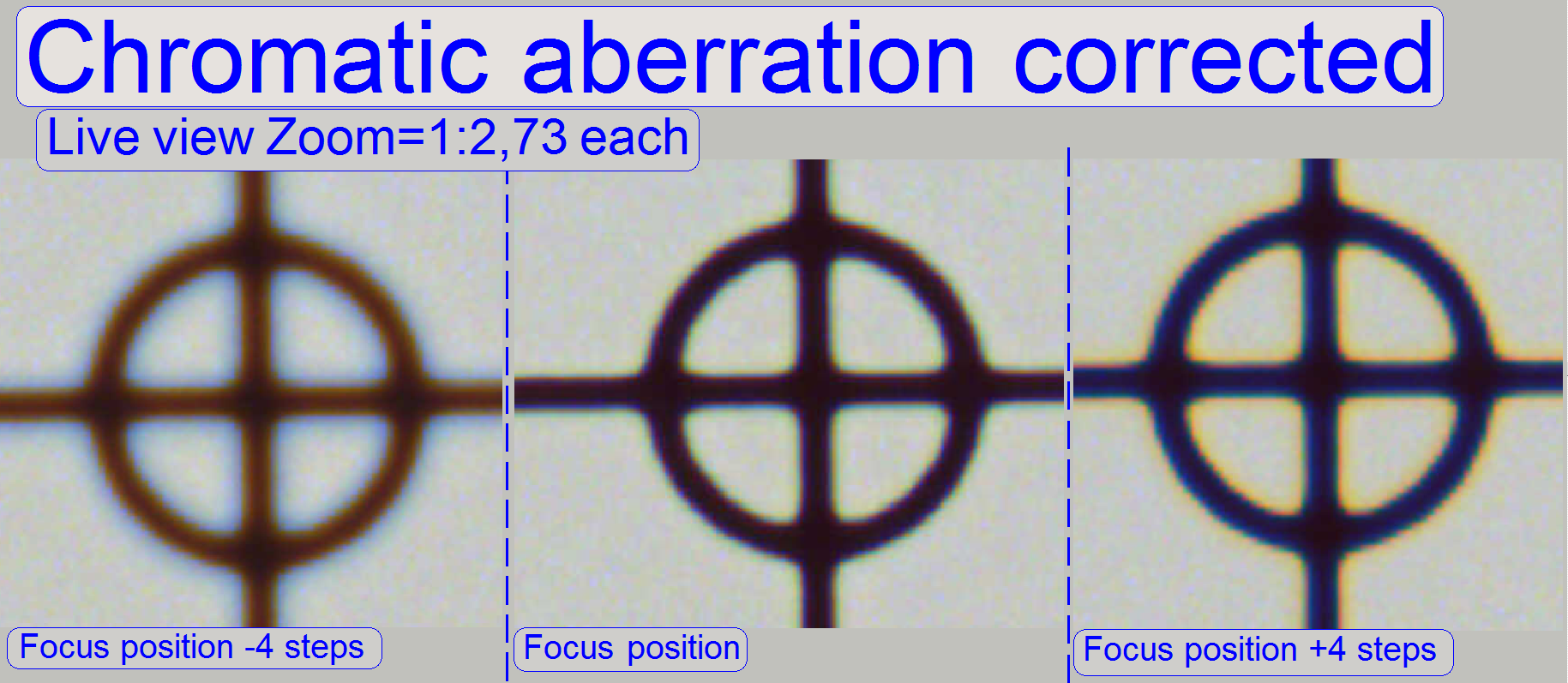
The adjustment of the chromatic
aberration is done in the real focus position and in the center of the FOV to
be observed. To check the result of the adjustment, the focus position can be
modified by some steps in positive or negative direction. In this way, the
correctness of the adjustment becomes more visible. If the yellow color occurs
evenly on the inner and outer part of the circle in the center, the adjustment
is acceptable; see “Focus position +4 steps”.
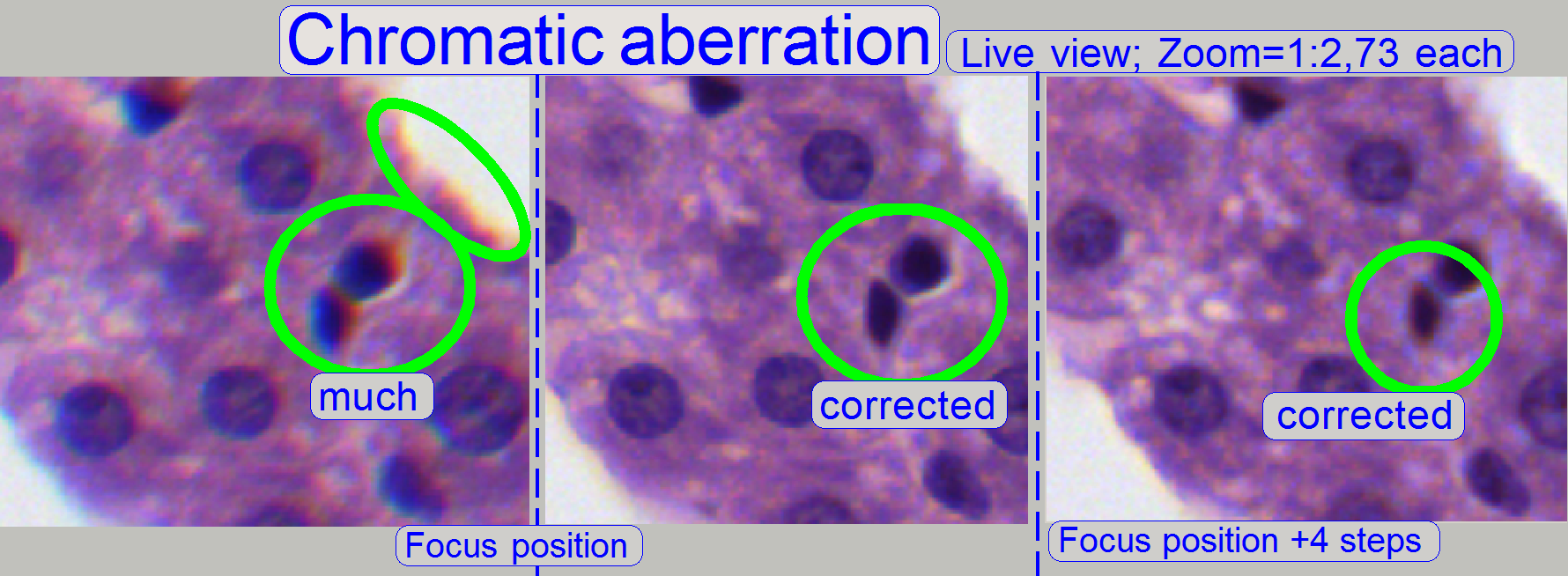
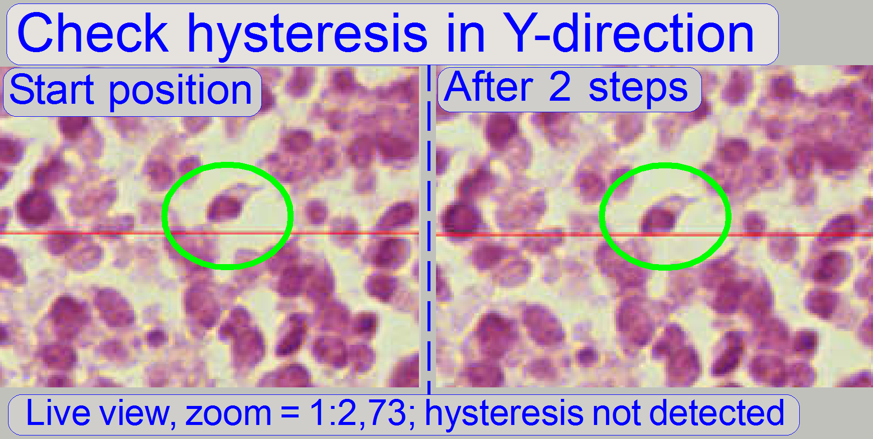
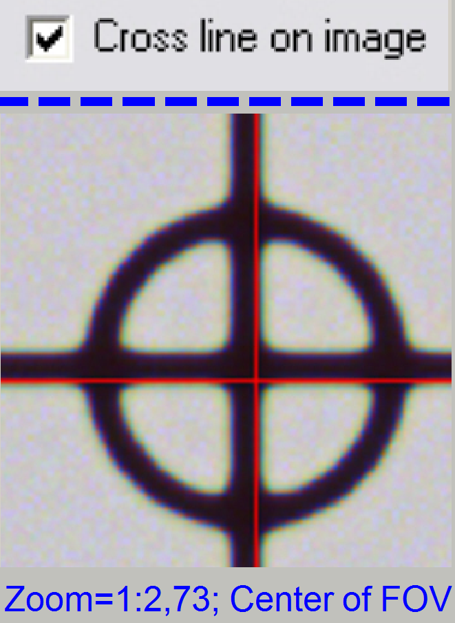
The images was done in the focus
position of the live view, except otherwise specified and with a zoom factor of
2,73
Reduce the chromatic aberration
 Chromatic
aberration becomes visible if the optical light path is not exactly
perpendicular (mirrors) or centered (lenses); it is corrected by different
positioning of the tube. For this purposes use a well visible tissue. This adjustment assumes that the LUT adjustment is
already finished! To adjust the chromatic aberration use and observe always the
center of the FOV, never the border, because the border has always more
chromatic aberration as the center!
Chromatic
aberration becomes visible if the optical light path is not exactly
perpendicular (mirrors) or centered (lenses); it is corrected by different
positioning of the tube. For this purposes use a well visible tissue. This adjustment assumes that the LUT adjustment is
already finished! To adjust the chromatic aberration use and observe always the
center of the FOV, never the border, because the border has always more
chromatic aberration as the center!
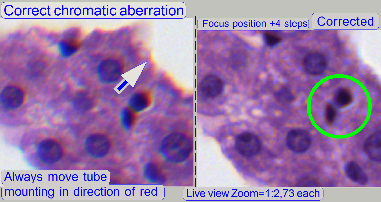
Example: If the otherwise dark spots in the tissue have
blue boundaries on the top, and red or yellow on the bottom (see also above “Chromatic aberration”),
move the tube to the red (yellow) direction.
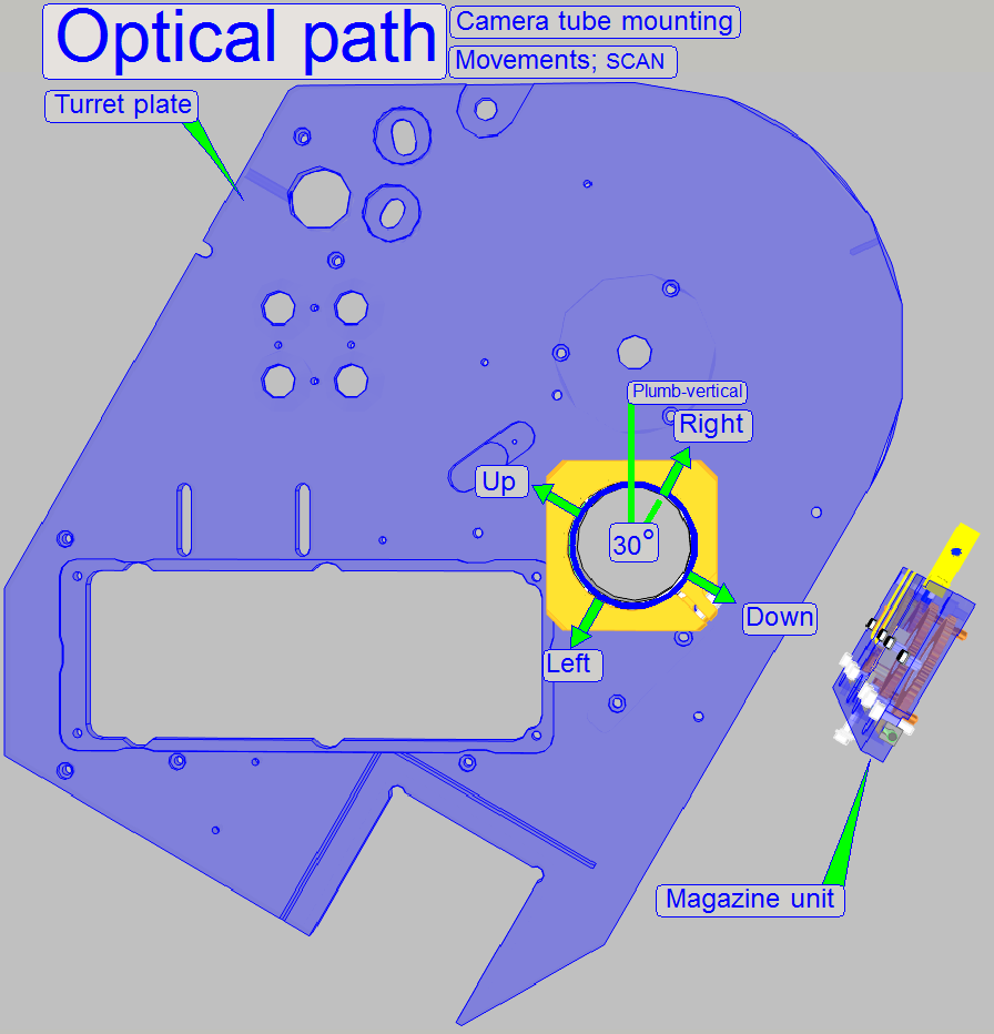
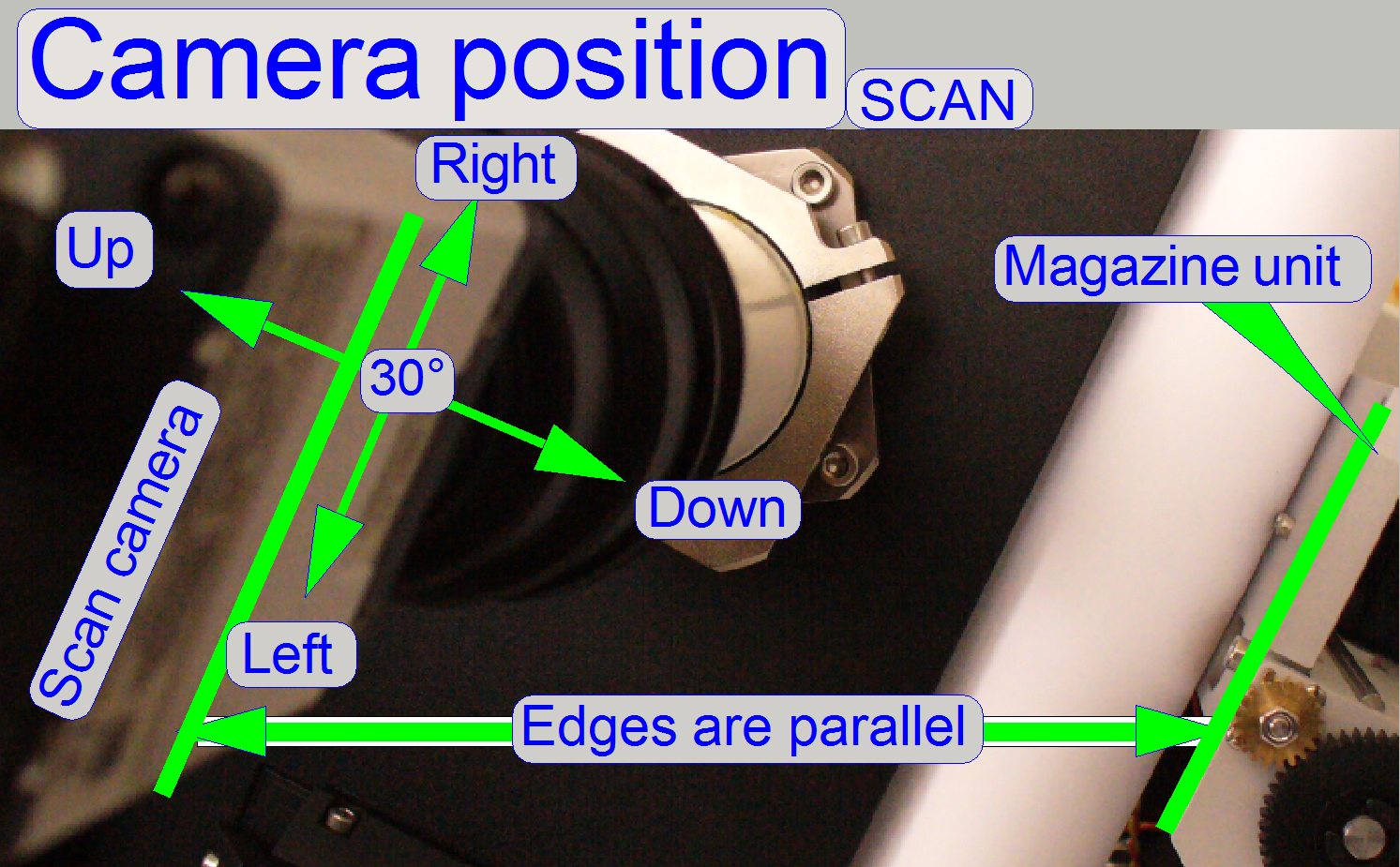
For Pannoramic SCAN: Keep in
mind, that the camera is mounted 30° from the plumb-vertical, therefore the
directions up, down, left and right are also turned 30° with respect to the
room’s coordinates; see “The camera angle”.
![]() Reduce the chromatic aberration
Reduce the chromatic aberration

1.
Start the program “SlideScanner.exe” and load a slide
with tissue.
· Important: Check the proper position of the slide in the specimen
holder.
2.
After the preview is done, select the option Focus and
click on the button “Live view”, positioning tool ![]() and click inside the tissue and find a well
usable FOV with a lot of cells. Use the “Auto focus” button.
and click inside the tissue and find a well
usable FOV with a lot of cells. Use the “Auto focus” button.
3.

 Fit the camera
view to window size with the button 1:1 and zoom in by using the zoom tool
until a zoom value of 2,73 is reached. By moving the horizontal and the
vertical scroll bar to the middle of their acting range, the center of the FOV
is in the center of the screen.
Fit the camera
view to window size with the button 1:1 and zoom in by using the zoom tool
until a zoom value of 2,73 is reached. By moving the horizontal and the
vertical scroll bar to the middle of their acting range, the center of the FOV
is in the center of the screen.
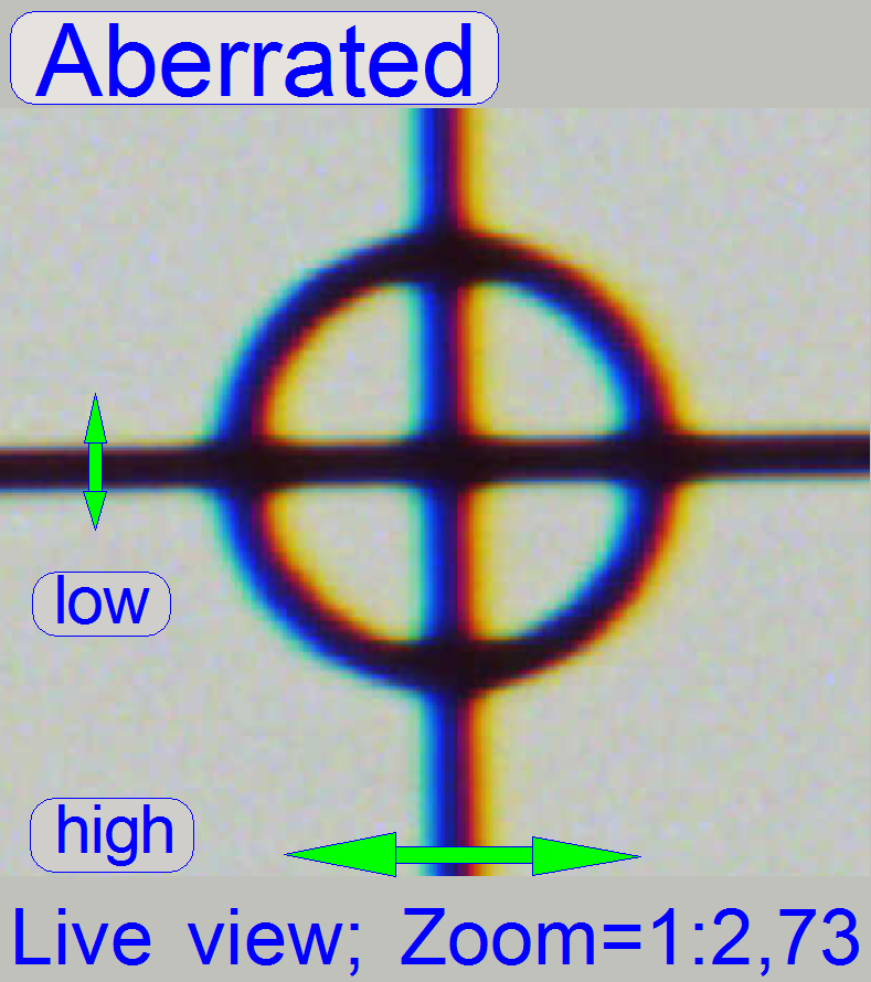
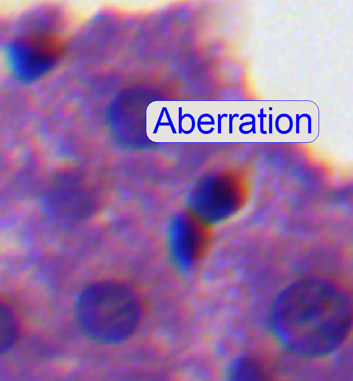
4.
 If the zoom value
is large enough (between 2.6 and 3), you can see something like this
“Aberration”. If yellow, red or brown colors are visible at the boundaries of
spots, the optical system has chromatic aberration; check this behavior on
different positions of the tissue also.
If the zoom value
is large enough (between 2.6 and 3), you can see something like this
“Aberration”. If yellow, red or brown colors are visible at the boundaries of
spots, the optical system has chromatic aberration; check this behavior on
different positions of the tissue also.
Procedure for SCAN and
5.
Loosen the tube fixing bolts
until the tube becomes just barely moveable.
6.
Move the tube in the direction, where the red or
yellow color of the spot or cell occurs. (With the Pannoramic SCAN: Take into
account, that the camera is mounted parallel to the magazine loader edge (30
degrees), so that the directions up, down, left and right are also turned 30
degrees; see also “Camera
rotation angle”. Remember, the chromatic aberration will be adjusted
always in the center of the field of view!
7.
 After pressing the
button “auto focus”, use a focus step size of 2 steps and go from the auto
focus position in plus direction. If the cell gets a brown or yellow ring in
nearly constant thickness the aberration seems to be adjusted.
After pressing the
button “auto focus”, use a focus step size of 2 steps and go from the auto
focus position in plus direction. If the cell gets a brown or yellow ring in
nearly constant thickness the aberration seems to be adjusted.
8.
Repeat step 7 and check this result on different
positions of the same slide (tissue) with live view.
9.
Scan a tissue or a part of it and check the result
with the SlideViewer. When you can find more positions where the aberration is
visible always on the same side of the cells, repeat from step 6 (if DESK then
from step “b”).
10.
When you can find parts of the tissue where the
chromatic aberration is visible on different sides of the spots, the chromatic
aberration seems to be adjusted.
11.
Scan two further tissues with different samples and
check the results (repeat the steps 9, 10).
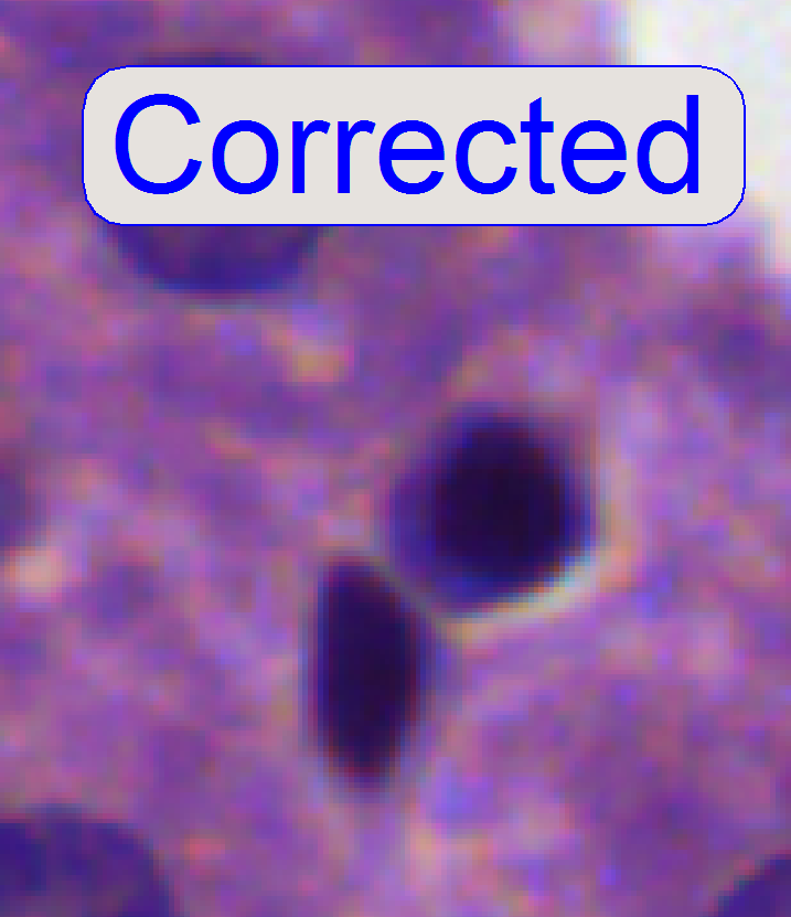
12.
If the boundaries of the spots (see “corrected”) are
colored evenly the optical path is correct.
13.
Tighten the tube mounting bolts and check the result,
by repeating the steps 7 to 10. If necessary, repeat the steps from step 5.
14.
Before scanning tissues the scan program
“SlideScanner.exe” has to be restarted, otherwise stitching errors may occur.
 After the
chromatic aberration adjustment was finished, the camera rotation
angle has to be adjusted (again).
After the
chromatic aberration adjustment was finished, the camera rotation
angle has to be adjusted (again).
 With this adjustment, the chromatic aberration can be
reduced in the vertical (Y) direction only. If the aberration in the
X-direction (left- right) is significant, the image mirror position must be
adjusted; see below “Image mirror position adjustment”.
With this adjustment, the chromatic aberration can be
reduced in the vertical (Y) direction only. If the aberration in the
X-direction (left- right) is significant, the image mirror position must be
adjusted; see below “Image mirror position adjustment”.
a.
Do the steps 1
– 4 as described above.
b.
Loosen the
mirror tube mounting bolt.
c.
Loosen the
aberration adjustment bolt fixing nut and drive the adjustment bolt backward
(CCW) some turns.
d.
Pull the mirror
tube in direction to the objective until it is stopped by the adjustment bolt.
e.
Observe the
live view and drive the adjustment bolt forward (CW).
f.
If the
chromatic aberration in vertical direction disappeared stop the adjustment.
g.
Tighten the
mirror tube mounting.
h.
Hold the position
of the adjustment bolt constant with the hex key wrench and tighten the
position fixing nut.
i.
To check the result,
continue the adjustment for SCAN and
Image mirror position
adjustment (DESK)
·
 Attention: If the
mirror position bolts are fixed with red glue, the correct position is adjusted
previously and the reason for the horizontal aberration may be elsewhere. Check
the tightness of all optical components first and the quality of the tissue!
Check also tissues with different thicknesses!
Attention: If the
mirror position bolts are fixed with red glue, the correct position is adjusted
previously and the reason for the horizontal aberration may be elsewhere. Check
the tightness of all optical components first and the quality of the tissue!
Check also tissues with different thicknesses!
·
Always check the
proper position of the slide in the specimen holder also.
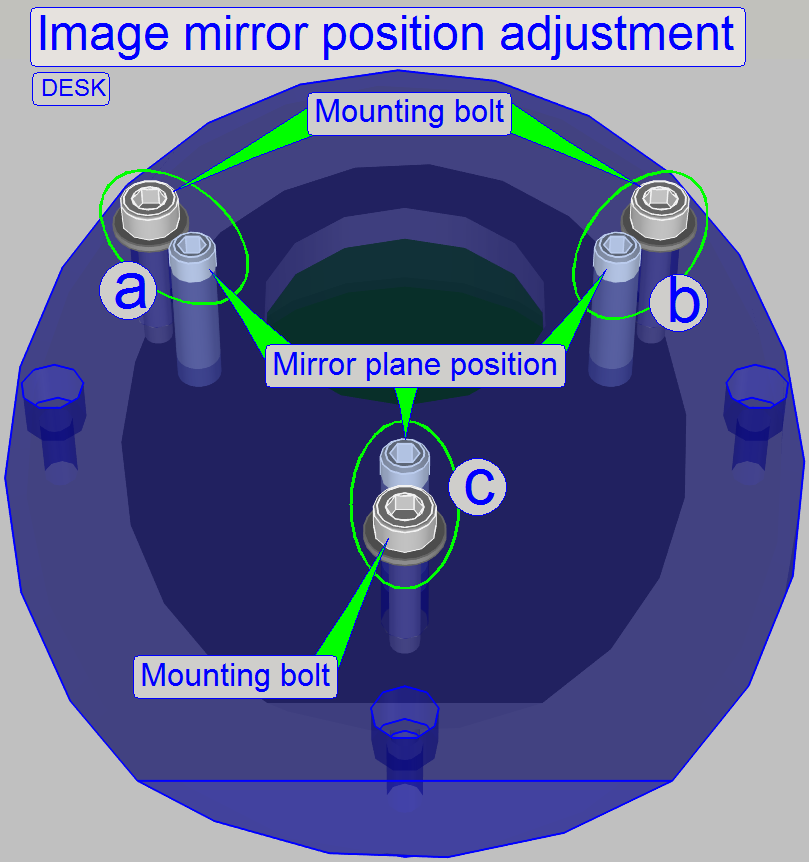
With this adjustment, the image mirror
can be positioned in the image path into the angle of exact 45 degrees in
relation to the objective and the tube lens; and so the chromatic aberration
will be minimized.
·
The bolt pairs
“a”, “b” and “c” defines the plane of the image mirror; “a” and “b” define the
angle of inclination mainly left or right and the bolt pair “c” defines the
angle of inclination mainly up or down.
·
By loosening
the mounting bolt of the appropriate bolt pair and driving in the plane
position bolt; or driving outward the plane position bolt and tightening the
appropriate mounting bolt, the mirror plane is modified.
·
Before checking
the result, all the mounting bolts should be tightened!
Adjust the image mirror plane
1.
Produce a well
usable live view as described above “Adjust the chromatic aberration”.
2.
Drive the
chromatic aberration adjustment bolt (see the image above, “Mirror tube”)
nearly into the middle of its adjustment range and pull the mirror tube toward
the objective until the adjustment bolt is reached.
3.
Modify the
position of the mirror plane by driving the bolt pairs “a”, “b” and “c” as
required and minimize so the chromatic aberration.
4.
Does the
chromatic aberration adjustment procedure as described above, see “Procedure for DESK”.
Stitching errors have two main
reasons:
1.
Improper
adjusted camera rotation angle and
2.
The hysteresis
in Y-direction is too much.
The camera angle becomes important during
stitching. If the angle of the scan camera is out of the limit, the stitching
does not working well, so the FOV’s, seen with the viewer does not fit to each
other. An acceptable camera angle has less then +-0.5 degrees deviation from
zero.
If the camera angle is correct and
stitching errors occur, check the hysteresis in Y-direction.
![]() next chapter “Y- and X-hysteresis”
and also “X-Y-stage unit”
next chapter “Y- and X-hysteresis”
and also “X-Y-stage unit”
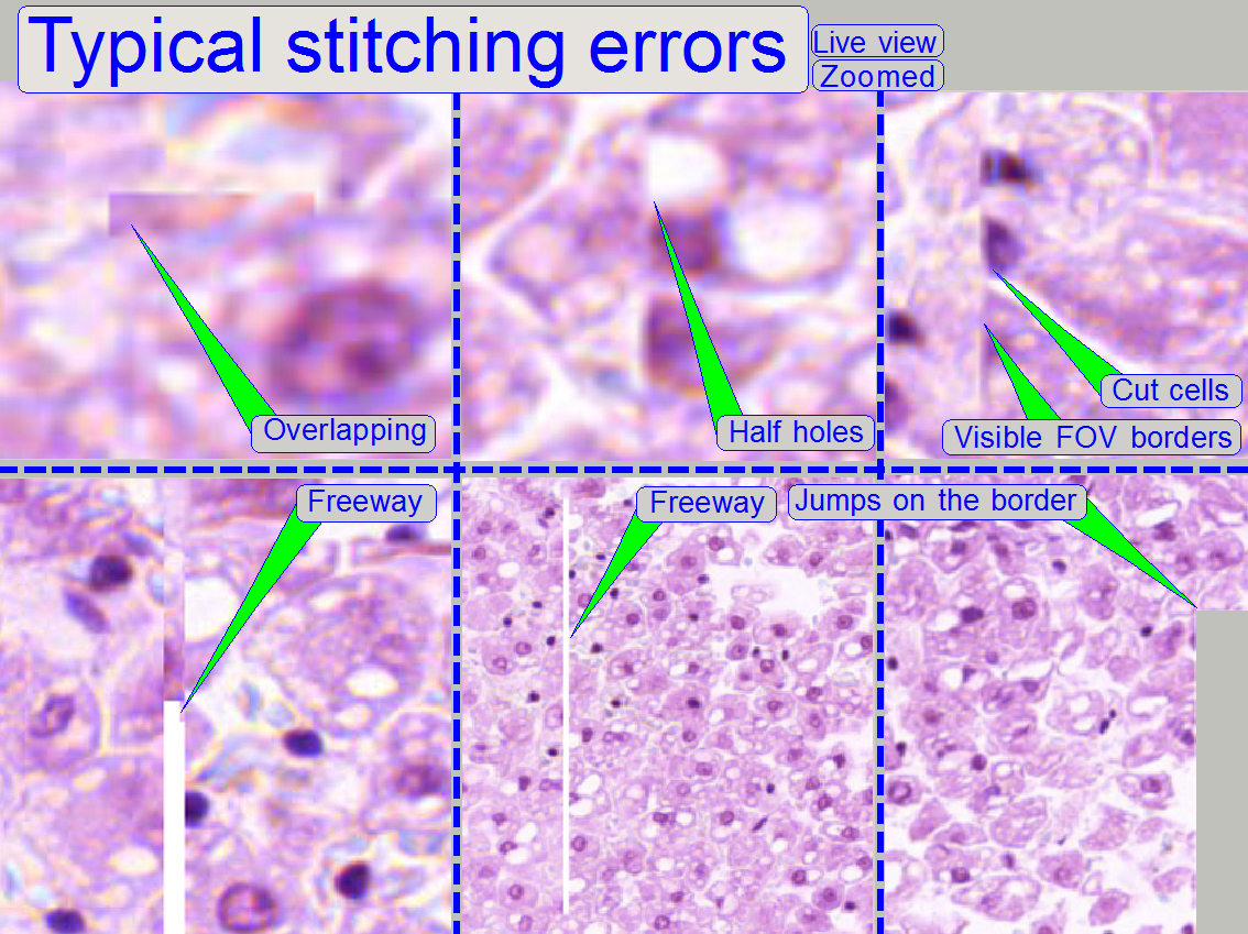
Remark
The shown stitching errors existing
always parallel inside of the same scanned tissue, it means, if one occurrence
is found, all others can also be found on different areas of the same scanned
tissue (if the scanned area is large enough).
Adjust the camera rotation angle
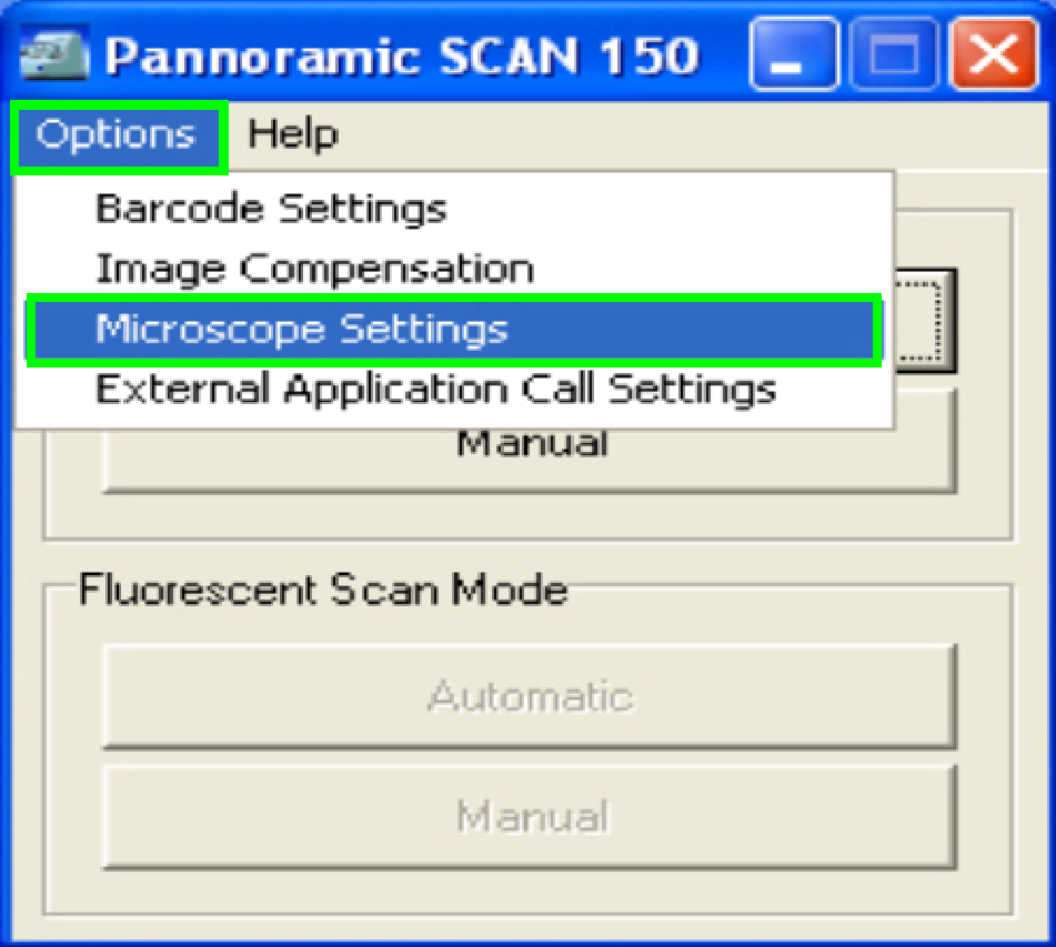 In the
selector menu and ‘Options” start the item “Microscope settings”.
In the
selector menu and ‘Options” start the item “Microscope settings”.
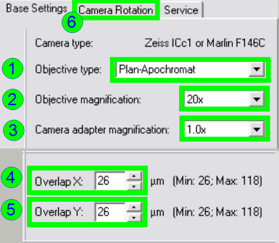 In the
tab “Base settings” set the values for the parameters numbered with (1)-(5) as
these are true for the scanner to be set up; then change to the tab “Camera
rotation” (6).
In the
tab “Base settings” set the values for the parameters numbered with (1)-(5) as
these are true for the scanner to be set up; then change to the tab “Camera
rotation” (6).
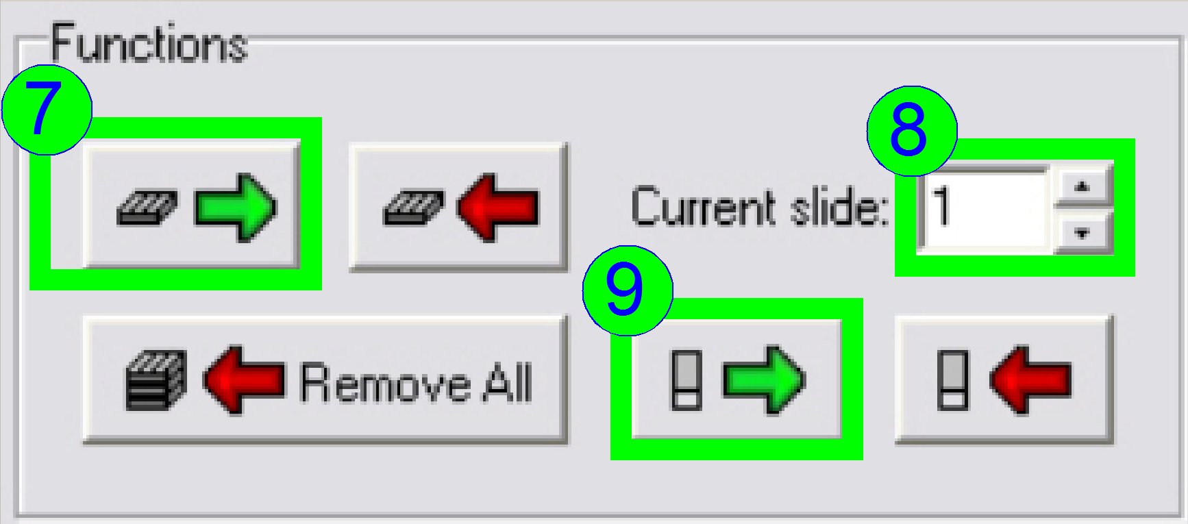 Load a
magazine (7), select the desired slide position (8) and insert the slide
(9).
Load a
magazine (7), select the desired slide position (8) and insert the slide
(9).
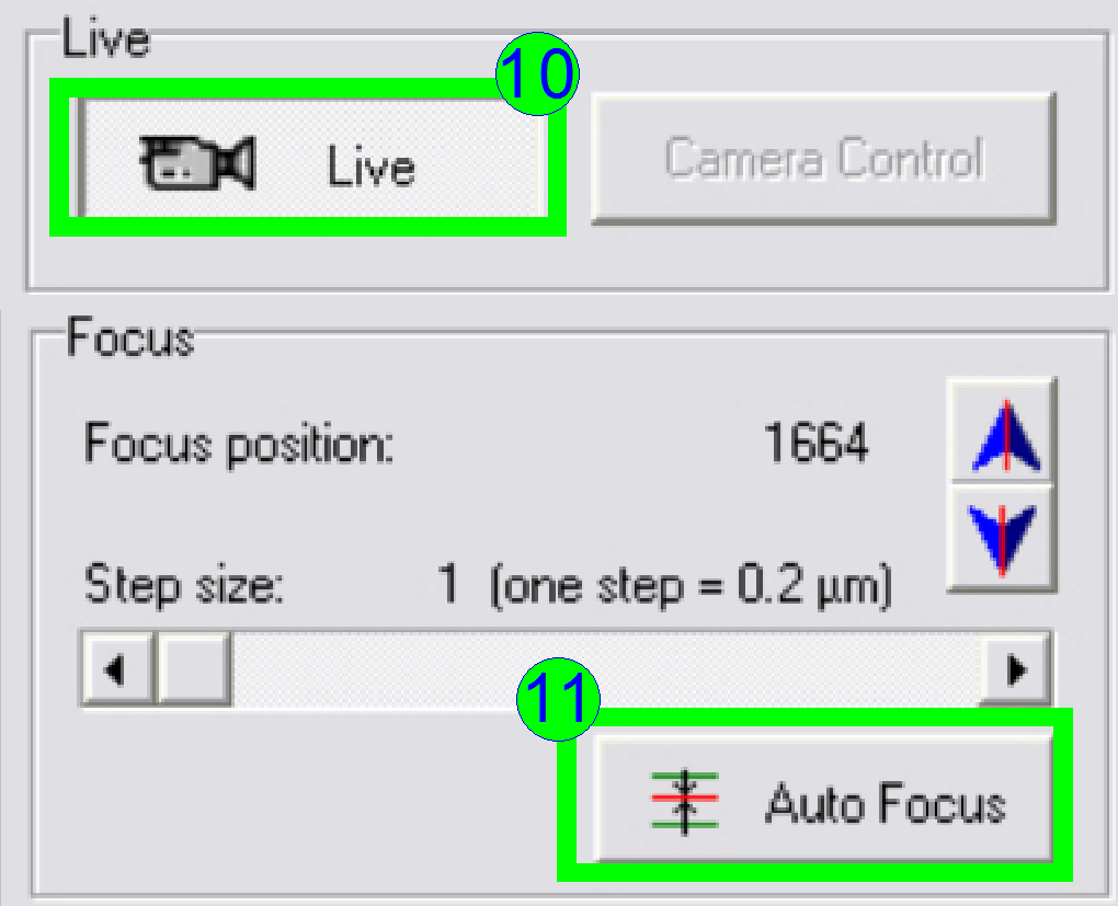 In the
preview window find a FOV with tissue, Press the button “Live view” (10) and
“Auto focus” (11). If the focus position is found, click outside the tissue and
inside the cover slip on a “white” position.
In the
preview window find a FOV with tissue, Press the button “Live view” (10) and
“Auto focus” (11). If the focus position is found, click outside the tissue and
inside the cover slip on a “white” position.
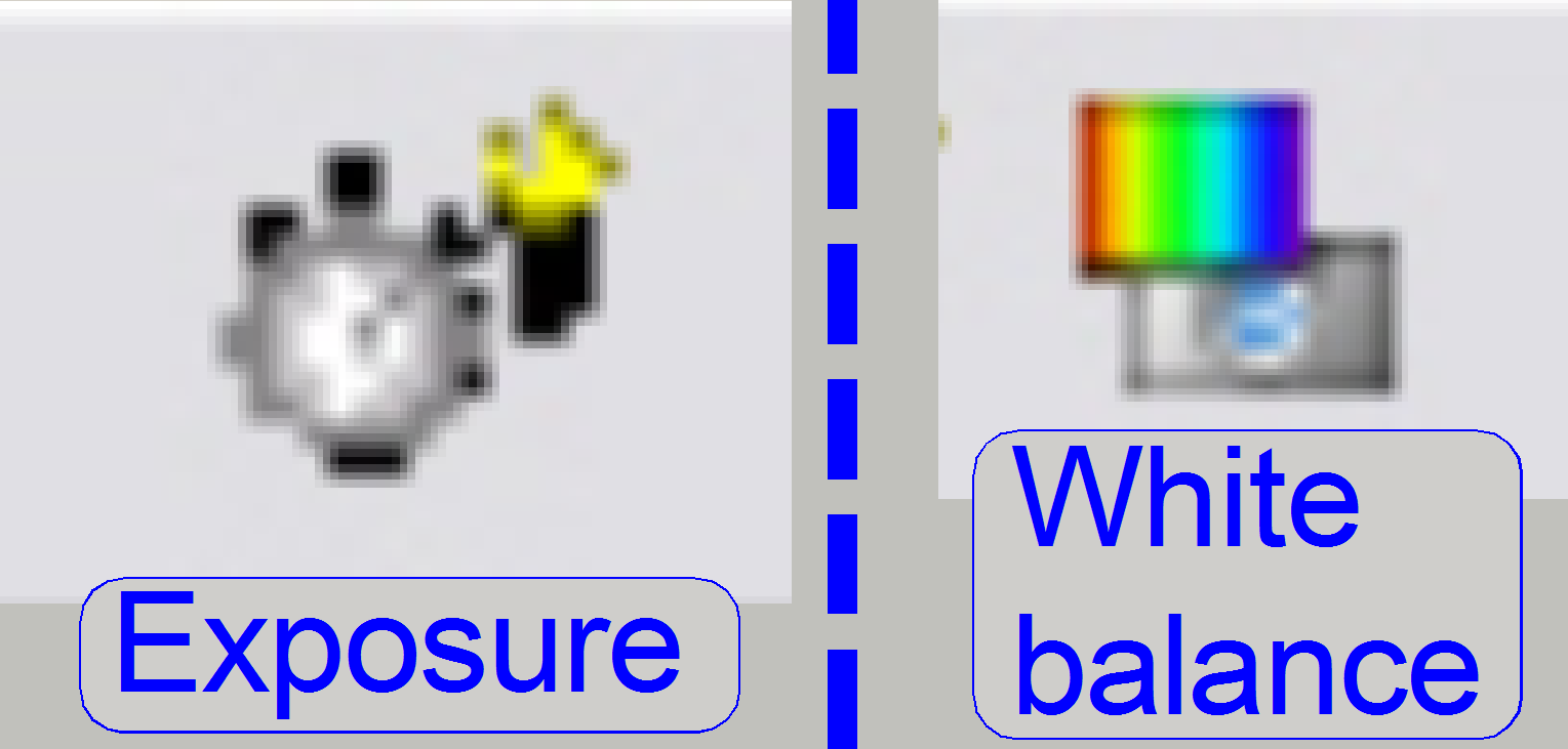 Set
the “Auto exposure time” and the “White balance” by clicking on the appropriate
icon on the lower screen border.
Set
the “Auto exposure time” and the “White balance” by clicking on the appropriate
icon on the lower screen border.
Click inside the tissue and find a well usable FOV with
cells.
Find the focus position (11).
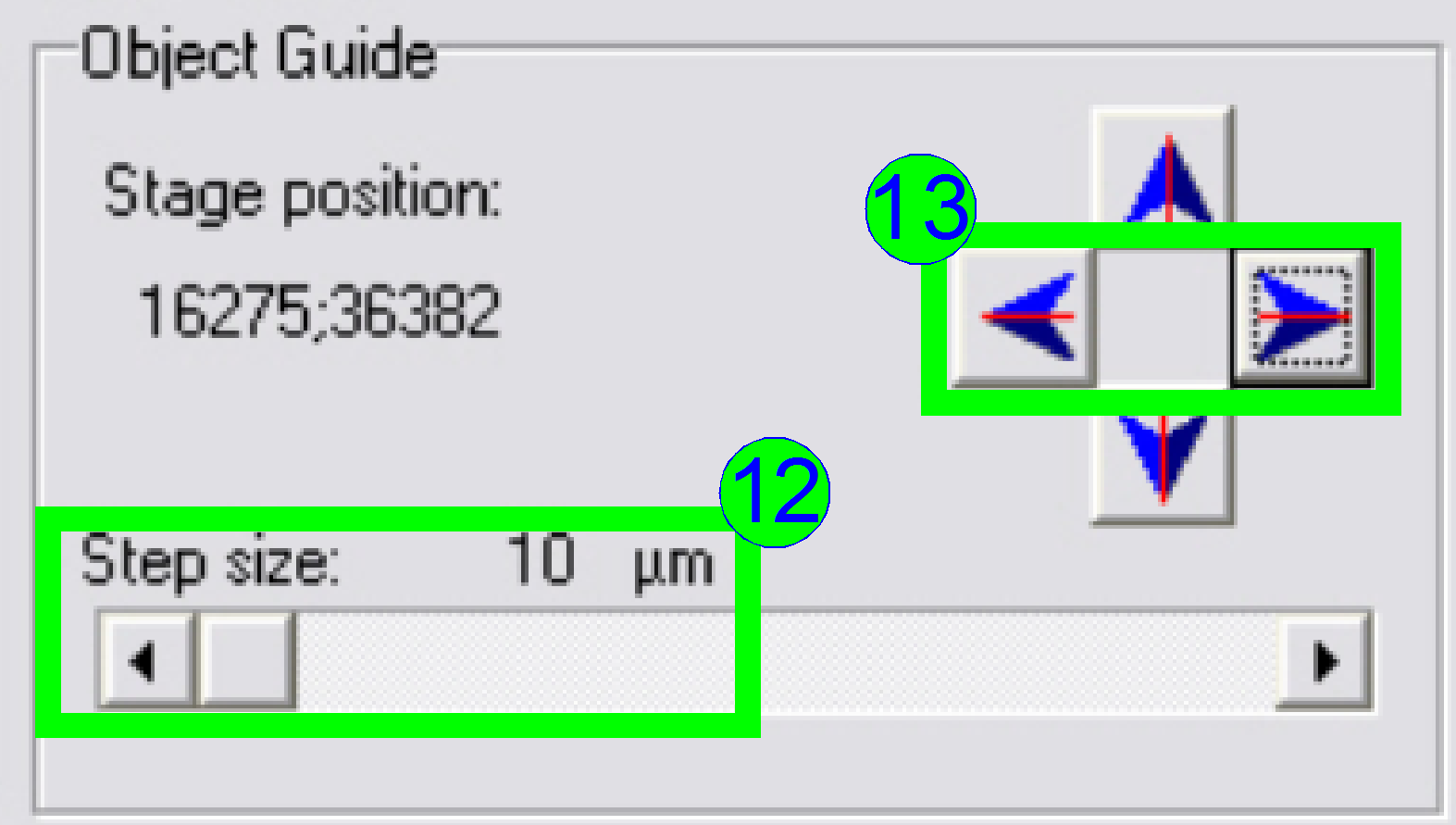 Select
a “Step size” of 10 or 20 µm (12) and move the object guide to the left or
to the right as desired (13) and observe the movement of a cell near to or on
the horizontal red line.
Select
a “Step size” of 10 or 20 µm (12) and move the object guide to the left or
to the right as desired (13) and observe the movement of a cell near to or on
the horizontal red line.
· If the
cell deviates from the red (horizontal) line in the center upward or downward
respectively, correct the camera angle continuously (by moving the camera
adapter on its mounting) until the cell moves on the red line (14) or exact
parallel to it.
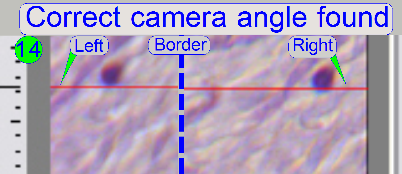 If the
cell moves from the left border to the right border of the screen (or reverse)
nearly on the red line, the camera angle is correct (14).
If the
cell moves from the left border to the right border of the screen (or reverse)
nearly on the red line, the camera angle is correct (14).

Press the button “Measure camera rotation” (15).
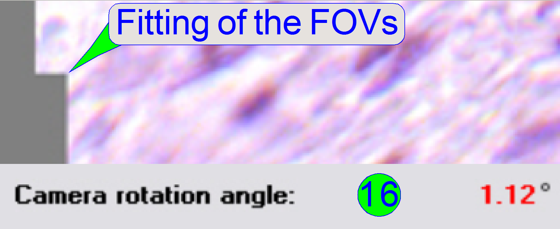 Now the
program arranges two FOVs to each other and shows so graphically the fitting of
the FOVs in the centre of the live view; the numerical value of deviation is
shown in the lower part of the left sided adjustment window.
Now the
program arranges two FOVs to each other and shows so graphically the fitting of
the FOVs in the centre of the live view; the numerical value of deviation is
shown in the lower part of the left sided adjustment window.
· If the
value of the rotation angle is shown in red, the position must be adjusted more
precise (16). Correct the camera position and press the button “Measure camera
rotation” (15) again, until an acceptable angle is found.
· An
acceptable camera rotation angle has less than 0.5degrees deviation from zero.
 If the
rotation angle can be accepted, the angle value is shown in black (17).
If the
rotation angle can be accepted, the angle value is shown in black (17).
 Save
the calculated rotation angle to the appropriate file by pressing “Save” (18);
and in the next following dialog answer with “YES” to save the file.
Save
the calculated rotation angle to the appropriate file by pressing “Save” (18);
and in the next following dialog answer with “YES” to save the file.
Leave the menu “Options” by clicking on “Exit”.
Check
the optical path adjustments
As discussed previously, the correct objective and focus
position is important to be able to scan tissues of different thicknesses in
focus.
This fact we are using to determine the correct
objective position.
1. Find
at least three, better are 5 slides with tissue of different thickness and of
different kind.
2. Insert
the (next) slide; check the correct position of the slide in the specimen
holder!
3. Produce
a live view of the tissue, press “Autofocus” and notify the focus position.
4. Repeat
step 3 on 5 different positions of this tissue; the distance of the positions
should be as much as possible.
5. Calculate
the average focus position of this slide and notify it.
6. Repeat
from step 2 until the average focus position of all the selected tissues is
determined.
7. Calculate
the average focus position of all the tissues.
8. If the
average focus position deviates more then 50 steps from the nominal focus
position, calculated with the used slide thickness, the objective position
should be corrected.
9.
If the objective position was modified,
please check the correctness of the condenser position again.
 Check
the correct condenser position in the focus positions 1200, 1600 and 2000
steps. There must not be significant differences.
Check
the correct condenser position in the focus positions 1200, 1600 and 2000
steps. There must not be significant differences.
· For best
scan results, the clean FOV should be evenly illuminated over the entire focus
range.
· If the
condenser is misaligned, the roughly surface of the diffuser becomes visible!
Remark
“Clean FOV” means a Field of View, seen by the scan
camera without tissue, dust or dirt, between slide and cover slip.
![]() “Adjust the
condenser position” and “Focus
unit”
“Adjust the
condenser position” and “Focus
unit”
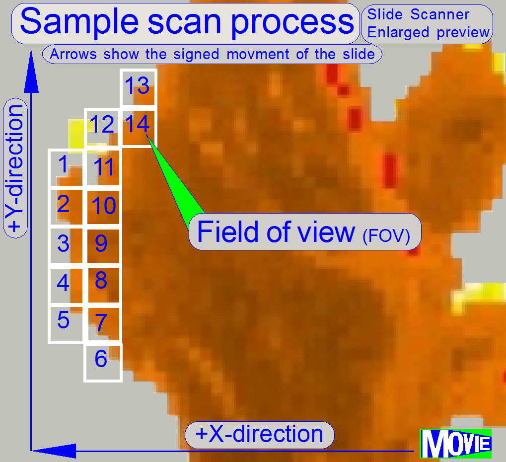 The software divides the sample to
be scanned, seen by the preview camera into fields of views; the size of the
FOV depends on the resolution and the size of the scan camera’s CCD and the
magnification of the camera adapter. Each field of view contains a small part
of the neighbor FOV. In this way, stitching becomes possible. Because the
capturing of the FOV’s is done on a meandering course, the Y-direction is often
changed. If the hysteresis in Y-direction is too much, stitching will not work
correctly; therefore, we have to check the hysteresis in Y-direction. The
maximal allowed hysteresis is
The software divides the sample to
be scanned, seen by the preview camera into fields of views; the size of the
FOV depends on the resolution and the size of the scan camera’s CCD and the
magnification of the camera adapter. Each field of view contains a small part
of the neighbor FOV. In this way, stitching becomes possible. Because the
capturing of the FOV’s is done on a meandering course, the Y-direction is often
changed. If the hysteresis in Y-direction is too much, stitching will not work
correctly; therefore, we have to check the hysteresis in Y-direction. The
maximal allowed hysteresis is
Because the X-direction is never changed during a
sample scan process, the X-hysteresis is not critical and can be some steps
more (max: 8 steps).
· To
reduce the Y-hysteresis, see also “X-Y-stage unit”
and “X- and Y-carriage
drive unit”.
Watch video: “Tissue scan process” (P250)
Check
the maximal hysteresis in Y-direction
Start the program “SlideScanner.exe” with the service
password. In the tab “Focus” produce a sharp life view.
In the tab “Service” select “Microscope control”. In
the part of the X-Y-control select a step size of two steps and go upward,
until the tissue moves.
Now go in opposite direction and count the clicks
until the tissue moves again. If more then 3 clicks are required, the
hysteresis is too much.
The correction of the hysteresis can not be done in
the field.
Scan a tissue and check the chromatic aberration with
the Slide Viewer program.
Scan a tissue and check the stitching with the Slide Viewer
program for stitching errors. See also “Typical stitching errors” in the
chapter above.
 The
stage skew check is used to determine the inclination of the specimen holder
and so the inclination of the slide. If the inclination is too much, parts of
the tissue are in focus during other parts of the same FOV are not in focus.
The
stage skew check is used to determine the inclination of the specimen holder
and so the inclination of the slide. If the inclination is too much, parts of
the tissue are in focus during other parts of the same FOV are not in focus.
The Stage skew check should be done:
- If the parallelogram was removed.
- If the parallelogram or the specimen holder was exchanged.
- If the entire X-Y-stage unit was changed.
- If the Focus unit was exchanged.
- If any spare part was changed and this spare part is in connection
with the perpendicularity of the optical axis to the slide.
- If the mounting bolt positions or the adjustment bolts position of
the parallelogram was altered.
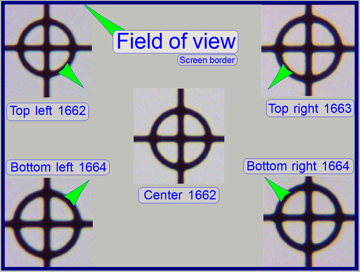
To check the inclination angle of the specimen holder,
a series of screen shoots is done of a cell (circle) in the center of the FOV
and in the upper and lower and left and right corners respectively.
There are 7 screenshots taken in each position; 3
before the found auto focus position and 3 screenshots after the auto focus
position. Then find the screenshot of each position where the cell (circle) is
most in focus. If there is a difference, more then 2 focus steps to the found
focus positions, the specimen holder is slanted and has to be adjusted; this
adjustment can not be done in the field; probably the specimen holder or the
parallelogram is deformed.
Important: Always check the
proper position of the slide in the specimen holder first.
In the example on the right the most difference is 2
steps and therefore the inclination of the specimen holder is acceptable.
1.
Start the program SlideScanner.exe with
the service password, insert the slide with circle, produce a live view and
press auto focus.
·
Important: Always check the proper
position of the slide in the specimen holder.
2. Find
the circle and bring it nearly into the center of the live view, press auto
focus.
3. Select
the tab “Service” and “Microscope control”.
4. Select
a step rate about 5 or 10 steps for the object guide.
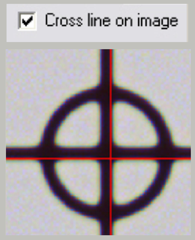
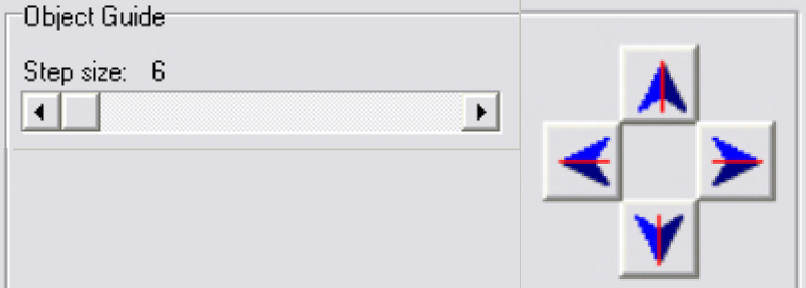 5. Check
the checkbox “Cross line on image” and with the object guide movement buttons
bring the center of the circle to the center of the cross; the circle is now in
the center of the FOV.
5. Check
the checkbox “Cross line on image” and with the object guide movement buttons
bring the center of the circle to the center of the cross; the circle is now in
the center of the FOV.
6. Uncheck
the checkbox “Cross line on image”
7. Zoom
in until a value of 2,73 is reached.
8. Grab
the center of the circle (FOV) into the middle of the screen.
9. Memorize
the auto focus position and go backward with the focus position about 20 steps;
and then go forward to the auto focus position -3 steps with a step size by 1.
This way, the probably hysteresis of the focus unit and other mechanics is
eliminated.
10. Make a screenshot
and create a directory named “Focus stack”, name the file as C (for center) and
the number of the actual focus steps, e.g. “C 1659” if the
memorized focus position was 1662 steps and save the file into the directory
“Focus stack”.
 11. Increment the focus
position by 1, make the next screenshot and save the file.
11. Increment the focus
position by 1, make the next screenshot and save the file.
12. Repeat step 11
until all the 7 screenshots are done.
13. Now move the
circle with the object guide positioning buttons to a corner position, e.g. to
the upper left corner. The corner is found correctly if the circle can not be
grabbed in direction to the center (see also the green arrows in the image
above “The field of view”).
14. Repeat the steps
from step 9 logically until the screenshots are done in all four corners. The
file names should be TL xxxx, BL xxxx, TR xxxx and BR xxxx (for Top Left and so on).
Find the screenshot with the circle most in focus for
each series and notify the file names.
Decide the specimen holder has either to be adjusted
or not as shown in the image above “The field of view”).
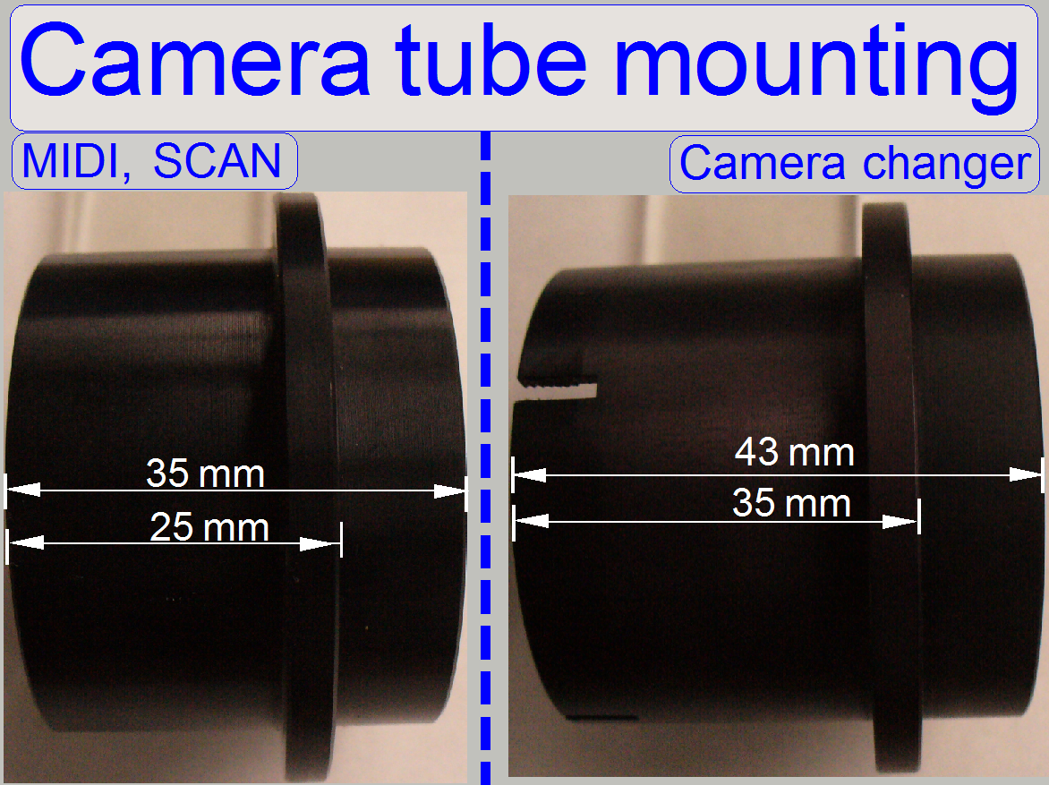
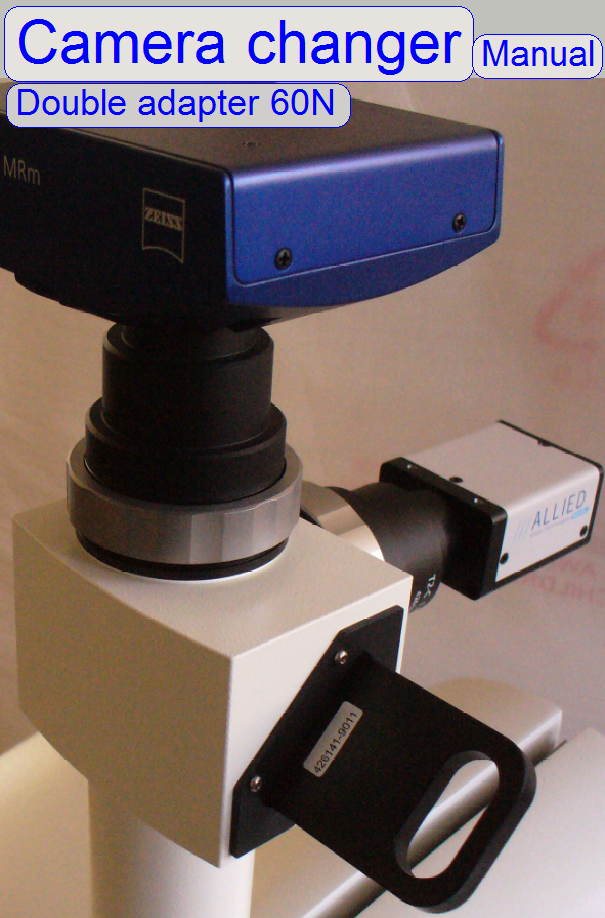 The camera changer (the double adapter 60N is a
product of Carl Zeiss ltd.) allows the use of different cameras for brightfield
illuminated scan and fluorescent illuminated scan sessions; it may be a
component of the Pannoramic SCAN or the Pannoramic MIDI scanner likewise.
The camera changer (the double adapter 60N is a
product of Carl Zeiss ltd.) allows the use of different cameras for brightfield
illuminated scan and fluorescent illuminated scan sessions; it may be a
component of the Pannoramic SCAN or the Pannoramic MIDI scanner likewise.
Since software version 1.14 both
cameras are installed at the same time and recognized by the scan software. If
we are changing the scan mode from brightfield to fluorescent mode or vice
versa in the software (the appropriate camera driver will be selected), the
appropriate camera can be selected manually also; without further adjustments
or the change of the configuration.
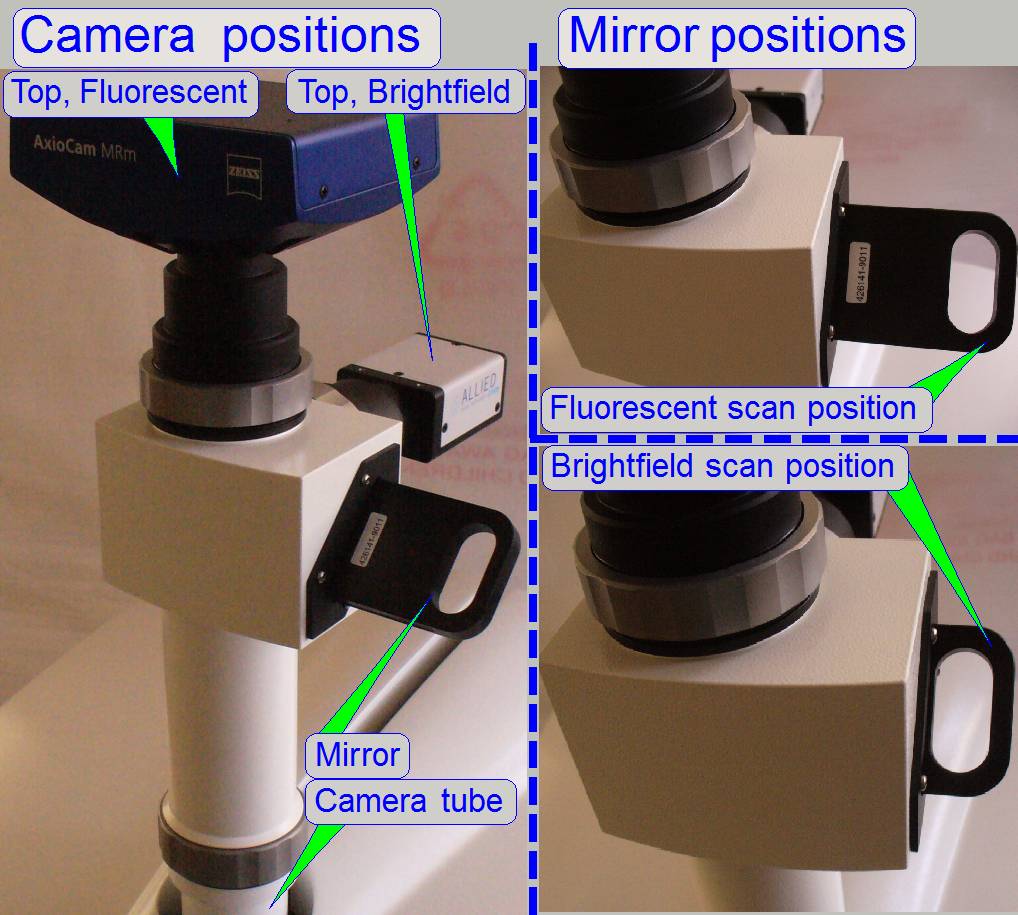
The exchange of the camera is done
by a mirror. In practice, not the camera will be exchanged, the image path is
deflected by the use of the mirror by 90 degrees (if the mirror is inserted) or
the image path goes straight, if the mirror is removed (in outer position). To
reach the correct image path, the mirror mechanics has two, an inner and an
outer click stop position.
Because the quantity of light is
very low in the fluorescent mode, the camera, used for fluorescent mode should
be mounted so, that the mirror is not in use; with other words, if the mirror
is inserted into the image path, the camera, used for brightfield illumination
should be selected.
Adjustments
 The mounting position of the camera changer unit
affects the camera rotation angle only; therefore we suggest doing all other
adjustments (chromatic aberration, stage skew check ...) without camera changer;
the camera changer should be mounted if all other adjustments are already
finished.
The mounting position of the camera changer unit
affects the camera rotation angle only; therefore we suggest doing all other
adjustments (chromatic aberration, stage skew check ...) without camera changer;
the camera changer should be mounted if all other adjustments are already
finished.
·
Mount the
camera changer so, that the 60N interface for the brightfield scan camera shows
to the rear (
·
Mount the
camera adapters with the cameras.
·
Correct the
camera changer position as necessary.
·
Check the
tightness of all mountings.
·
Connect the
cameras with the appropriate cables to the computer and install the camera
drivers; see also “Usable
scan cameras”.
·
In the scan
program “SlideScanner.exe” define the cameras for brightfield scan and
fluorescent scan; see also “Usable scan cameras”.
·
Adjust the
camera rotation angle for the brightfield scan camera; see also “Adjust the camera
rotation angle”.
·
Adjust the
camera rotation angle for the fluorescent scan camera; see also “Adjust the camera
rotation angle”.