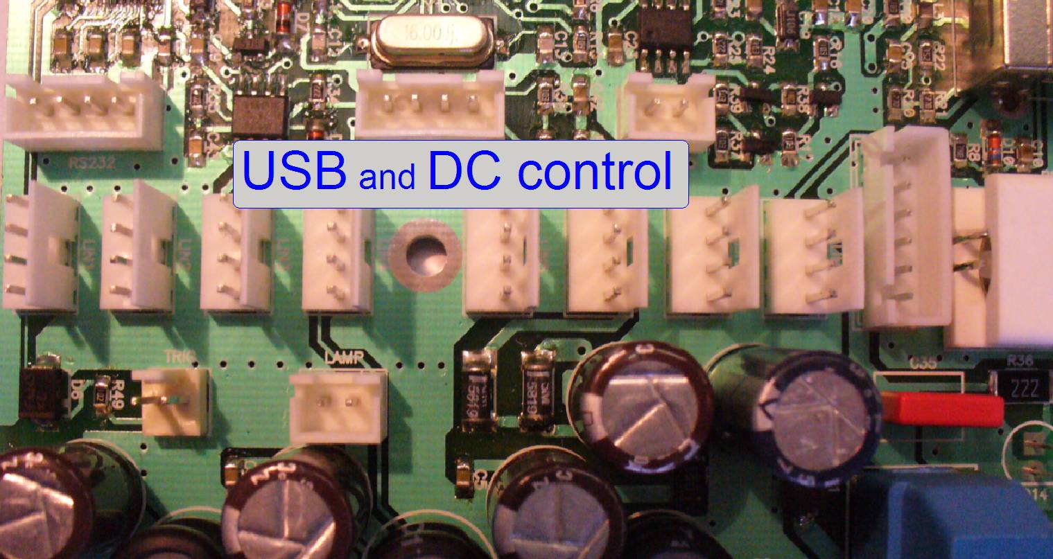
USB and DC control;
S_M_D
For technicians and partly for sales managers!
The following description handles the electronics and electrical
components and cabling, used in the Pannoramic scanners SCAN,
Differences are explained as they occur in the sequence.
Contents
Important remark
·
After maintenance or
services and performed tests of the scanner are 100% finished, protective
ground connections and other safety regulations related to hazardous voltages,
accessible conductive parts and dangerous to life parts have to be checked
(again).
·
For safety regulations regarding
human health and scanner functionality please refer to: Precautions
 The connected
power supply MPU
100-108 with an input voltage range of 100V~ to 240V~ AC and an output voltage
of 24V- DC supplies the motors and other internal units with power. Inside the
USB-controller, the DC-controller as well as in the stepper motor electronics a
local power supply is located and these create further, required voltages.
The connected
power supply MPU
100-108 with an input voltage range of 100V~ to 240V~ AC and an output voltage
of 24V- DC supplies the motors and other internal units with power. Inside the
USB-controller, the DC-controller as well as in the stepper motor electronics a
local power supply is located and these create further, required voltages.
·
The power switch can also be used to switch off the
entire scanner if mechanical jamming or any other emergency situation occurs!
Important
230V~
or 100V~
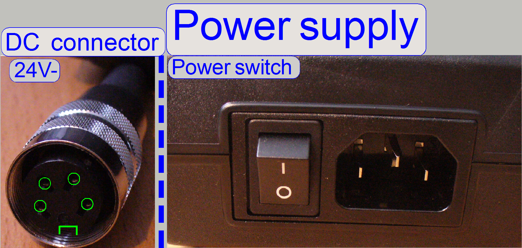 The alteration of
the mains power input in the range from 100V~ to 240V~ is reduced to the use of
the appropriate mains power cable!
The alteration of
the mains power input in the range from 100V~ to 240V~ is reduced to the use of
the appropriate mains power cable!
If the mains power is changed from 230V~ to 100V~ or vice versa, no alterations
are required inside the scanner; the change of the mains power is fully handled
by the input voltage range of the power supply.
Important
In MIRAX
SCAN,
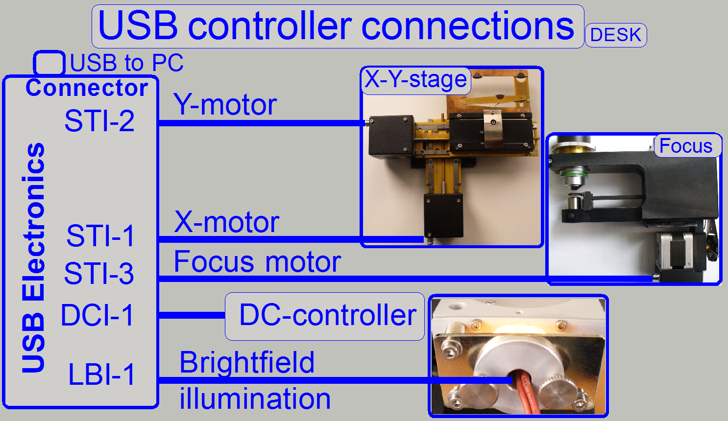
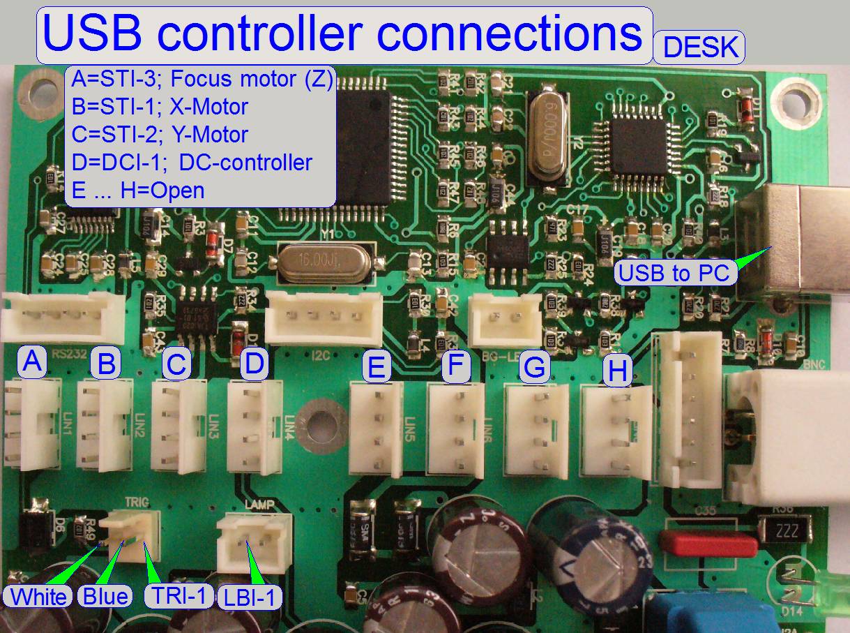
 The USB controller
receives the command for the units from the program SlideScanner.exe (the scan
program) or the SlideScannerService.exe (the
service program) via the USB control port of the PC and the USB cable.
The USB controller
receives the command for the units from the program SlideScanner.exe (the scan
program) or the SlideScannerService.exe (the
service program) via the USB control port of the PC and the USB cable.
All units that contain separate
electronics (stepper motors and DC-controller) are connected via a bus system.
To differentiate the units, connected to the USB controller, each stepper motor
electronics and the DC-controller as well has an address. Each data transfer
starts with the specified address for the unit and is listen by all units at
the same time, but only this unit receives the message, which internal address
and the message address is identical. The stepper electronics can receive
commands (number of steps to go and direction) and can send status information
(desired position reached and the status of the sensors Home1 and Home2). The status information will be send via the
USB cable to the software, hereby the address of the unit is used also.
 With this solution it is
possible to change the stepper motor cable with another stepper motor cable
(e.g. for fault detection) without any risk or functional restrictions. The
label of the cable for digital electronics has no reason in functionality; it
differentiates the cables from each other instead, because some cables are
shorter than others.
With this solution it is
possible to change the stepper motor cable with another stepper motor cable
(e.g. for fault detection) without any risk or functional restrictions. The
label of the cable for digital electronics has no reason in functionality; it
differentiates the cables from each other instead, because some cables are
shorter than others.
Important
The
construction of the controller powering on the board as well as the supplied
power does allow the drive of maximal 2 stepper motors at the same time!
· Please
take this into account, if you are working with the service program and the
batch test program module!
![]() Scanner cabling
and power supply
Scanner cabling
and power supply
USB- and DC-electronics box mounting
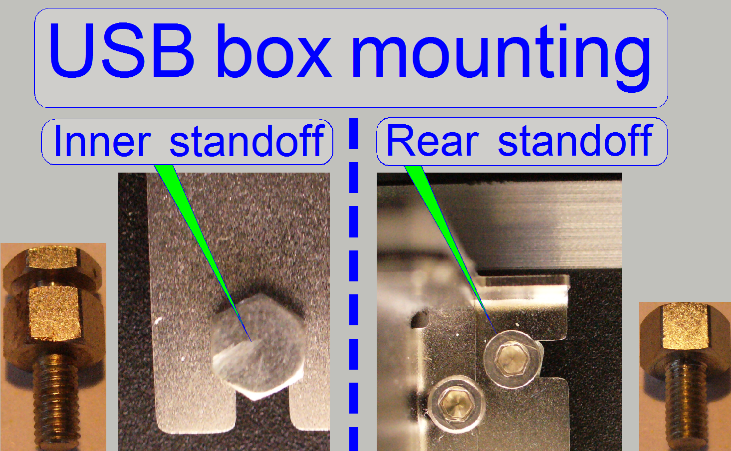 To allow an easy
exchange of the USB controller box, the inner (not reachable) standoffs have a
slot, in which the unit is shifted in; during the rear (reachable with the screw driver)
standoffs are fixing the USB- or DC-controller box by using a bolt.
To allow an easy
exchange of the USB controller box, the inner (not reachable) standoffs have a
slot, in which the unit is shifted in; during the rear (reachable with the screw driver)
standoffs are fixing the USB- or DC-controller box by using a bolt.
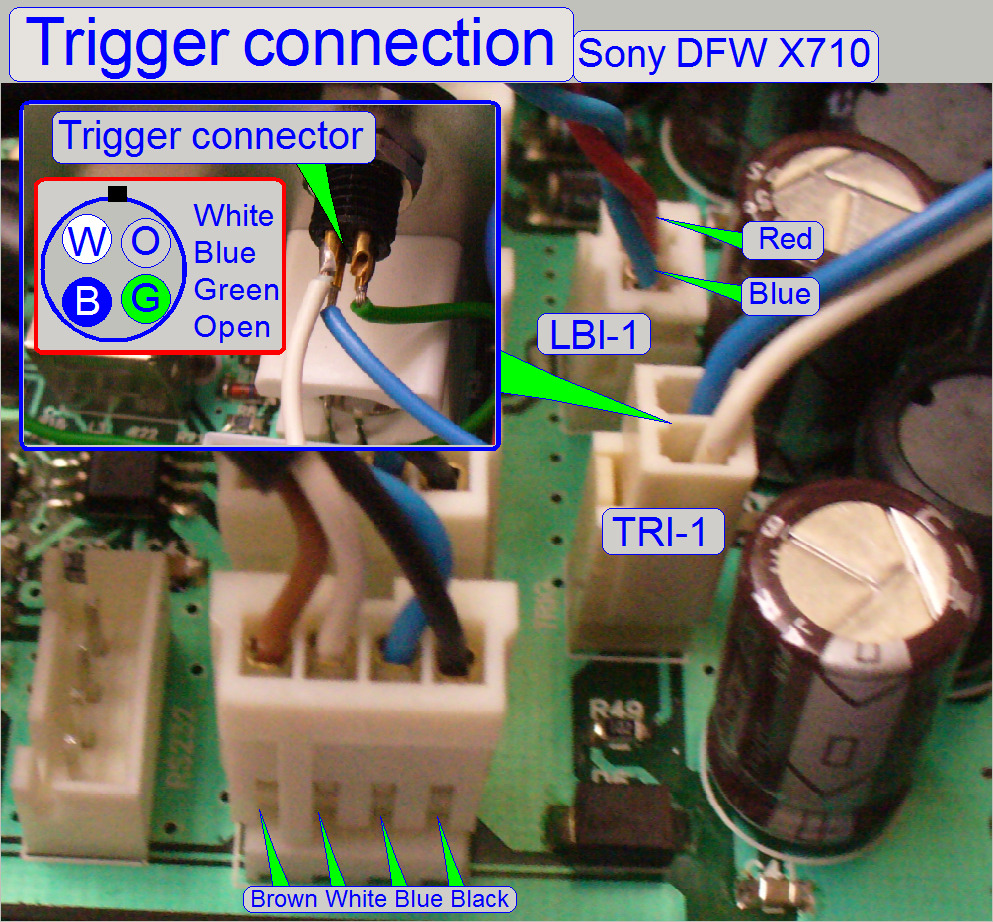
The trigger connector is used for the Sony camera
only and is identical for all the three scanner types.
If the camera is not recognized after changing the USB controller unit,
please check the correct cabling and the connections as shown on the right.

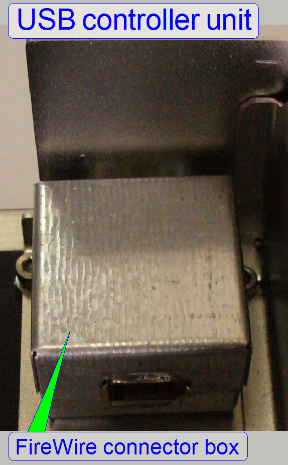 The FireWire
connector box contains a PCB on which two FireWire connectors are soldered.
There are no electronics components inside; the box realizes the connection of
the internal FireWire cable of the preview camera DFK 21F04 to the
external FireWire cable to the PC.
The FireWire
connector box contains a PCB on which two FireWire connectors are soldered.
There are no electronics components inside; the box realizes the connection of
the internal FireWire cable of the preview camera DFK 21F04 to the
external FireWire cable to the PC.
![]() “How to
check the preview camera”
“How to
check the preview camera”
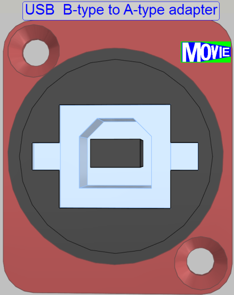
· If the scanner uses the preview camera VRmC-8+ PRO, the
FireWire connector box is replaced by an USB 2.0 port “B”- type connector.
|
Address of scanner unit |
||
|
Unit |
Address |
Type |
|
X-Y-Z
control |
00 |
C_P |
|
USB-controller |
01 |
All |
|
DC-controller |
02 |
P_S_M_D |
|
X-motor |
03 |
S_M_D |
|
Y-motor |
04 |
S_M_D |
|
Z-motor |
05 |
S_M_D |
|
Turret
unit |
06 |
S_M_P |
|
Tray
loader motor |
07 |
M_C |
|
Slide
loader motor |
08 |
M_C |
|
Objective
changer |
09 |
C_P_S_M |
|
Camera
changer |
10 |
P |
|
RGB
illumination |
11 |
C |
|
Reserve |
12 |
--- |
|
Immersion
liquid unit |
13 |
C |
|
Mechanical
shutter |
14 |
C |
|
Switch
board |
15 |
C_P |
|
Legend:
C=Confocal; P=P250; S=SCAN; M= |
||
The addresses are used by the
scan program and the service program to select the unit; these addresses are programmed
into the specified unit and can be changed via special software only. It is
important, that none of these addresses should exist twice inside of one
Pannoramic scanner, otherwise command or status mismatch occurs.
If data transfer is in progress, all addressable units listen to the
address of the data stream; if the address of the unit is identical with the
address of the data stream, the addressed unit is found and this receives the
information.
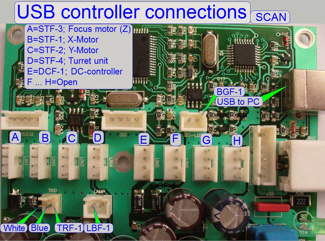
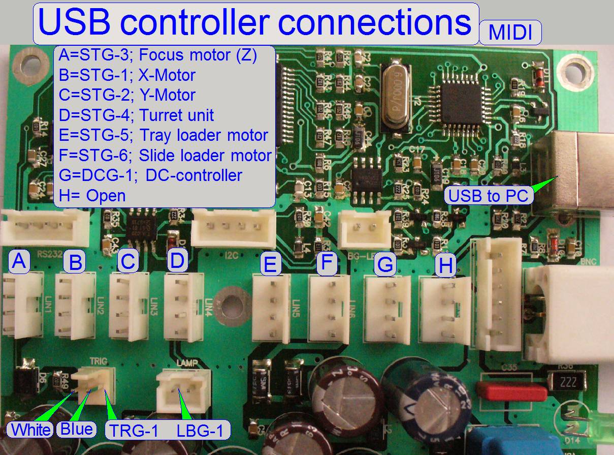
![]() “Cabling
of addressable units”
“Cabling
of addressable units”
Address assigning tool Serial.exe and start “Serial.exe”
 The EEPROM stores
the scanner specific parameters and these are collected in the files
MicroscopeConfiguration.ini and MicroscopeSettings.ini. To ensure an always
proper functioning of the scanner, the content of the EEPROM should be updated
after adjustments are done or units are exchanged and parameter values are
modified. The EEPROM is a part of the USB controllers PCB.
The EEPROM stores
the scanner specific parameters and these are collected in the files
MicroscopeConfiguration.ini and MicroscopeSettings.ini. To ensure an always
proper functioning of the scanner, the content of the EEPROM should be updated
after adjustments are done or units are exchanged and parameter values are
modified. The EEPROM is a part of the USB controllers PCB.
·
To update the content, the EEPROM should be cleared
with the service program.
·
If the scan software is started and the EEPROM is
empty, the content of the appropriate *.ini files will be written automatically
from the HDD into the EEPROM.
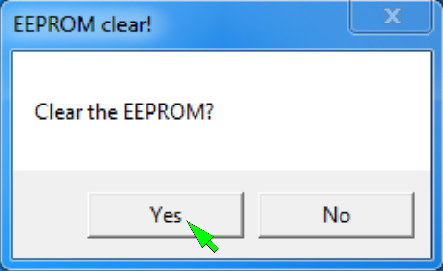
1. Start the program
“SlideScannerService.exe”, option “EEPROM clear”.
2. Answer the
dialogue with “Yes”; then the EEPROM is cleared.
3. Exit the service program
with “Exit”
4. Start the program
“SlideScanner.exe”; the *.ini-files will be automatically saved from the
appropriate HDD folder into the EEPROM during startup of the scan program, if
the EEPROM is empty.
![]() “Service program”; clear
EEPROM
“Service program”; clear
EEPROM
Compressed content of the EEPROM (P250, SCAN,
The compression of the EEPROM content is required since the software
version 1.16, because there are newly implemented parameters and the capacity
of the EEPROM is limited to be 2kB.
· By compressing the
content, memory space is won.
In systems, delivered with the version 1.16 the modified handling of the
EEPROM content will not be noticed by the user; the files
“MicroscopeConfiguration.ini” and “MicroscopeSettings.ini” staying on the HDD
in uncompressed form.
· If the EEPROM
content is written, the files “MicroscopeConfiguration.ini” and “MicroscopeSettings.ini”
will be compressed before these are stored in the EEPROM.
· If the EEPROM is
read, the content will be uncompressed before it is stored as file
“MicroscopeConfiguration.ini” and “MicroscopeSettings.ini” on the HDD.
If an upgrade is made (from the version 1.15 or lower to the version
1.16) the content in the EEPROM is uncompressed but the version 1.16 expects a
compressed content; therefore:
Before you are installing the software version 1.16
· Make sure; the
content of the files “MicroscopeConfiguration.ini” and “MicroscopeSettings.ini”
is the most recent content on the HDD.
· Save these files
to a save place
Install the software version 1.16
· Start the program
“SlideScanner.exe” first time.
· The compression of
the EEPROM content will be done automatically.
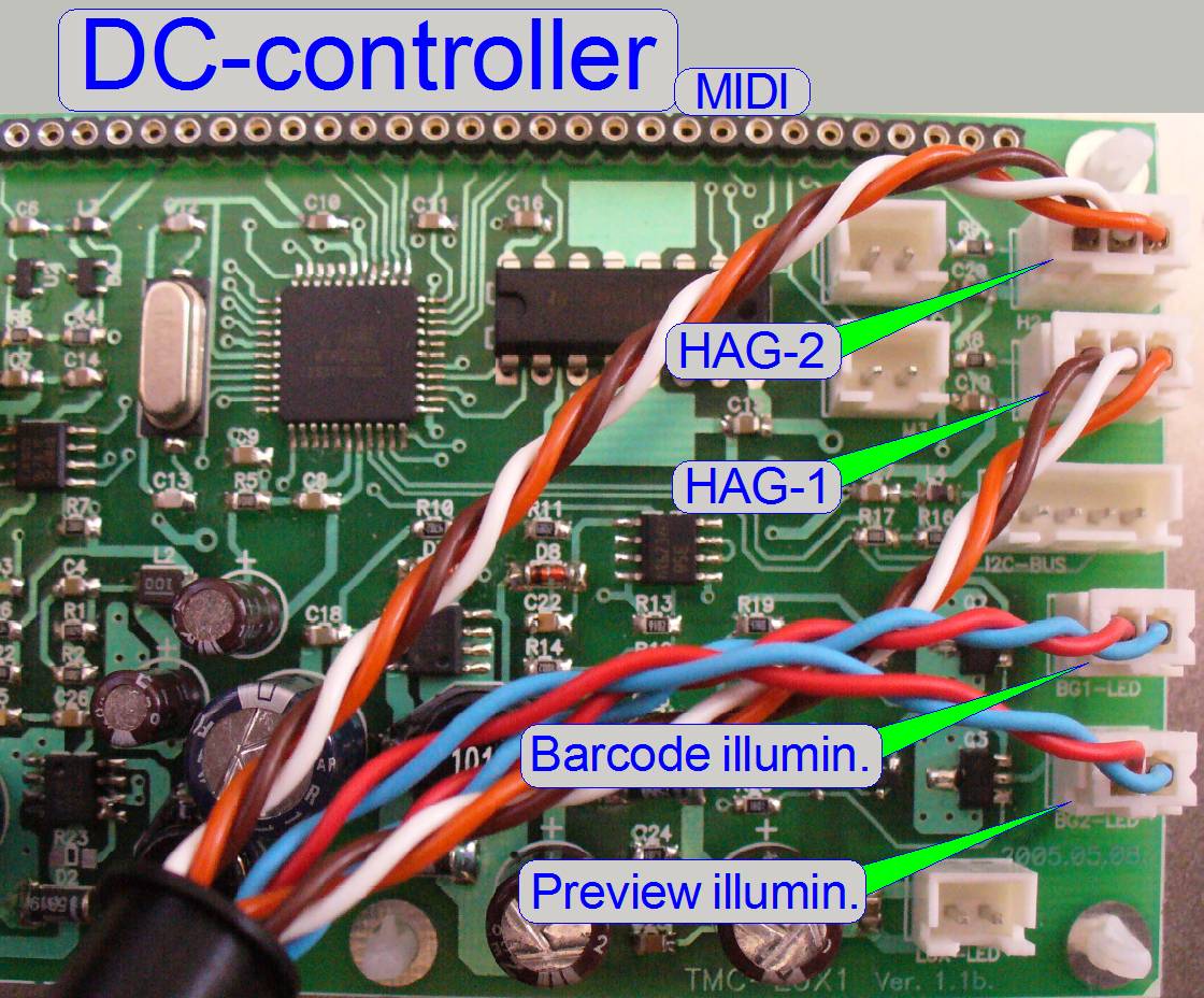
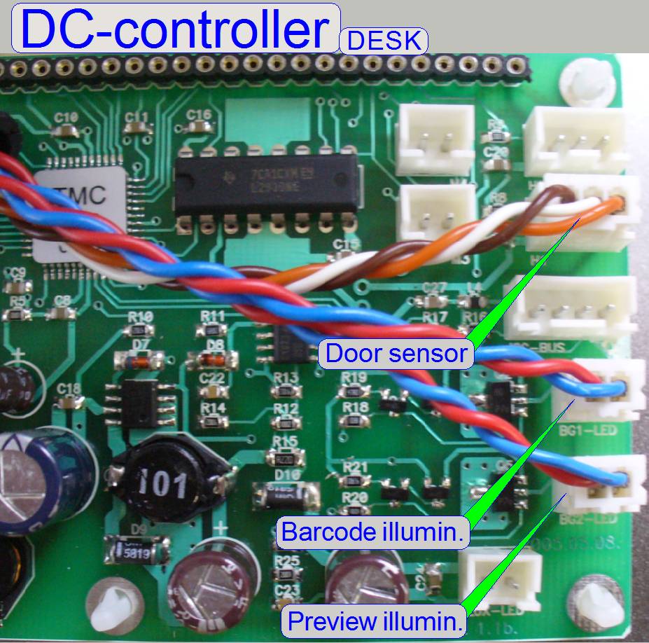
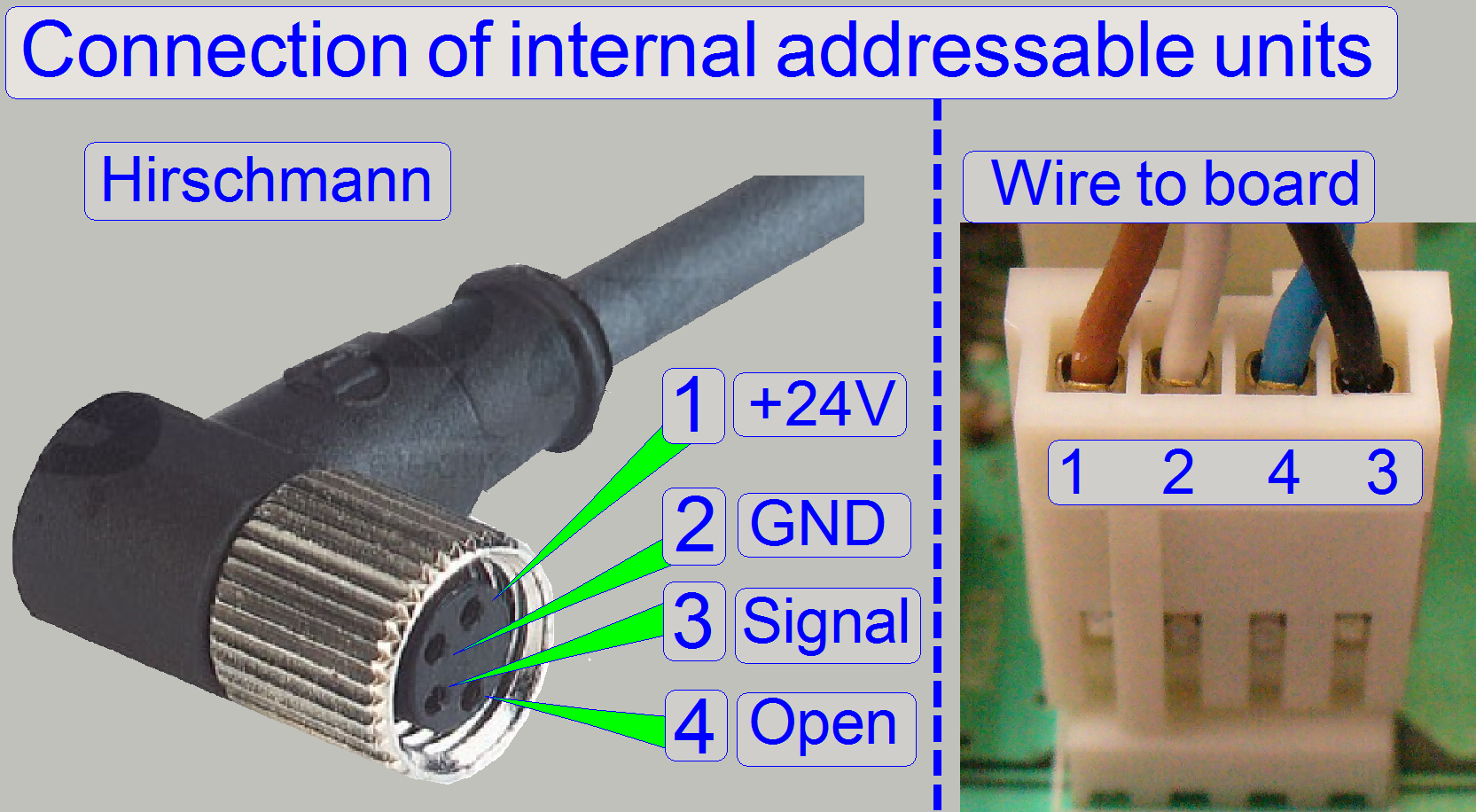 All the
addressable units are connected with the “Hirschmann” connector; the connection
is secured with a knurled nut. On the other end of the cable a “wire to board”
connector is used.
All the
addressable units are connected with the “Hirschmann” connector; the connection
is secured with a knurled nut. On the other end of the cable a “wire to board”
connector is used.

Attention
 Please switch off the power
supply before cable connecting or disconnecting.
Please switch off the power
supply before cable connecting or disconnecting.


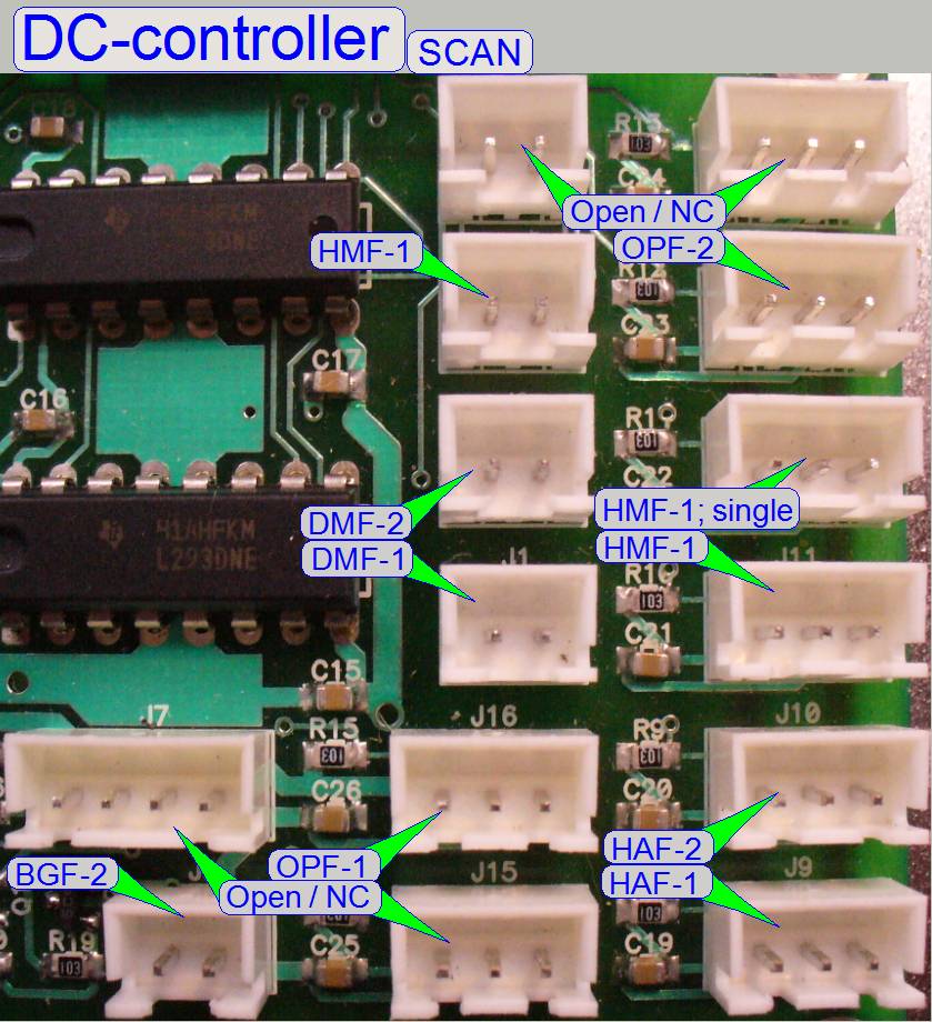
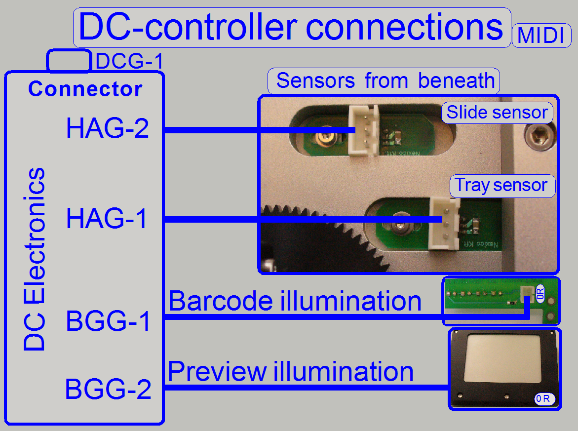
 The internal construction of
the DC-controllers is different to each other; the number of the connected
cables is limited or extended in according to the requirements.
The internal construction of
the DC-controllers is different to each other; the number of the connected
cables is limited or extended in according to the requirements.
The DC-controller switches the DC-motors and the preview illumination on
or off; collects the status information of the connected sensors and transmits
this to the USB-controller.
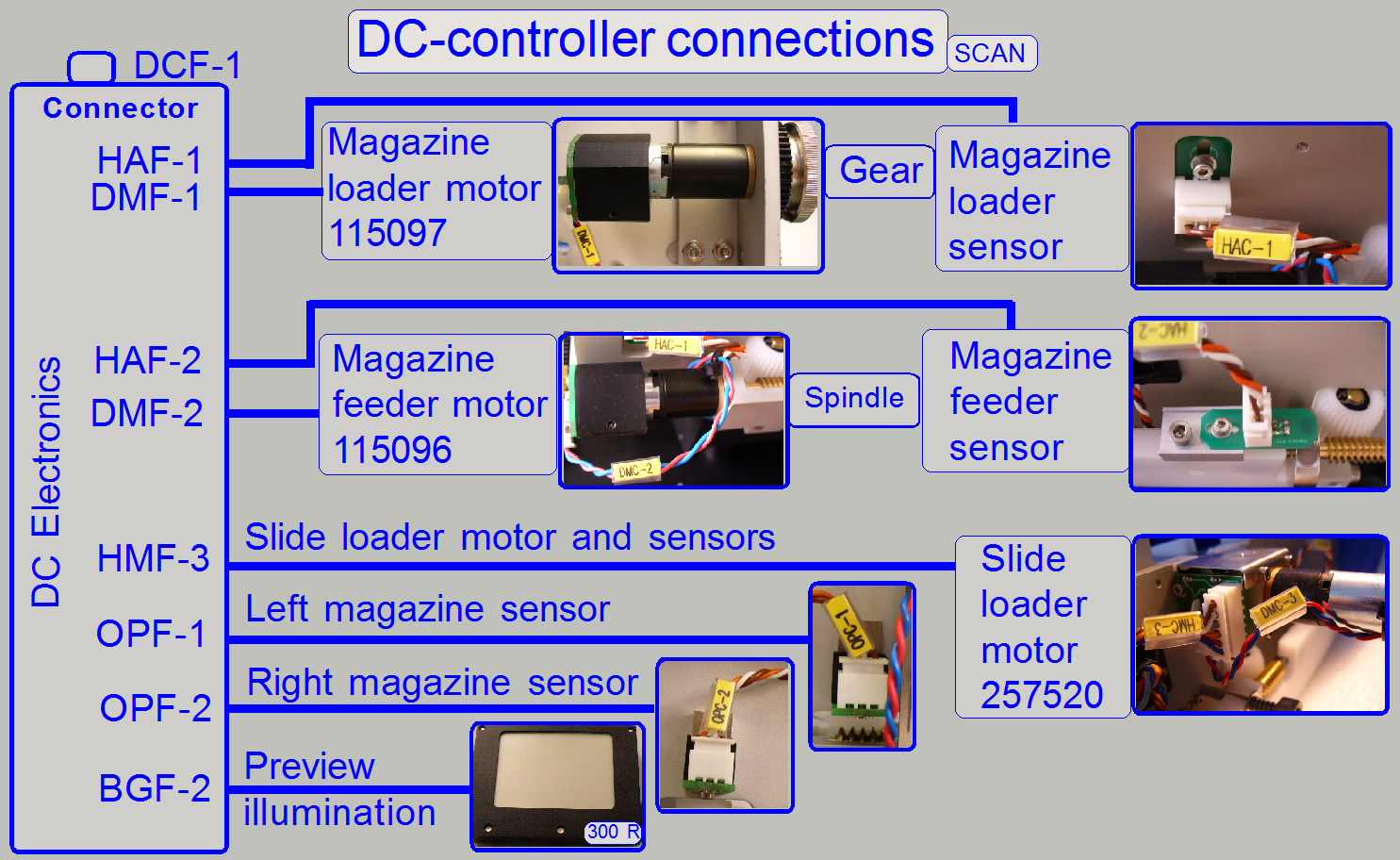

DC-motor implementation
The DC electronics box is
mounted onto the magazine unit from beneath. To prevent the DC-motors from
overload if hardware jamming occurs, all commands, starting the DC motors have
a time out (started by the scan software). Normally, the motor is stopped with
the sensor action before the time is run out. If the sensor action is missed
(jamming occurred) the time out event will switch off the motor.


About
basics, theory and principles please refer to:
http://www.solarbotics.net/library/pdflib/pdf/motorbas.pdf
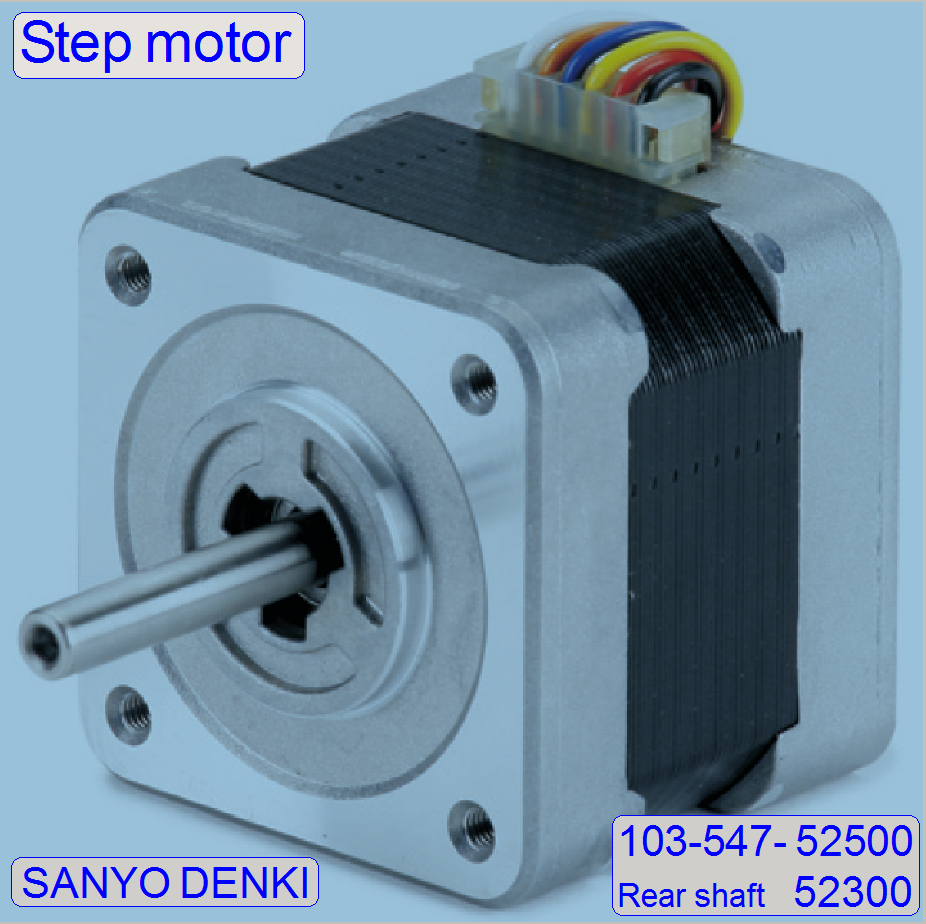
Stepper
motor basics (stored)
Drive circuit basics (stored)
Stepper motor and driver (stored)
External
recirculation diodes (stored)
Stepper motor
driving (stored)
Stepper motors 2011 (stored)
Electrical components
Background (preview) illumination
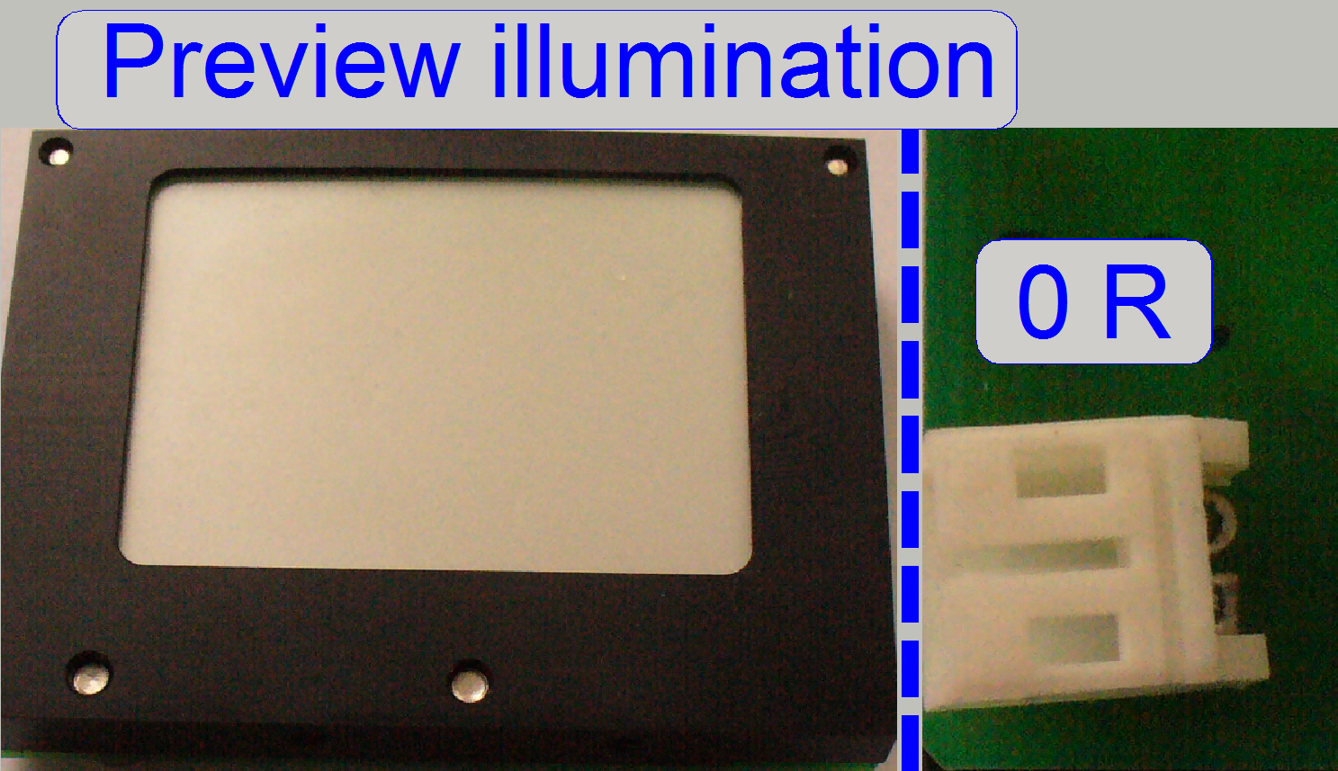 The preview
illumination consists of 6 LEDs and is used to illuminate the scan area part of
the slide and makes so the sample visible for the preview camera.
The preview
illumination consists of 6 LEDs and is used to illuminate the scan area part of
the slide and makes so the sample visible for the preview camera.
The preview illumination exists in two versions, a 0R and a 300R
version.
Because the output of the preview illumination for the SCAN is driven by
a voltage generator, the 300R version is used in the SCAN; in opposite to this,
the outputs of the MIDI and the DESK are driven by a current generator and
therefore the 0R version have to be used. The version of the preview
illumination is shown with 0R or 300R, near to the connector.
The intensity of the backlight can be adjusted in the range between 1
and 255 (maximum), 0 means the backlight is switched off (this should not be
used as a parameter value!). Until the software version 1.14, the parameter is
found in the file “MicroscopeConfiguration.ini” section
[PreviewAndBarcodeScanning].
[PreviewAndBarcodeScanning]
BackLightIntensity=120
The value is often found in the range between 100 and 150.

Important
If the 0R version is connected to the SCAN, the output BGF-2 may be
destroyed and the DC-controller needs to be replaced.
![]() LED Wikipedia
LED Wikipedia
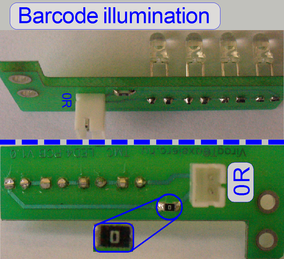 The barcode
illumination consists of four LEDs and is used to illuminate the barcode area of
the slide and makes so the barcode visible for the preview camera.
The barcode
illumination consists of four LEDs and is used to illuminate the barcode area of
the slide and makes so the barcode visible for the preview camera.
The barcode illumination exists in two versions, a 0R and a 510R
version. Because the output for the barcode illumination for the SCAN is driven
by a voltage generator, the 510R version is used in the SCAN; in opposite to
this, the outputs of the MIDI and the DESK are driven by a current generator
and therefore the 0R version have to be used. The version of the barcode
illumination is shown with 0R or 510R, near to the connector.
The intensity of the barcode illumination can be adjusted in the range
between 1 and 255(maximum), 0 means the barcode illumination is switched off
(this should not be used as a parameter value!).
Until the software version 1.14, the parameter is found in the file
“MicroscopeConfiguration.ini” section [PreviewAndBarcodeScanning].
AuxiliaryBackLightIntensity=255
The value is seldom modified.
Important
If the 0R version is connected to the SCAN, the output BGF-1 may be
destroyed and the USB-controller needs to be replaced.
To adjust the barcode illumination, please refer to “Preview_S_M_D” and
“Adjust the barcode
illumination”.

![]() LED Wikipedia
LED Wikipedia
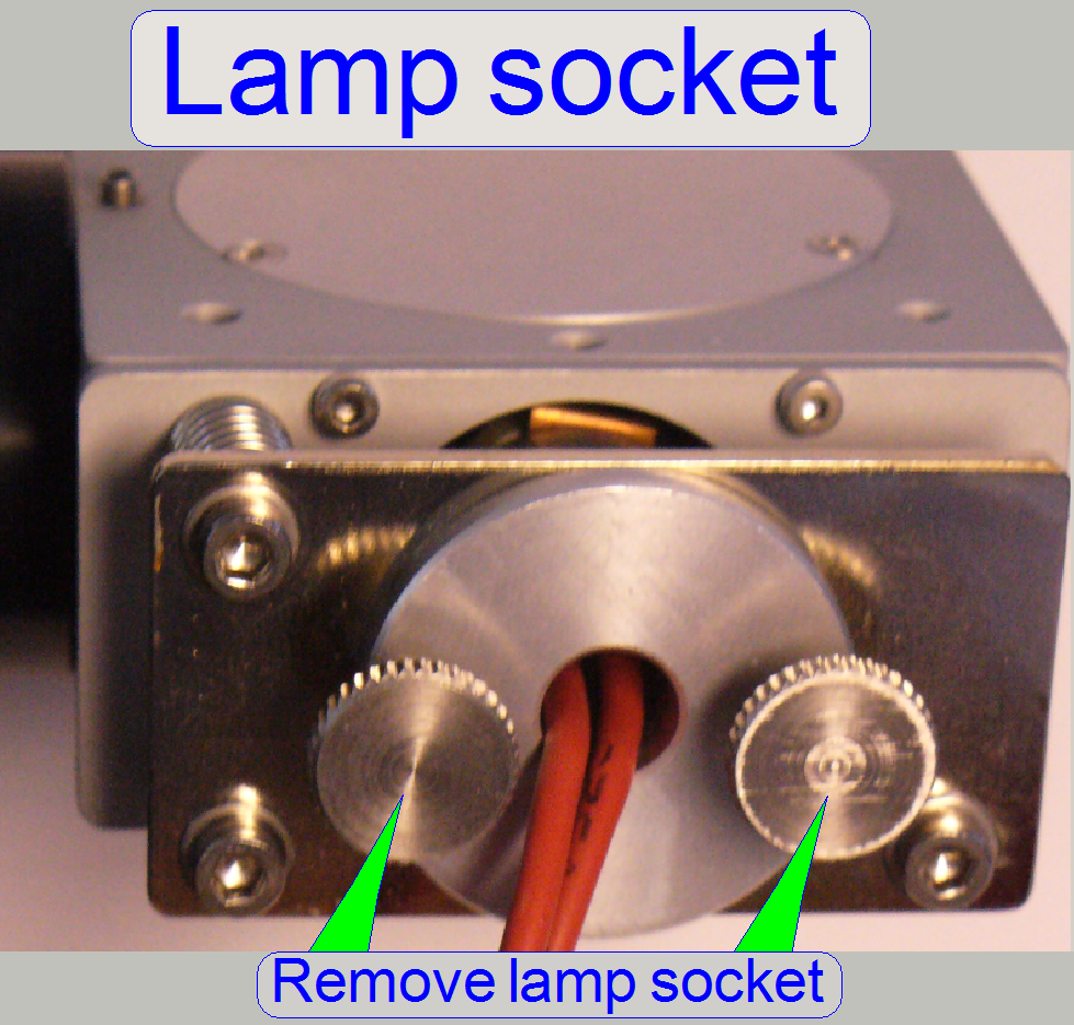 The brightfield
illumination is used to illuminate the field of view (FOV) for the scan camera
and the light source is a halogen lamp of 12V 5W.
The brightfield
illumination is used to illuminate the field of view (FOV) for the scan camera
and the light source is a halogen lamp of 12V 5W.
The type is: Osram Halostar Starlite 64405 S 12V – G4; 5W.
If the lamp was exchanged, the brightfield illumination should be
checked and adjusted if necessary; see “LUT-adjustment”.
Important
· Please do not use
a lamp with a power less than 5W! If the power of the halogen lamp is reduced,
the delivered amount of light will be also less and may be not enough to
illuminate the FOV; mainly if the tissue is a little bit thicker or the 40x
objective is used; the software will interrupt the scan process or will start
with “Illumination error” reports.
· Please do not use
a lamp with a power more than 5W! If the power of the halogen lamp is
increased, the control output of the brightfield scan illumination may be
destroyed!
Attention
Never touch the lamp glass with fingers! The lamp will burn out in a
half of an hour. If you have done so, clean the lamp glass entirely with
alcohol before switching on the lamp.
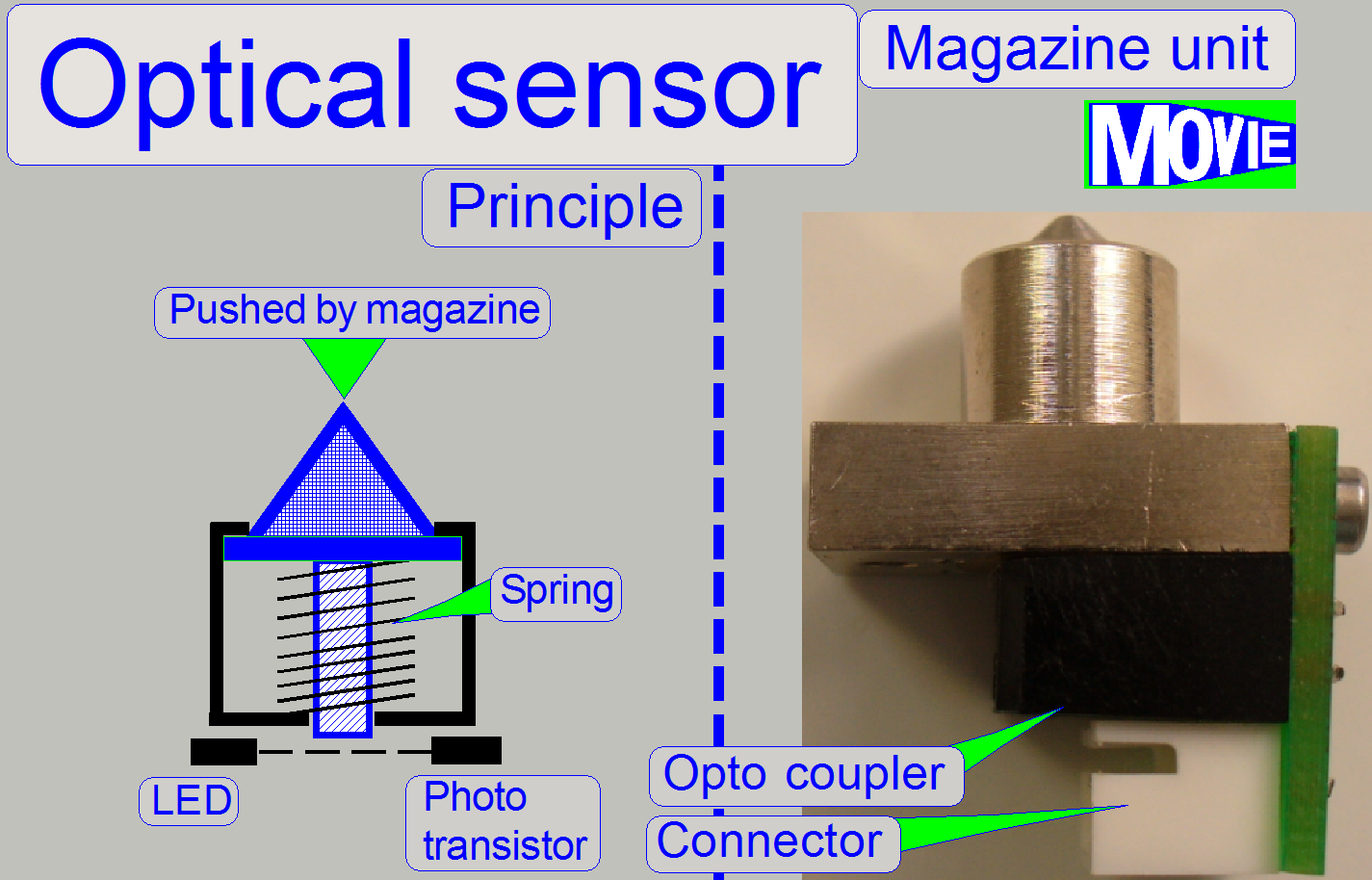 If the optical sensor OPF-1
and 2 (left and right magazine sensor) is pushed by the magazine, the light
path between LED and photo transistor will be interrupted by a pin. This action
is recognized by the software.
If the optical sensor OPF-1
and 2 (left and right magazine sensor) is pushed by the magazine, the light
path between LED and photo transistor will be interrupted by a pin. This action
is recognized by the software.
The sensors are situated on the magazine feeder channel bottom plate and
their positions are fixed.
· The sensors do not
need adjustment.
· The sensors should
be kept clean. Because the action path is very short, even small glass shards
or dust is able to prevent the sensor from correct switching.
![]() LED and photo
transistor Wikipedia
LED and photo
transistor Wikipedia
 Optical interrupter H22LOI Data sheet; stored
“Magazine Input Sensor” and “Magazine Output Sensor”
“How to exchange sensors
OPX_1_2”
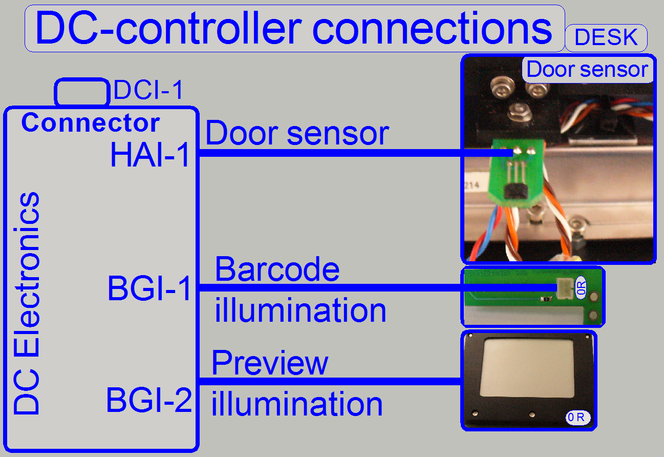
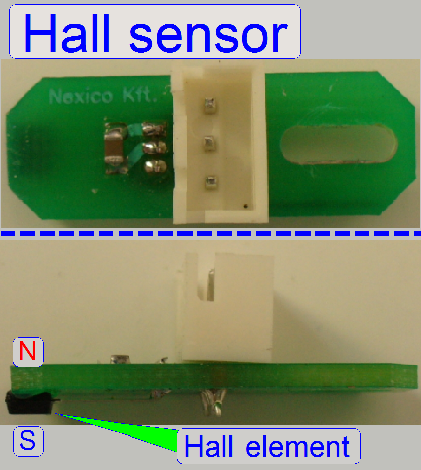 The “Magazine Loader
Sensor”, the “Magazine feeder
sensor”, the “Tray loader
sensor”, the “Slide
sensor” and the “Door sensor”
are realized with Hall elements.
The “Magazine Loader
Sensor”, the “Magazine feeder
sensor”, the “Tray loader
sensor”, the “Slide
sensor” and the “Door sensor”
are realized with Hall elements.
- If the south pole of a magnet is over the Hall element or the north
pole on the opposite side, the switch is closed and this state is
recognized by the software.
- If the polarity of the permanent magnet is inverted or a magnetic
field is not present, no action occurs.
- The sensors are so implemented, that the south pole of the
permanent magnet stays over the sensor surface if the action position is
reached.
· The sensor
position is adjustable.
· For adjustment procedures see
the appropriate chapters.
· The sensor does
not need maintenance.
![]() “Hall effect” Wikipedia
“Hall effect” Wikipedia
TLE4905L Data sheet; stored
USB-
and DC-controller cabling; summary
Cable labels
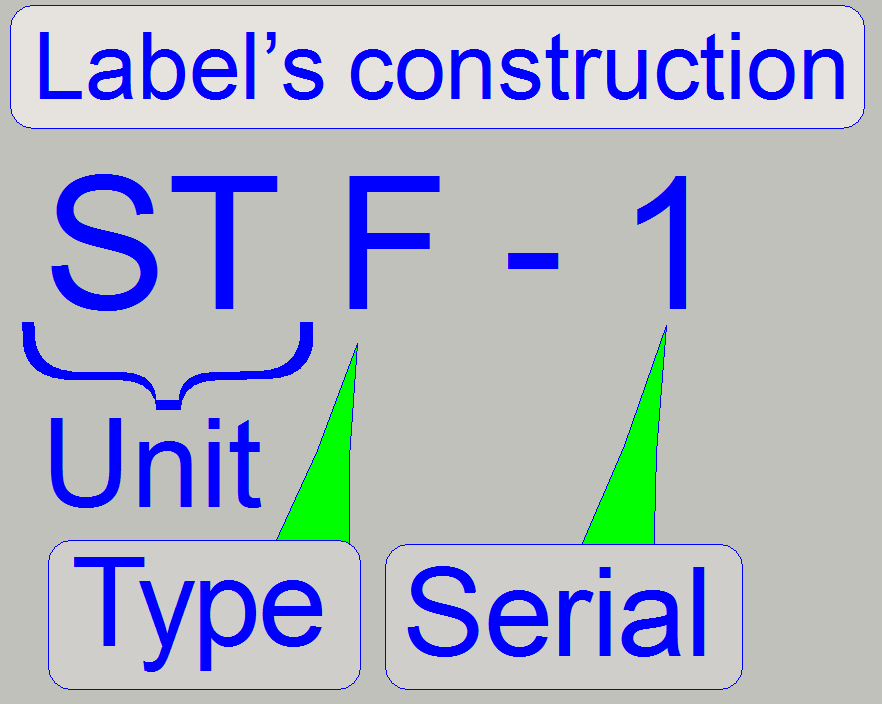 The first 2
letters of the cable label shows the dedicated unit, the 3rd
character defines the electronics version and the scanner type.
The first 2
letters of the cable label shows the dedicated unit, the 3rd
character defines the electronics version and the scanner type.
Unit
The first 2 letters are defining the unit to be connected.
Type
The type defines mainly the scanner and the electronics version while
delivering the scanner (since 2010). Previously delivered scanners (S_M_D) had
always the letter “C”
Serial
The number “Serial” defines the dedicated unit of the scanner. Often the
unit exists more times (like stepper motors) so the units from the same type
are distinguished. The serial number of stepper motor labels defines mainly
different cable lengths instead of different signals!
Example
The label “STF-
![]() “Cabling of addressable
units” and “Addresses”
“Cabling of addressable
units” and “Addresses”
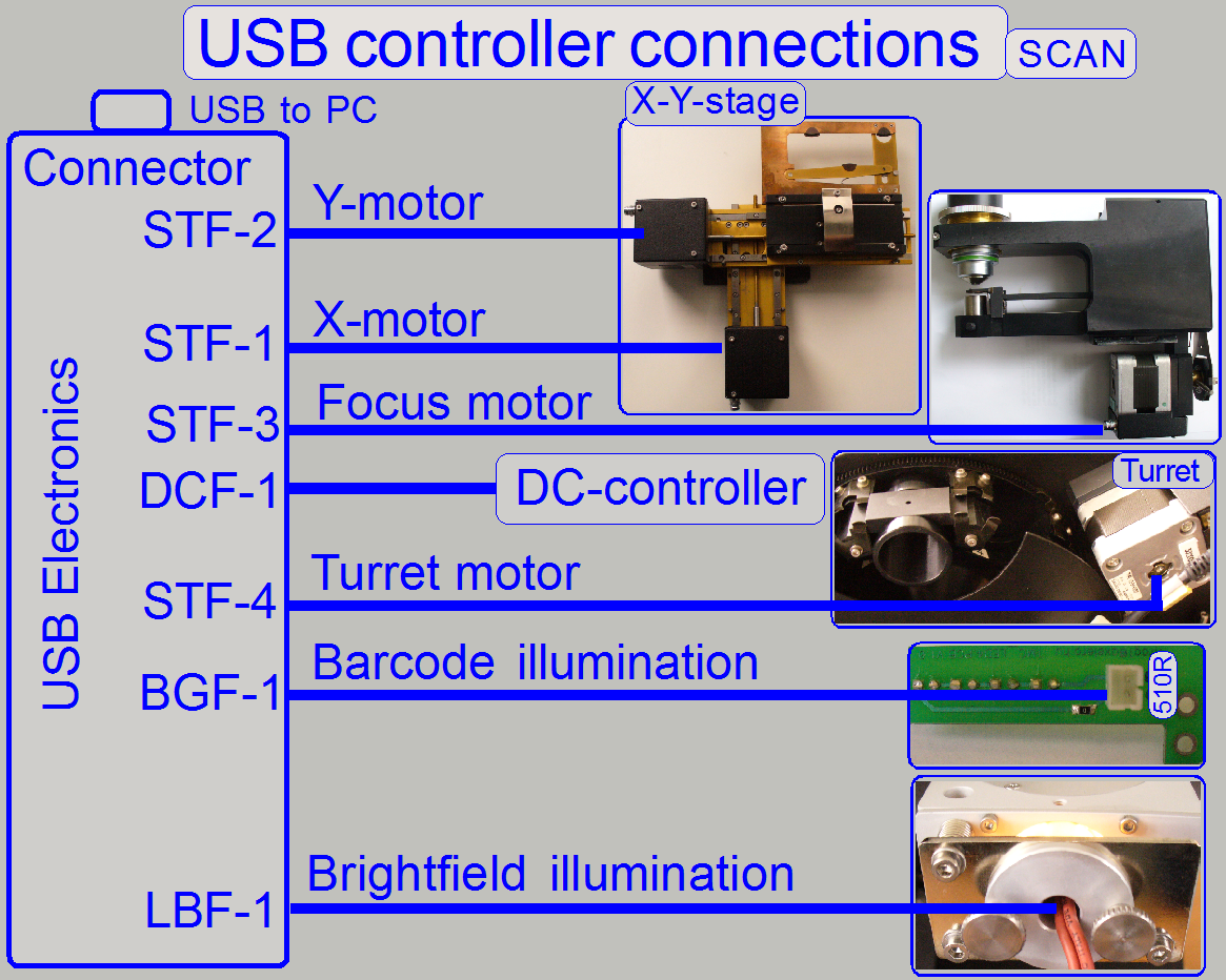
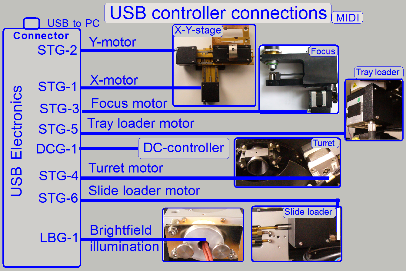
|
USB-controller
cabling; summary |
Cable
label |
|||
|
Unit |
Address |
DESK |
|
SCAN |
|
Reserve |
00 |
|
|
|
|
USB-controller |
01 |
USB
control cable from PC |
||
|
DC-controller |
02 |
DCI-1 |
DCG-1 |
DCF-1 |
|
X-motor |
03 |
STI-1 |
STG-1 |
STF-1 |
|
Y-motor |
04 |
STI-2 |
STG-2 |
STF-2 |
|
Z-motor;
focus |
05 |
STI-3 |
STG-3 |
STF-3 |
|
Turret
unit |
06 |
- |
STG-4 |
STF-4 |
|
Tray
loader motor |
07 |
- |
STG-5 |
- |
|
Slide
loader motor |
08 |
- |
STG-6 |
- |
|
Objective
changer |
09 |
- |
STG-3 |
|
|
Brightfield
illumination |
01x |
LBI-1 |
LBG-1 |
LBF-1 |
|
Barcode
illumination |
02x |
|
|
|
|
USB connector;
external |
- |
Preview camera cable to PC |
||
|
USB
connector; internal |
- |
FWI-1 |
FWG-1 |
FWF-1 |
|
DC-controller
cabling; summary |
Cable
label |
||
|
DESK |
|
SCAN |
|
|
USB-controller |
DCI-1 |
DCG-1 |
DCF-1 |
|
Door
switch (Sensor) |
HAI-1 |
- |
- |
|
Preview (background)
illumination |
BGI-2 |
BGG-2 |
BGF-2 |
|
Barcode
illumination |
BGI-1 |
BGG-1 |
- |
|
Slide
sensor |
- |
HAG-1 |
- |
|
Tray
sensor |
- |
HAG-2 |
- |
|
Left (input)
magazine sensor |
- |
- |
OPF-1 |
|
Right (output)
magazine sensor |
- |
- |
OPF-2 |
|
Magazine
loader sensor |
- |
- |
HAF-1 |
|
Magazine
feeder sensor |
- |
- |
HAF-2 |
|
Slide
loader cable |
- |
- |
HMF-1 |
|
Magazine
loader motor |
- |
- |
DMF-1 |
|
Magazine
feeder motor |
- |
- |
DMF-2 |
|
Slide
loader DC motor |
- |
- |
DMF-3 |