Batch test program
For technicians!
The description is based on “b-test.exe” version 1.13 until the software
version 1.14.
· Since the software
version 1.15, the “Batch Test” is implemented as a part of the service program.
· The mechanics and
addressable units of all 3DHISTECH scanners may be moved or tested!
Contents
Install the program “Batch test”
- This program is used to move units or parts of
the units of the scanners Pannoramic Confocal, 250, SCAN,
- The technician or the user is able to construct
its own sequence of commands to start and stop motor movements by the use
of events (sensor transition, sensor level, evaluated time or step number
done).
- The programmed actions can be arranged into a
cycle by using the do – while commands; the while command has a cycle
number.
- If the appropriate file
“MicroscopeConfiguration.ini” is assigned, the parameter value of the
specified parameter can be used also to define a number of steps to go; so
the correctness of the values can be checked.
- The program allows the connection of maximal 4
USB-controllers to one computer; the USB-controller may handle an entire
scanner or only connected units.
- The test sequence can be constructed in offline
mode also; hereby the units or the scanner must not be connected during
the development.
- Load and save operations of partly or fully
constructed batch file allow a quick check of connected units or the
construction of the batch file in intervals.
- With “merge” the batch module of an unit may be
used as a part of a more complex test sequence; existing batch files may
be assembled to a complex batch file.
Important
The construction of the USB controller
powering on the board does allow the drive of maximal 2 stepper motors at the
same time!
· Please do not move more than 2 stepper motor units of
the same USB controller at the same time!
·
To create a test batch file, programming knowledge is not
required; all the steps to create and run a batch file can be done by the use
of logic.
·
Deeper construction knowledge of Pannoramic scanners
and their units.
·
Installed Pannoramic scanner (or USB-controller with
connected units) to run the test sequences.
·
The installed version of the test program B-test.exe.
The program does not need a
special install procedure.
·  Create a folder of
the program “batch test” with version number on the drive C:\; e.g. C:\BatchTest_1_13
Create a folder of
the program “batch test” with version number on the drive C:\; e.g. C:\BatchTest_1_13
·
Copy the file “bTest.exe” and other
required files into this folder
·
Create a desktop icon
·
The installed scanner driver
·
Start the program
·
See also:
windows XP “Install the driver “ftdi2xx.inf”; win7
“Setup the USB
driver”
See also: Setup Service program;
Open ports
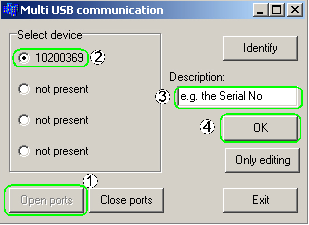 The program
searches for connected USB-controller units and lists the found serial number
of the USB-controller unit behind the appropriate radio button. The scanner or
the connected units are identified via the serial number of the connected
USB-controller unit.
The program
searches for connected USB-controller units and lists the found serial number
of the USB-controller unit behind the appropriate radio button. The scanner or
the connected units are identified via the serial number of the connected
USB-controller unit.
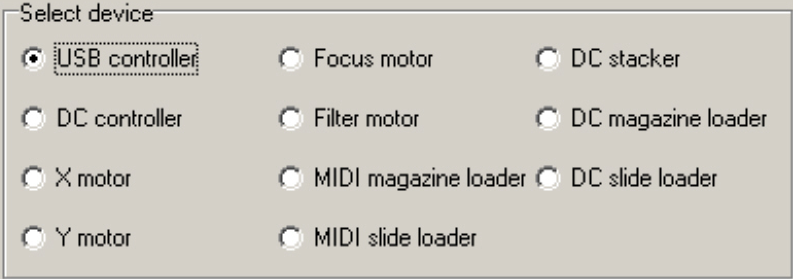
Select device
There can be maximal 4
USB-Controllers (scanners) connected; this allows the test or move of units of
the same type (or entire scanners) from the same computer; each unit of the
same type can be checked with its own, assigned batch file and the assigned
MicroscopeConfiguration.ini file.
The scanner (connected unit)
is identified by the serial number of the USB-controller; it can be found in
the near to the FireWire connector box or can be read out with the service
program “SlideScannerService.exe”.
The program will be started
for each connected USB-controller; so the program is running 4 times if four
units (USB-controllers or scanners) are connected.
Description
![]() For improved
differentiation of the units a text can be defined, this text (e.g. the serial
number of the scanner) is shown on the bottom of the screen. This option
becomes important if more then only one USB controller unit is connected.
For improved
differentiation of the units a text can be defined, this text (e.g. the serial
number of the scanner) is shown on the bottom of the screen. This option
becomes important if more then only one USB controller unit is connected.
Identify
Only
editing
This option can be used to construct
and edit batch sequences without connected scanner. To test and run the
batches, the appropriate scanner or unit(s) must be connected!
Close
port
Disconnect an USB-controller.
Exit
Leaf the program.
OK
After starting the program
“b-Test.exe” and pressing the button “Open port” (1) the program checks the
installed driver and lists the found serial numbers of the USB-controllers in
the field “Select device”. By click on the serial number (radio button) the
unit to be started is selected. Type a “Description” of the unit (if required)
and start the work screen by pressing “OK”.
 The program has
two batch file windows, the “Batch construction window” on the left and the
“Batch execution window” on the right. In the “Batch construction window” the
steps and the sequence of the commands are arranged and can be edited, during
the “Batch execution window” contain the batch for execution and load / save
operations. The batch file transfer between both windows is realized with the buttons
“Apply” and “Get”.
The program has
two batch file windows, the “Batch construction window” on the left and the
“Batch execution window” on the right. In the “Batch construction window” the
steps and the sequence of the commands are arranged and can be edited, during
the “Batch execution window” contain the batch for execution and load / save
operations. The batch file transfer between both windows is realized with the buttons
“Apply” and “Get”.

·
Load a batch
·
 Append batch
(Batch files can be merged)
Append batch
(Batch files can be merged)
·
Save batch
·
Save batch as ...
·
Load ini; Assign the appropriate file
“MicroscopeConfiguration.ini”
·
Run the batch
·
Pause / continue the batch
·
Stop the batch
·
Stop the batch in emergency events
Load
a batch program
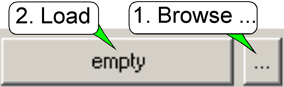 On the right side
of the “Batch execution window” a predefined batch file can be assigned to the
appropriate batch load button. By pressing the button “Browse”
On the right side
of the “Batch execution window” a predefined batch file can be assigned to the
appropriate batch load button. By pressing the button “Browse”![]() , the
batch file can be selected and its name will be assigned to the batch load
button; by pressing it, the assigned batch file is loaded into the “Batch
execution window”.
, the
batch file can be selected and its name will be assigned to the batch load
button; by pressing it, the assigned batch file is loaded into the “Batch
execution window”.
This way, nine different
batch files can be selected very quickly.
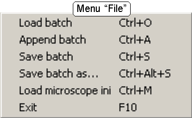
·
A batch file can also be loaded from the menu “File”.
Actions to define a test
sequence
·
Select and parameterize the step of the test sequence
in the section “Control”
·
Test; execute the defined step
·
Add the step to the “Batch construction window’s” list
·
Undo step or modification
·
Delete selected
·
Modify selected
·
Get from list (settings of the highlighted step are
load into the control field)
·
Apply Copy the
content of the “Batch construction window” to the “Batch execution window”.
·
Get Copy
the content of the “Batch execution window” to the “Batch construction window”.
 Apply
Apply
The content of the “Batch construction
window” is transferred to the “Batch execution window”; then the program can be
started. The content of the “Batch execution window” will be overwritten;
unsaved content is lost.
Get
The content of the “Batch
execution window” is transferred to the “Batch construction window”; then the
program can be edited. Unsaved content of the “Batch construction window” will
be lost; the content of the “Batch construction window” will be overwritten.
![]() The cursor highlights
the “New line” or the command to be edited by “The batch construction tools”.
The command to be inserted is always inserted before the cursor position.
The cursor highlights
the “New line” or the command to be edited by “The batch construction tools”.
The command to be inserted is always inserted before the cursor position.
![]() The “New line”
shows always the momentarily end of the program; further commands will be
always inserted before the “New line”, if the “New line” is the cursor position
also.
The “New line”
shows always the momentarily end of the program; further commands will be
always inserted before the “New line”, if the “New line” is the cursor position
also.
·
To highlight or select a command use the cursor
buttons “Up” / “Down”; or click on the command line.
 Each line is a
command also; each command is one line long and contains all the parameters and
values, defined in the field “Control”. By pressing the button “Add to list”
the defined command is transferred to the batch construction window and will be
inserted before the actual cursor position.
Each line is a
command also; each command is one line long and contains all the parameters and
values, defined in the field “Control”. By pressing the button “Add to list”
the defined command is transferred to the batch construction window and will be
inserted before the actual cursor position.
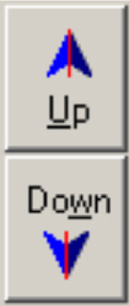
Up
The highlighted command is
moved one line (command) upward (in direction to the start of the program).
Down
The highlighted command is
moved one line (command) downward (in direction to the end of the program).
Add to
list
![]() The command, selected and parameterized in the
field “Control”, is inserted into the batch construction window; the actual
position is defined by the cursor position; see also above “The cursor”, “The
command” and “New Line”.
The command, selected and parameterized in the
field “Control”, is inserted into the batch construction window; the actual
position is defined by the cursor position; see also above “The cursor”, “The
command” and “New Line”.
Get
from list
Select a command by moving
the cursor on it or by clicking onto the desired command.
By click on “Get from list”
the values, defined by the selected command will set the field ”Control”; the
parameters and values of the control field are set by the command.
Undo
Delete
selected
Highlight the command to be
deleted, then press “Delete selected”. The command will be removed from the
sequence.
Modify
selected
·
Highlight the command to be modified then press “Get
from list”.
·
Modify the parameters and / or the values in the field
“Control”.
·
After all modifications are done, press “Modify
selected”.
The highlighted command is
modified by the new values and options, according to the actual settings in the
field “Control”.
Keyboard
commands
used in the “Batch
construction window”
* : Inverts the selection
Shift + cursor movement: highlights commands and parts of a command
Ctrl + c: Selected items are copied to the
clipboard (as usually in windows)
Ctrl + v: inserts the content of the clipboard
at the first highlighted position.
Ctrl + x: Copies the highlighted commands to the
clipboard and deletes them from the construction window.
The field “Control” contains
all the units, parameters, values and options to create and control the command
line for the unit to be tested or moved.
·
Unit specific options are only available in the lower
part of the field “Control”, if the appropriate unit is selected.
Selectable
units and commands
 The following
units, included in the scanner can be moved and checked. Because the check is
reduced to the unit itself, the scanner type is included in the specified unit
(e.g.
The following
units, included in the scanner can be moved and checked. Because the check is
reduced to the unit itself, the scanner type is included in the specified unit
(e.g.
·
All the unit names are command names also; so the use
of radio buttons allows selecting of only one command type at a time.
Batch control
Stop
test; the processing of the batch file ends here.
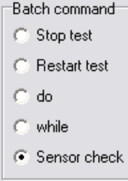 This is often the
last command of a test sequence.
This is often the
last command of a test sequence.
If the stop command is
missed, the test runs endless until the button “Stop” or “Emergency stop” is
pressed.
Restart test
The command sequence is started
again at the first command of the sequence.
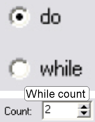
Do
The command “Do” is placed
before the first command to be executed in the cycle; it signalizes the start
of the loop and has no further parameters.
While
The command “While”
signalizes the end of the cycle (loop) and depending on the actual value of the
“While count”, the program execution is continued by the next command in
sequence after the command “While” or the program control executes the command
after the command “Do”.
·
The actual value of the “While count” is decreased by
1 before checking.
·
If “While
count”= 0: execute the next command in
sequence after “While”
·
If “While count”≠ 0: execute the command after “Do”
·
Do – while cycles can be nested
Sensor check
Sensor name: Select the sensor to be checked from
the list
State to check: High / Low
If the condition of more
sensors should be checked at the same time, the sensors and their active state
can be defined by using the mask.
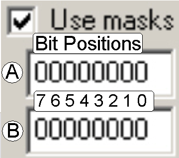 Use mask
Bit 7: Not used; always zero (0)
Bit 6: Not used; always zero (0)
Bit 5: Right magazine sensor
Bit 4: Left magazine sensor (SCAN; P250) / Tray sensor (
Bit 3: Slide loader inner sensor (SCAN; P250) / Slide sensor (
Bit 2: Slide loader outer sensor (SCAN; P250)
Bit 1: Magazine
feeder sensor (SCAN; P250)
Bit 0: Magazine loader sensor (SCAN; P250)
·
Select the sensors to be checked in the bit positions
in the line “A” of the mask by typing a “
·
Select (type in) the active level to be watched in the
bit positions in the line “B” of the mask; Low=0; High=1.
Example:
Wait
control
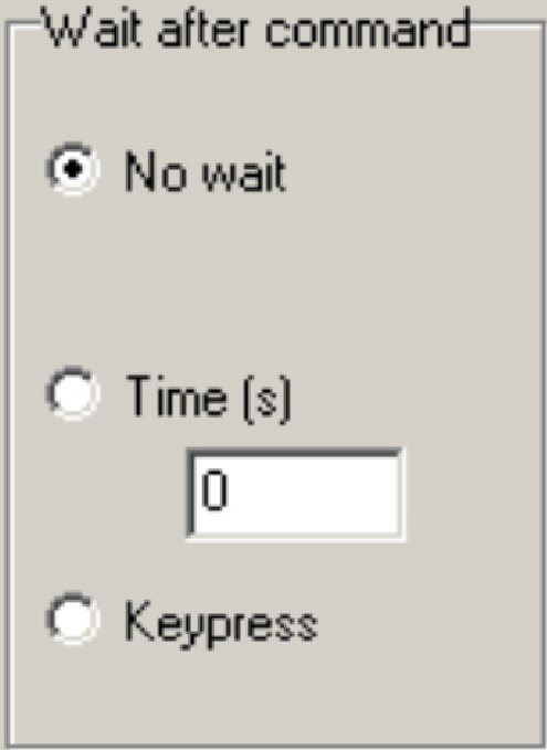
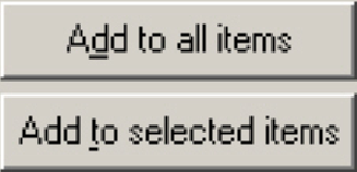 The wait control
offers the possibility to stop the command sequence after execution of the command
for check purposes; the execution of the command sequence can be interrupted
until the defined time is evaluated or a key was pressed. The selected option
is assigned to the actual command by pressing the button “Add to selected item”
or is added to all defined items by pressing the button “Add to all items”.
The wait control
offers the possibility to stop the command sequence after execution of the command
for check purposes; the execution of the command sequence can be interrupted
until the defined time is evaluated or a key was pressed. The selected option
is assigned to the actual command by pressing the button “Add to selected item”
or is added to all defined items by pressing the button “Add to all items”.
·
No Wait
The execution of the command
sequence is not interrupted; the next command in sequence will be executed
immediately.
·
Time (s)
The execution of the command
sequence is interrupted until the defined number of seconds is evaluated, then
the command sequence is continued with the next command in sequence. Is the
number of seconds zero (0), the result is the same as the option “No wait”
would be selected.
·
Key press
The execution of the command
sequence is interrupted until any key on the keyboard is pressed; then the next
command in sequence will be executed.
Cycle
control
 “Do”
“Do”
The command “Do” is placed before
the first command to be executed in the cycle; it signalizes the start of the
loop and has no further parameters.
“While”
The command “While”
signalizes the end of the cycle or loop and depending on the actual value of
the “While count”, the program execution is continued by the next command in
sequence after the command “While” or the program control executes the command
after the command “Do”.
·
The actual value of the “While count” is decreased by
1 before checking.
·
If “While
count”= 0: execute the next command in
sequence after “While”
·
If “While count”≠ 0: execute the command after “Do”
·
Do – while cycles can be nested in more levels
 Stop test
The command “Stop test” defines
the end of the batch program and is the last instruction of the program. If
“Stop test” is reached, no further commands are executed.
If the program is not
finished by the command “Stop test” (the command does not exist) the program
starts again with the first instruction on the top and is running continuously
until the button “Stop” is pressed or the power is switched off.
Test button
 If a unit is
selected and already parameterized, the settings of the field “Control” can be tested
on the connected unit by pressing the button “Test”.
If a unit is
selected and already parameterized, the settings of the field “Control” can be tested
on the connected unit by pressing the button “Test”.
It is very helpful if more
complicated actions like sensor edges, sensor levels or run time values must be
checked before the command is transferred to the batch construction window.
- The option can not be used in offline mode.
 Emergency
stop
Emergency
stop
In any cases, if
mechanical jamming occurs, all actions in progress are stopped.
· Press this button
if any action has to be stopped in emergency situations.
· The power switch on
the power supply can also be used to abort any movements.
Each unit, shown in the field
“Select device” is a command also; the command name is equal to the unit name.
The command name is the first
part of the command line; all the selected parameters and options are listed
after the command name, in the command line.
USB-Controller
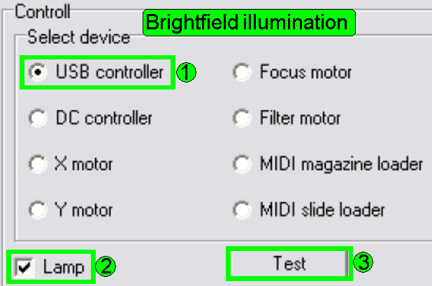 The USB controller
unit is used to switch on or off the brightfield illumination.
The USB controller
unit is used to switch on or off the brightfield illumination.
1.
Select the unit “USB controller (1)
2.
Check the checkbox “Lamp” (2)
3.
Click on test (3); result: the BF scan illumination is
switched on!
Switch off the brightfield
illumination
4.
Uncheck the checkbox “Lamp” (2)
5.
Click on test (3); result: the BF scan illumination is
switched off!
Implement the steps into the batch sequence
1.
Select the unit “USB controller (1)
2.
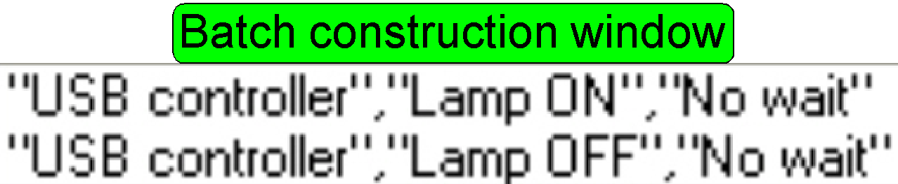 Check the checkbox
“Lamp” (2)
Check the checkbox
“Lamp” (2)
3.
![]() Click on “Add to
list”
Click on “Add to
list”
•
•
![]() •
•
4.
Select the unit “USB controller (1)
5.
Uncheck the checkbox “Lamp” (2)
6.
Click on “Add to list”. The result is shown in the batch construction
window.
DC-Controller
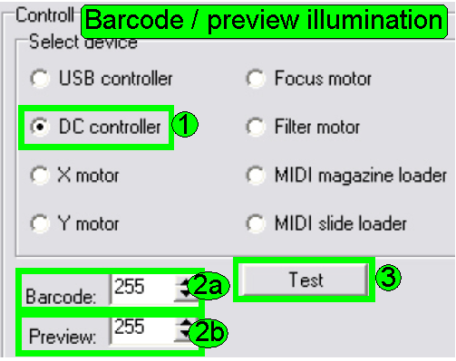 The DC-controller
is used to switch on or off the Backlight or the barcode illumination. If the
parameter value field is zero (0) the appropriate illumination is switched off;
if a value different from zero is defined, the illumination is switched on, and
the intensity depends on the value (max. value = 255).
The DC-controller
is used to switch on or off the Backlight or the barcode illumination. If the
parameter value field is zero (0) the appropriate illumination is switched off;
if a value different from zero is defined, the illumination is switched on, and
the intensity depends on the value (max. value = 255).
6.
Select the unit “DC controller” (1)
7.
Type into the numerical field a number between 1 and
255 as desired, 2a, 2b
8.
Click on test (3)
Switch off the barcode and
/or preview illumination
9.
Type into the numerical field zero (0), 2a and / or 2b
10.
Click on test (3)
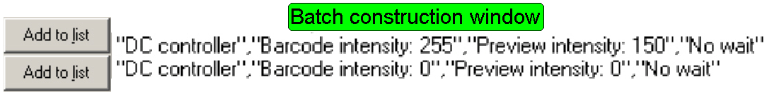
Implement the steps into the batch sequence
1.
Select the unit “DC controller” (1)
2.
Type into the numerical field a number between 1 and
255 as desired, 2a=255, 2b = 150
3.
Click on “Add to list”. The result is shown in the batch construction window.
•
 •
•
•
4.
Select the unit “DC controller” (1)
5.
Type into the numerical field zero (0), 2a and / or 2b
6.
Click on “Add to list”. The result is shown in the batch construction window.
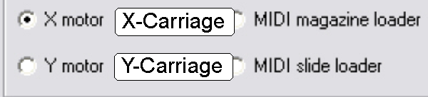 By selecting the
unit “X motor” the entire X-carriage can be moved and checked.
By selecting the
unit “X motor” the entire X-carriage can be moved and checked.
In the lower part of the
field “Control” the options and parameters for the command are shown.
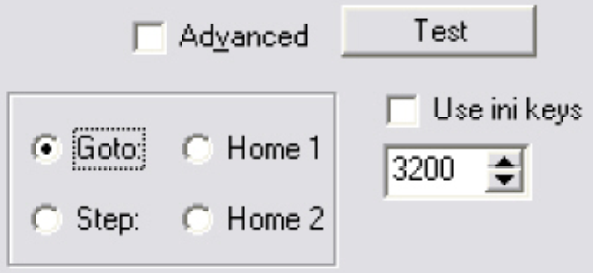 Goto
Goto
The value in the numeric
field defines the absolute motor position, counted from Home 1,2. The number of
steps to go from the actual position to reach the absolute position, defined by
the numerical value is calculated by the program.
·
Negative motor positions starting with a minus (-)
sign.
Step
Go the number of steps in
positive or negative direction, counted from the actual position.
·
Negative values starting with a minus (-) sign.
Home 1
Set the stepper motor to Home 1; see also
Home 2
Set the stepper motor to Home 2; see also
Use ini keys
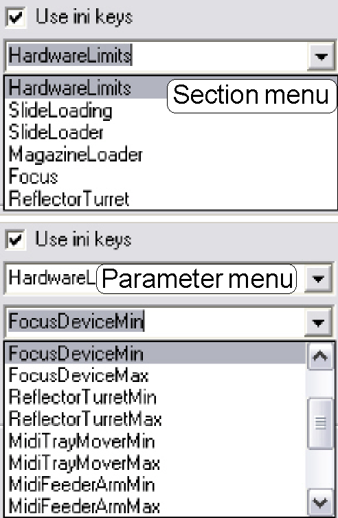
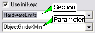 If the checkbox “Use
ini keys” is checked, two pull down menus are available, the first menu
contains the relevant sections of the assigned file
“MicroscopeConfiguration.ini”; the second menu contains all the parameter names
of the selected section. This way, the value, assigned to any parameter name of
the selected section can be used to move the motor.
If the checkbox “Use
ini keys” is checked, two pull down menus are available, the first menu
contains the relevant sections of the assigned file
“MicroscopeConfiguration.ini”; the second menu contains all the parameter names
of the selected section. This way, the value, assigned to any parameter name of
the selected section can be used to move the motor.
Important
The program does not check
the correctness of the used parameter name; the sense and correctness of the
used parameter has to be checked by the batch file constructor!
The parameter value is
handled as motor position to be reached; it is the absolute position of the
motor in motor steps, counted from Home 1,2; see also above
“Goto”.
Information about the usable
parameter names and values can be found in the chapters
o
“The scan area”
o
“Magazine unit and slide
loading”
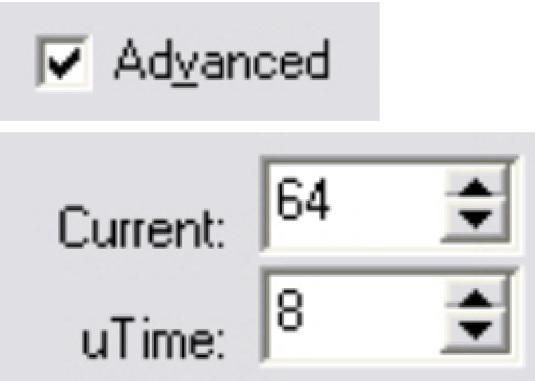
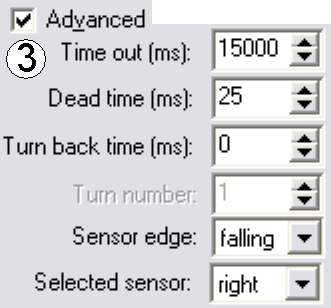
Advanced
If “Advanced” is checked,
further parameters are available.
 Because the motors
are driven in micro step mode the useable values are limited.
Because the motors
are driven in micro step mode the useable values are limited.
Current
Reasonable values are found in the range from 32
-127. This value influences the current thru the stepper motor coil and so the
torque of the stepper motor. By modification of this value the optimum between
torque, noise and vibration of the motor will be affected. If the value is too
high the accuracy of the micro step is modified (1 step ≠ 1 μm), if the value is too low, lost steps can
be produced or the rotor will not rotate.
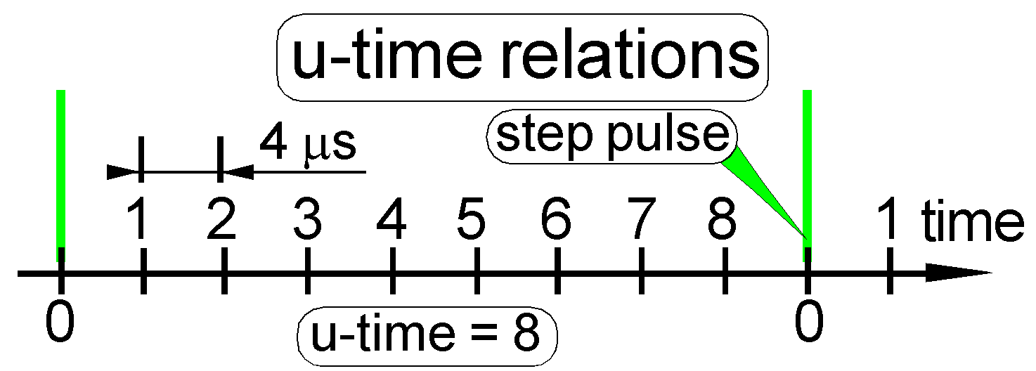 The u-time
· The “u-time” parameter means the “time of one micro
step” (“u” means “μ”) and is used to define the time
evaluated between the execution of 2 micro steps of the rotor.
· The u-time is used as a factor and defines the pause
time between two steps that following each other if the rotor rotates with the
full speed. This factor affects both, the full speed and the torque of the
rotor as well; the torque and the speed are nonlinear reciprocal to each other.
· The u-time is defined for
each motor separate in the software, depending on the driven mechanics; e.g.
the turret motor has to handle higher load then the focus motor.
· This value defines the possible full speed of the
stepper motor.
The value of the u-time may be varied between 8 and 64; lower values
define higher speed with reduced torque, higher values define higher torque
with lower speed; noise and vibration may be affected also.
The calculation
of the u-time
Time between two step pulses = (u-time + 1) x 4 μs
Usable values are:
8 ≤ u-time ≤ 64
A value, lower then u-time=8
should not be used, because missed steps can occur or the mechanical drive will
not start. If the value of the u-time will be increased, the motor speed
reduces and the torque increases.
Further, stepper motor
relevant information can be found in the chapter “USB
and DC-controlling” and “The stepper motor
implementation”
Don’t wait until motor stops
 The batch execution
command control will stop, until the command is executed. Only, if the status
“desired position reached” is receipt from the motor, the command execution
control goes to the next command in sequence.
The batch execution
command control will stop, until the command is executed. Only, if the status
“desired position reached” is receipt from the motor, the command execution
control goes to the next command in sequence.
If the checkbox is
checked
The command execution control of the program
issues the “Number of steps to go” to the motor and executes the next command
in the batch sequence immediately without waiting for the status answer. The status of “desired position reached” will
be checked before the next command is issued to this motor.
Remark
In question of power load, not more than 2
stepper motors should run at the same time!
Y-carriage
For parameters and their
explanation please refer to the chapter above “X-carriage”
Information about the usable
parameter names and values can be found in the chapters
o
“Magazine unit and slide
loading”
Focus and shutter unit
For the command explanation and
their parameters please refer to the chapter above
o
“X-carriage”
Information about the usable
parameter names and values of the focus unit can be found in the chapter
o
“The focus unit”
FL reflector turret unit (filter wheel)
For the command explanation
and the parameters please refer to the chapter above
o
“X-carriage”
Information about the usable
parameter names and values of the filter wheel drive can be found in the
chapter
o
“The FL
reflector turret unit”
For the command explanation
and the parameters please refer to the chapter above
o
“X-carriage”
Information about the usable
parameter names and values of the tray loader can be found in the chapter
o
“The tray- and slide loading”
For the command explanation
and the parameters please refer to the chapter above
o
“X-carriage”
Information about the usable
parameter names and values of the slide loader can be found in the chapter
o
“The tray- and slide
loading”
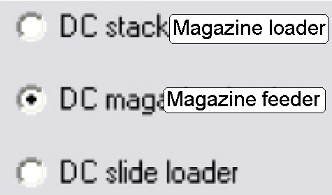 DC-Stacker (Magazine loader)
DC-Magazine loader (Magazine feeder)
DC-Slide loader
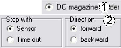 Example program (Magazine feeder)
·
The magazine is manually inserted into the feeder channel
from the left side.
·
Move the magazine in the feeder channel forward until
the right magazine sensor is released;
·
Move the magazine backward in the feeder channel until
the left magazine sensor is released.
·
The movement should be done continuously (endless).
The
steps:
1.
 Select the
magazine feeder unit (1)
Select the
magazine feeder unit (1)
2.
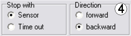
Set “stop with sensor” and “forward” (2)
3.
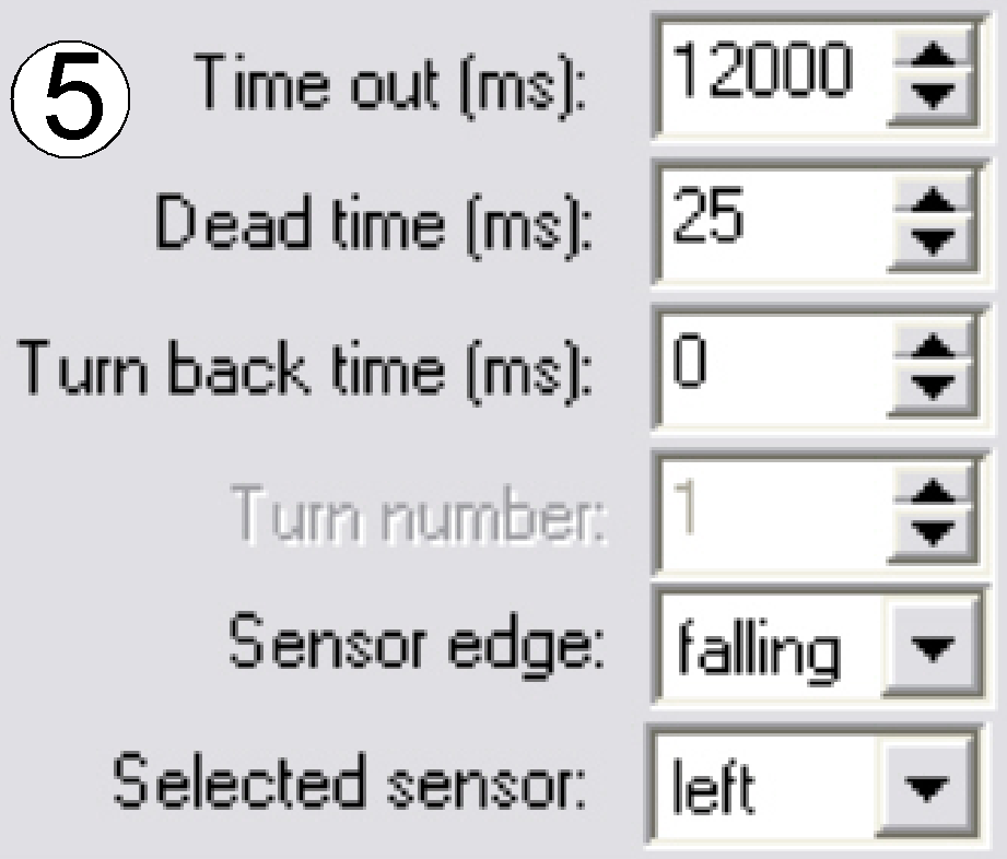
In the menu “Advanced” set the parameters as shown
(3).
4.
Press ‘Add to list”
5.
Set “stop with sensor” and “backward” (4)
6.
In the menu “Advanced” set the parameters as shown
(5).
7.
Press ‘Add to list”
8.
Press ‘Apply”
9.
Insert the magazine into the magazine channel from the
left side.
10. Press the button
“Start”.
11. The program will
run continuously until the program is stopped with the stop button or the power
will be switched off.
12. Save the file with
the menu “File”.