Fluorescent exciting
For
technicians and sales managers!
In FL exciting the scanner uses fluorescence to generate
an image of FOV. The specimen is illuminated with light of a specific wavelength which is absorbed by the fluorophore causing it to emit light (a different color than the
absorbed light). The illumination light is separated from the much weaker
emitted fluorescence using a spectral emission filter. In this manner, the
distribution of a single fluorophore is imaged at a time. In order to make a
successful setup may be important to consider the spectral property of the
light source. It is also important to know the characteristics of the
fluorophores used to label the specimen, because the filter cubes must be
chosen to match the spectral excitation and emission characteristics of
them. Mainly components for staining and
preparing of the specimen are discussed as well as principles of exciting and
imaging of stained specimens.
The following description handles knowledge and principles
to understand the components and construction of the Reflector Turret Unit
(RTU) and components for fluorescent scan processes.
Because there are very much staining materials
(fluorophores), many light filters and light sources, also for special purposes
available, it is important to know which combinations are possible and
constructive or should be avoided or are impossible.
Contents
Characteristics
of camera sensor
Principles
of exciting and imaging

In Medicine or The Life
Sciences, it is often important to differentiate cell compartment like cell
membrane, nucleus or pathological statuses like normal or tumor tissue. To do
so, fluorescence staining is used. The fluorescent dye can be a small molecule,
or protein. To dye the specimen, specific organelle markers or antibodies
labelled with fluorophore is used. These dyes are bonding to a special
biochemical structure and serves as a marker of this structure. A wide range of
fluorophores is available to label these markers and antibodies, by using
different fluorophores (stains) for desired structures and staining the tissue,
a stained specimen is created. Often the specimen is stained with 3,4 or 5
fluorophores, seldom more.
![]() Epi-Fluorescence Microscopy LINK (stored)
Epi-Fluorescence Microscopy LINK (stored)
Fluorescence and
Fluorescence Applications (stored)
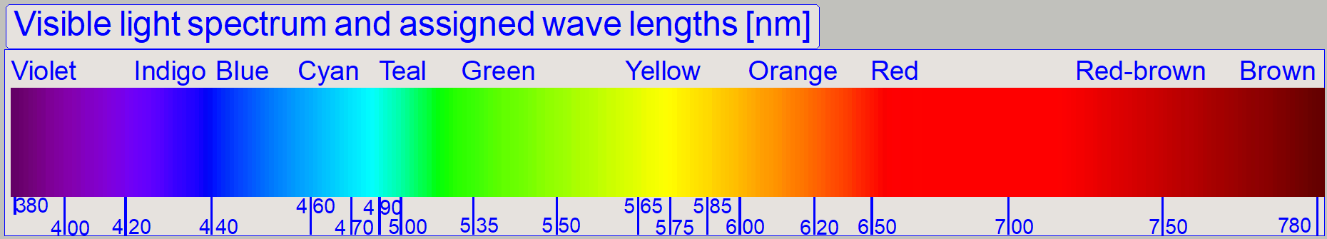 Principally it is commonly known that the visible spectrum
of light is found in the range from about 380nm to 780nm. The name of the color
people learned in his childhood, therefore there are often differences in
naming colors, mainly if the clear color crosses over to the next color, e.g.
blue to green and so on. To make the color more precise, mainly in technical
aspects, we can use the frequency or the wavelength of the color.
Principally it is commonly known that the visible spectrum
of light is found in the range from about 380nm to 780nm. The name of the color
people learned in his childhood, therefore there are often differences in
naming colors, mainly if the clear color crosses over to the next color, e.g.
blue to green and so on. To make the color more precise, mainly in technical
aspects, we can use the frequency or the wavelength of the color.
Fluorescent scan components are using the wavelength
of the light. Because people are working with color names and technique is
working with wavelengths, a comparison of both is sometimes helpful.
![]() Wavelength
to Colour Relationship interactive
spectrum of visible light
Wavelength
to Colour Relationship interactive
spectrum of visible light
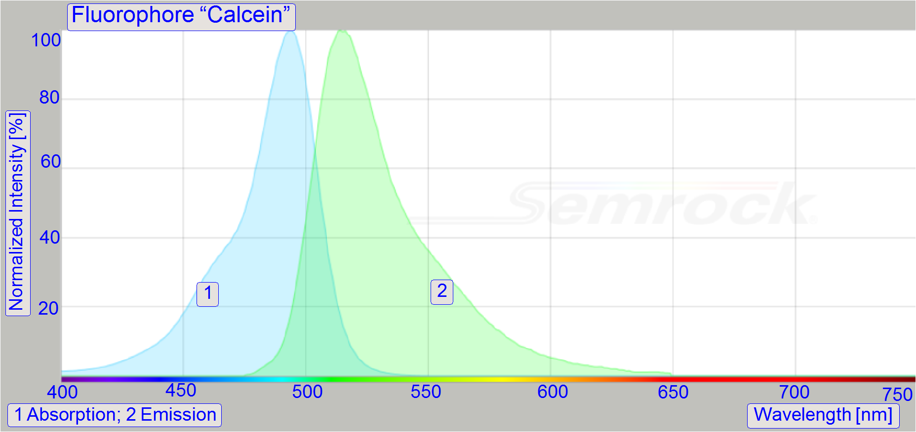
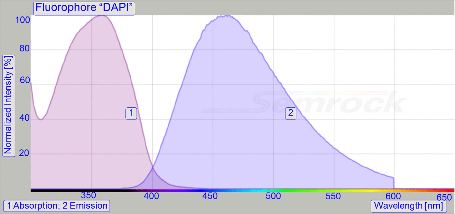
 A fluorophore (or
fluorochrome) is a fluorescent chemical compound that can emit
light upon light excitation. Fluorophores typically contain several combined
aromatic groups, planar or cyclic molecules with several π bonds. The fluorescence is
the emission of light by a fluorophore that has absorbed light.
The emitted light has a longer wavelength,
and therefore lower energy, than the absorbed (exciting) light. The fluorophore
ceases to glow immediately when the light source stops. Wavelengths of maximum
excitation and emission are the typical terms used to refer to a fluorophore,
but the whole spectrum may be important to consider. Fluorophores are generally
used to stain tissues, cells, or materials in a variety of analytical methods, i.e. fluorescent imaging and spectroscopy. See Definitions
A fluorophore (or
fluorochrome) is a fluorescent chemical compound that can emit
light upon light excitation. Fluorophores typically contain several combined
aromatic groups, planar or cyclic molecules with several π bonds. The fluorescence is
the emission of light by a fluorophore that has absorbed light.
The emitted light has a longer wavelength,
and therefore lower energy, than the absorbed (exciting) light. The fluorophore
ceases to glow immediately when the light source stops. Wavelengths of maximum
excitation and emission are the typical terms used to refer to a fluorophore,
but the whole spectrum may be important to consider. Fluorophores are generally
used to stain tissues, cells, or materials in a variety of analytical methods, i.e. fluorescent imaging and spectroscopy. See Definitions
- A fluorophore is excited by absorbing high energy from a light
source of appropriate wavelength and emits low energy and low intensity
longer wavelength.
Important
True for all fluorophores: High energy, exciting wavelength is always
shorter than the low energy emitted wavelength; the difference is more 10nm.
|
Fluorophores, selection |
||
|
Fluorophore |
Excit |
Emiss |
|
358 |
463 |
|
|
Hoechst
34580 |
392 |
440 |
|
401 |
421 |
|
|
404 |
455 |
|
|
498 |
526 |
|
|
489 |
511 |
|
|
495 |
520 |
|
|
494 |
514 |
|
|
556 |
572 |
|
|
558 |
575 |
|
|
554 |
587 |
|
|
553 |
573 |
|
|
653 |
668 |
|
|
644 |
670 |
|
|
651 |
673 |
|
|
650 |
673 |
|
|
Wavelength in [nm] |
||
![]() Fluorophore Wikipedia;
Fluorophore Wikipedia;
Fluorescence Excitation and Emission
Fundamentals (stored)
Fluorophore table (stored)
DAPI Wikipedia
Dyes IDT
Spectra
Database University of Arizona
Fluorophore Selection Thermo
Fisher
Photobleaching
of the specimen
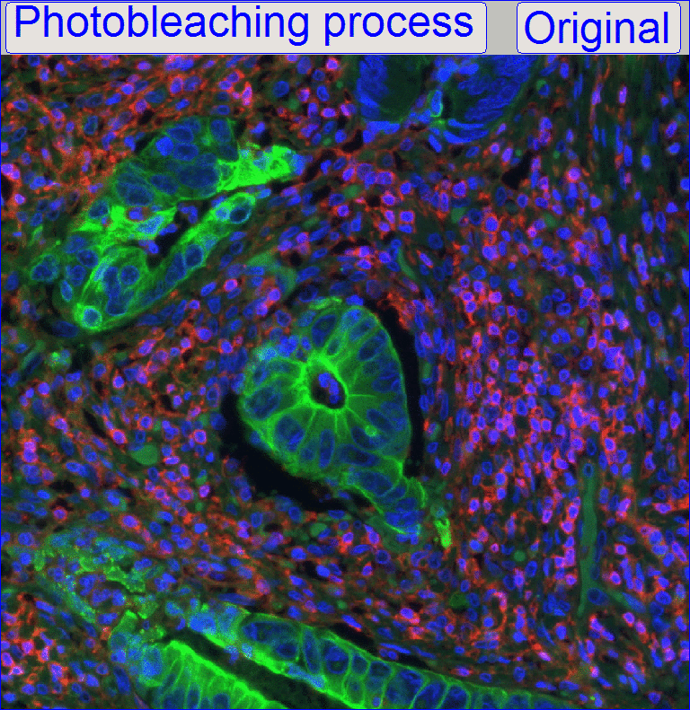 In fluorescent
microscopy, the phenomenon of photobleaching (sometimes termed fading) occurs
when a fluorophore loses the ability to fluoresce permanently. Photobleaching
is provoked by non-specific reactions between the fluorophore and surrounding
molecules caused by the excitation light. Some
fluorophores bleach quickly after emitting only a few photons, while others
that are more robust can bear thousands or millions of cycles before bleaching.
Loss of activity caused by photobleaching can be controlled by reducing
the intensity or time of light exposure.
In fluorescent
microscopy, the phenomenon of photobleaching (sometimes termed fading) occurs
when a fluorophore loses the ability to fluoresce permanently. Photobleaching
is provoked by non-specific reactions between the fluorophore and surrounding
molecules caused by the excitation light. Some
fluorophores bleach quickly after emitting only a few photons, while others
that are more robust can bear thousands or millions of cycles before bleaching.
Loss of activity caused by photobleaching can be controlled by reducing
the intensity or time of light exposure.
·
The scan quality of photobleached specimen
is (drastically) reduced.
·
Fully bleached specimen is unusable in fluorescent scan procedures.
Responsibilities for bleaching
·
Light and heat sensitivity. Because fluorophores are sensitive to light
and heat, the specimen should be stored in a dark and cool surrounding (e.g. in
a box of the refrigerator).
·
Sunlight sensitivity. Never expose the stained
specimens to sunlight, this would increase bleaching drastically.
·
Exposure time sensitivity. Minimize the exposure time of the
Excitation light by switching it off after the image is taken or remove the
filter block from the exiting path.
·
Use the live view for adjustments as short as
possible.
·
Exciting power sensitivity. Decrease the exciting power and time as
possible.
![]() Photo bleaching (Wikipedia)
Photo bleaching (Wikipedia)
Photo bleaching (Florida
State University)
Photo bleaching (stored)
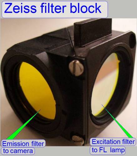
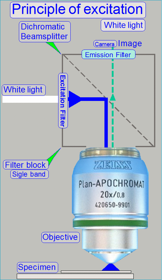
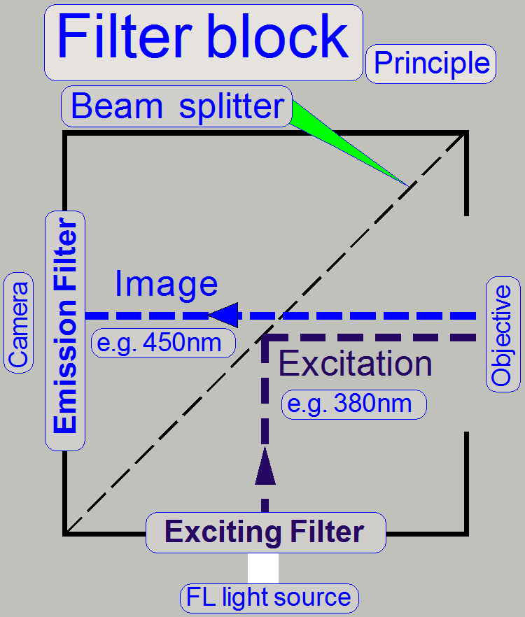 Optical filters are
used to selectively transmit light in a range of wavelengths while
reflecting wavelengths outside the defined range. They can usually pass long
wavelengths only (longpass), short wavelengths only (shortpass), or a band of
wavelengths, blocking both longer and shorter wavelengths (bandpass). Dichroic
mirrors (beamsplitters) are specialized
filters which are designed to efficiently reflect excitation wavelengths and
pass emission wavelengths. The filter suitable for the exciting wavelength and
the filter fitted for the emitting wavelength as well as the dichroic mirror
are mounted in a filter block.
Optical filters are
used to selectively transmit light in a range of wavelengths while
reflecting wavelengths outside the defined range. They can usually pass long
wavelengths only (longpass), short wavelengths only (shortpass), or a band of
wavelengths, blocking both longer and shorter wavelengths (bandpass). Dichroic
mirrors (beamsplitters) are specialized
filters which are designed to efficiently reflect excitation wavelengths and
pass emission wavelengths. The filter suitable for the exciting wavelength and
the filter fitted for the emitting wavelength as well as the dichroic mirror
are mounted in a filter block.
The filters
of the filter block are combined for a special stain. In other words, every
stain (fluorophore) has its optimal exciting wave length and the appropriate
optimal emitting wavelength. For these wavelengths the filter block components
are combined. This means also, that every stain has its own filter block, but
one filter block may serve several analogous fluorophores.
The filter
block filters the exiting light, arriving from the excitation light source, and
the dichroic mirror directs it via the objective to the stained specimen and
excites there the fluorophore. The excited fluorophore of the specimen’s FOV
emits light in a longer wave length. The emitted light is collected by the
objective and passes through the dichroic mirror and the emission filter to the
camera.
Single band
filters will be filtering one exciting wave length (range) and will be
filtering the adequate emission wavelength (range).
Advantage
The exciting wavelength can be filtered from a white
light source.
Disadvantage
If another exciting wavelength is required, the filter
set has to be changed physically and this is time consuming in relation to the
scan procedure.
Exciting and emission wavelength
On filters and other components principally the center
wavelength and the guaranteed bandwidth is defined.
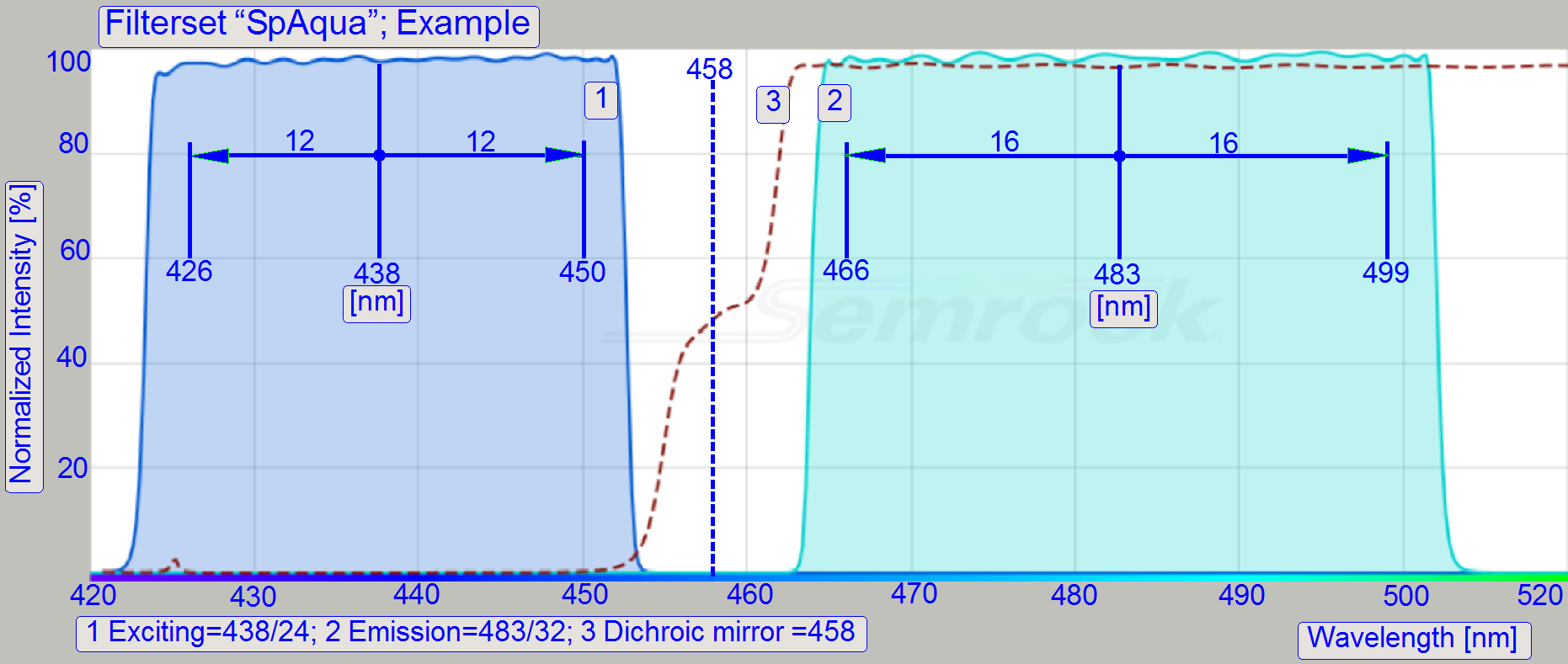 The
bandwidth is divided by two and one half number is subtracted from, while the
other half is added to the center wavelength.
The
bandwidth is divided by two and one half number is subtracted from, while the
other half is added to the center wavelength.
- The value
438/24 (SpAqua) means, the center wavelength is 438nm and the bandwidth is
24nm.
The following link may help you to find possible as well
as impossible combinations.
 “Matching
Fluorescent Probes with Nikon Fluorescence Filter Blocks”; interactive
“Matching
Fluorescent Probes with Nikon Fluorescence Filter Blocks”; interactive
Because the filterblock has to be changed if the
exciting wavelength will be changed, and this procedure is time consuming
related to the scan process, multiband filters are created.
 Multiband
Multiband filters combining more excitation and
adequate emission wavelengths inside of one filter set.
In Pannoramic scanner types mainly quad band filters
are used as multiband filters.
Advantage
The filter block has to be changed only, if an
exciting wavelength is required which is not included in the quad band set.
This way the scan procedure is done much faster
because the filter block has to be changed less often.
Disadvantage
The exciting wavelength cannot be filtered from a
white light source. Every exciting light wavelength has to be created
separately and will be switched on or off as required.
This construction makes the exciting light source more
expensive.
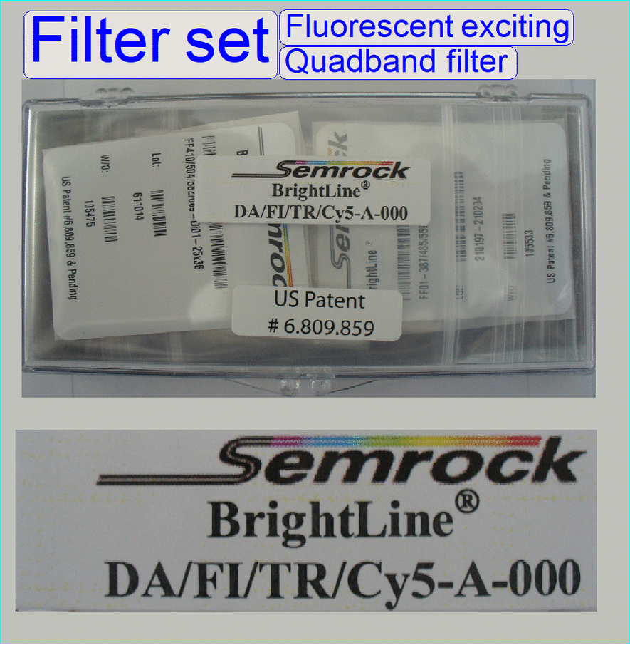
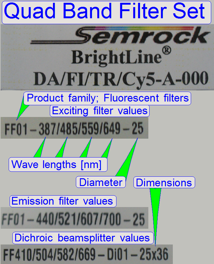
Pannoramic scanners using mainly BrightLine®
Multiband Fluorescence Sets from Semrock, therefore, this will be used as
example also.
Parameters of filter set
|
DA/FI/TR/CY5-A-000 |
||||
|
Name |
Excit |
Emiss |
Dichroic |
Art.
number |
|
DAPI |
387 |
440 |
410 |
HP-FLT-SR07 -QUAD02 |
|
FITC |
485 |
521 |
504 |
|
|
TRITC |
559 |
607 |
582 |
|
|
Cy5 |
649 |
700 |
669 |
|
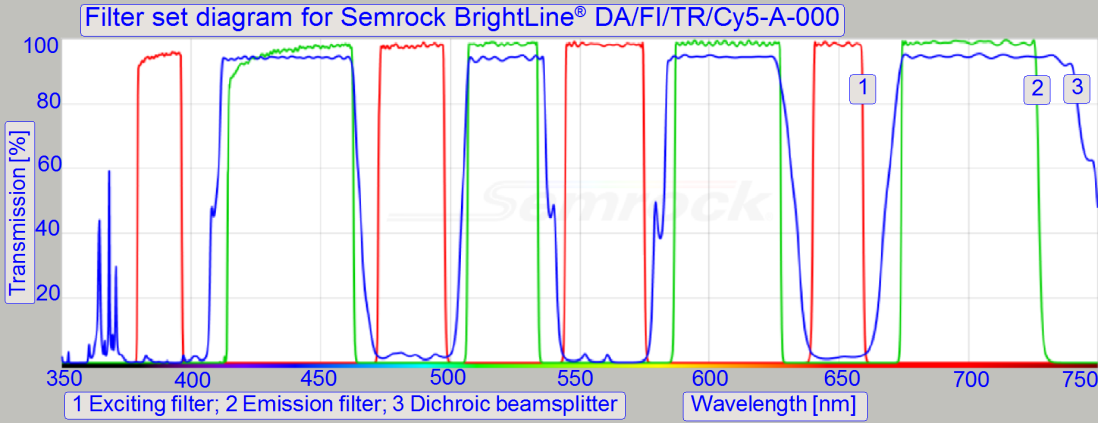
Frequently used fluorophores in conjunction
with quadband filters
![]() Filter set details Semrock
(stored)
Filter set details Semrock
(stored)
Characteristics of camera
sensor
|
Scan
camera |
|
|
Name |
Chroma |
|
Adimec Q-12A180 |
|
|
PCO.edge 5.5Mp |
|
|
PCO.edge 4.2Mp |
|
|
AxioCam MRm Rev.3 |
|
|
GS3-U3-51S5M |
|
|
CIS VCC-F52U25CL |
|
|
CIS VCC-FC60FR19CL |
|
|
Stingray F146C |
|
|
Marlin F146C |
|
|
|
|
|
Sony DFW-X710 |
|
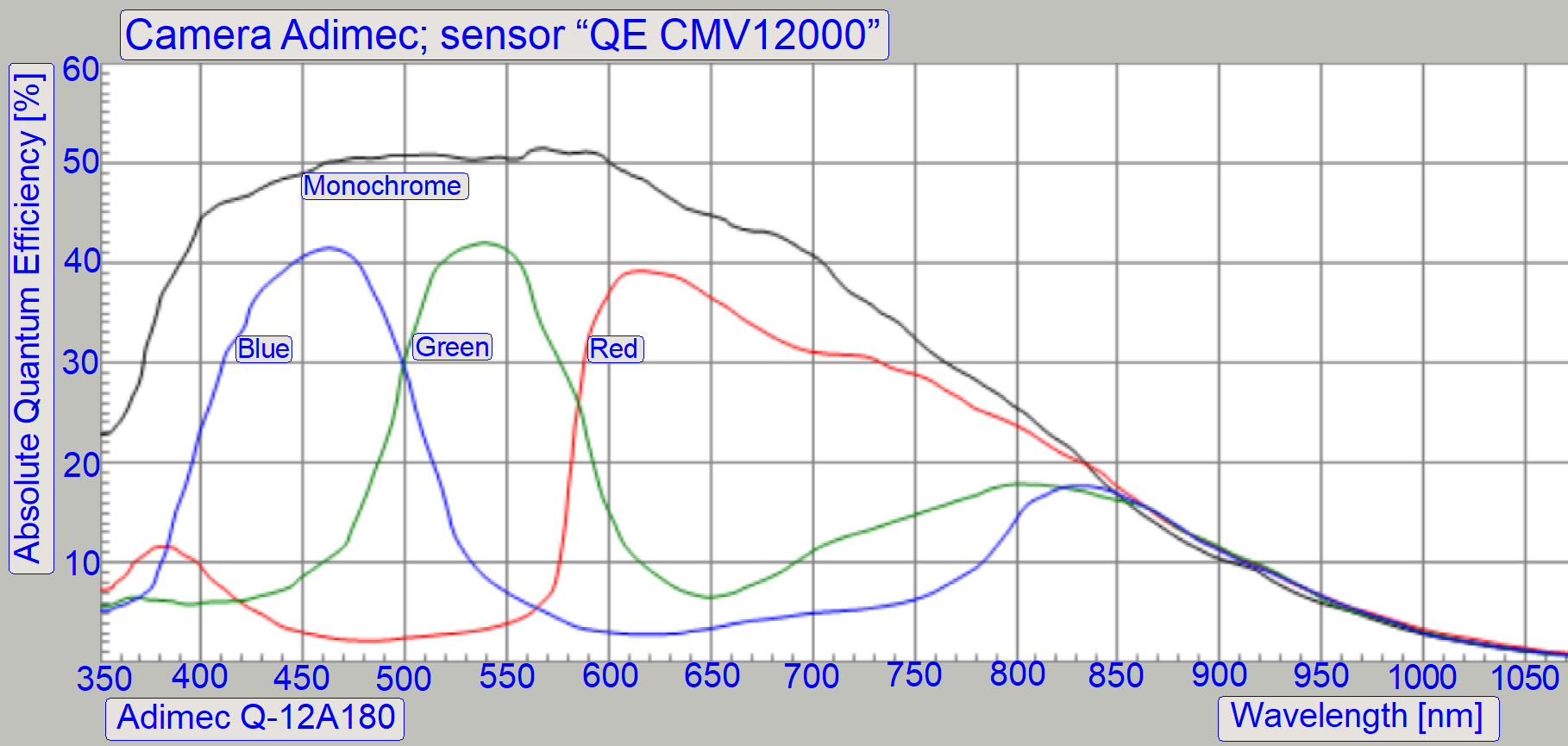
Remark
The original sensor characteristics of the cameras can
be found in the descriptions of the cameras.
Principles of exciting
and imaging
White light source
 Traditionally,
exciting of specimens is done from a white light source with exciting
wavelength range of 350nm to 800nm.
Traditionally,
exciting of specimens is done from a white light source with exciting
wavelength range of 350nm to 800nm.
By using wavelength filters, the required exciting wave
length (range) is filtered from the white light and this is used to excite the
fluorophore via the filter block and the objective.
Generating the exciting wavelength by filtering from
white light requires a filter block for each fluorophore separately, this
means, if the exciting wavelength is changed, the filter block has to be
exchanged also.
Because the emitted light is very low in intensity,
the exposure time of the camera is increased, in relation to the brightfield
image and if there e.g. 4 stains are used, 4 images of the same FOV is taken,
each with another filter block.
The filter block has to be moved every time into the
image path. Therefore, scanning of a stained FOV may take several seconds; a
small tissue of several 100 FOVs may take 10 … 20minutes.
·
As discussed before, the scan time of a
FOV is the sum of exposure time for each FOV and the time for the filter block
exchange.
To increase the scan speed, the time for filter
exchange is minimized by using multiband filters in the filter block.
To increase the scan speed, the time for filter
exchange is minimized by using multiband filters in the filter block.
To increase the scan speed, the time for filter
exchange is minimized by using multiband filters in the filter block.
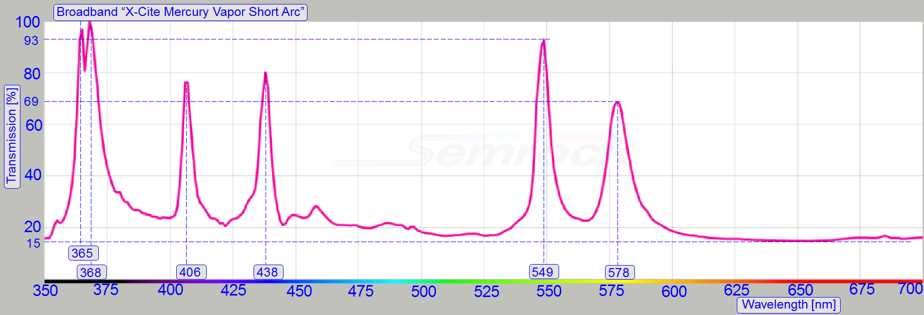
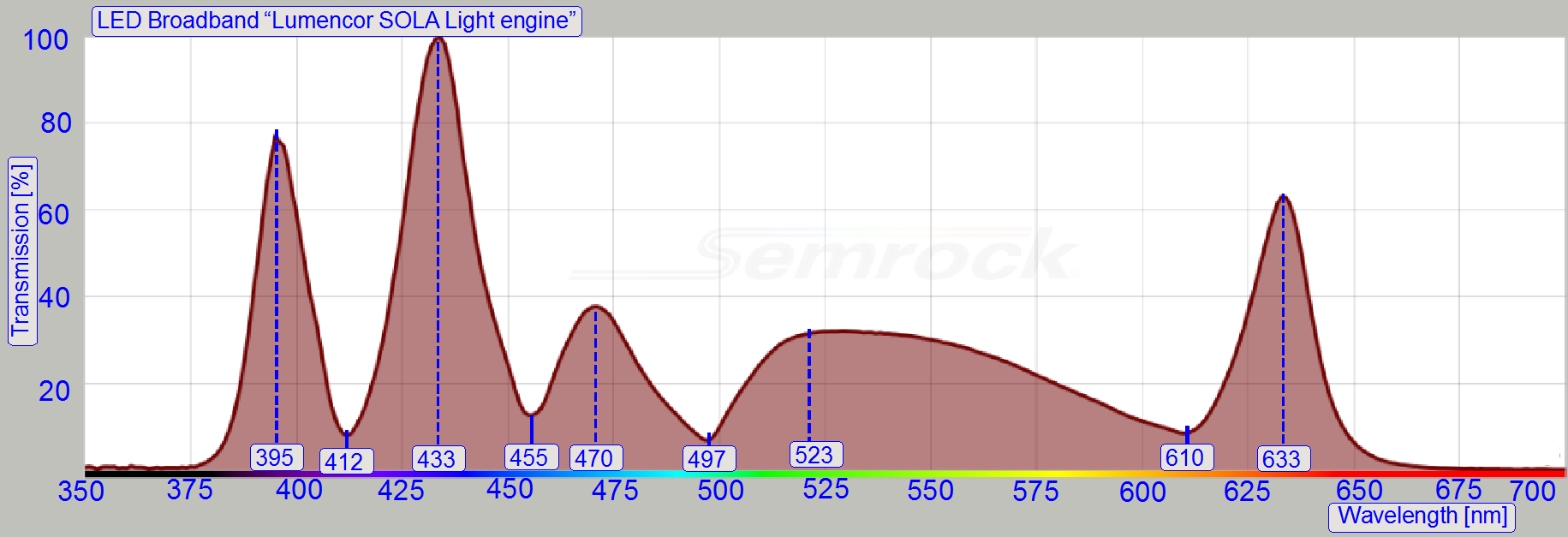
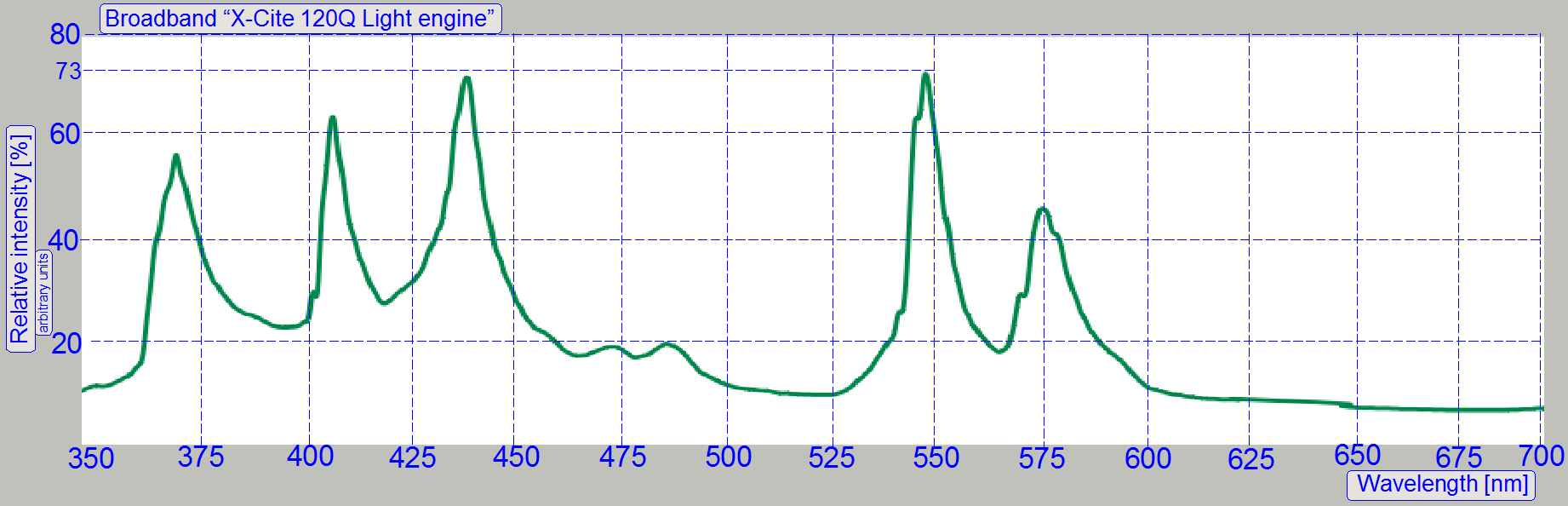
Light sources, that creating white light is the “X-Cite type
Series”, HXP 120 and the more cost effective “SOLA-SM-II-Light-Engine”
If the light source creates white light, only single
band filters can be used. The light wave length filters in the filter cube are
filtering out all unused light wavelengths and only the desired, special
wavelength will be used to excite the specimen.
The filter block creates a single monochrome
wavelength from the white light for exciting the specimen. Each required
wavelength requires also a separate filter block to create the desired
monochrome light wavelength.
For this purposes, the turret unit has 10 positions
and is able to handle 9 filter blocks for fluorescent scan operations.
Introduction to Fluorescence Filters Semrock
Monochrome light excitation
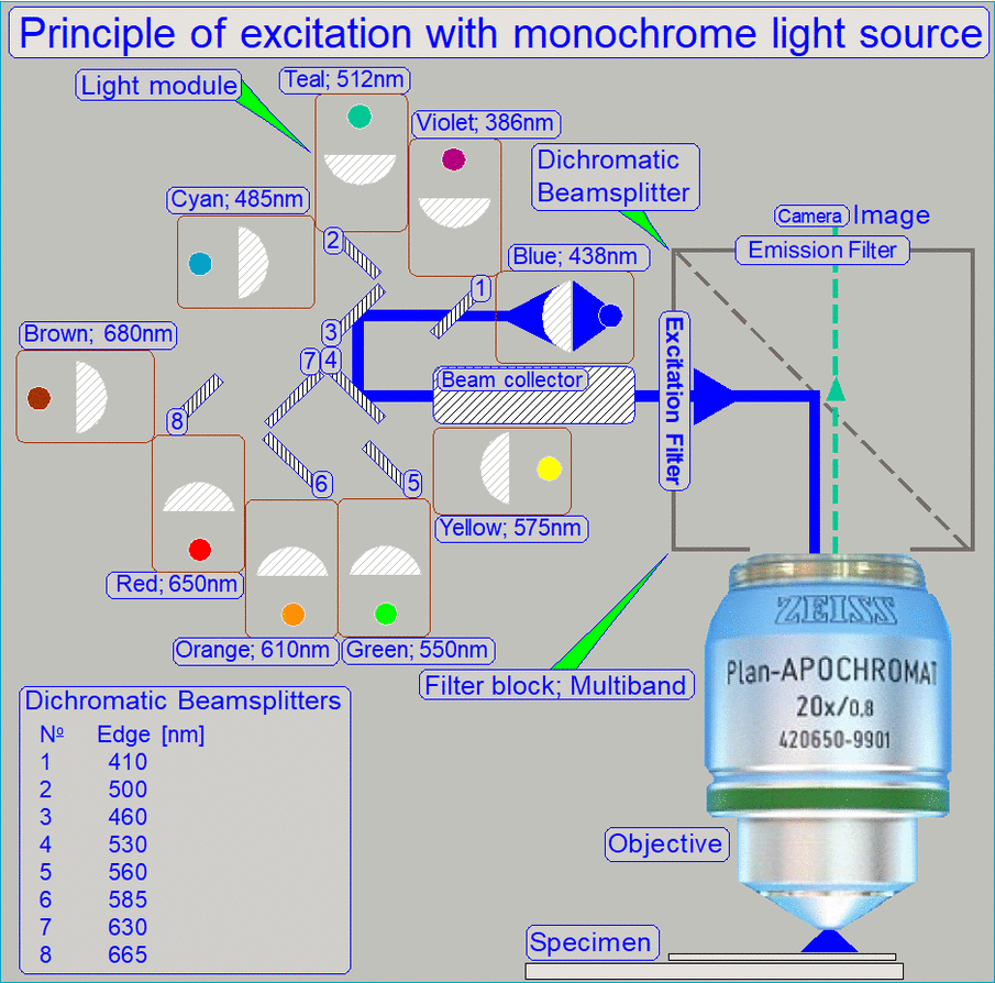 The
principle of monochrome excitation includes the creation of exciting
wavelengths separately. The light source (light module) creates the light
wavelength as required for the fluorophore.
The
principle of monochrome excitation includes the creation of exciting
wavelengths separately. The light source (light module) creates the light
wavelength as required for the fluorophore.
By using multiband filters (e.g. Quad band filters), 4
exciting wavelength can be filtered with the same filter block, without moving
the filter block. This way FOV scan time is saved, because there are no
mechanical movements of the filter block.
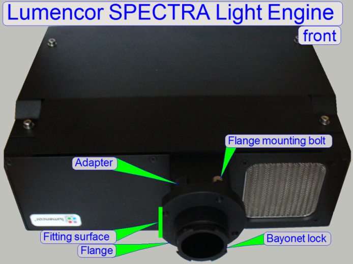
Light source, which create monochrome light is the
“Lumencor SPECTRA light engine”.
The main difference is, that the light source creates
the required monochrome light wavelengths separately and these can be switched
on or off as required very quickly.
Because the exciting light is monochrome, multi
channel filters can be used and so, the movement of the filter blocks is
practically eliminated.
Exciting light source
To excite the fluorophore it will be illuminated with
very high intensity light by using a special wavelength, the exciting
wavelength of the fluorophore. The
required wavelength of the light is supplied by special excitation lamps.
![]() Fundamentals of Metal Halide Arc Lamps Link
Fundamentals of Metal Halide Arc Lamps Link
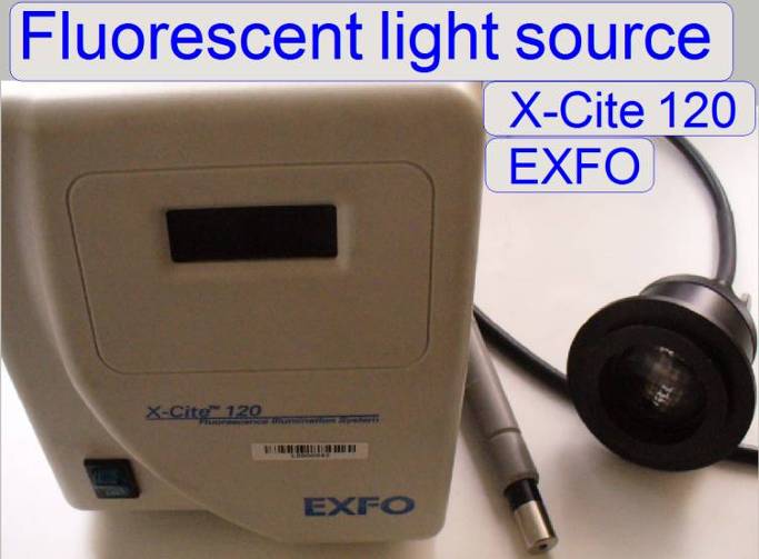
HXP 120
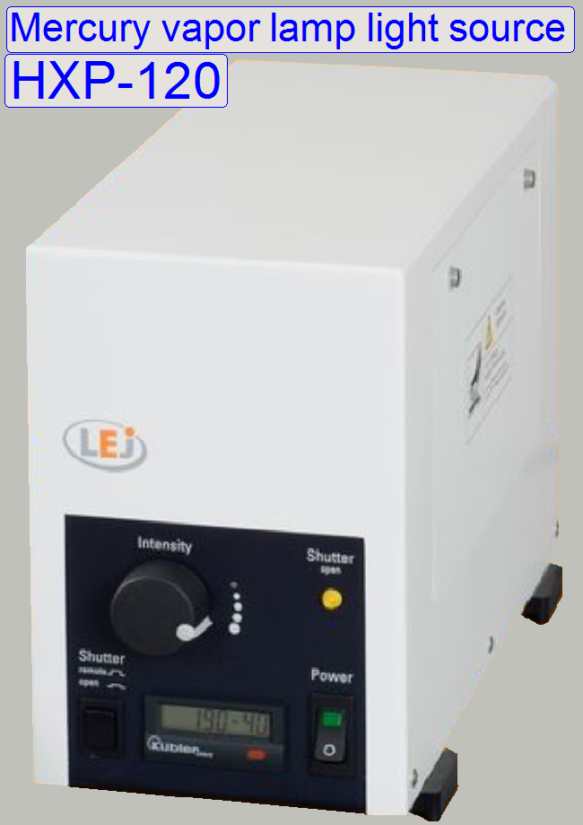
Mainly used in: MIRAX
SCAN and MIRAX
Metall halide fluorescence light source. Connected via liquid light
guide, Vibration free with integrated shutter, software controlled.
![]() Light Electronics
Light Electronics
LQ-HXP 120 Manual (stored)
·
By calculating of components, the emitted wavelengths
of the light source is important!
X-Cite 120
Creation
of white light
In Pannoramic configurations 2 types are used.
![]() Light sources main page
Light sources main page
 Precautions (stored)
By calculating the parameters of components, the emitted excitation
wavelengths of the light source are important!
|
|
SOLA-SM-II-Light-Engine
Used in: P250, SCAN and
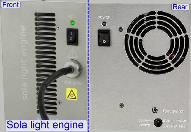
Sola-SM-II-Light-Engine® offers a more cost-effective solution in
relation to the HXP-120 Light Source® or to the Lumencor SPECTRA light engine®
and may be used in Fluorescent scan sessions of any scanner type.
- Because the
Light engine emits white light, only single band filters can be used.
Filter
Set Recommendations  Semrock
By calculating of
components, the emitted excitation wavelength of the light source is important!
|
|

Lumencor SPECTRA
light engine
Used in: P250, SCAN and
|
Early delivered Lumencor SPECTRA |
||
|
Color
channel |
Bandpass /width |
Range |
|
[nm] |
[nm] |
|
|
Violet |
386/23 |
375
~ 398 |
|
Blue |
438/24 |
426
~ 450 |
|
Cyan |
485/20 |
475
~ 495 |
|
Teal |
512/25 |
499 ~ 525 |
|
Green |
550/88 |
506 ~ 594 |
|
Yellow |
N/A |
N/A |
|
Red |
650/13 |
643
~ 657 |
|
nIR |
Not implemented |
|
Real values see Certificate of conformance for connected component.
|
New spectrum; Lumencor SPECTRA |
||
|
Color
channel |
Bandpass /width |
Range |
|
[nm] |
[nm] |
|
|
Violet |
390/22 |
379
~ 401 |
|
Blue |
438/29 |
424
~ 453 |
|
Cyan |
475/34 |
458
~ 492 |
|
Teal |
513/22 |
502 ~ 524 |
|
Green |
542/33 |
526 ~ 559 |
|
Yellow |
575/35 |
558 ~ 593 |
|
Red |
631/28 |
617
~ 645 |
|
nIR |
Not
implemented |
|
|
Values for
orientation only. Real values see Certificate of conformance for connected
component. |
||
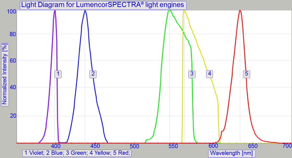
By calculating components, the emitted wavelength of the light source is
important!
|
Light engines,
selection |
|
Light engine |
This part should help you to select the right
components for powerful FL scanning equipment, beginning from different
circumstances.
Fluorophore, Filter set and Light source
 As
discussed before, the wavelengths ranges of the components should be matched
optimally to reach best possible scan quality; this means:
As
discussed before, the wavelengths ranges of the components should be matched
optimally to reach best possible scan quality; this means:
The wavelength range intersection of the
- fluorophore's
exciting wavelength,
- the
wavelength of the exciting filter and
- the
wavelength of the exciting light source
should be as much as possible.
The wavelength range intersection of the
- fluorophore's
emission wavelength range,
- the emission
wavelength range of the filter and
- the
wavelength spectrum of the camera
should be as much as possible.
New system
Starting with the fluorophores
- The user should
provide a list of frequently used fluorophores.
- Make a table
with the exciting and the emission wavelength
- decide the
light source, white light or monochrome excitation
- decide the
filters; single band, multi band and exciting and emission spectra
- Define the
scan camera type
- While
defining the components for the system some modifications may be required.
- If in the
list of the user's fluorophores are items, that can not be excited with
the planned light source or can not visualized with the planned camera,
discuss these items with the user.
- Keep in mind,
that the components of the system are expensive, so lifetime and
maintenance costs may be relevant.
Existing system
In an existing system we assume, the filter blocks,
the excitation light source and the camera are existent.
- Compare the
emission spectrum of each filter block with the spectrum of the camera
- Make a table
of emission spectrum and exciting spectrum of the filter blocks.
- find useable
fluorophores depending on the spectrum of the light source and the
spectrum of the filter block's filters.
Links
SearchLightTM Introduction Semrock
SearchLightTM Analysing and plotting tool Semrock
The SearchLightTM Analysing and plotting
tool can be used to compare exciting and emission wavelengths of filters
(sets), fluorophores and light sources.
Further links
To find filters, fluorophores, Light engines and
optimizing component selection for the user's requirements and also for
planning of fluorescent scan systems, the following links may help.
ATT Bioquest Home page
Chroma Filter sets
Semrock Set Details