Optics, illumination; PCON
For technicians and partly for sales managers!
This chapter handles the components of the brightfield illumination and
the brightfield image path for the scanner Pannoramic Confocal. Because our
products are developed continuously, some items in the shown menus may differ
to the actual software version you are using.
The description is based on the software version 1.19.
To help resolve problems with illumination and optics, a hardware
description of the implemented components and adjustment procedures are added.
Contents
Brightfield
illuminated optical path
Configure
light sources and units
Brightfield
RGB illumination unit
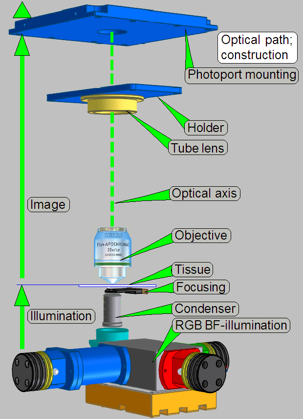
 The optical path
includes the following components:
The optical path
includes the following components:
- Condenser
- Slide, tissue,
coverslip
- Immersion
Liquid Feeder
- Objective
- Objective changer
- Tube lens,
60N photo port
- Aurox Confocal unit
- Camera adapter
- Scan camera
Brightfield illuminated
optical path
RGB
illumination
 The construction
of the BF optical path uses only a monochrome camera, the camera PCO.edge
5.5MP, so only monochrome images can be produced.
The construction
of the BF optical path uses only a monochrome camera, the camera PCO.edge
5.5MP, so only monochrome images can be produced.
To create color information of the tissue with a monochrome camera, we
illuminate the tissue with monochrome light.
If the tissue is illuminated by blue light, and we are making an image
of the Field of view, the gray scaled camera image contains the intensity of
the blue parts in the tissue.
Because the pixel resolution of the camera is very high and the gray
scale of the image is made by 14bit per pixel, very detailed information of the
blue part in the FOV related to the appropriate pixel can be reached.
If we repeating the procedure with the colors Green and Red, 3 images of
the same FOV are produced and so, the software knows detailed color information
about each pixel of the Field Of View.
By using the software coloring method the true color information of each
pixel is found.
By using cameras with a large image sensor low shutter time and high
resolution, the scan time of the tissue can be held in acceptable boundaries
and the result is an image with high resolution and high color fidelity.
Brightfield
image path
 The light, passed
thru the tissue is collected by the objective.
The light, passed
thru the tissue is collected by the objective.
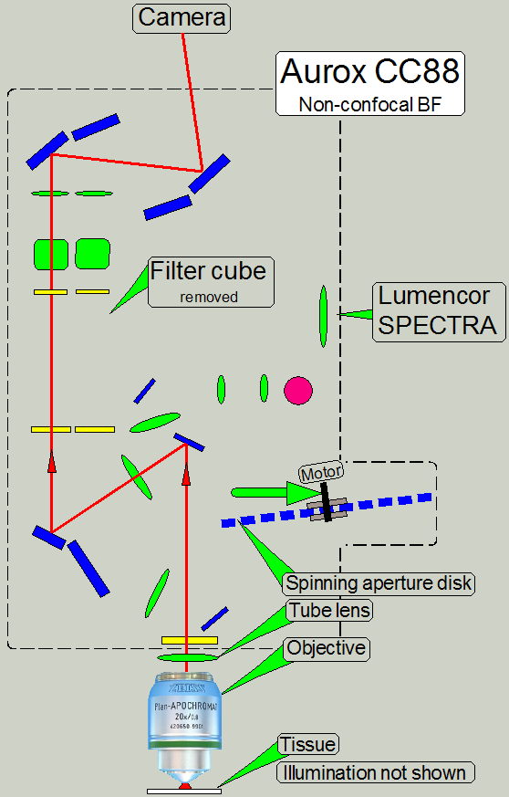
The image, created by the objective together with the tube lens, arrives
to the imaging system Aurox CC88.
The spinning aperture disk is moved sideward and will not be used to
produce the brightfield illuminated image.
The image is prepared by lenses and mirrors and will arrive to the
camera.
· In the brightfield
image path a filter cube must not be inserted!
The image, seen by the objective, illuminates only one half of the
camera’s image sensor.
The CCD of the camera transforms the incoming light into electrical
charge, this is read by the electronics of the used camera; and the composed
data stream (the image) is transferred to the software.
Configure light sources and
units
· The
path of the file MicroscopeConfiguration.ini, in the software version with the
operating system Windows® 7 is:
C:\ProgramData\3DHISTECH\SlideScanner\MicroscopeConfiguration.ini
[Microscope]
SerialNumber=PCON_xxx
MicroscopeType=3DMic10
MicroscopeSubtype=Confocal
ScanCameraType=
PreviewCameraType=CVrmc_m8_pPro
BarcodeReaderType=PreviewCamera
LoaderType=SL_1Mag_12Slide_Sensor_Horizontal2
CameraChangerType=CC_none
ReflectorTurretType=RT_None
BrightfieldLightSourceType=RGBLedLight
ObjectiveChangerType=OC_2Pos
ObjectGuideXYZType=OGXYZ_FLASH4
FlashUnitType=NoFlashUnit
NDFilterType=NDType_None
PreviewLightType=PreviewLightUnitType_Type2
ShutterMotorType=Shutter_Motor
PowerSwitchBoardType=PowerSwitchBoard_Type1
ConfocalUnitType=ConfocalUnitType_Aurox
WaterFeederType=WaterFeeder_Type1
 Brightfield
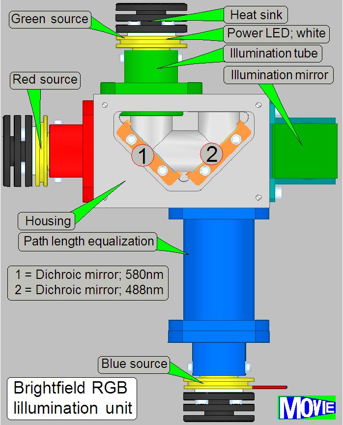
RGB illumination unit
Brightfield
RGB illumination unit
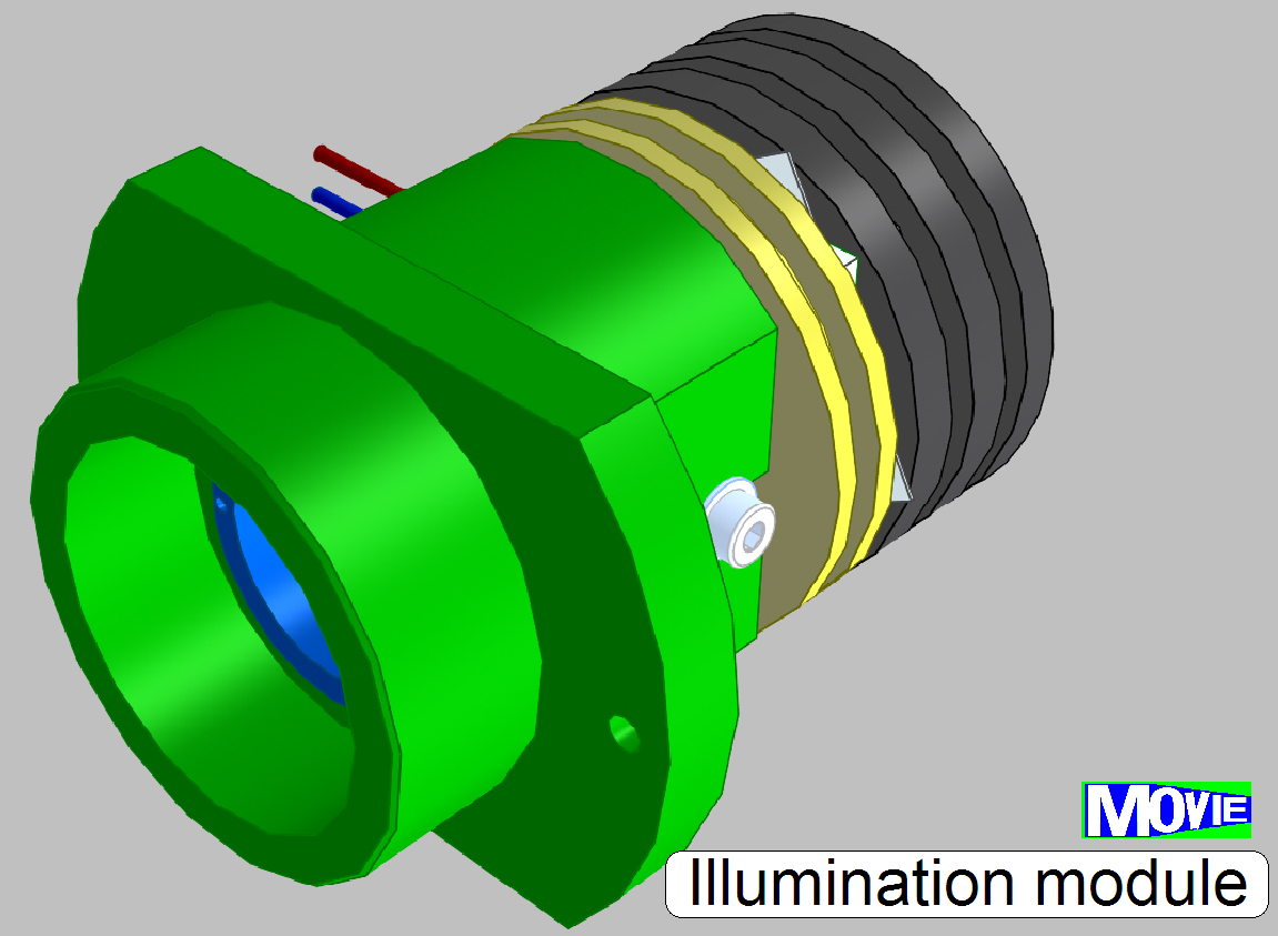
The
illumination unit consists of:
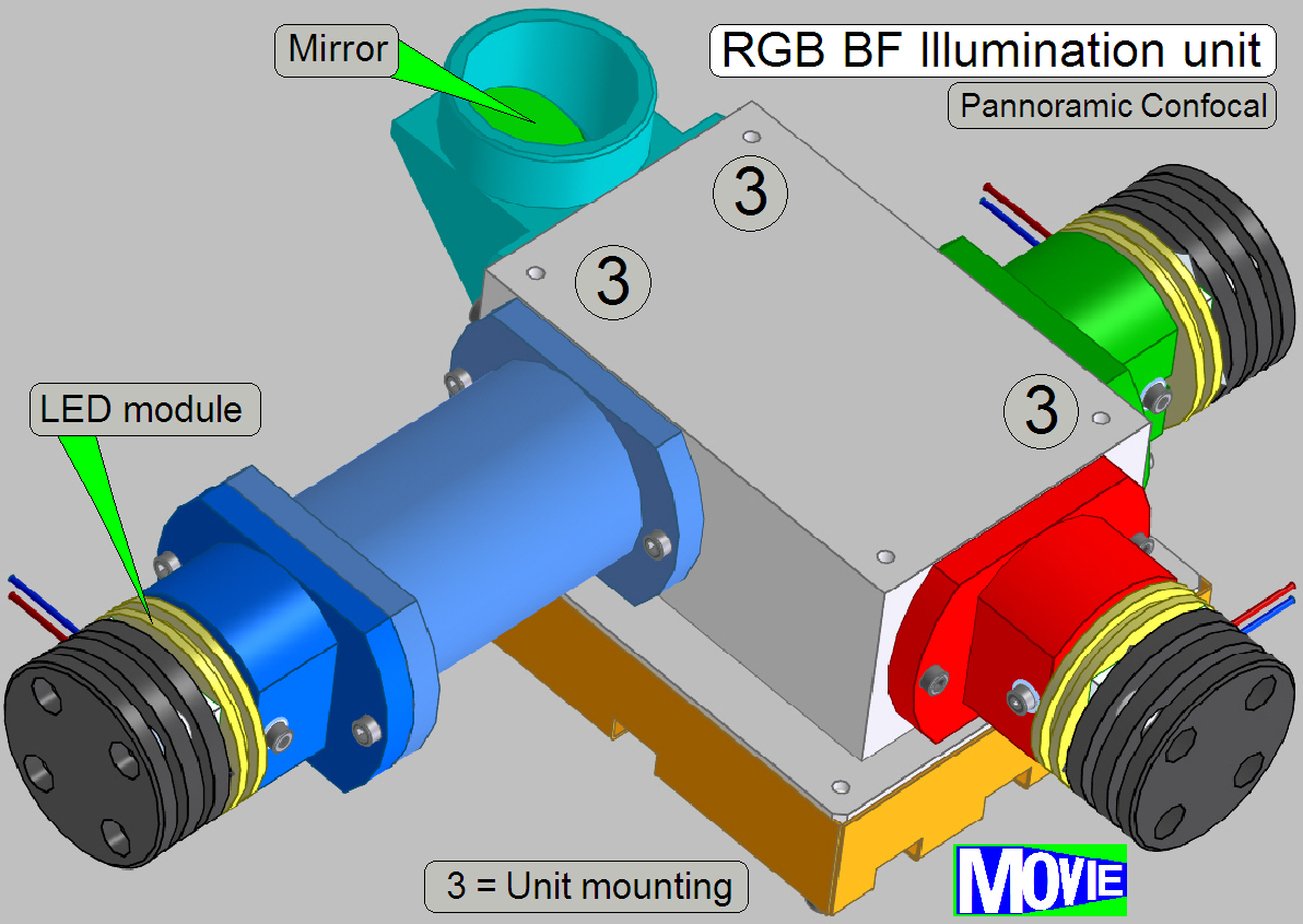
 Housing
with:
Housing
with:
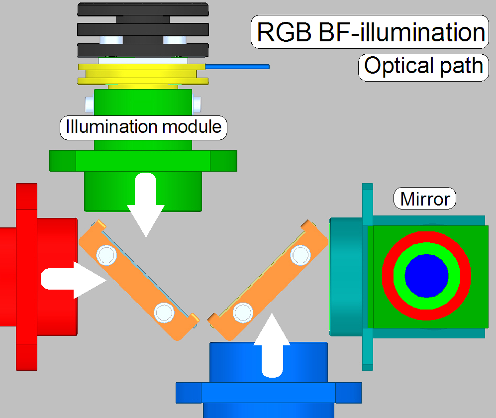
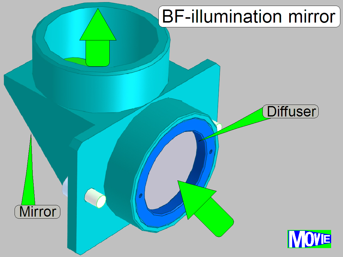
· two dichroic beamsplitters to
route the light rays of Red, Green and Blue to the BF illumination mirror
· Dichroic beamsplitters
are mounted in an angle of 45º in relation to the light sources
· the mounting of illumination modules
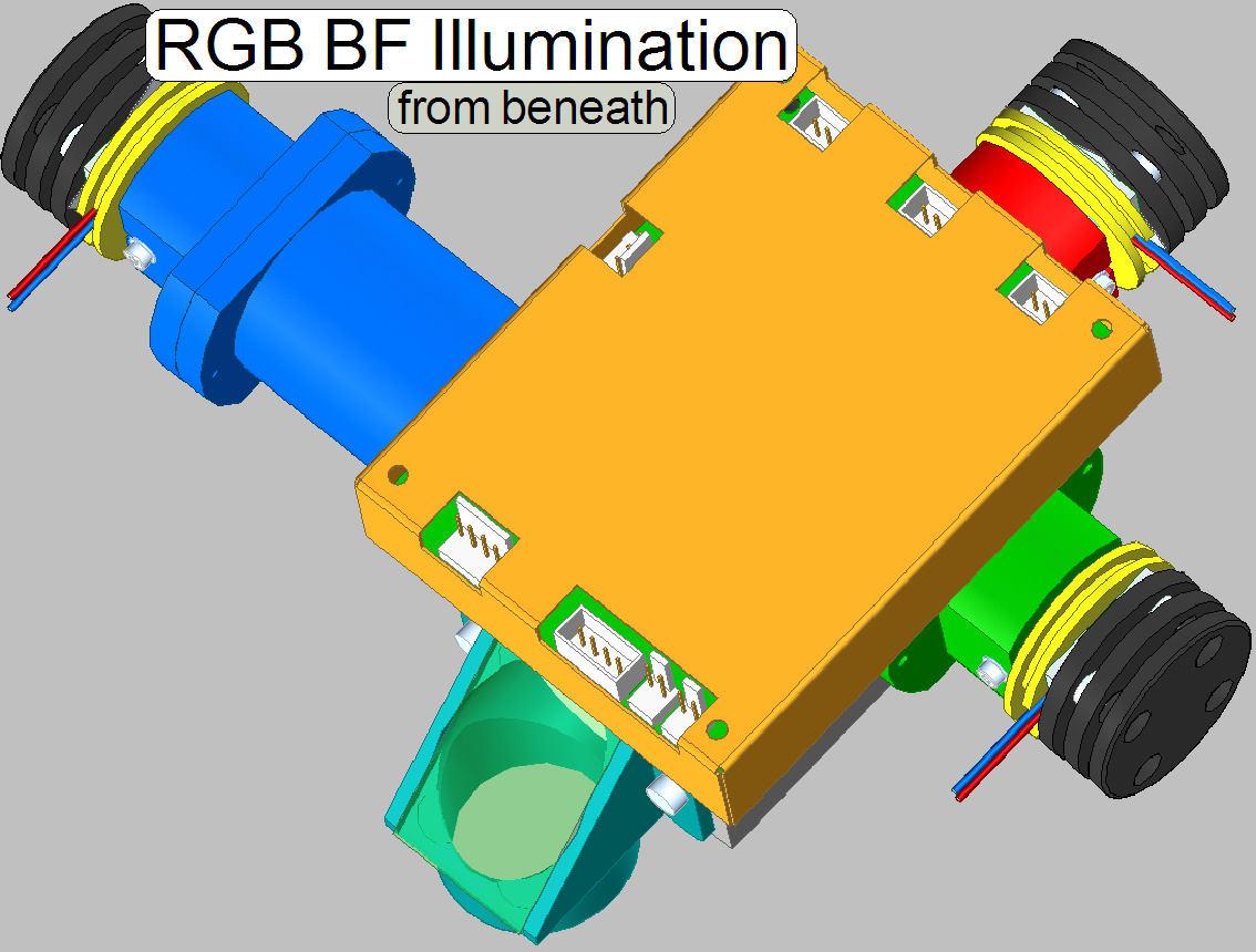
· Illumination mirror with
diffuser
· Mountings to the
scanner plate of the PCON; see image above
· Electronics (power supply and control of
the LEDs; not shown here)
· The illumination
components are mounted to the Illumination unit housing by bolts!
· Adjustments are
not required.
· Maintenance is not
required.
See also: “Illumination Gallery”
Used beamsplitters
· The Dichroic
beamsplitters are always mounted in an angle of 45º in relation to the
light sources and the optical axis
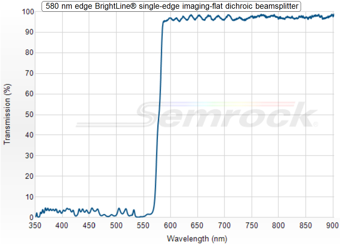 Dichroic
beamsplitter 1; 580nm
Dichroic
beamsplitter 1; 580nm
· All light
wavelengths above 580nm (the red and orange part of the visible light) passing
thru the dichroic beamsplitter; all wavelengths below 580nm, the yellow, green,
blue and violet light, will be reflected.
In other words:
· The lower
wavelengths, below 580nm are always reflected while the higher wavelengths,
above 580nm pass through the beamsplitter!
Part Number: FF580-FDi01-25x36
Dichroic
beamsplitter 2; 488nm
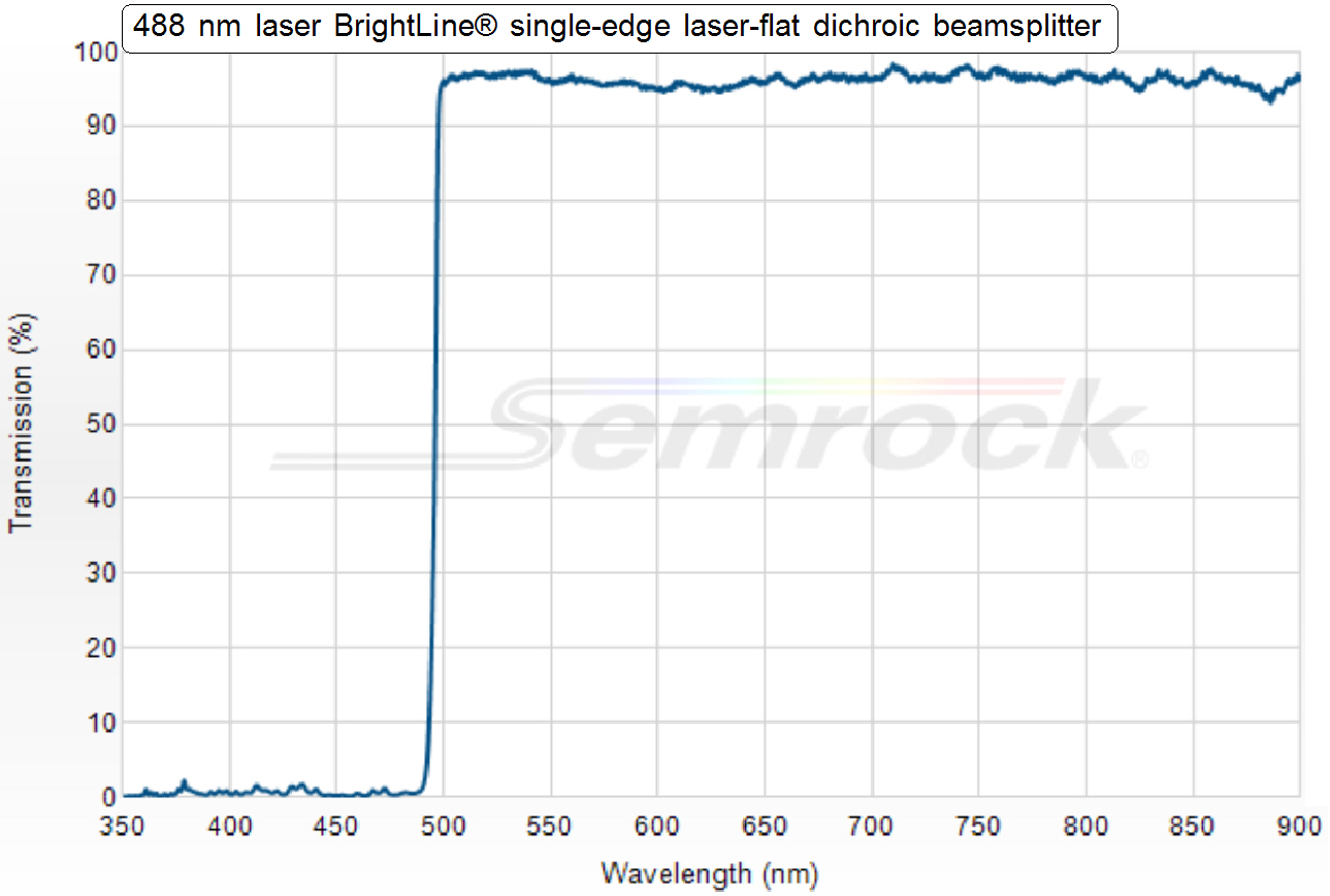
· All light
wavelengths above 488nm (the red, yellow and green light) passing thru the
dichroic beamsplitter all wavelengths below 488nm, the blue and violet light,
will be reflected.
In other words:
· The lower
wavelengths, below 488nm are always reflected while the higher wavelengths,
above 488nm pass through the beamsplitter!
Part Number: Di02-R488-25x36
By using the dichroic beamsplitters the required wavelengths for the
colors Red, Green and Blue can be filtered from the white light, emitted by the
LED.
· 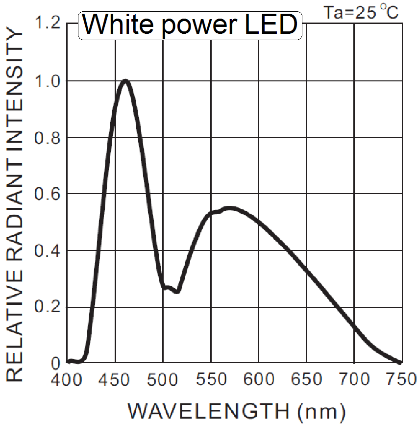 Also important in
this construction is the emitted wavelength spectrum of the white power LED.
Also important in
this construction is the emitted wavelength spectrum of the white power LED.
· The violet light,
in the range from 390 ~ 420nm does practically not exist.
· The visible white
light is defined in the range of approximately 400 ~ 700nm.
Significant colors can be assumed in the following
wavelength ranges
|
Color |
Range |
Typical |
|
[nm] |
[nm] |
|
|
Violet |
390 ~ 430 |
410 |
|
Indigo |
430 ~ 450 |
440 |
|
Blue |
450 ~ 495 |
460 |
|
Green |
500 ~ 560 |
535 |
|
Yellow |
560 ~ 590 |
575 |
|
|
590 ~ 620 |
610 |
|
Red |
620 ~ 690 |
660 |
Illumination path
 The illumination
module creates always white light in the wavelength range of ~400 to 700nm.
The illumination
module creates always white light in the wavelength range of ~400 to 700nm.
· The shown color of
the illumination tube is only used to show the arrangement of the light sources
in relation to the beamsplitters.
· The illumination
modules are switched on separately, so only 1 wavelength range will be created
at a time.
· Detailed
information about the working principle will be shown in the following.
The
Red light source emits light in the range of 400 ~ 700nm
· 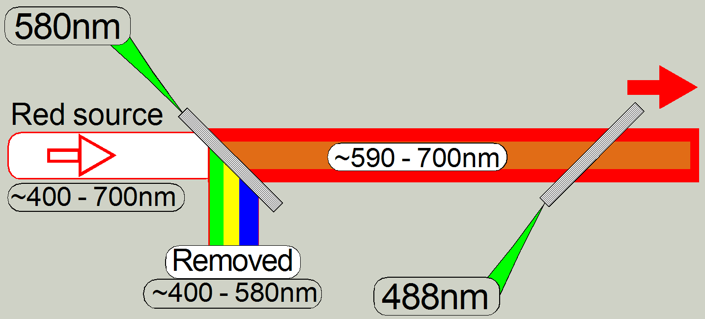 The unwanted
wavelength range from 400 ~ 580nm (yellow, green and blue) will be filtered out
(reflected) by the dichroic beamsplitter with a nominal wavelength edge of
580nm.
The unwanted
wavelength range from 400 ~ 580nm (yellow, green and blue) will be filtered out
(reflected) by the dichroic beamsplitter with a nominal wavelength edge of
580nm.
The
Green light source emits light in the range of 400 ~ 700nm
· 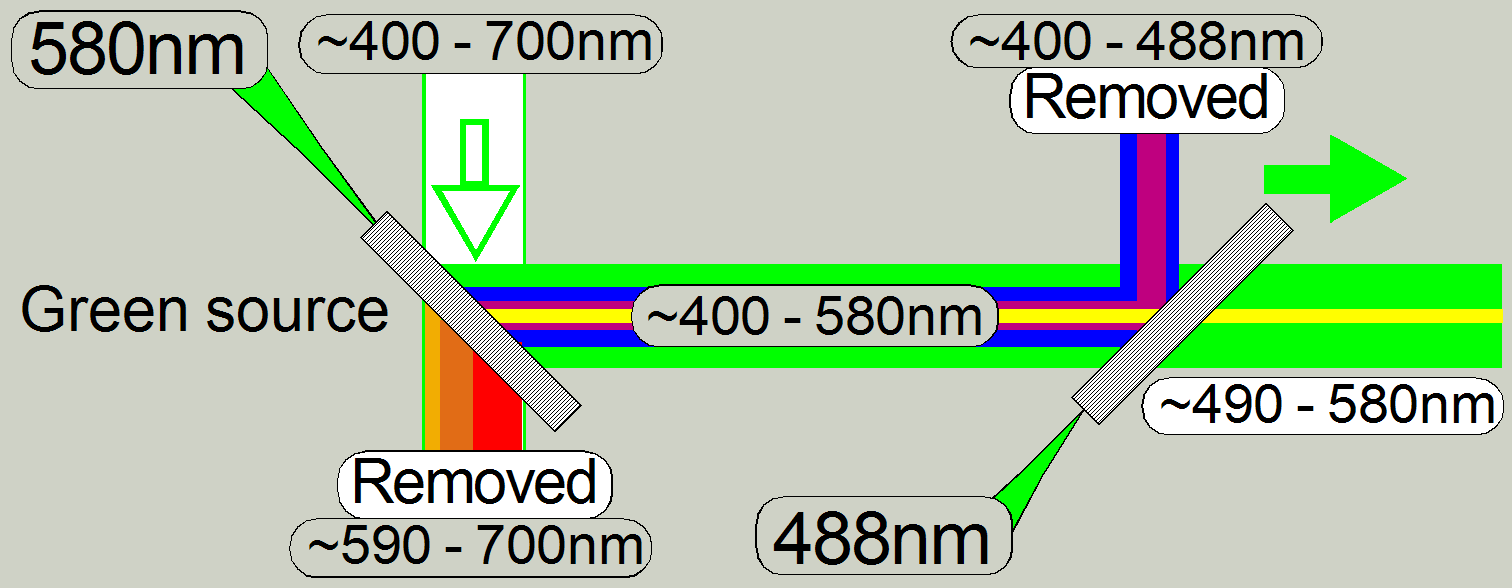 The unwanted
wavelength range from 590 – 700nm (yellow, orange and red) will be filtered out
(passes thru) by the dichroic beamsplitter with a wavelength edge of 580nm.
The unwanted
wavelength range from 590 – 700nm (yellow, orange and red) will be filtered out
(passes thru) by the dichroic beamsplitter with a wavelength edge of 580nm.
· The blue part will
be filtered out (reflected) by the dichroic beamsplitter with a wavelength edge
of 488nm.
The
Blue light source emits light in the range of 400 ~ 700nm
· 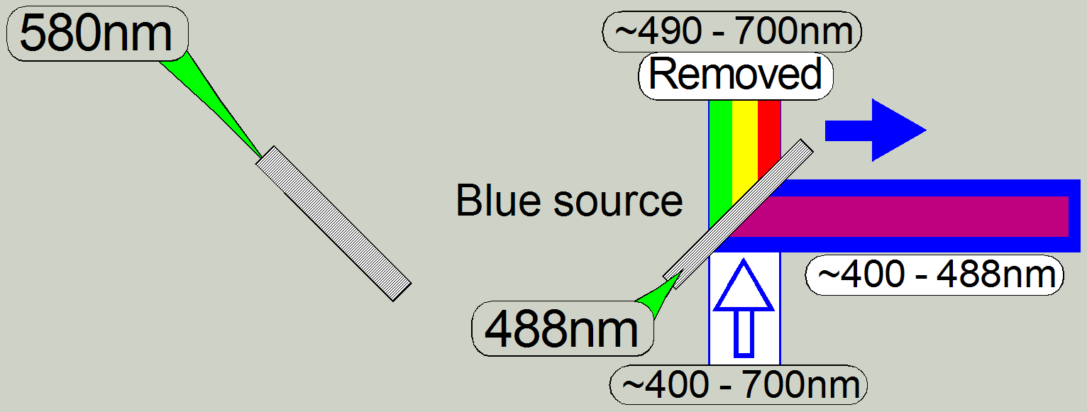 The dichroic
beamsplitter would also reflecting violet light, but because the power LED emits
only blue light (from about 420nm) in practice, the violet part does not exist.
The dichroic
beamsplitter would also reflecting violet light, but because the power LED emits
only blue light (from about 420nm) in practice, the violet part does not exist.
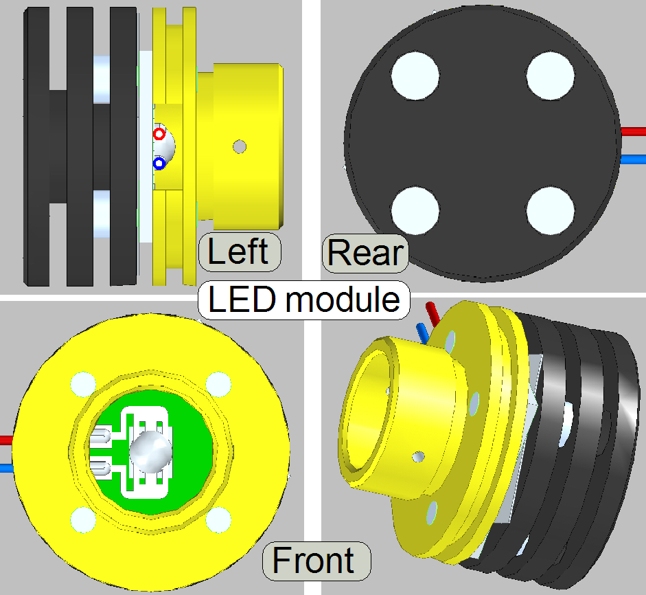 The
power led module creates white light and is used to illuminate the Field Of
View (FOV) in the brightfield scan mode.
The
power led module creates white light and is used to illuminate the Field Of
View (FOV) in the brightfield scan mode.
· Because
the brightfield image is created from the colors RGB the module exists 3 times
in the brightfield illumination unit; the wire color is used to find the
appropriate connector easily.
The pulse frequency may be more than hundred Hz; it
means, the scan camera can make more than 100 images /second.
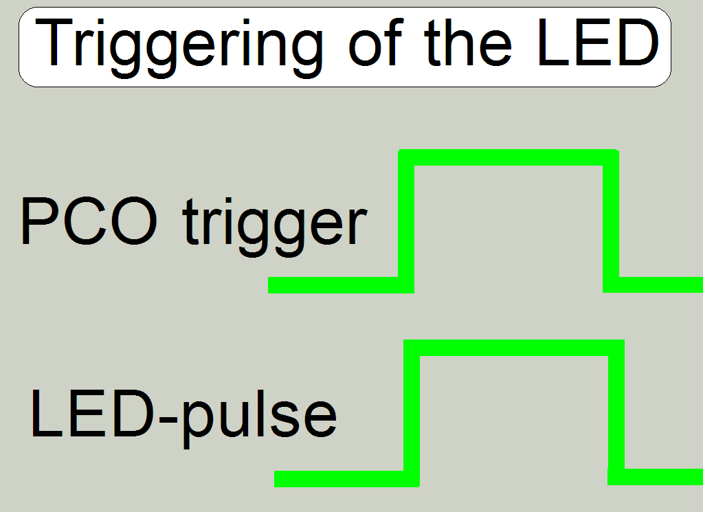 To switch on the
LED during the camera is ready; the led module is triggered (synchronized) by
the PCO.edge camera.
To switch on the
LED during the camera is ready; the led module is triggered (synchronized) by
the PCO.edge camera.
· The LED module is
inserted into the Illumination tube until it stops!
· Adjustments are
not required.
· Maintenance is not
required.
See also: “RGB BF scan illumination”
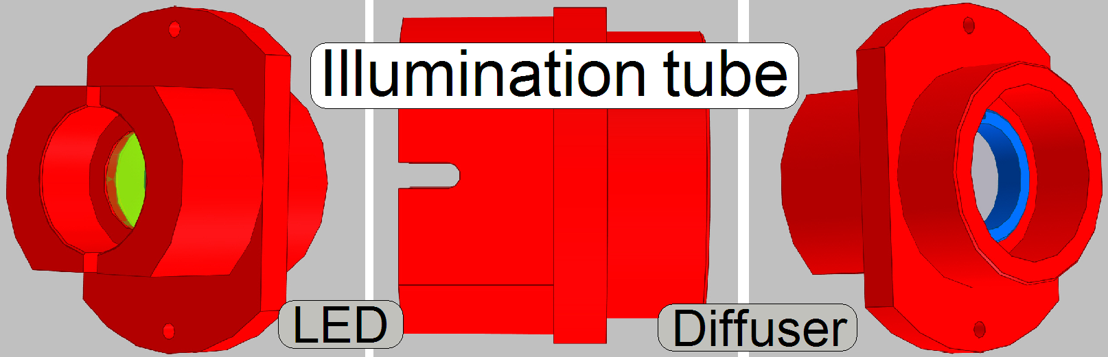 In microscopes and
scanners as well, the illumination
of the tissue is very important. The illumination tube contains the optics to
produce light with a high density and coherent rays; so, the field of view can
be illuminated evenly.
In microscopes and
scanners as well, the illumination
of the tissue is very important. The illumination tube contains the optics to
produce light with a high density and coherent rays; so, the field of view can
be illuminated evenly.
Because the
brightfield image is created from the colors RGB the illumination tube exists 3
times in the brightfield illumination unit; there are no differences in the
construction.
·  The illumination
tube is mounted to the Illumination unit by 2 bolts!
The illumination
tube is mounted to the Illumination unit by 2 bolts!
· Adjustments are
not required.
· Maintenance is not
required.
· 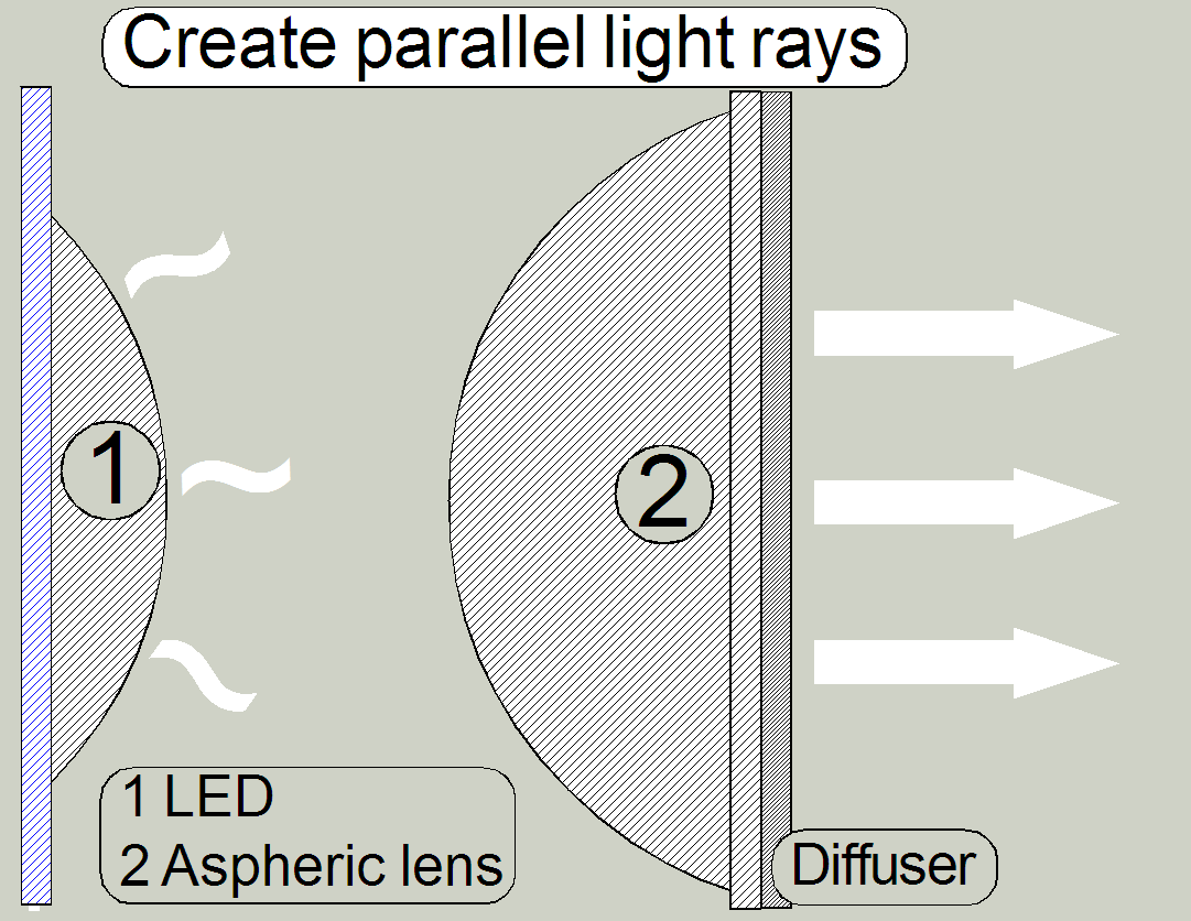 The white light,
emitted by the LED will be collected by the aspheric lens and will be arranged
to parallel light rays.
The white light,
emitted by the LED will be collected by the aspheric lens and will be arranged
to parallel light rays.
· The light rays
crossing the diffuser and are send to the dichroic beamsplitter.
 An
illumination module consists of the LED module and the illumination tube.
An
illumination module consists of the LED module and the illumination tube.
· The Illumination
module does not contain wavelength range filtering components!
· Adjustments are
not required.
· Maintenance is not
required.
· 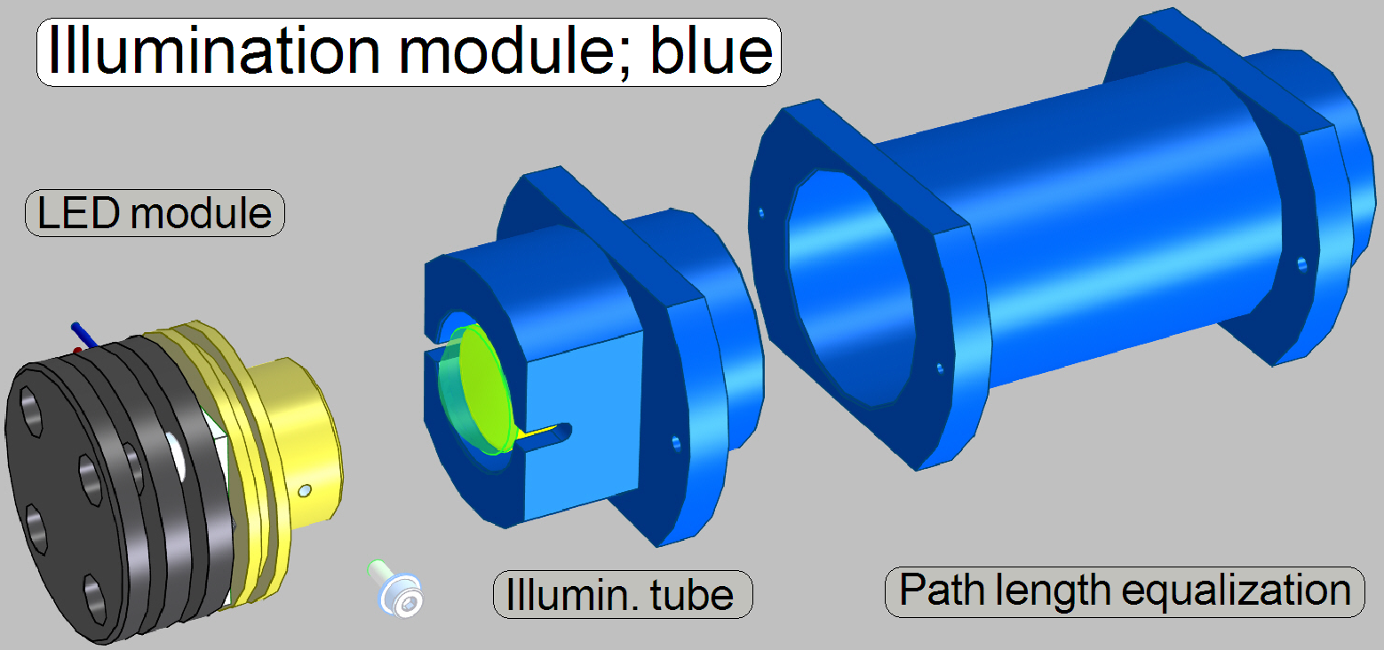 To
ensure, that the distance of the illumination module to the condenser is equal
for all three colors, the light path of blue got a light path length
equalization tube!
To
ensure, that the distance of the illumination module to the condenser is equal
for all three colors, the light path of blue got a light path length
equalization tube!
· The
construction does not contain wavelength range filtering components!
· Adjustments are
not required.
· Maintenance is not
required.
· Adjustments are
not required.
· Maintenance is not
required.
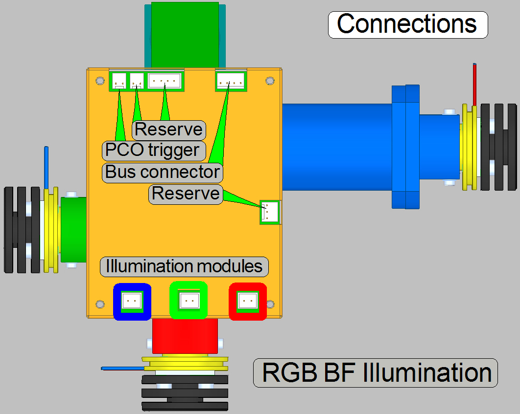
· Connect
the appropriate cable to the specified connector
See also: “Power and control” and “RGB BF scan illumination”
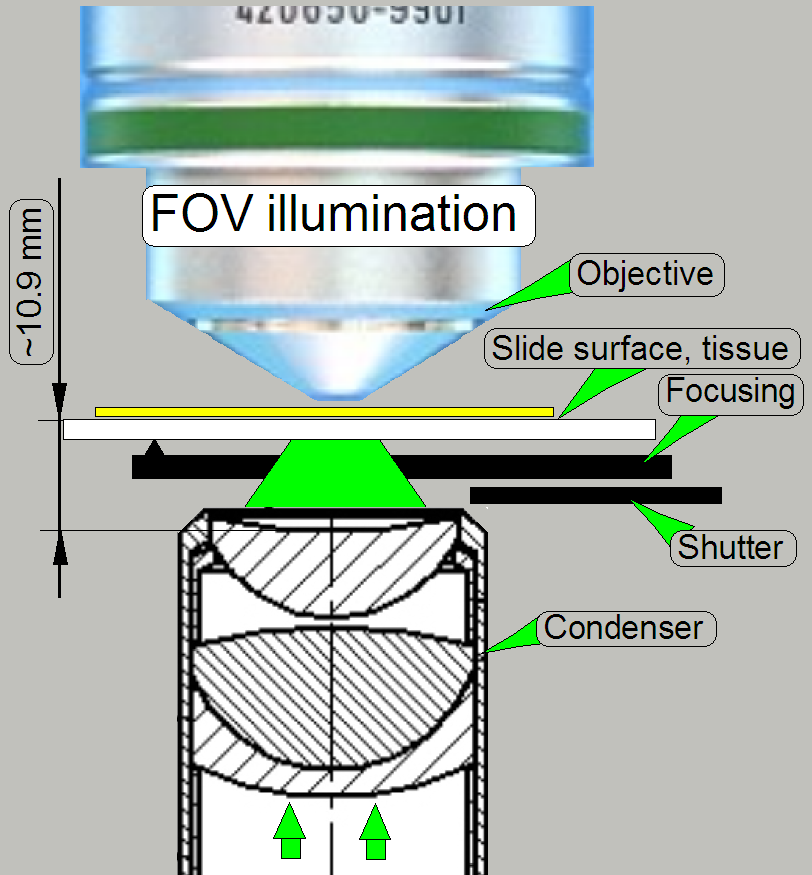
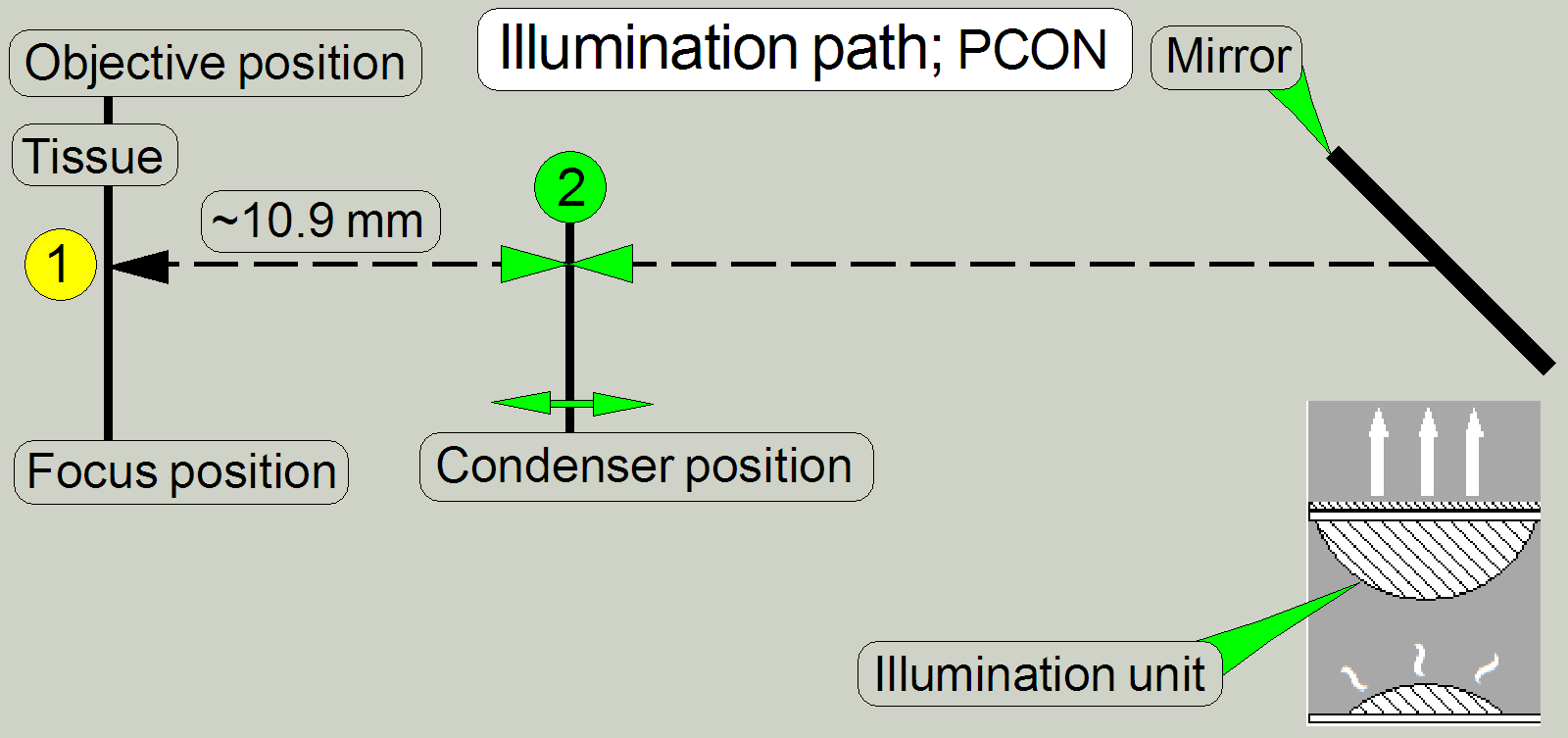
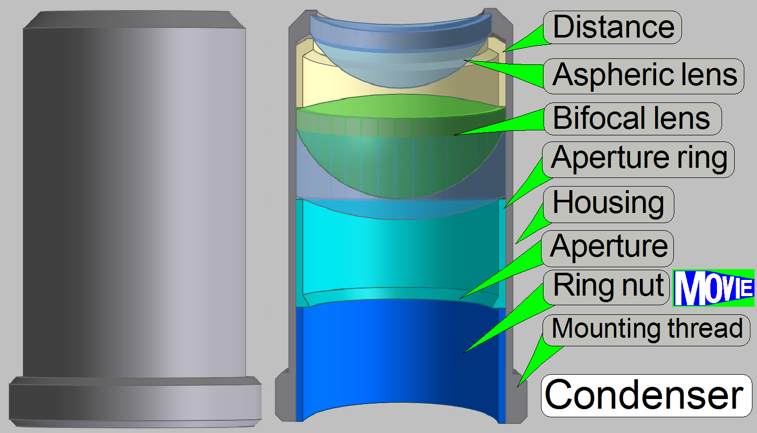 The condenser concentrates
the incoming light to the field of view (FOV).
The condenser concentrates
the incoming light to the field of view (FOV).
Because the size of the illuminated part of the tissue is critical, the
condenser position can be adjusted; the focus position is 10.9mm nominal.
·
See also the “condenser unit” for the condenser position
adjustment.
See also: Condenser ; Wikipedia
· The top of the
cover slip should be clean as possible.
· Please clean the
cover slip before scanning the tissue.
· If the tissue,
scanned with the 40x immersion objective, should be scanned with the 20x
objective also, please dry up the cover slip surface before the objective
exchange will be performed.
Important
If the scan program takes the compensation images after the BF part of
SlideScanner.exe was started and the program stops with the error message
· “The parameter is incorrect”,
please
check the components of the optical path; the camera exposure time is outside
the allowed range!
· The RGB illumination unit
illuminates the tissue in the colors Red, Green and Blue
· Condenser unit with condenser
inserted and condenser’s position is correct
· No filter cube inserted in the
optical path (the position of the filter wheel is empty)
If the scan software SlideScanner.exe shows the error message
· “Error occurred”
and stops working, please read the
temperature values with the service program!
· See
also: “Temperature
sensor, fan and fan control”
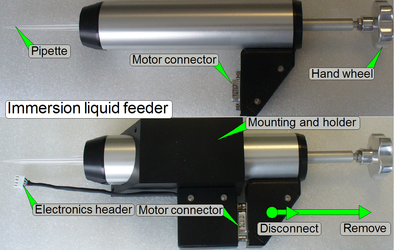 The immersion
objective with 40x magnification requires distilled water as immersion liquid
to produce the image of high quality.
The immersion
objective with 40x magnification requires distilled water as immersion liquid
to produce the image of high quality.
For this purpose, an immersion liquid feeder unit is implemented.
Only the pipette itself is the immersion liquid reservoir and may
contain up to ~5ml distilled water.
The pipette is filled manually and the liquid is spend by the help of a
stepper motor, software controlled, before the scan process of the tissue
starts.
Important
· Please use always only
distilled water for the 40x immersion objective.
· During filling the
pipette avoid contamination of the immersion liquid; dust particles or other
contaminations might arrive into the optical path and might be scanned as
tissue!
· Never scan a
tissue with the 20x no immersion objective if immersion liquid is on the cover
slip!
See also: “Power and control”, “Immersion liquid feeder” and “Image gallery”
1.
 Pull the immersion
liquid feeder unit out of the holder
Pull the immersion
liquid feeder unit out of the holder
·
Disconnect the motor connector first, then remove the
liquid feeder unit as shown.
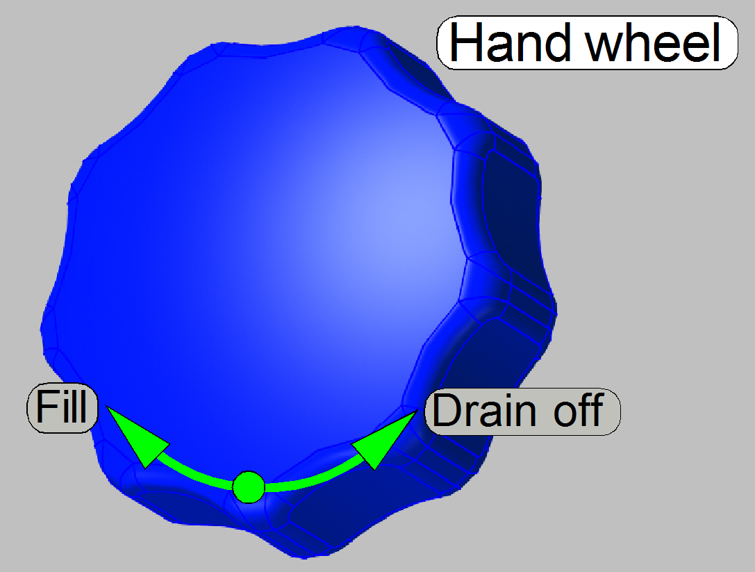
2.
Remove the remaining water of the pipette first, it should
be disposed!
·
By driving the hand wheel to the left, the plunger
will be moved in direction of the pipette tip, the remaining water will be
removed from the pipette.
3.
Clean the pipette tip first (e.g. with alcohol),
before immersing it into the distilled water to be filled in.
·
Immerse the pipette tip into the distilled water and
drive the hand wheel to the right until the pipette is full.
4.
Remove water drops from the pipette and insert the
liquid feeder unit into its holder.
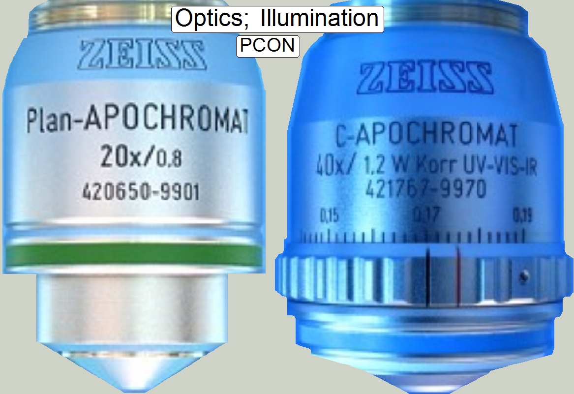
 In
microscopes, the objective gathers the light, emitted from the tissue to be
observed and focuses the rays to produce an image. The character of the
objective is given by the
magnification and the numerical aperture.
In
microscopes, the objective gathers the light, emitted from the tissue to be
observed and focuses the rays to produce an image. The character of the
objective is given by the
magnification and the numerical aperture.
The position of the objective and the distance to the tissue is very
important to produce a sharp image. Because in Pannoramic scanners this
distance can be modified by moving
the tissue position (focusing) both positions, the objective position and the nominal focus position
are important.
·
See also
“Objective changer” to mount the objective
and the objective
position adjustment.
·
See also “Optical path and Field Of View”
See also: Objective; © Objectives_for_Microscopes_from_Carl_Zeiss.pdf;
stored
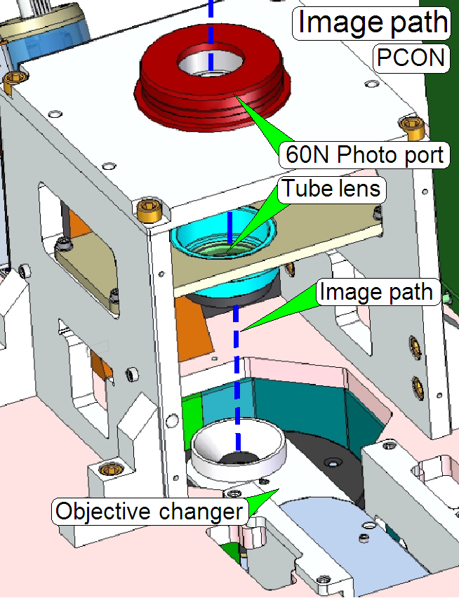
The image path consists of the following units and components
· Tube lens mounting
and holder
· 60N Photo port and
holder
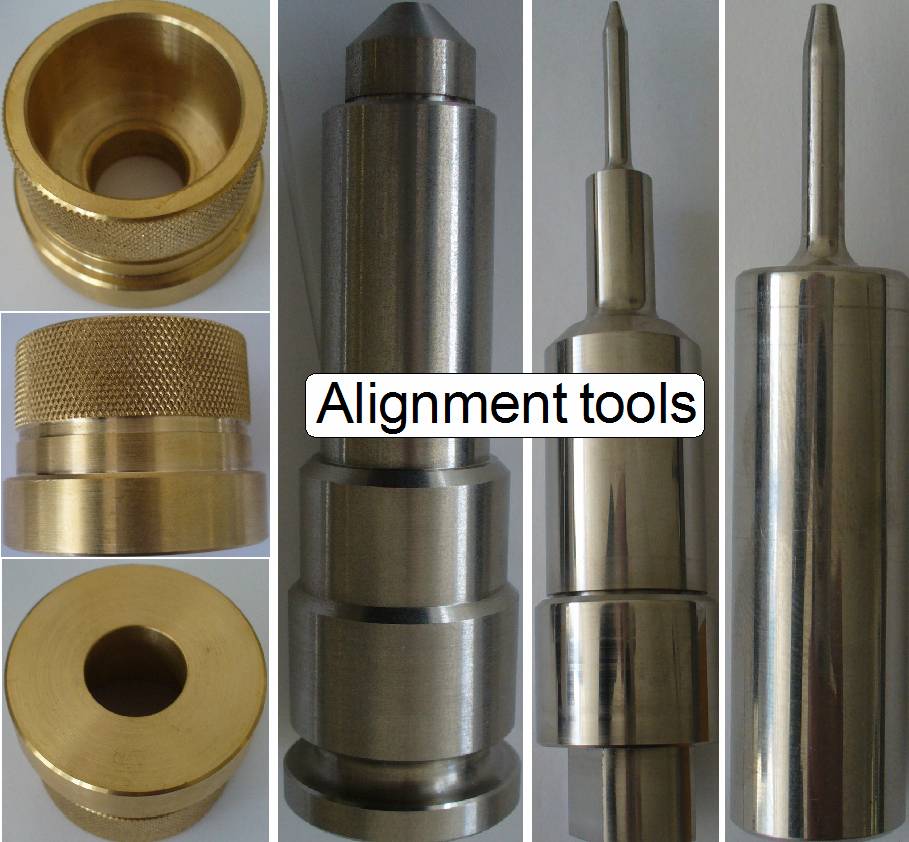
To make the optical axis straight and centered, the image path’s
components and units position is adjusted.
See also: “Image path
adjustment tools” and “adjust the image path”
 The Aurox CC88 is
an imaging unit and influences the image, seen by the objective.
The Aurox CC88 is
an imaging unit and influences the image, seen by the objective.
The principle of confocal imaging is, to create two images of the field
of view, seen by the objective at the same tine.
In one time, the image goes straight and one time reflected; this way,
two image paths are created.
Both images are prepared by optical means and transferred to the scan
camera.
The scan camera with a large image sensor sees both images (the real
image and the reflected image) at the same time; one half of the image sensor
contains the real image, the other half of the sensor contains the reflected
image.
The images delivered by the scan camera with one exposure are separated
by software and the reflected image part will be subtracted from the real image
part. This way, light rays, created by elements out of focus can be eliminated
and the depth of sharpness will be increased.
The Aurox CC88 uses a spinning disk to create the reflected image.
For any kind of non-confocal scan operation, the spinning disk can be
removed from the optical path, software controlled.
Possible operating modes are
· Brightfield
confocal
· Fluorescent
confocal
· Brightfield
non-confocal and
· Fluorescent
non-confocal
Remark
Not all the possible scan modes are realized!
See also: “Confocal unit”
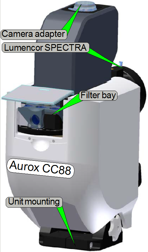
Camera adapter ring
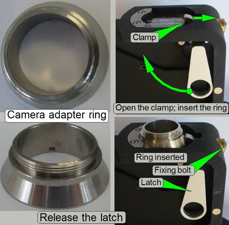 The C-mount camera
adapter ring is situated between the camera and the Aurox CC88 spinning disk
unit.
The C-mount camera
adapter ring is situated between the camera and the Aurox CC88 spinning disk
unit.
· The usable
magnification of the C-mount Camera Adapter Ring is always 1:1!
· Drive the C-mount
Camera Adapter Ring manually first onto the camera until it stops
· Loosen the fixing
bolt
· Move the latch as
shown to open the clamp and insert the C-mount Camera Adapter Ring with camera
· Release the latch
and adjust the camera rotation angle
· Tighten the fixing
bolt
Mount the Aurox CC88 spinning disk unit
· 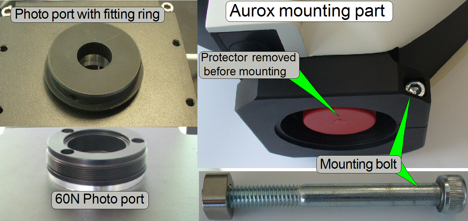 Drive the fitting
ring onto the 60N Photo port manually, until it stops
Drive the fitting
ring onto the 60N Photo port manually, until it stops
· Loosen the
mounting bolt on the Aurox unit a bit.
· Put the Aurox unit
onto the fitting ring and so, that the fluorescent light input shows to the
Lumencor SPECTRA light engine.
· Tighten the
mounting bolt
·
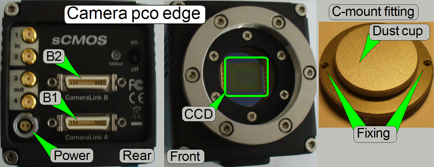 In all scan modes,
the camera PCO.edge with a resolution of 5.5Mp is used until otherwise
specified.
In all scan modes,
the camera PCO.edge with a resolution of 5.5Mp is used until otherwise
specified.
·
The camera produces monochrome, gray scaled images.
· See: Camera “PCO.edge”
· See also: “Adjustment procedures” to “Adjust the camera rotation
angle”
· “CCD versus
CMOS image sensor”.
· What
is the difference between CCD and CMOS image sensors in a digital camera?
· CMOS Image
Sensor Technology
·
Random Access CMOS - Sensoren in der
Bildverarbeitungspraxis
General
Even illumination is important in microscopes and in
all of our scanners as well. A well adjusted illumination ensures that any
approved camera can be used properly with our scanners without further
adjustments.
The entire adjustment procedure of the optical path
can be divided into two main parts,
1. The
FOV illumination adjustment and
2. The
image path adjustment.
The adjustment parts can be done nearly separately
from each other, but always the illumination path is adjusted first and only
then will be adjusted the image path. If the adjustments are done, the entire
result should be checked again!
The adjustment is always done from the light source to
the tissue and from the tissue to the CCD of the camera. Because distances are
not measurable, the actual adjustment result is used to adjust the next
component. This procedure requires adjusting or checking the position of
previously adjusted components again!
Illumination adjustment
 The
goal of the brightfield illumination adjustment is, to illuminate the FOV, seen
by the objective pupil (and the scan camera) evenly and with a density of light
as much as possible.
The
goal of the brightfield illumination adjustment is, to illuminate the FOV, seen
by the objective pupil (and the scan camera) evenly and with a density of light
as much as possible.
The adjustment of the illumination path is reduced to
the adjustment of the objective position and the condenser position.
The successful adjustment of the condenser requires
the nominal focus position; so the focus position of the objective must be
adjusted correctly before we can adjust the condenser position.
- If the FOV is not fully
and evenly illuminated, the quality of the virtual tissue becomes poor,
and
- If the illuminated field is too large, the exposure time of the
camera will increase and the scan procedure slows down, because the light
density is reduced.
· In the PCON, the adjustment of the illumination path is reduced to the
adjustment of the objective position and the adjustment of the condenser
position.
Adjustment
procedure
Measure the thickness without cover slip of the slide
to be used for the objective position adjustment and calculate the number of
focus steps to be set in the focus unit; calculate the focus position; see
also: Check or
adjust the objective position
![]() Adjust
the objective and focus position
Adjust
the objective and focus position
1.
 Start
the scan program “SlideScanner.exe”,
Start
the scan program “SlideScanner.exe”,
2.
Insert a slide with the known focus
position for PCON.
3.
In
the tab “Focus” create a live view and set the focus unit to the known focus
position of the slide.
4.
Now adjust the objective position until
the tissue becomes in focus.
5.
Fix the objective position by tightening
the fixing bolt of the objective nut.
6.
Execute the auto focus command.
7.
The found focus position should not have
more then 50 steps in distance to the known or calculated focus position.
8.
If the deviation is too much, adjust the
objective position more precise.
See also: “Objective changer”; “Dismount or mount
the objective”; “Objective position”; “Check or adjust the objective position”.
![]()
Adjust the condenser position
- Create a live view with the BF scan mode in the tab “Focus”
and adjust the condenser position; use the green light source.
See also: “Adjust condenser position”;
“Condenser”.
The entire image path adjustment includes the
adjustment of the following parts:
1. Objective position
This
adjustment ensures that tissues with different thicknesses can be scanned in
focus; of course, it was adjusted previously for the brightfield illumination,
but the objective position should be checked or adjusted again. If the
objective position is incorrect, the tissue or parts of it can not be scanned
in focus; see also “Check the optical path adjustments”.
2. Photo port and tube lens
position
The
position of the tube lens as well as the position of the 60N photo port affects
the color trueness of the scanned tissue; the chromatic aberration becomes
visible in blue, and red or yellow colored cell borders on the opposite sides.
Because both components are mounted separately, both components have to be
adjusted well; see also “Chromatic aberration”
and “Straightness of the image path”.
3. Camera
rotation angle
If
the camera rotation angle is out of the limits, the stitching is not correct
and the borders of the FOV’s becoming visible in the virtual tissue with the
viewer program, the sample does not fit on the border of the FOV; see also
“Stitching’.
Straightness of
the image path
 The
straightness of the image path is affected by all components, included between
the condenser’s mounting until the sensor of the camera.
The
straightness of the image path is affected by all components, included between
the condenser’s mounting until the sensor of the camera.
The entire adjustment includes:
1.
Straightness of the optical axis between
condenser and objective (objective disc mounting);
see “Align the objective into the
optical axis”
2.
Straightness of the tube lens mounting
position is in relation to the objective mounting;
see: “Align
the tube lens”.
3.
Straightness of the 60N photo port
position is in relation to the tube lens mounting;
see: “Align
the 60N photo port”.
4.
Inclination of the Aurox unit is in
relation to the momentarily defined optical axis (requires software aided
adjustment).
Remark
· Not
finished yet; procedures will be described in future updates
 The
appearance of chromatic aberration can be divided into two main reasons:
The
appearance of chromatic aberration can be divided into two main reasons:
1. The
used materials (the composition of the glass) in the lens system; different
wavelengths of light will be focused to different positions; and
2. The
arrangement of the lenses to each other (centermost), with other words, the
straightness of the optical path (lens system).
- For any kind of aberration see “Optical
aberrations”
Chromatic aberration of a FOV is seen as unevenly
colored cell borders. Because the first item is given by the used optics (the
construction of the objective and the lenses) and can not be affected by the
technician, we minimize the chromatic aberration by making the optical path
straight and centered.
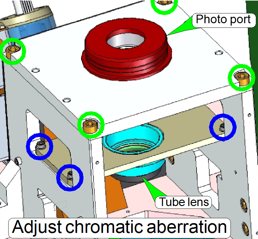
For this purpose, in the PCON the position of the
tube lens and the position of the photo port in relation to the objective
(changer) will be modified (with loosened tube lens and
photo port mounting bolts).
· After
the chromatic aberration adjustment was finished, the camera rotation
angle has to be adjusted (again).
 The
adjustment of the chromatic aberration is done in the real focus position and
in the center of the FOV to be observed.
The
adjustment of the chromatic aberration is done in the real focus position and
in the center of the FOV to be observed.
- A zoom factor of 2,73 is very helpful for this adjustment.
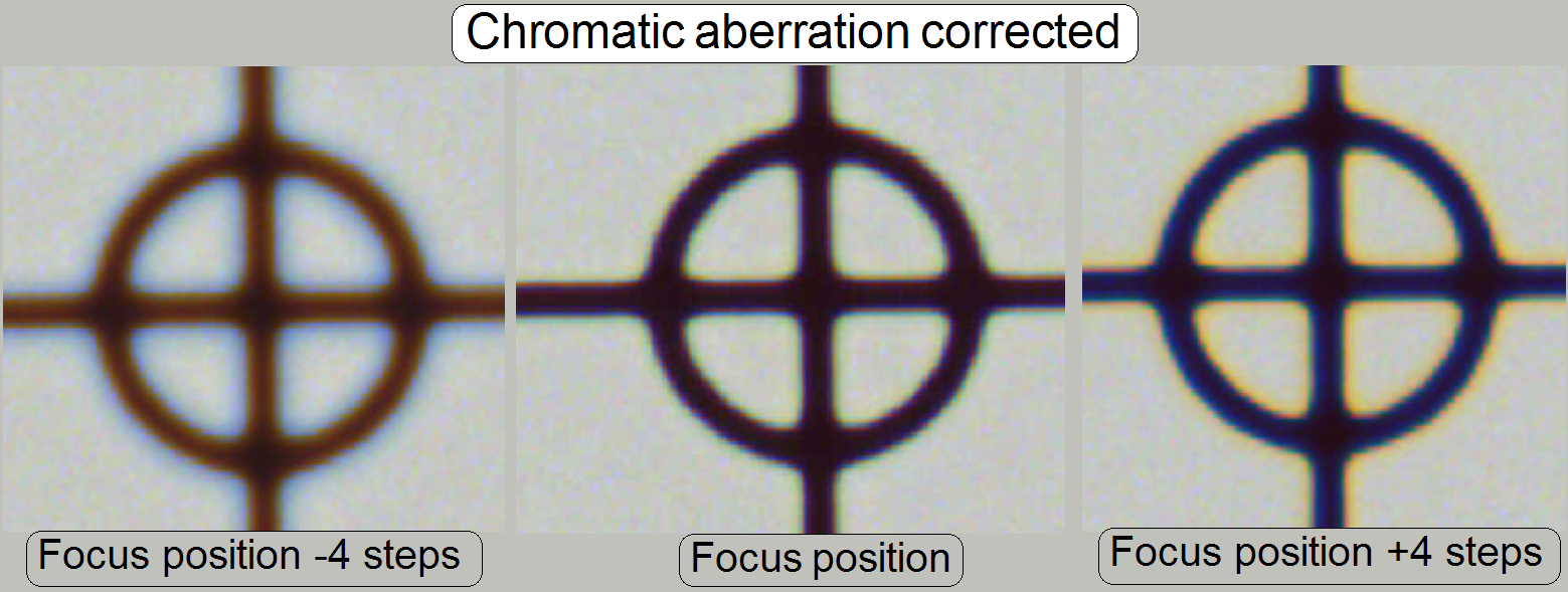
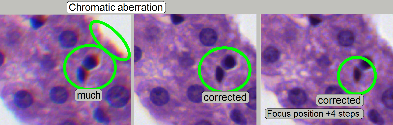
To check the result of the adjustment, the focus
position can be modified by some steps in positive or negative direction. In
this way, the correctness of the adjustment becomes more visible. If the yellow
color occurs evenly on the inner and outer part of the circle in the center,
the adjustment is acceptable; see “Focus position +4 steps”.
 The images are done in the focus position of
the live view, except otherwise specified and with a zoom factor of 2,73.
The images are done in the focus position of
the live view, except otherwise specified and with a zoom factor of 2,73.
Chromatic
aberration becomes visible if the optical light path is not exactly
perpendicular (mirrors) or centered (lenses); it is corrected by different
positioning of the tube. For this purposes use a well visible tissue. To
adjust the chromatic aberration use and observe always the center of the FOV,
never the border, because the border has always more chromatic aberration as
the center!
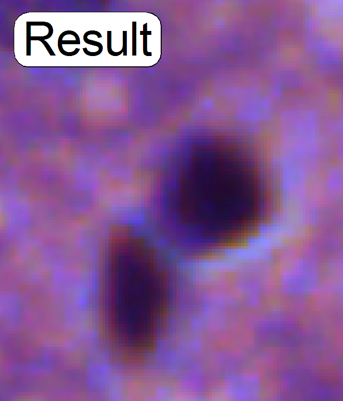
Example: If the otherwise
dark spots in the tissue have red or yellow boundaries on the top, and blue
boundaries on the bottom (see also above “Chromatic aberration”),
move the tube to the red, yellow direction.
1.
Start the program “SlideScanner.exe”, type
in the service password and load a slide with tissue.
·
Important: Check
the proper position of the slide in the specimen holder!
2.
After the preview is done, select the
option “Focus” and click on the button “Live view”, positioning tool ![]() and click inside the tissue and find a
well usable FOV with a lot of cells. Use the “Auto focus” button.
and click inside the tissue and find a
well usable FOV with a lot of cells. Use the “Auto focus” button.
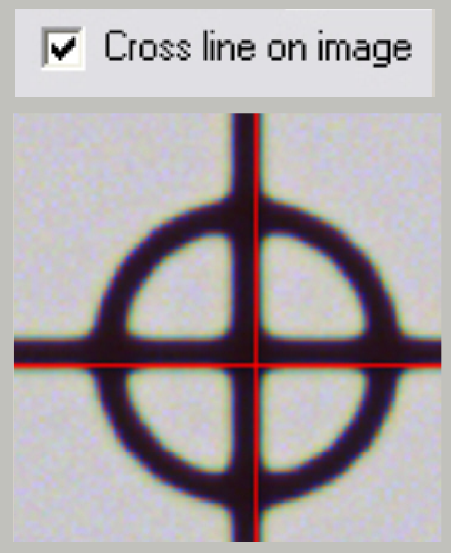
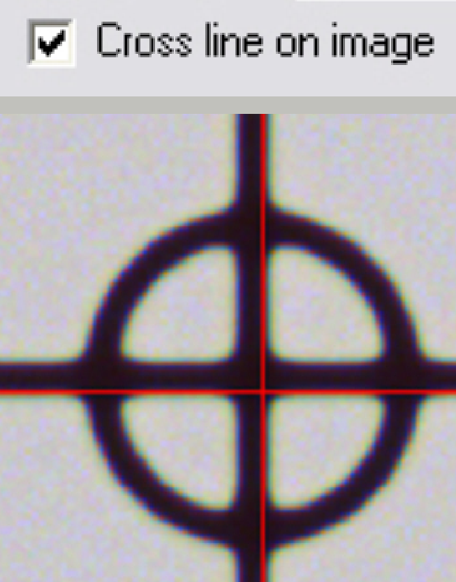
3.
Switch to “Service’ and “Microscope
control”; check the checkbox “Cross line on image”
4.
![]()
![]() Fit the camera
view to the size 1:1 with the button 1:1 and zoom in by using the zoom tool
until a zoom value of 2,73 is reached.
Fit the camera
view to the size 1:1 with the button 1:1 and zoom in by using the zoom tool
until a zoom value of 2,73 is reached.
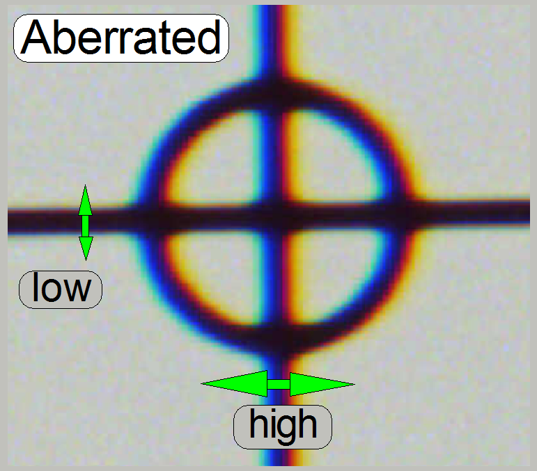
5.
If the zoom value is large enough (between
2.6 and 3), you can see something like this “Aberration”. If yellow, red or
brown colors are visible at the boundaries of spots on only 1 side and the
opposite side is blue, the optical system has chromatic aberration; check this
behavior on different positions of the tissue also.
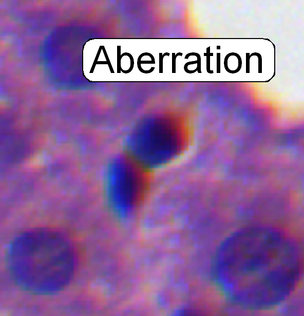
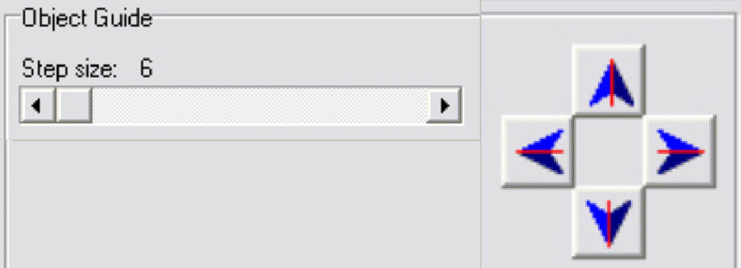
 Move the scroll bars so, that the cross is
visible on the screen. Observe always the center of the field of view; in
the near of the cross. To find the desired positions, set a step size in
the tool “Object guide” and move the stage by using the movement buttons.
Move the scroll bars so, that the cross is
visible on the screen. Observe always the center of the field of view; in
the near of the cross. To find the desired positions, set a step size in
the tool “Object guide” and move the stage by using the movement buttons.
6.
Loosen the tube fixing
bolts until the tube becomes just barely moveable.
7.
Move the camera changer on its mounting in the
direction, where the red or yellow color of the spot or cell occurs; see also “Position of
camera changer unit”.
8.
After pressing the “auto focus” button,
use a focus step size of 2 steps and go from the auto focus position in plus
direction. If the cell gets a brown or yellow ring in nearly constant thickness
the aberration seems to be adjusted.
9.
Repeat step 8 and check this result on
different positions of the same slide (tissue) with live view.
10. 
 Scan a
tissue or a part of it and check the result with the program “SlideViewer”.
When you can find more positions where the aberration is visible always on the
same side of the cells, repeat from step 6.
Scan a
tissue or a part of it and check the result with the program “SlideViewer”.
When you can find more positions where the aberration is visible always on the
same side of the cells, repeat from step 6.
11. When you can find parts of the tissue where
the chromatic aberration is visible on different sides of the spots, the
chromatic aberration seems to be adjusted.
12. Scan
two further tissues with different samples and check the results (repeat the
steps 10, 11).
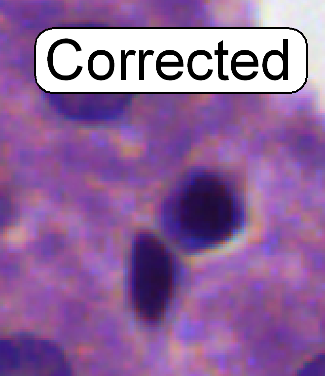
13. If the
boundaries of the spots (see “corrected”) are colored evenly the optical path
is correct.
14. Tighten
the component’s mounting bolts and check the result, by repeating the steps 8
to 11. If necessary, repeat the steps from step 6.
15. After
the chromatic aberration adjustment was finished, the camera rotation
angle has to be adjusted (again).
· Before
scanning tissues the scan program “SlideScanner.exe” has to be restarted,
otherwise stitching errors might occur.
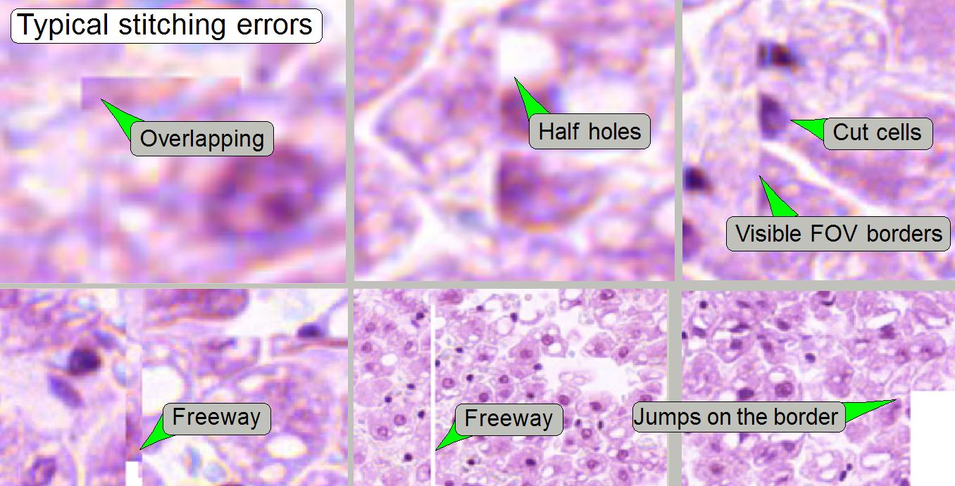 Stitching
errors have two main reasons:
Stitching
errors have two main reasons:
1. Improper adjusted camera rotation angle
and
2. The
hysteresis in Y-direction is too much.
The camera angle becomes important during stitching.
If the angle of the scan camera is out of the limit, the stitching does not
working well, so the FOV’s, seen with the viewer does not fit to each other. An
acceptable camera angle has less than +-0.5 degrees deviation from zero.
If the camera angle is correct and stitching errors
occurs, check the hysteresis in Y-direction.
- See the next chapter “Y- and
X-hysteresis” and “X-Y-stage unit”
Adjust the camera
rotation angle
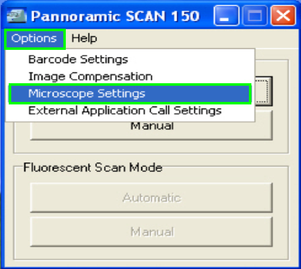
In the selector menu
and ‘Options” start the item “Microscope settings”.
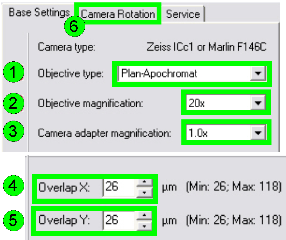
In the tab “Base settings” set the values for the
parameters numbered with (1)-(5) as these are true for the scanner to be set
up; then change to the tab “Camera rotation” (6).
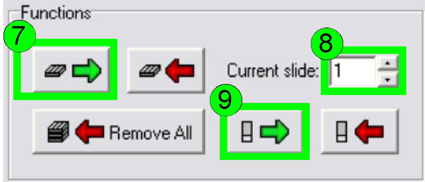 Load a
magazine (7), select the desired slide position (8) and insert the slide
(9).
Load a
magazine (7), select the desired slide position (8) and insert the slide
(9).
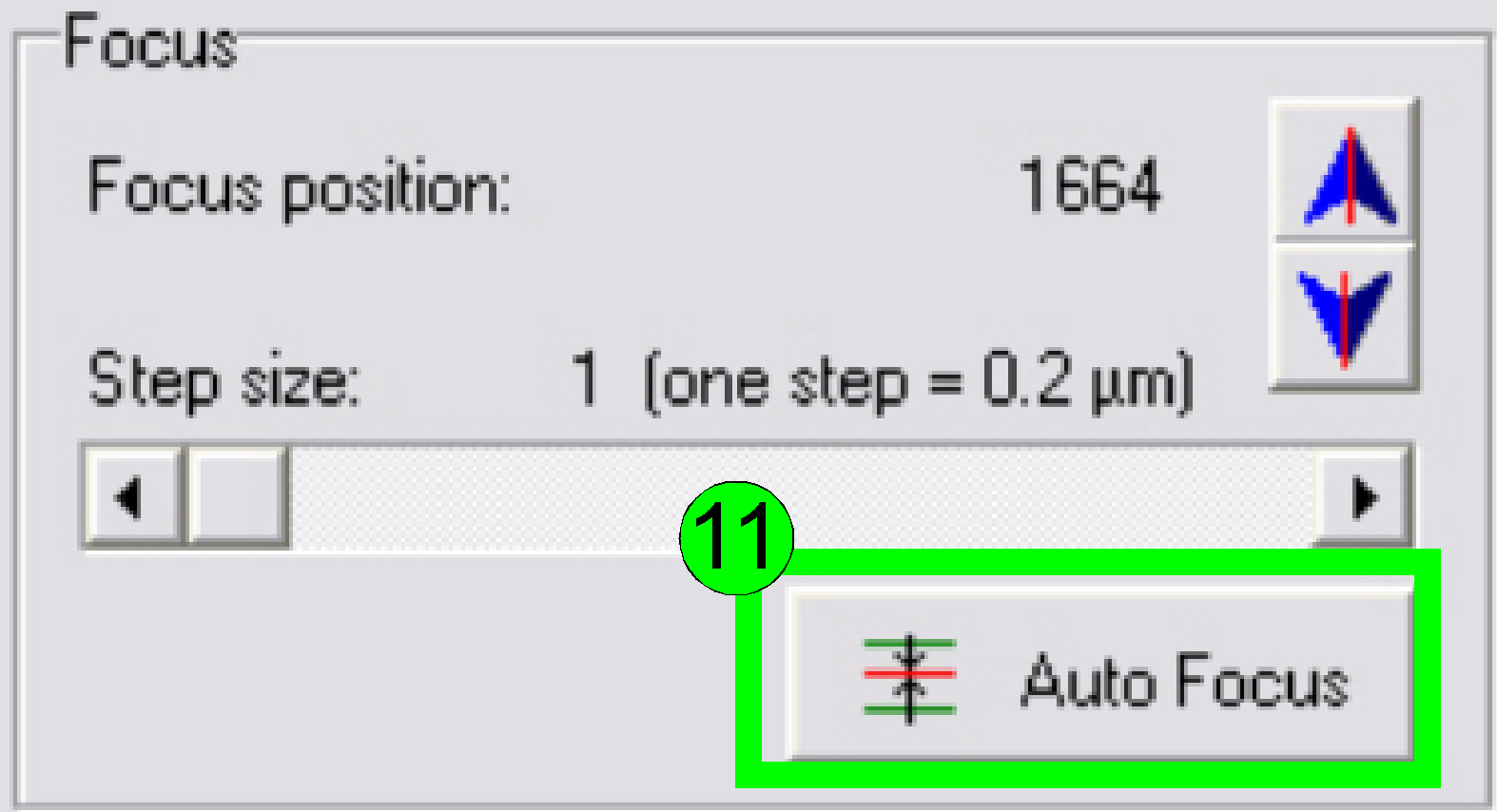
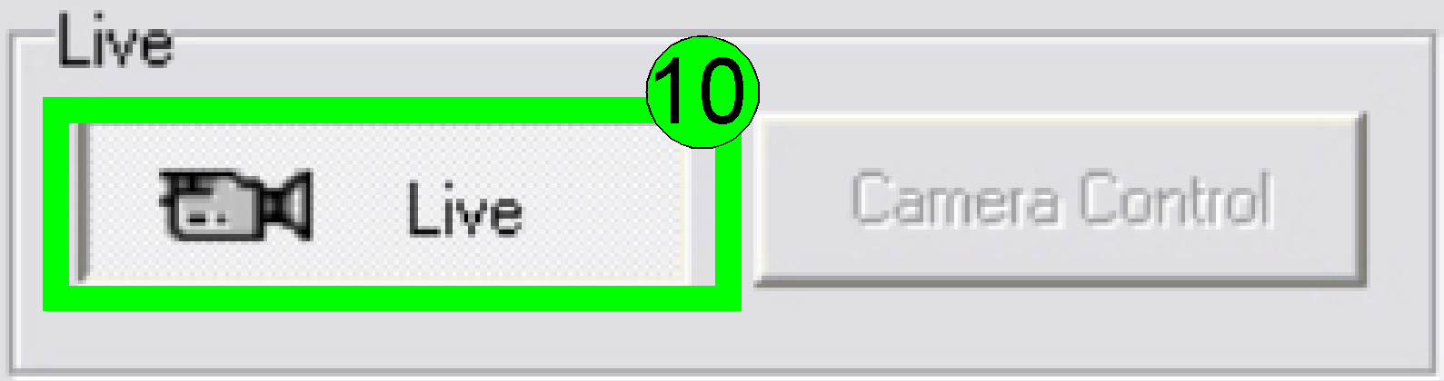 In the
preview window find a FOV with tissue; press the button “Live view” (10) and “Auto
focus” (11). If the focus position is found, click outside the tissue and
inside the cover slip on a “white” position.
In the
preview window find a FOV with tissue; press the button “Live view” (10) and “Auto
focus” (11). If the focus position is found, click outside the tissue and
inside the cover slip on a “white” position.
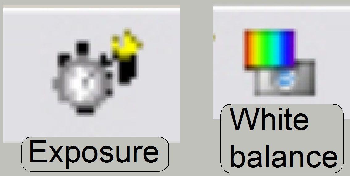 Set
the “Auto exposure time” and the “White balance” by clicking on the appropriate
icon on the lower screen border.
Set
the “Auto exposure time” and the “White balance” by clicking on the appropriate
icon on the lower screen border.
Click inside the tissue and find a well usable FOV
with cells.
Find the focus position (11).
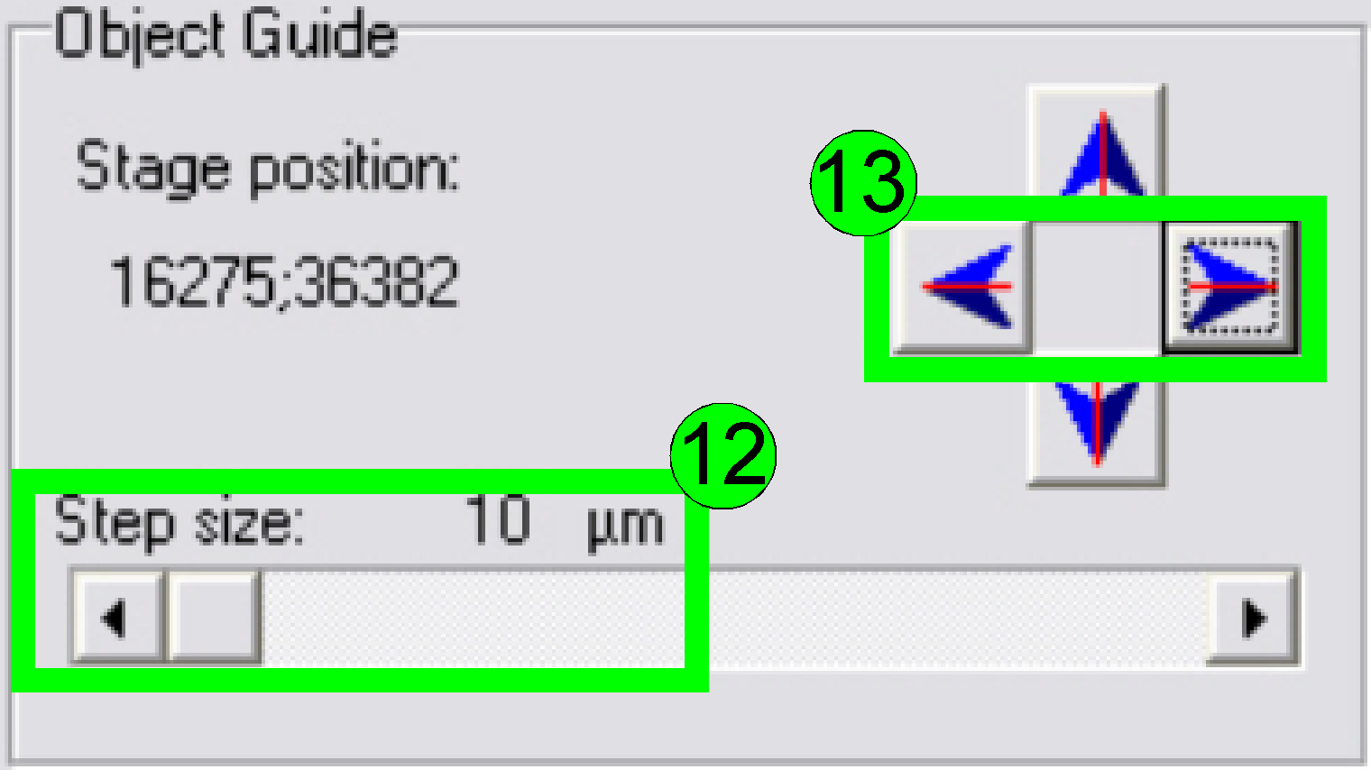 Select
a “Step size” of 10 or 20 µm (12) and move the object guide to the left or
to the right as desired (13) and observe the movement of a cell near to or on
the horizontal red line. If the cell deviates from the red (horizontal) line in
the center upward or downward respectively, correct the camera angle
continuously (by moving the camera adapter on its mounting) until the cell
moves on the red line (14) or exact parallel to it.
Select
a “Step size” of 10 or 20 µm (12) and move the object guide to the left or
to the right as desired (13) and observe the movement of a cell near to or on
the horizontal red line. If the cell deviates from the red (horizontal) line in
the center upward or downward respectively, correct the camera angle
continuously (by moving the camera adapter on its mounting) until the cell
moves on the red line (14) or exact parallel to it.
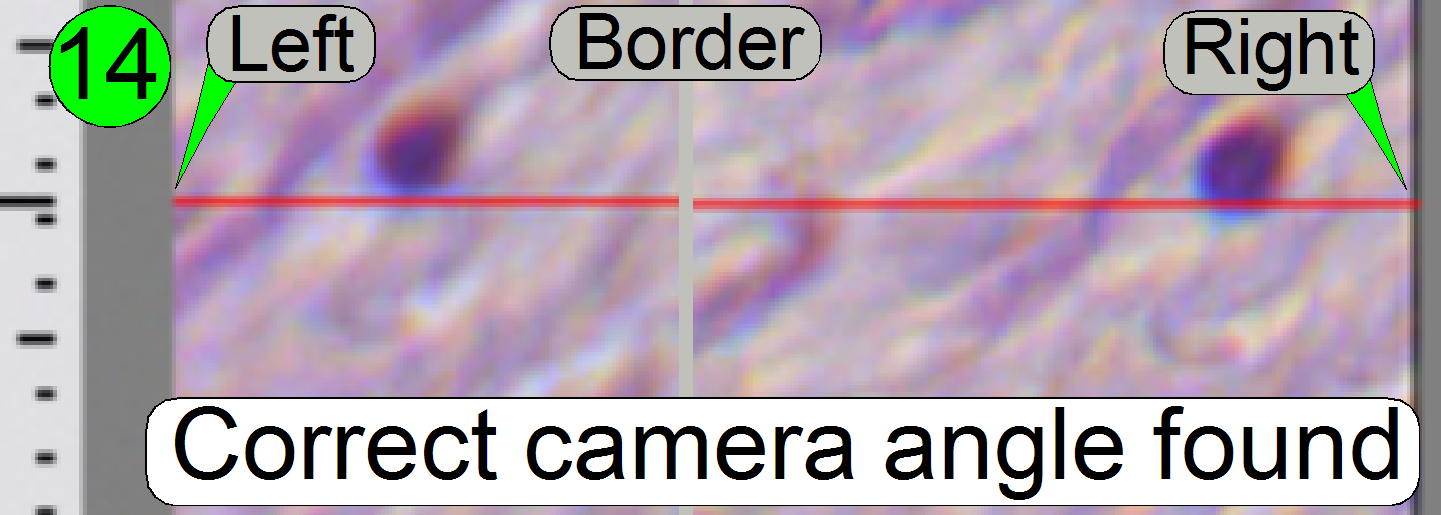 If the
cell moves from the left border to the right border of the screen (or reverse)
nearly on the red line, the camera angle is correct (14).
If the
cell moves from the left border to the right border of the screen (or reverse)
nearly on the red line, the camera angle is correct (14).
 Press the button “Measure Camera Rotation”
(15).
Press the button “Measure Camera Rotation”
(15).
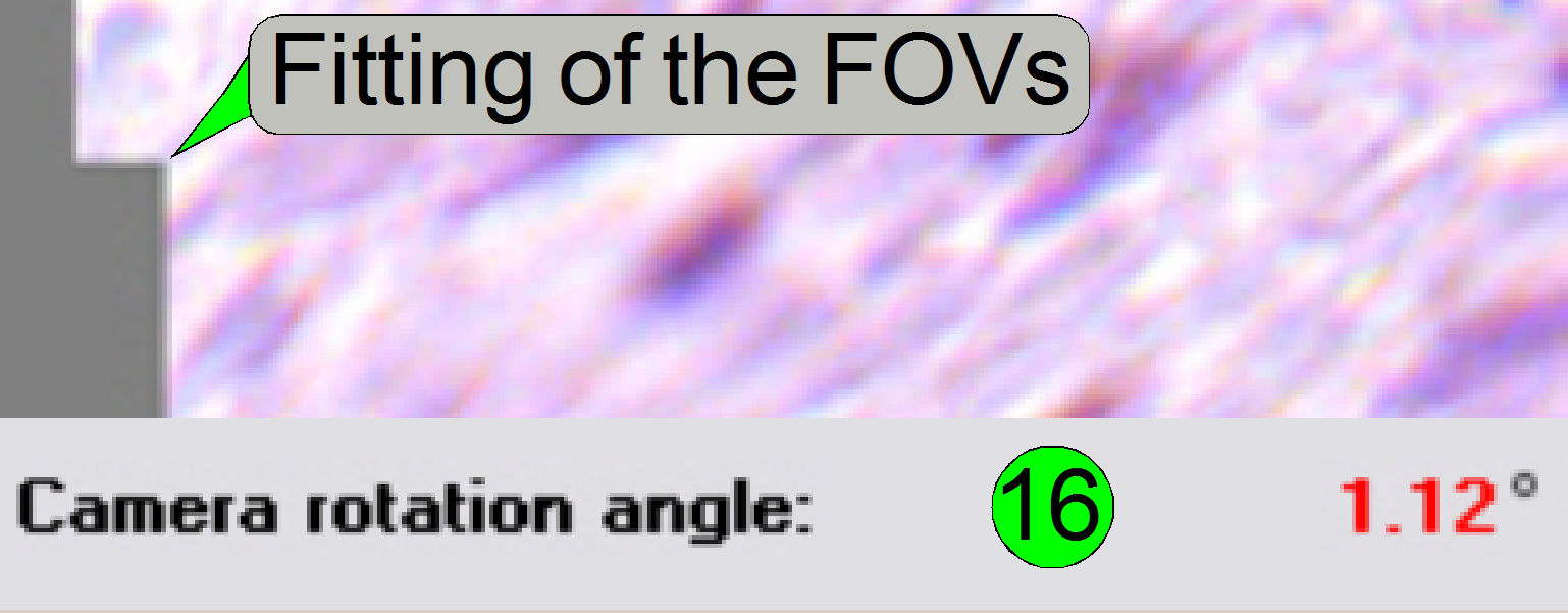 Now
the program arranges two FOVs to each other and shows so graphically the
fitting of the FOVs in the centre of the live view; the numerical value of
deviation is shown in the lower part of the left sided adjustment window. If
the value of the rotation angle is shown in red, the position must be adjusted
more precise (16). Correct the camera position and press the button “Measure
Camera Rotation” (15) again, until an acceptable angle is found.
Now
the program arranges two FOVs to each other and shows so graphically the
fitting of the FOVs in the centre of the live view; the numerical value of
deviation is shown in the lower part of the left sided adjustment window. If
the value of the rotation angle is shown in red, the position must be adjusted
more precise (16). Correct the camera position and press the button “Measure
Camera Rotation” (15) again, until an acceptable angle is found.
 If the
rotation angle can be accepted, the angle value is shown in black (17); an
acceptable value has less then 0.5degrees in deviation.
If the
rotation angle can be accepted, the angle value is shown in black (17); an
acceptable value has less then 0.5degrees in deviation.
 Save
the calculated rotation angle to the appropriate file by pressing “Save” (18);
and in the next following dialog answer with “YES” to save the file.
Save
the calculated rotation angle to the appropriate file by pressing “Save” (18);
and in the next following dialog answer with “YES” to save the file.
Leave the menu “Options” by clicking on “Exit”.
Check the optical path adjustments
As discussed previously, the correct objective and focus position is
important to be able to scan tissues of different thicknesses in focus.
This fact we are using to determine the correct
objective position.
1. Find at
least three, better are 5 slides with tissue of different thickness and of
different kind.
2. Insert
the (next) slide; check the correct position of the slide in the specimen
holder!
3. Produce
a live view of the tissue, press “Autofocus” and notify the focus position.
4. Repeat
step 3 on 5 different positions of this tissue; the distance of the positions
should be as much as possible.
5. Calculate
the average focus position of this slide and notify it.
6. Repeat
from step 2 until the average focus position of all the selected tissues is
determined.
7. Calculate
the average focus position of all the tissues.
8. If the
average focus position deviates more then 50 steps from the nominal focus
position, calculated with the used slide thickness, the objective position
should be corrected.
9.
If the objective position was modified,
please check the correctness of the condenser position again.
 Check
the correct condenser position in the focus positions -300, 500 and 1300 steps.
There must not be significant differences.
Check
the correct condenser position in the focus positions -300, 500 and 1300 steps.
There must not be significant differences.
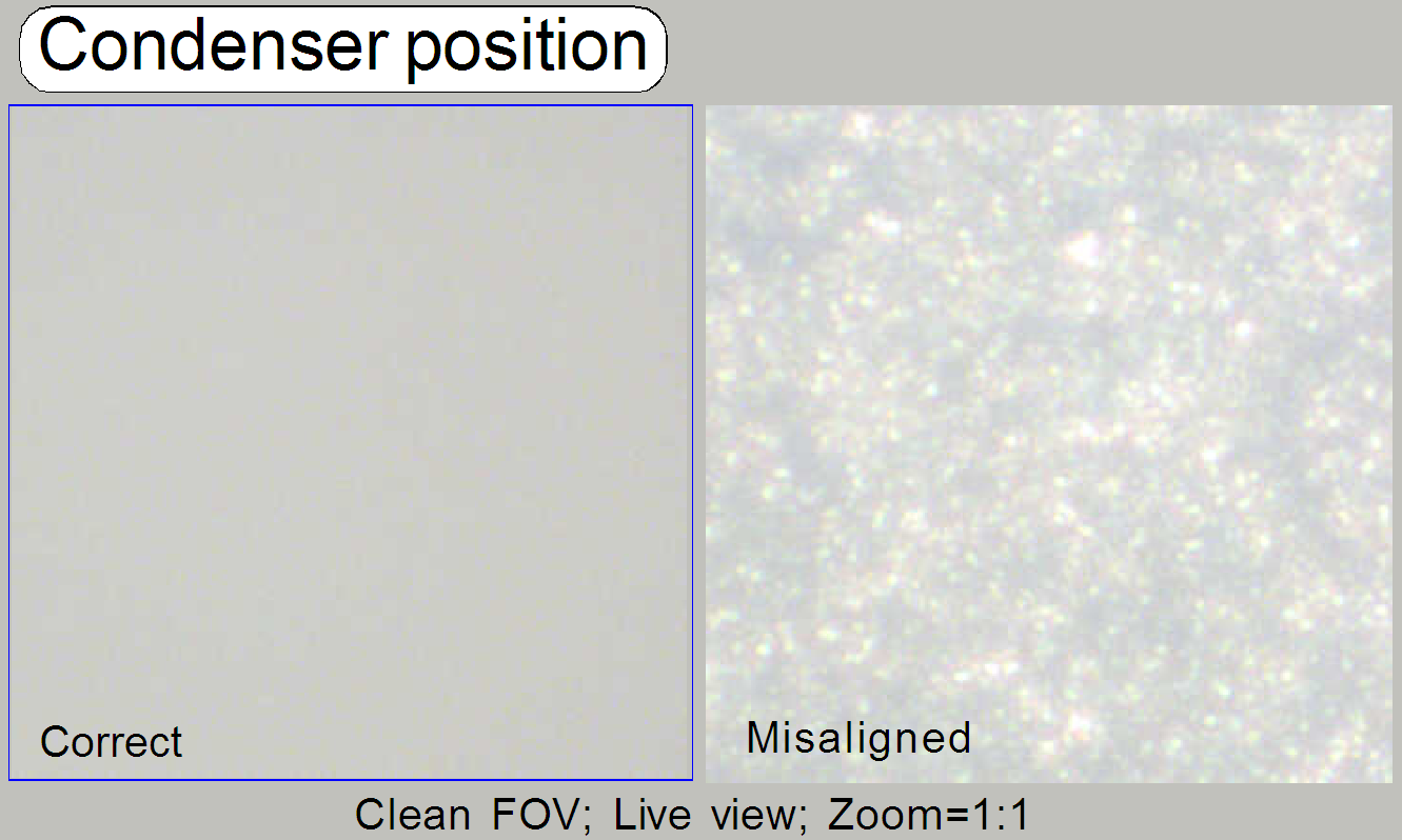
· For
best scan results, the clean FOV should be evenly illuminated over the entire
focus range.
· If the
condenser is misaligned, the roughly surface of the diffuser becomes visible!
Remark
“Clean FOV” means a Field of View, seen by the scan
camera without tissue, dust or dirt, between slide and cover slip.
See also: “Adjust the condenser
position” and “Focus unit”
General
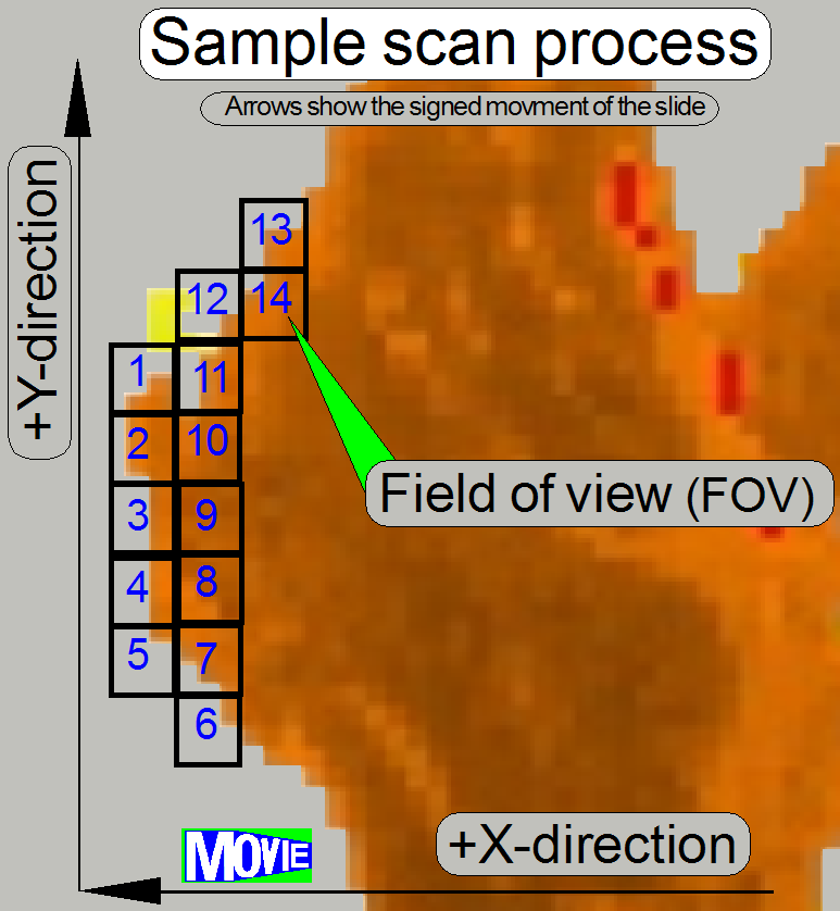 The software divides the sample to
be scanned, seen by the preview camera into fields
of views; the size of the FOV depends on the resolution and the size of the scan
camera’s CCD and the magnification of the camera adapter. Each field of view
contains a small part of the neighbor FOV. In this way, stitching becomes
possible. Because the capturing of the FOV’s is done on a meandering course,
the Y-direction is often changed. If the hysteresis in Y-direction is too much,
stitching will not work correctly; therefore, we have to check the hysteresis
in Y-direction. The maximal allowed hysteresis is 4 μm (=4 motor
steps). We comment that this hysteresis decreases itself by some motor steps
after some sample scan procedures, even if the X-Y-stage is brand new.
The software divides the sample to
be scanned, seen by the preview camera into fields
of views; the size of the FOV depends on the resolution and the size of the scan
camera’s CCD and the magnification of the camera adapter. Each field of view
contains a small part of the neighbor FOV. In this way, stitching becomes
possible. Because the capturing of the FOV’s is done on a meandering course,
the Y-direction is often changed. If the hysteresis in Y-direction is too much,
stitching will not work correctly; therefore, we have to check the hysteresis
in Y-direction. The maximal allowed hysteresis is 4 μm (=4 motor
steps). We comment that this hysteresis decreases itself by some motor steps
after some sample scan procedures, even if the X-Y-stage is brand new.
Because the X-direction is never changed during a
sample scan process, the X-hysteresis is not critical and can be some steps
more (max: 8 steps).
· To
reduce the Y-hysteresis, see also “X-Y-stage
unit” and “X-
and Y-carriage drive unit”.
Check the maximal hysteresis in
Y-direction
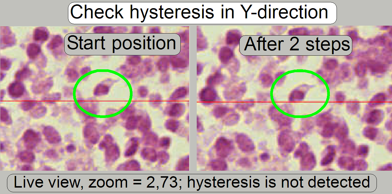 Start
the program “SlideScanner.exe” with the service password. In the tab “Focus”
produce a sharp life view.
Start
the program “SlideScanner.exe” with the service password. In the tab “Focus”
produce a sharp life view.
In the tab “Service” select “Microscope control”. In the
part of the X-Y-control select a step size of two steps and go upward, until
the tissue moves.
Now go in opposite direction and count the clicks
until the tissue moves again. If more then 3 clicks are required, the
hysteresis is too much.
The correction of the hysteresis is difficult to do
and should not be performed in the field.
· See
also “X-Y-stage unit” and “X- and Y-carriage
drive unit”
· Further
information: “How to exchange the
Y-drive unit”
Scan a tissue and check the chromatic aberration with
the Slide Viewer program.
· See also
the chapter above “Chromatic
aberration”.
Scan a tissue and check the stitching with the Slide
Viewer program for stitching errors. See also “Typical stitching
errors” in the description above.
 The
stage skew check is used to determine the inclination of the specimen holder and
so the inclination of the slide. If the inclination is too much, parts of the
tissue are in focus during other parts of the same FOV are not in focus.
The
stage skew check is used to determine the inclination of the specimen holder and
so the inclination of the slide. If the inclination is too much, parts of the
tissue are in focus during other parts of the same FOV are not in focus.
The Stage skew check should be done:
- If the parallelogram was removed.
- If the parallelogram or the specimen holder was exchanged.
- If the entire X-Y-stage unit was changed.
- If the Focus unit was exchanged.
- If any spare part was changed and this spare part is in connection
with the perpendicularity of the optical axis to the slide.
- If the mounting bolt positions or the adjustment bolts position of
the parallelogram was altered.
- See also “Parallelogram
adjustment”.
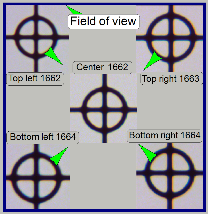
To check the inclination angle of the specimen holder,
a series of screen shoots is done of a cell (circle) in the center of the FOV
and in the upper or lower and left or right corners respectively.
There are 7 screenshots taken in each position; 3
before the found auto focus position and 3 screenshots after the auto focus position.
Then find the screenshot of each position where the cell (circle) is most in
focus. If there is a difference, more then 2 focus steps to the found focus
positions, the specimen holder is slanted and has to be adjusted; this
adjustment can not be done in the field; probably the specimen holder or the
parallelogram is deformed.
Important: Always check the
proper position of the slide in the specimen holder first.
See also the “X-Y-stage
unit”.
In the example on the right the most difference is 2
steps and therefore the inclination of the specimen holder is acceptable.
1.
Start the program SlideScanner.exe with
the service password, insert the slide with circle, produce a live view and
press auto focus.
·
Important: Always check the proper position of the slide in
the specimen holder.
2. Find
the circle and bring it nearly into the center of the live view, press auto
focus.
3. Select
the tab “Service” and “Microscope control”.
4. Select
a step rate about 5 or 10 steps for the object guide.
 5. Check
the checkbox “Cross line on image” and with the object guide movement buttons
bring the center of the circle to the center of the cross; the circle is now in
the center of the FOV.
5. Check
the checkbox “Cross line on image” and with the object guide movement buttons
bring the center of the circle to the center of the cross; the circle is now in
the center of the FOV.
6. Uncheck
the checkbox “Cross line on image”
7. Zoom
in until a value of 2,73 is reached.
8. Grab
the center of the circle (FOV) into the middle of the screen.
9. Memorize
the auto focus position and go backward with the focus position about 20 steps;
and then go forward to the auto focus position -3 steps with a step size by 1.
This way, the probably hysteresis of the focus unit and other mechanics is
eliminated.
10. Make a screenshot
and create a directory named “Focus stack”, name the file as C (for center) and
the number of the actual focus steps, e.g. “C 1659” if the
memorized focus position was 1662 steps and save the file into the directory
“Focus stack”.
11. Increment the
focus position by 1, make the next screenshot and save the file.
12. Repeat step 11
until all the 7 screenshots are done.
13. Now move the
circle with the object guide positioning buttons to a corner position, e.g. to
the upper left corner. The corner is found correctly if the circle can not be
grabbed in direction to the center (see also the green arrows in the image
above “The field of view”).
14. Repeat the steps
from step 9 logically until the screenshots are done in all four corners. The
file names should be UL xxxx, LL xxxx, LR xxxx and
Find the screenshot with the circle most in focus for
each series and notify the file names.
Decide the specimen holder has either to be adjusted or
not as shown in the image above “The field of view”).