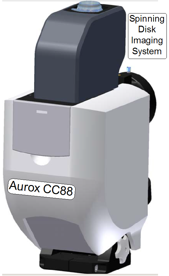
AUROX CC88
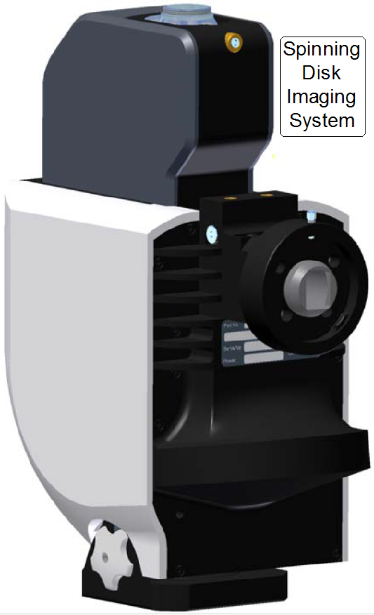
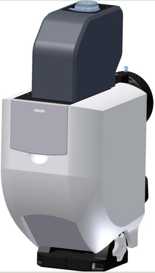
Spinning Disk Imaging System
For
technicians and partly for sales managers!
 These instructions describe the procedures to install and
to use the imaging system Aurox CC88 in the scanner Pannoramic Confocal. To help to resolve problems
with the unit or problems during confocal scanning, working principles, a
functional overview and hardware descriptions of used components are added.
These instructions describe the procedures to install and
to use the imaging system Aurox CC88 in the scanner Pannoramic Confocal. To help to resolve problems
with the unit or problems during confocal scanning, working principles, a
functional overview and hardware descriptions of used components are added.
The following description is based on the Software
version 1.19 and the slide scanner “Pannoramic Confocal”.
 Precautions: Never look directly into the beam of the fluorescent
light source! The lamp emits also ultraviolet light with very high intensity. To
prevent your eyes from harm (damage) use always sun glasses with a high filter
factor of UV light if the fluorescent light source is switched on and you are
adjusting the beam even if the cover of the unit is removed. For further
precautions please, refer to the manual for the fluorescent light source you
are using!
Precautions: Never look directly into the beam of the fluorescent
light source! The lamp emits also ultraviolet light with very high intensity. To
prevent your eyes from harm (damage) use always sun glasses with a high filter
factor of UV light if the fluorescent light source is switched on and you are
adjusting the beam even if the cover of the unit is removed. For further
precautions please, refer to the manual for the fluorescent light source you
are using!
Contents
The exchange of the entire Aurox CC88 Spinning
Disk Imaging System is
possible, if:

- the
shape of any part is deformed or a part is broken.
- the unit has any fault and you are unable to fix it.
- Please contact first our service and support center before any
mountings will be loosened!
Requirements
·
Service
program for Pannoramic
scanners (SlideScanner Service.exe ver. 1.19 or higher) with actual license
file
·
Pannoramic SCAN and Pannoramic Viewer
software (SlideScanner.exe, ver. 1.19
or higher SlideViewer.exe)
with dongle or actual license file
·
1.5, 2.5, 3 and 5 mm hex key wrenches,
·
Hardware
and construction knowledge of the Pannoramic Confocal.
·
Deeper knowledge of handling the Pannoramic
Scan and Pannoramic
VIEWER software
 The Aurox CC88 Spinning Disk Imaging System is a component added to the scanner Pannoramic Confocal to give
the possibility for fluorescent excitation and scanning of tissues in confocal
mode; components of the unit are bypassed internally if non-confocal scan modes
are selected. For fluorescent scanning of tissues, light wave length filters
are used; the filters are assembled into a filter cube. The filter wheel in the
spinning disk system has four positions, so it can contain up to 4 filter cubes
for confocal and non-confocal fluorescent scan sessions of stained tissues.
The Aurox CC88 Spinning Disk Imaging System is a component added to the scanner Pannoramic Confocal to give
the possibility for fluorescent excitation and scanning of tissues in confocal
mode; components of the unit are bypassed internally if non-confocal scan modes
are selected. For fluorescent scanning of tissues, light wave length filters
are used; the filters are assembled into a filter cube. The filter wheel in the
spinning disk system has four positions, so it can contain up to 4 filter cubes
for confocal and non-confocal fluorescent scan sessions of stained tissues.
The spinning aperture disk is used to reject light
rays out of focus and so the contour of the scanned element remains visible.
Important
 In brightfield scan modes the used position of the filter
wheel has to be left blank, without a filter cube inserted!
In brightfield scan modes the used position of the filter
wheel has to be left blank, without a filter cube inserted!
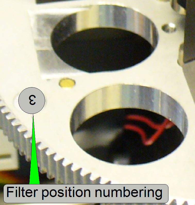
The filter
positions (or inserted filters) can be selected
by software during the fluorescent scan procedure; the assigned filter(s) and
wavelengths will be selected automatically during the automatic scan procedure.
Scanning modes
The imaging system allows the following scan
procedures
· Brightfield
scan non-confocal
· Fluorescent
scan non-confocal
· Brightfield
scan confocal
· Fluorescent
scan confocal
· The
resolution of each confocal scan mode may be 3.3, 5 or 10 line pair / mm
(lp/mm).
Remark
Not all possible scan modes make sense and
therefore, not all modes are realized!
Realized
scan modes
· Brightfield
scan non-confocal
· Fluorescent
scan non-confocal (widefield)
· Fluorescent
scan confocal
Each scan mode may be used in manual scan sessions or
in automatic scan sessions
Configure
the Aurox CC88
Since the software version 1.15
the units of the microscope are configured in the file
“MicroscopeConfiguration.ini”, section [Microscope].
· The USB port
address of the CC88 will be found automatically by the scan program and the
service program; it must not be defined explicitly!
·  The path of the file MicroscopeConfiguration.ini, in the
software version with the operating system Windows® 7 is:
The path of the file MicroscopeConfiguration.ini, in the
software version with the operating system Windows® 7 is:
C:\ProgramData\3DHISTECH\SlideScanner\MicroscopeConfiguration.ini
[Microscope]
SerialNumber=PCON_xxx
MicroscopeType=3DMic10
MicroscopeSubtype=Confocal
ScanCameraType=
PreviewCameraType=CVrmc_m8_pPro
BarcodeReaderType=PreviewCamera
LoaderType=SL_1Mag_12Slide_Sensor_Horizontal2
CameraChangerType=CC_none
ReflectorTurretType=RT_None
BrightfieldLightSourceType=RGBLedLight
ObjectiveChangerType=OC_2Pos
ObjectGuideXYZType=OGXYZ_FLASH4
FlashUnitType=NoFlashUnit
NDFilterType=NDType_None
PreviewLightType=PreviewLightUnitType_Type2
ShutterMotorType=Shutter_Motor
PowerSwitchBoardType=PowerSwitchBoard_Type1
ConfocalUnitType=ConfocalUnitType_Aurox
WaterFeederType=WaterFeeder_Type1
· If
modifications are done in the file “MicroscopeConfiguration.ini”, the scan
software “SlideScanner.exe” has to be started again; only so the modifications
take effect (this is true for some parts of the service program also).
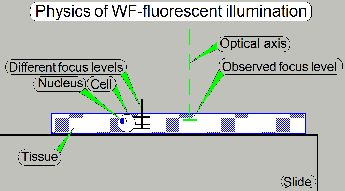 Because the tissue has a thickness and by exciting the
field of view, the excitation light will influence all the tissue parts,
stained with the same stain in more focus levels. This way unwanted out of
focus glare will occur in the observed FOV (emitted from the stain in out of
focus levels) and this “stray light” will blur the element contour.
Because the tissue has a thickness and by exciting the
field of view, the excitation light will influence all the tissue parts,
stained with the same stain in more focus levels. This way unwanted out of
focus glare will occur in the observed FOV (emitted from the stain in out of
focus levels) and this “stray light” will blur the element contour.
![]() “Introduction
to fluorescence microscopy” Nikon MicroscopyU
“Introduction
to fluorescence microscopy” Nikon MicroscopyU
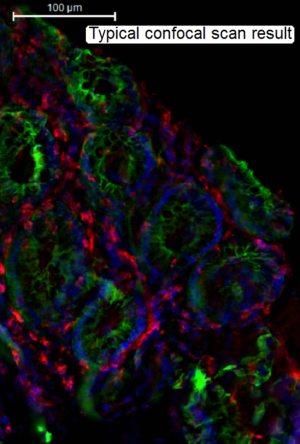
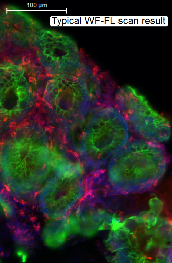
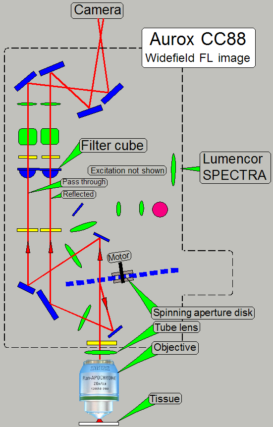
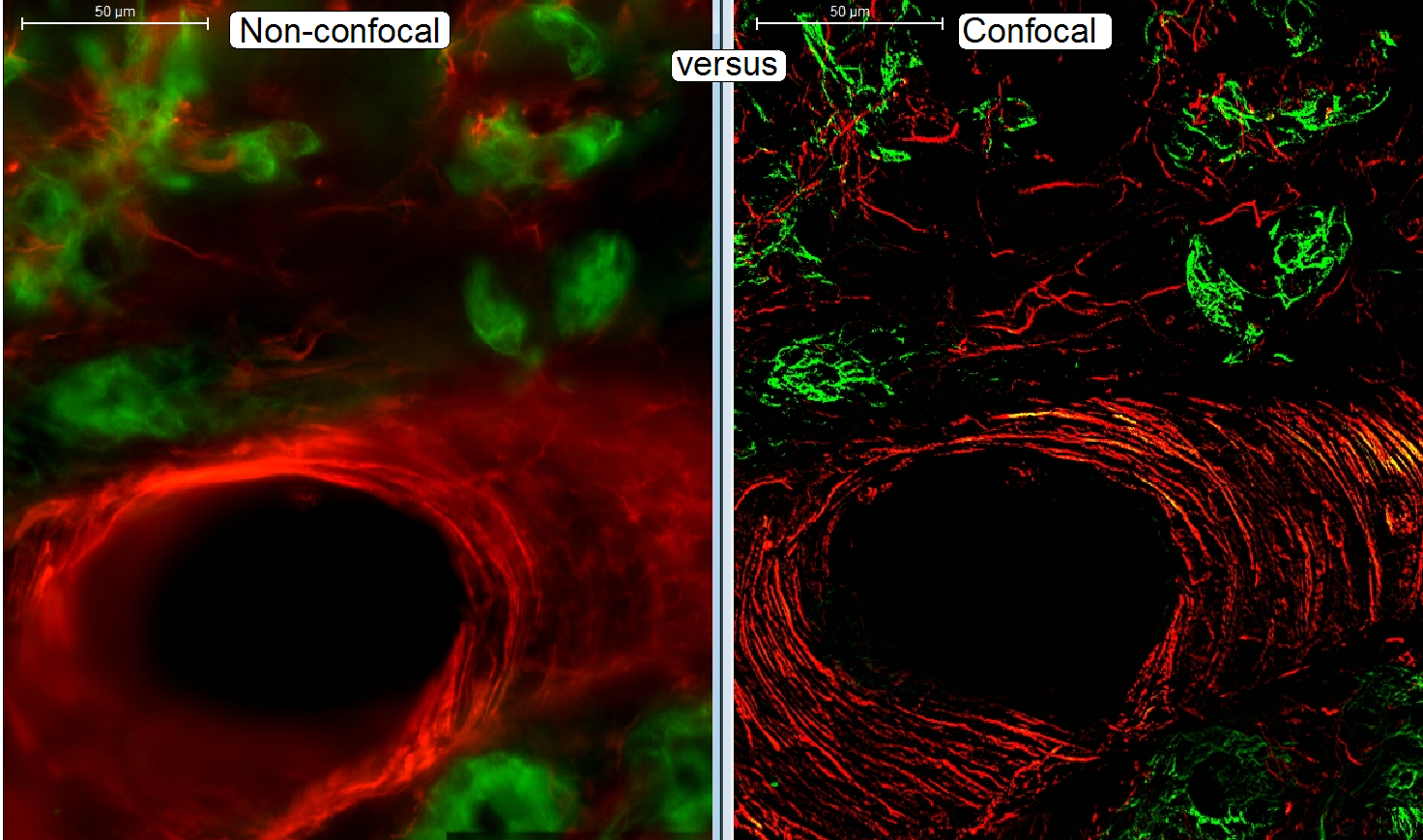
The widefield-FL scanned tissue contains fluorescent flare,
created by emitted light out of focus.
The “blurry” image is disadvantageous, if a
3-dimensional construction of a tissue should be performed and / or the image
should be quantitatively analyzed.
· To
eliminate the emitted light out of focus, the confocal scan mode helps.
 In non-confocal scanning modes (1)
· The
“stray light”, created by excited parts of the tissue out of focus will diffuse
the contour of the element!
First, we should keep in mind, that the confocal scan
principle is designed to reject out of focus light rays.
The tissue
creation process has not changed, in relation to traditional scan modes.
Tissues, previously created for widefield FL mode can also be scanned in
confocal FL mode. The excitation principle is also the same.
The only difference is realized in the image path.
· By
using a grid in the image path, created by the spinning aperture disk a slice
of the tissue in the observed focus level is extracted and so, the light rays,
created by excited parts outside the observed focus level are eliminated.
· In
confocal scanning modes (2) the light rays out of focus are rejected, the
contour of the element remains visible.
 “Confocal
microscopy” Wikipedia
“Confocal
microscopy” Wikipedia
Confocal
Microscopy > Basic
Concepts Nikon MicroscopyU
Confocal Microscopy History and basics; pdf-file, stored
 The main part of the CC88 is the spinning disk system.
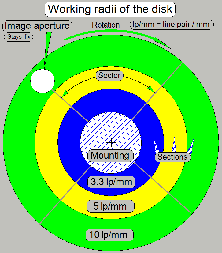
The aperture disk rotates with a speed of 3000rpm and
is inclined in relation to the optical axis, defined by the objective.
The disk itself contains a slit mask and, as the
radius of the disk increases, different resolutions of the slit mask are
realized in tracks.
Three useable sections, arranged as concentrically
tracks are available and so, 3 resolutions are defined.
· In
practice, the construction of the disk is a bit more complicated!
· By shifting
the appropriate section of the disk into the optical axis (image aperture) the
desired grid resolution can be selected.
· If
brightfield scan mode is selected, the disk will be fully removed from the
optical path.
Disk grid design and
resolution
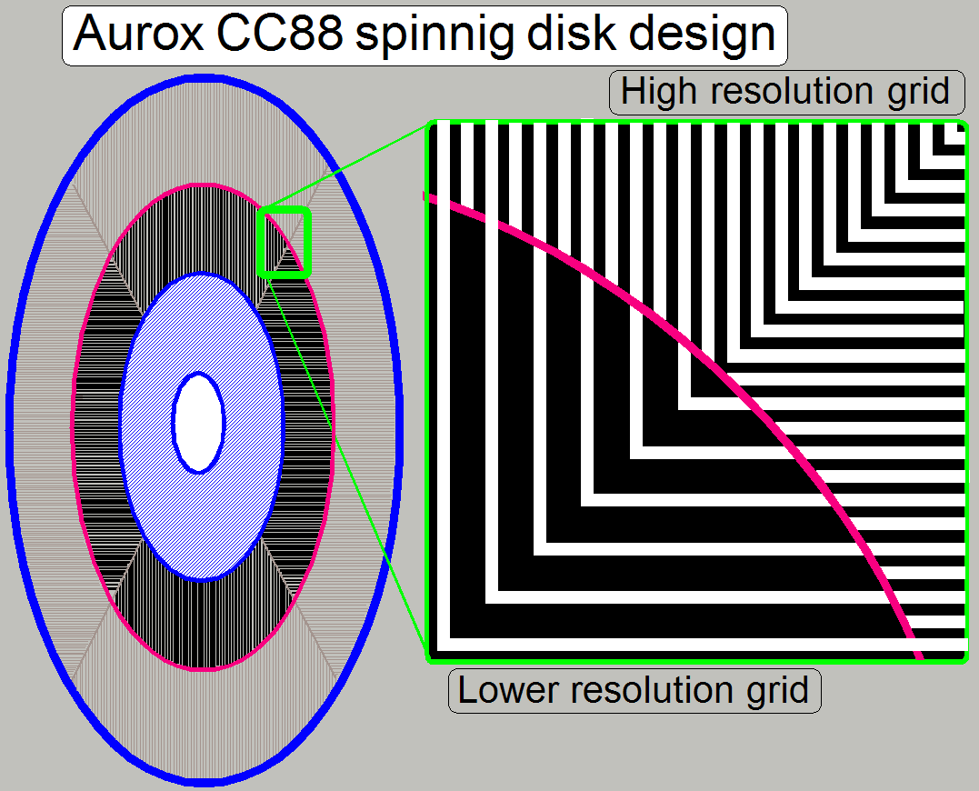 The
spinning aperture disk is divided into 4 sectors and 3 useable sections for
imaging capabilities.
The
spinning aperture disk is divided into 4 sectors and 3 useable sections for
imaging capabilities.
The
sectors contain alternately a vertical slit mask and a horizontal slit mask;
these are realized for each section.
Resolution
High resolution mode 10 lp/mm (line
pair / mm)
Mid resolution mode
5 lp/mm
Low resolution mode 3.3lp/mm
· The
slit and the relevant opaque, mirror part of the disk keep together a so-called
“Line Pair”.
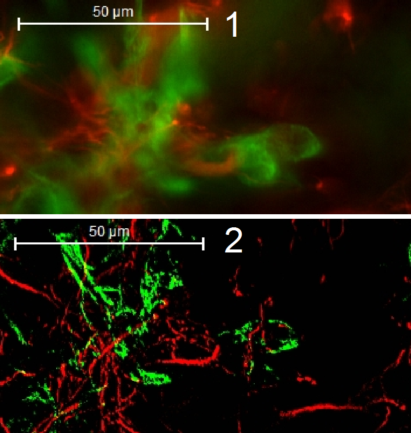
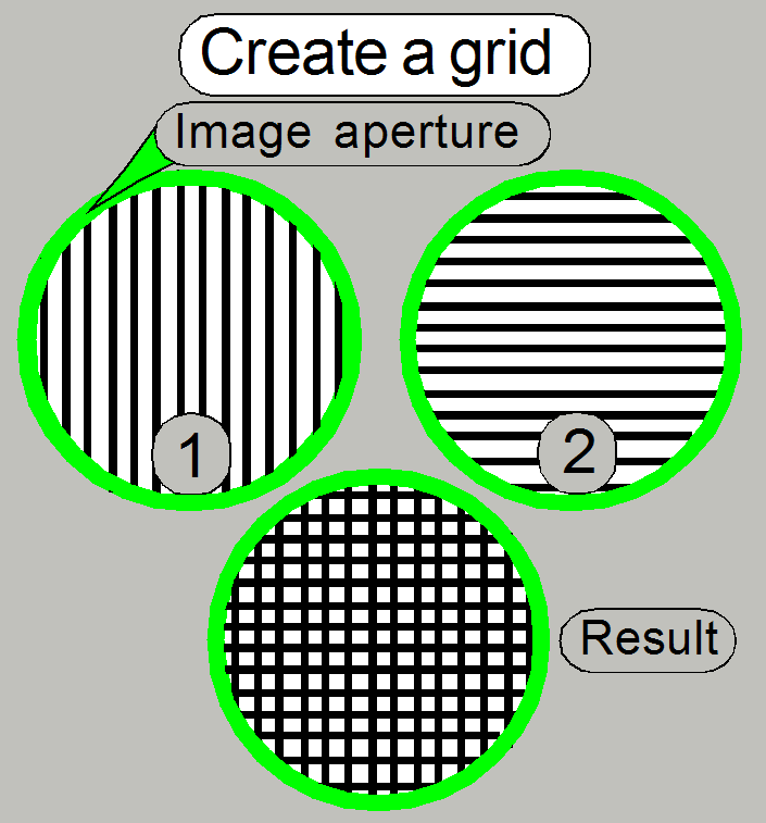 As the disk rotates, the vertical line pairs (1) are
changed to the horizontal line pairs (2) (and vice versa) on the border to the
following sector, so the result will be a cross grid mask of the image, seen by the camera (integral
action by the analog behavior of the image sensor).
As the disk rotates, the vertical line pairs (1) are
changed to the horizontal line pairs (2) (and vice versa) on the border to the
following sector, so the result will be a cross grid mask of the image, seen by the camera (integral
action by the analog behavior of the image sensor).
 Because the spinning disc is inclined in relation to the
optical path, the opaque (mirror) part of the slit grid reflects the
appropriate image part sideward.
Because the spinning disc is inclined in relation to the
optical path, the opaque (mirror) part of the slit grid reflects the
appropriate image part sideward.
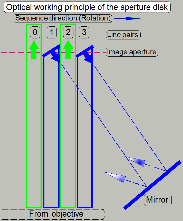
The spinning disk rotates with high speed, the optical
path, defined by the objective aperture will be sampled sequentially, slit by
slit. In other words, the construction of the disk creates in 1 time state a
“pass trough” image, defined by the slit in the disk (0, 2) and also a
reflected image part (1, 3).
The lines 0 and 1 as well as the lines 2 and 3 are
keeping a line pair.
So we can say, the real image part passes through the
disk and light rays out of focus will be reflected.
· The
reflected part (1, 3) performs also an image path!
In the next time state, the disk rotated a little bit,
and the procedure is repeated with the next image part.
· Remember,
that every ¼ revolution of the disk the direction of the grid is changed
from vertical to horizontal and vice versa. By altering the slit direction, a
cross grid is performed.
· Because
always some line pairs staying over the image path at the same time, and the
disk rotate with high speed, the optical image processing is done fast; in a
half revolution of the disk maximal!
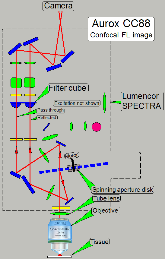
· Excitation
path is not shown here; we are discussing only the real image path!
· To see
an image, the presence of the appropriate excitation wavelength is required in
the optical path!
If the image, gathered by the objective together with
the tube lens arrives to the spinning disk, a pass through and a reflected
image will be created as discussed above.
Both image paths containing the same optical
components with identical parameters.
Finally, both images arriving to the CCD or sCMOS
sensor of the camera.
· We
comment that the resolution and the imaging principle of the camera, as well as
the color deepness (scale deepness of the gray scale) are very important to
produce images of high quality.
The confocal image is created by software; the
reflected image information is subtracted from the passed through image!
Confocal
image = Passed image information –
reflected image information
· During
adjustments and using live view, well observable images are produced if a green
filter cube together with an appropriate tissue is used.
Image of the
PCO.edge 5.5Mp
Each image occupies a half of the sCMOS sensor’s
surface.
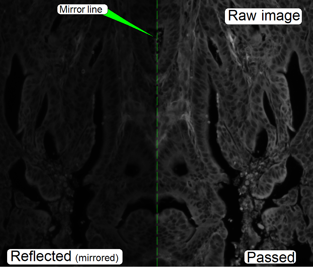 The images are seemingly the same; they are different in
brightness and contrast.
The images are seemingly the same; they are different in
brightness and contrast.
The sensor content (the images) will be separated from
each other by software; the reflected image stays mirrored in relation to the
pass through image.
· If we
add the appropriate pixel information of both images, a traditional widefield
fluorescent image will be the result.
· By
subtracting the appropriate pixel information of the reflected image from the
appropriate pixel information of the passed image, the desired confocal image
will be the result!
Remarks
· The
raw image is in all scanning modes always a gray scale image.
· To
eliminate distortions of the image, the raw images will be rotated cut and
otherwise prepared by software.
· In
fluorescent scan modes (widefield-FL or
· In
brightfield scan mode, the color information is defined by the selected
illumination wave length spectrum, selected in the RGB brightfield illumination
unit.
· The brightness
of the image on the right is a bit increased; otherwise the reflected part
would be too dark.
![]() “RGB
brightfield illuminated optical path”
“RGB
brightfield illuminated optical path”
“Lumencor SPECTRA lght engine”
Optical paths of the CC88
Confocal fluorescent
excitation
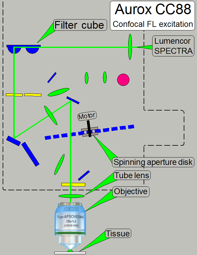 The CC88 allows the excitation of the fluorescent stained
tissue via the relevant filter cube and the objective.
The CC88 allows the excitation of the fluorescent stained
tissue via the relevant filter cube and the objective.
The filter wheel of the CC88 has 4 positions and may
so contain up to 4 filter cubes.
· The
appropriate filter is selected via software buttons (or automatically) before
the FL scan procedure starts and may be changed during the scan session
automatically, if required.
· During
the FL scan procedure the excitation wavelength of the Lumencor SPECTRA is
often changed.
· By
using quad band or multi band filters, the filter cube is rarely changed and
so, scan time is saved.
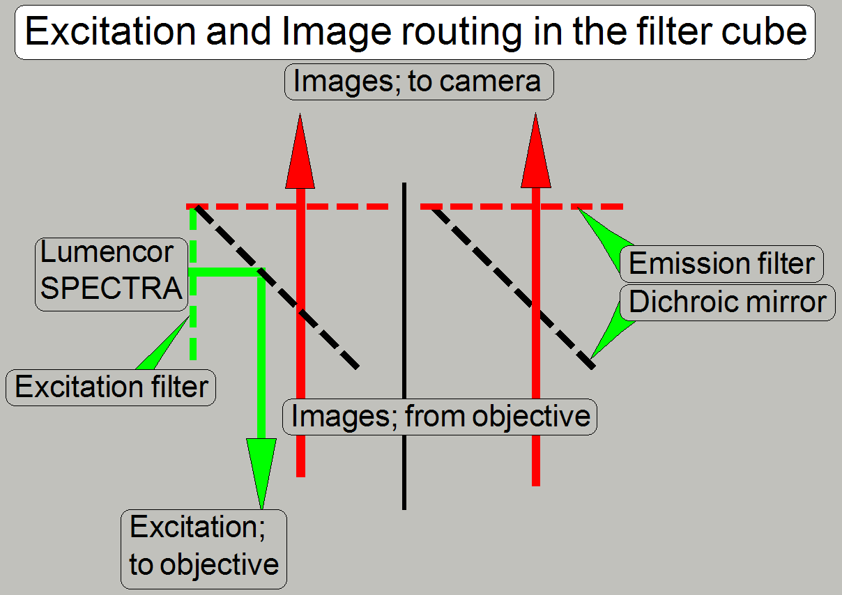
Excitation
light path
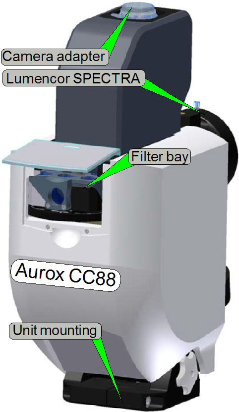
The fluorescent light source, the “Lumencor SPECTRA
light engine®”, is connected to the Aurox CC88 unit via the
fluorescent light source adapter. The
tissue is stained and prepared to fluoresce, if it is excited with a high
intensity light. The emitted light beam of the light source enters the
excitation filter of the “Filter
cube”.
In the filter cube the excitation filter, the beam
splitter and the emission filter are combined for a special excitation and the
relevant emission wave length.
The appropriate wave length of the excitation light beam
passes thru the excitation filter and will be reflected to the objective by the
help of the beam splitter.
The optics in the objective is used to illuminate the
tissue and excites the relevant stain of the field of view.
· The
presence of the aperture disk in the excitation path has no influence of the
exciting quality of the tissue, but the exciting energy is reduced by about
50%. This results in an increased shutter time of the camera.
· Aperture
spinning disk is present in the optical path!
· The
filter position of the filter wheel contains a filter cube!
· Confocal
FL excitation path is not shown here, please see above!
· To see
an image, the presence of the appropriate excitation wavelength is required in the
optical path!
The stain of the tissue fluoresces and the emitted
light rays (in a higher wave length then the excitation wave length; with less
brightness) are collected by the objective; the image passes thru the tube
lens, the beam splitter, and the emission filter to the sensor of the scan
camera.
· The
aperture disk creates a reflected and a pass through image as discussed above!
The wave lengths of the components (the excitation
light wave length, the characteristics of the filter cube and the used stain of
the tissue) are combined for specified light wave lengths; these must be met by
all used components, otherwise the quality of the scanned tissue is reduced or
even bad.
The confocal image is created by software; the
reflected image information is subtracted from the passed through image!
Confocal
image = Passed image information – reflected image information
Important
The characteristic of the excitation filter and the
beam splitter must meet the exciting wavelength of the fluorophore!
· By
subtracting the appropriate pixel information of the reflected image from the
appropriate pixel information of the passed image, the desired confocal image
will be created!
· Aperture
spinning disk is present in the optical path!
· The
filter position of the filter wheel contains a filter cube!
Widefield fluorescent
excitation path
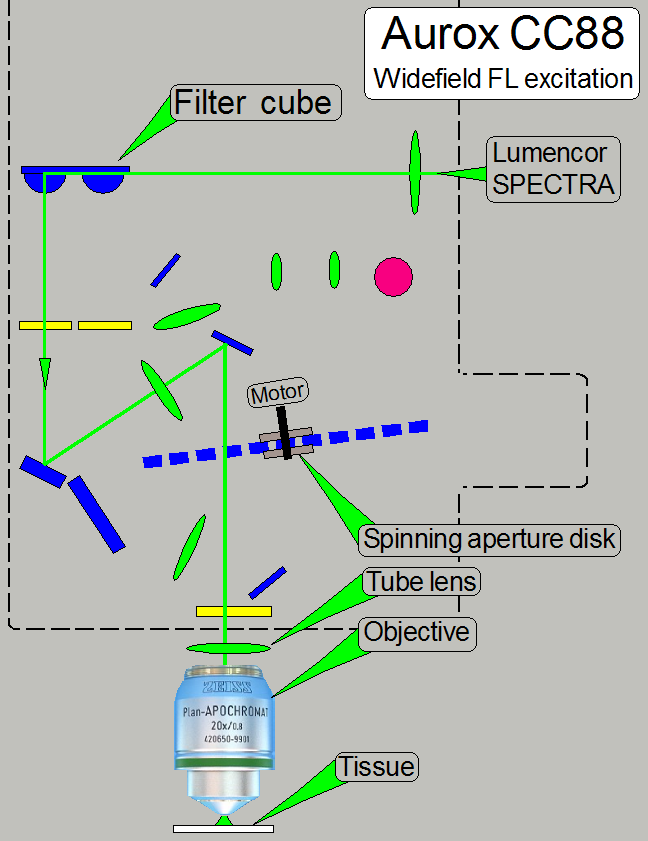
· In
principle the same as shown above!
· Aperture
spinning disk is present in the optical path
· The filter
position of the filter wheel contains a filter cube!
To make the both optical paths (widefield fluorescent
and confocal fluorescent) comparable, the spinning disk is not removed!
Widefield fluorescent image path
·
· To see
an image, the presence of the appropriate excitation wavelength is required in
the optical path!
To make the both optical paths (widefield fluorescent
and confocal fluorescent) comparable, the spinning disk is not removed!
The widefield image is created by software; the
reflected image information is added to the passed through image!
Widefield
image = Passed image information + reflected image information
· By
adding the appropriate pixel information of the reflected image to the
appropriate pixel information of the passed image, the desired, traditional
widefield image is created!
· Aperture
spinning disk is present in the optical path!
· The filter
position of the filter wheel contains a filter cube!
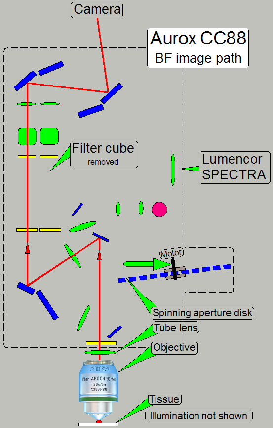 BF scan
In the brightfield scan mode the RGB brightfield
illumination unit is used to illuminate the tissue.
Because the camera PCO.edge 5.5MP is a monochrome camera,
the color of the image is defined by the illumination wave length. The camera
makes a gray scale image in the wave lengths of red, green and blue and so, the
partial color of the tissue is defined. By using the software coloring method,
colored images of a high quality can be produced.
Because the aperture disk is removed from the optical
path, only 1 image will be created.
· The
created image occupies only a half of the sCMOS sensors surface
· Aperture
spinning disk is removed from the optical path
· The
filter position of the filter wheel is empty; a filter cube must not be
present!
![]() “Brightfield
illuminated optical path”
“Brightfield
illuminated optical path”
Components;
construction
Filter
cube
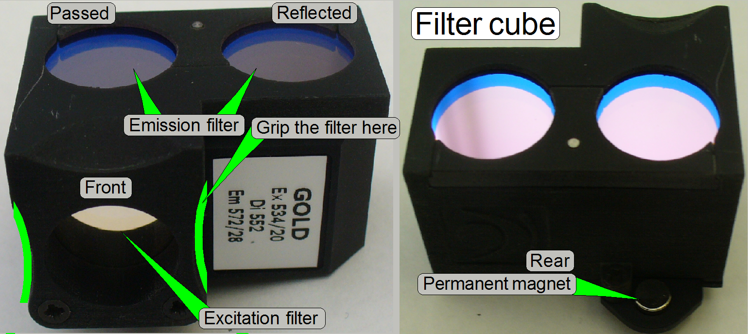 The filter
sets for fluorescent scan
exist in various filter combinations
and are used to filter the light of a specific wavelength to excite the
fluorescent stain of the tissue (Excitation filter)
and to filter the relevant, emitted light of the stained tissue (Emission
filter).
The filter
sets for fluorescent scan
exist in various filter combinations
and are used to filter the light of a specific wavelength to excite the
fluorescent stain of the tissue (Excitation filter)
and to filter the relevant, emitted light of the stained tissue (Emission
filter).
A wide spectrum of filter sets and filter cubes is
available from major microscope manufacturers via
product number. If you are self assembling the filter set into a cube, take
care on the positions where the filters are mounted. The Emission filter shows
always to the camera and the Excitation filter to the fluorescent light source.
The Excitation filter, the Emission filter and the Beam splitter are combined
for a special light wave length (range) and therefore they must not be mixed
with parts of another set!
![]()
·
“Matching
Fluorescent Probes with Nikon Fluorescence Filter Blocks”; interactive;
explains working principles
· “Setup filters”
(to assign colors, color channels, and filter positions in Pannoramic scanners)
 The filter sets are assembled to a filter
block or filter cube. The wavelength varies in the range between ultra violet excitation (350 nm) -
blue emission (450 nm) and orange excitation (600 nm) - deep red
emission (690 nm). The beam splitter reflects the shorter light wavelength
during the light with the longer wavelength passes thru it.
The filter sets are assembled to a filter
block or filter cube. The wavelength varies in the range between ultra violet excitation (350 nm) -
blue emission (450 nm) and orange excitation (600 nm) - deep red
emission (690 nm). The beam splitter reflects the shorter light wavelength
during the light with the longer wavelength passes thru it.
- Keep the surfaces of the excitation filter
and the emission filters clean!
![]() ‘Introduction
to Fluorescence Filters” (Semrock)
‘Introduction
to Fluorescence Filters” (Semrock)
“Cleaning optics” (stored in this description)
and
“Cleaning Optical
Filters” (Semrock)
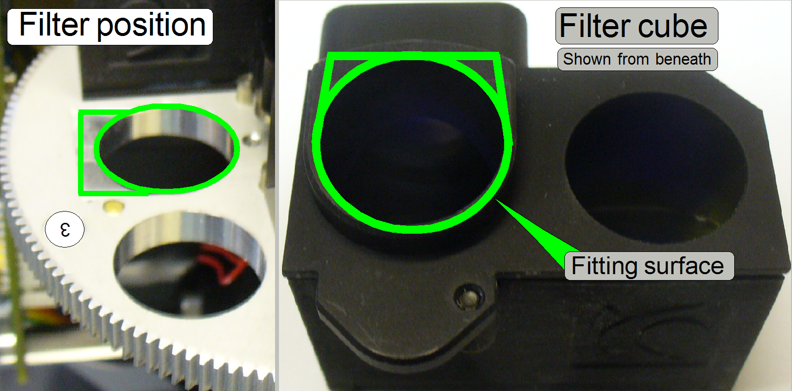
The filter fixing is realized by a permanent magnet.
If the filter is inserted in the appropriate position of the filter wheel, the fitting
surface defines the proper position of the filter cube in relation to the
optical axis; the permanent magnet fixes this position.
- Keep the position surfaces of the filter cube and the filter wheel
clean and dry.
 Stop the operation in progress and open the filter bay door
of the Aurox CC88 (the CC88 remains under power) and insert the filter into the
filter cube position of the filter wheel until the cube is hold by the
permanent magnet and fits its position properly.
Stop the operation in progress and open the filter bay door
of the Aurox CC88 (the CC88 remains under power) and insert the filter into the
filter cube position of the filter wheel until the cube is hold by the
permanent magnet and fits its position properly.
· Rotate
the filter wheel into the required turret wheel insert position manually and
insert the filter cube.
· Check
the proper position of the filter cube in the filter wheel manually; the filter
should rest in its position, corresponding to the designed area and should fit
the surface of the filter wheel without a gap!
Important
· The
fourth filter position has to be left empty, it must not contain a filter cube,
because this position is used for calibration capabilities!
For adjustments of the optical path, a green filter cube by
using an appropriate tissue is recommended. Nevertheless, the finished
adjustments should be checked by scanning tissue parts with the entire filter
set of the user!
Remove
the filter cube
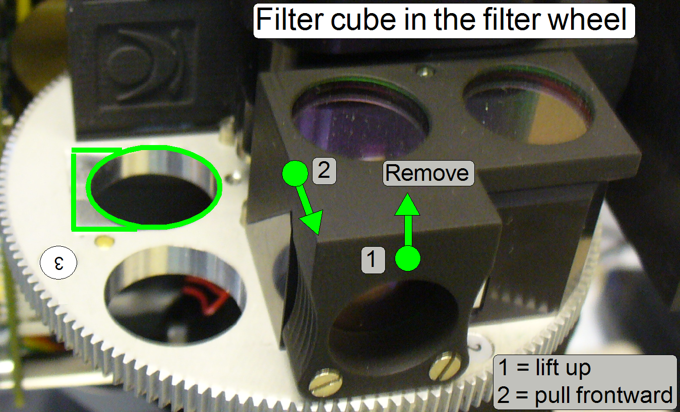 Lift up the filter cube carefully on the gripping part
until the fitting surface releases the filter cube, then move the entire filter
cube frontward.
Lift up the filter cube carefully on the gripping part
until the fitting surface releases the filter cube, then move the entire filter
cube frontward.
.
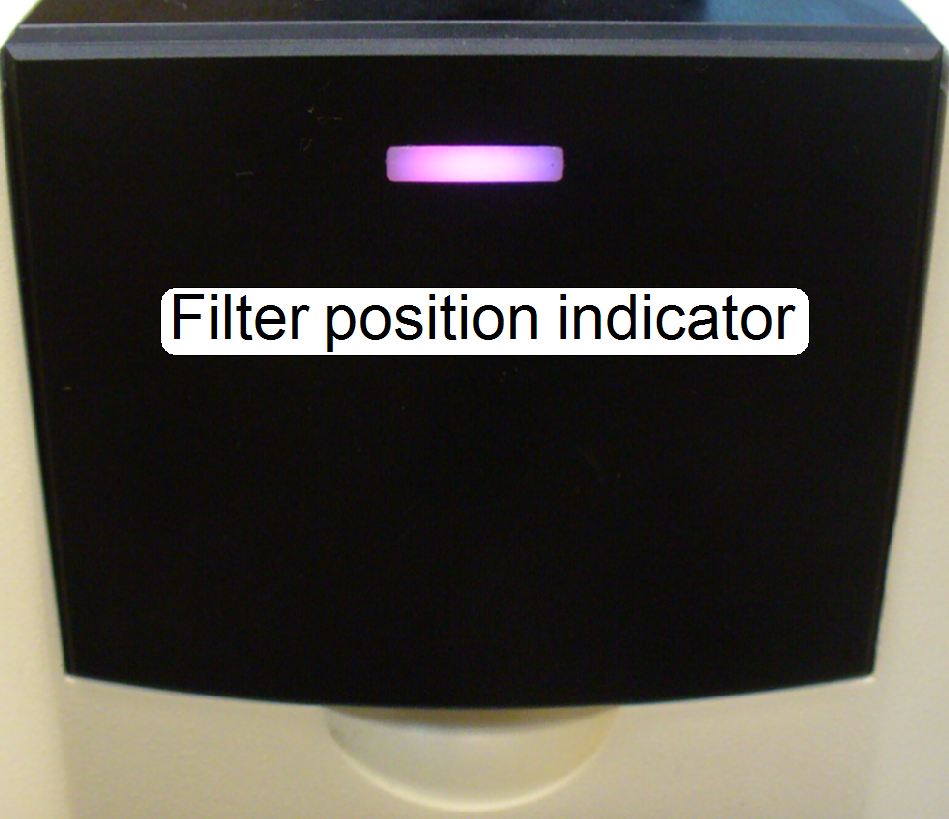
LED indicator of the filter bay door
Dark
The
unit is powered off.
If the power is
supplied, the filter cube was inserted, the bay door is closed and the
indicator LED remains dark, the filter was inserted improperly!
· Open
the bay door, rotate the filter wheel carefully, manually until the filter cube
arrived into the filter’s insert position and check so the proper position of
all inserted filters!
Purple
· If the
filter cube was inserted, the bay door is closed and the indicator LED lights
purple, all of the inserted filters are in proper position!
Blue
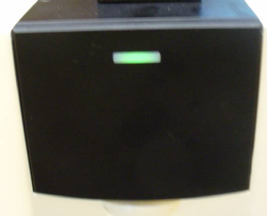 Filter
position 1 is in the optical path.
Filter
position 1 is in the optical path.
Green
Filter
position 2 is in the optical path.
Red
Filter
position 3 is in the optical path.
Filter
position 4 is in the optical path.
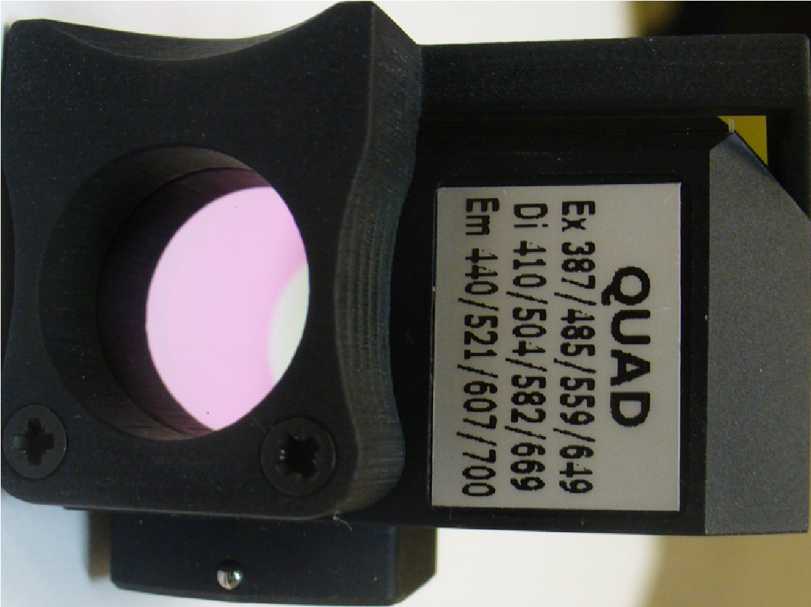
Quad
band:
 http://www.semrock.com/SetDetails.aspx?id=2777
Excitation filter wavelengths [nm]: 387 / 485 / 559 / 649
Dichroic Beamsplitter edge
wavelengths [nm]: 410 / 504 / 582 / 669
Emission filter wavelengths [nm]: 440 / 521 / 607 / 700
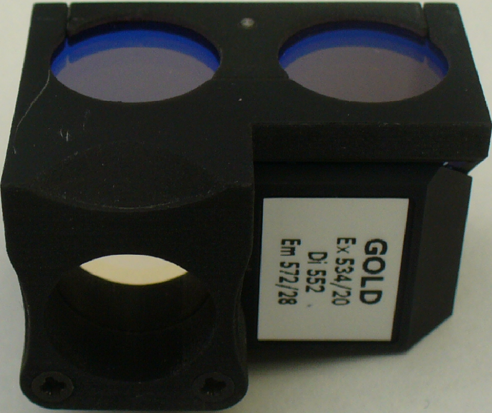
 Spectrum Gold:
http://www.semrock.com/SetDetails.aspx?id=2794
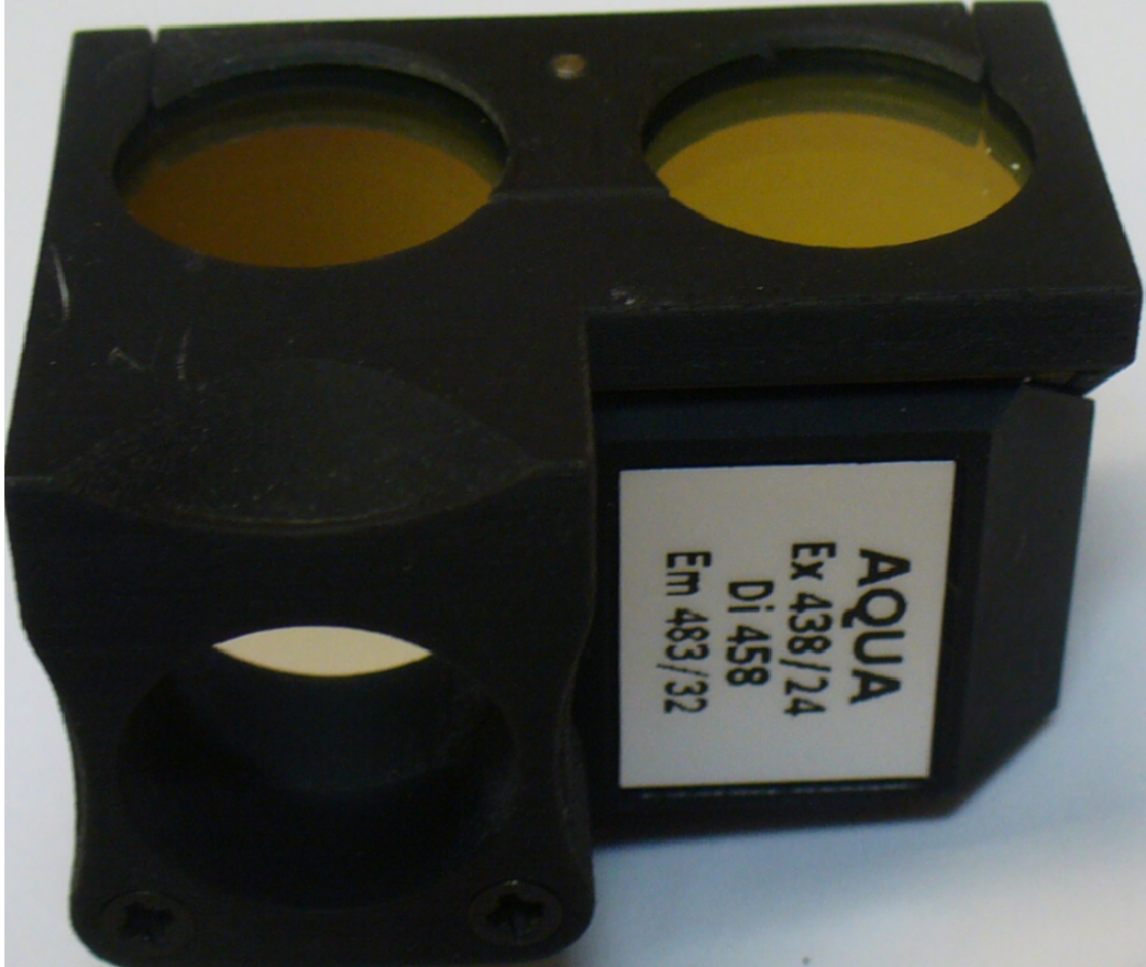 Spectrum Aqua
http://www.semrock.com/SetDetails.aspx?id=2941
http://www.semrock.com/SetDetails.aspx?id=2797
Virtual tissue
 To allow analyzing of parts in the tissue (e.g. nuclei, or
DNS fractions), parts can be stained with special stain. A
wide range of fluorescent stains (fluorophores) is available for different
markers. Each stain is excited by a special wave length of the excitation light
and emits light in another, relevant wavelength. One tissue can be stained with
more than only one stain (fluorophore), so different parts of the tissue can be
visualized in different colors at the same time.
To allow analyzing of parts in the tissue (e.g. nuclei, or
DNS fractions), parts can be stained with special stain. A
wide range of fluorescent stains (fluorophores) is available for different
markers. Each stain is excited by a special wave length of the excitation light
and emits light in another, relevant wavelength. One tissue can be stained with
more than only one stain (fluorophore), so different parts of the tissue can be
visualized in different colors at the same time.
To reduce the exposure time of the camera and to
produce a high quality of the virtual fluorescence tissue, the used filter cube
must match the excitation wavelength (the source wave length to excite the
stain) AND the emission wavelength (the emitted wavelength of the stain) also.
Furthermore, the emitted wavelength of the exciting light source must be able
to excite the stain in its wavelength.
To produce a high quality of the virtual fluorescent
tissue and to reduce the exposure time during fluoresce scan the following
parameters are very important:
1) The characteristic of the exciting
light source (emitted wave lengths)
2) The characteristic of the used
filter cube (exciting and emission wave length) and
3) The characteristic of the used
stain (exciting and emitted wave length).
The best virtual tissue quality (and the shortest
exposure time also) will be reached if all the characteristics are optimal met,
otherwise the exposure time will rise up and the virtual tissue becomes more
poor.
If the wave lengths of one component differ too much,
the scanned quality is very poor or even bad!!
- Keep the surface of the cover slip and the surface of the slide
bottom clean; see also: “Cleaning optics”
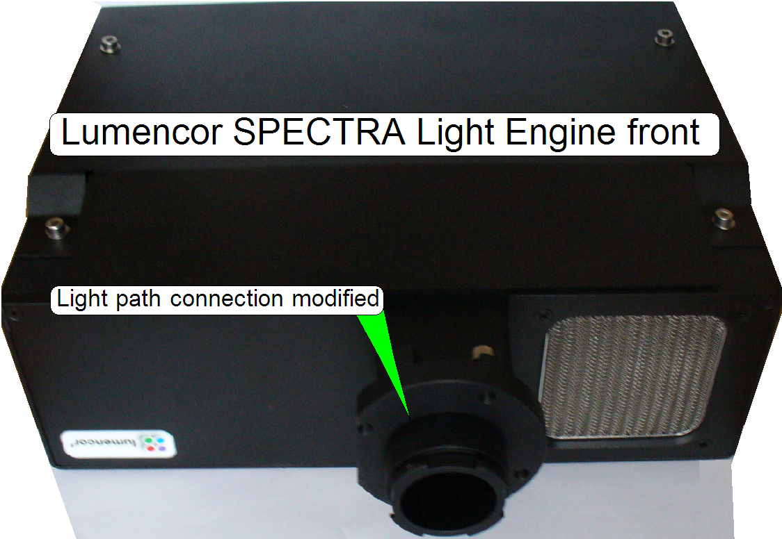
Lumencor SPECTRA
light engine®
Precautions
 Never look directly into the beam of the
fluorescent light source! For further precautions please, refer to the manual
for the fluorescent light source you are using!
Never look directly into the beam of the
fluorescent light source! For further precautions please, refer to the manual
for the fluorescent light source you are using!
· This
light source generates monochromatic exciting wave lengths; the desired wave
length can be selected by software. With this light source single band or multi
band filters can be used likewise.
![]() “Lumencor SPECTRA light
engine®” and
“Lumencor SPECTRA light
engine®” and
“Mounting of the Lumencor SPECTRA
light engine®” later in this chapter
Spinning disc unit
Detailed information about the unit “Aurox CC88” can also be found in
“User Manual for CC88
spinning-disk confocal imaging unit” pdf-file;
stored in this description
Mount the Aurox CC88 spinning disk unit
· 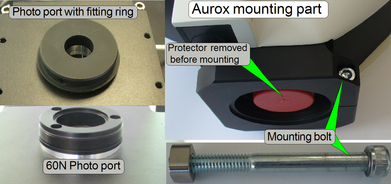 Drive the fitting
ring onto the 60N Photo port manually, until it stops
Drive the fitting
ring onto the 60N Photo port manually, until it stops
· Loosen the
mounting bolt on the Aurox unit a bit.
· Put the Aurox unit
onto the fitting ring so, that the fluorescent light input shows to the
Lumencor SPECTRA light engine.
· 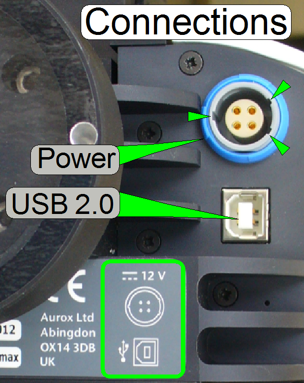 Connect the
appropriate cables to the unit!
Connect the
appropriate cables to the unit!
· The USB port
address will be found automatically by the scan program and the service
program; it must not be defined explicitly!
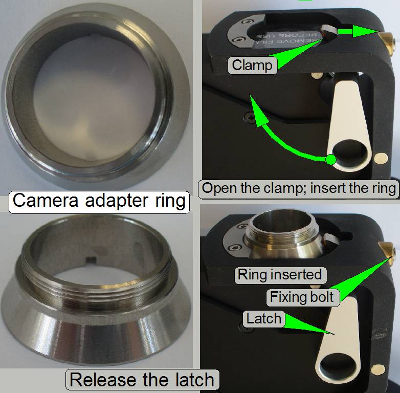 The C-mount camera
adapter ring is situated between the camera and the Aurox CC88 spinning disk
unit.
The C-mount camera
adapter ring is situated between the camera and the Aurox CC88 spinning disk
unit.
· The usable
magnification of the C-mount Camera Adapter Ring is always 1:1!
· Drive the C-mount
Camera Adapter Ring manually first onto the camera until it stops
· Loosen the fixing
bolt
· Move the latch as
shown to open the clamp and insert the C-mount Camera Adapter Ring with camera
· Release the latch
and adjust the camera rotation angle
· Tighten the fixing
bolt
· Protector foils and means of the
optical path must be removed just before mounting!
Mounting of the Lumencor SPECTRA light
engine®
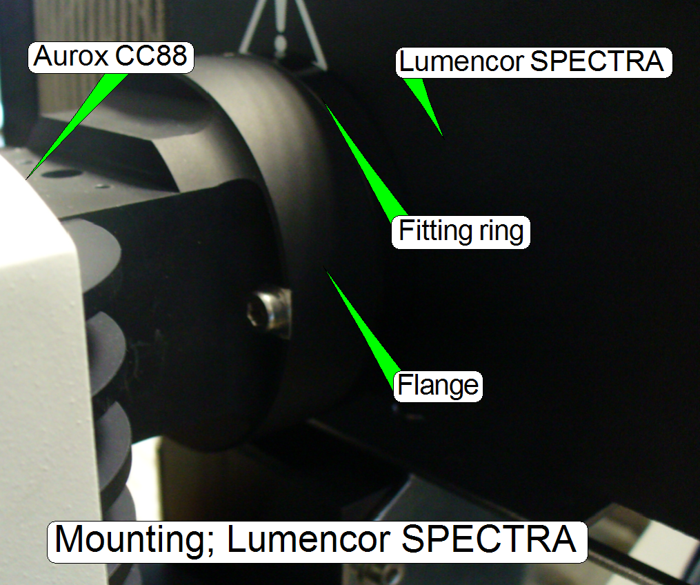
- The fitting
ring between the flange of the Aurox CC88 and the Lumencor SPECTRA may be
not present!
- Adjust the position
of the excitation light source on its table and the position of the table
so, that the light travels on the optical axis of both components!