
Housing, construction
For technicians and
partly for sales managers!
This chapter handles the construction and components of the housing as
well as the construction of the entire scanner. Mainly mountings of the units
and components, relations of the units to each other and the construction of
mechanical units are introduced.
· Description is
based on the software version 1.19 and the scanner “Pannoramic Confocal”.
 The housing of the scanner PCON consists of:
·
Base
(mounting) frame with 6 rubber
feet; and 4 handles
(for movements of the scanner).
·
Housing
Switch with power LED on the left sided side wall
·
Lock
mechanism to open the right handed side wall and for other covers.
·
Tray's
insert opening to insert or remove the slide tray from the scanner.
·
Motorized
front door, to reach and fill the Immersion liquid feeder
·
Rear cover with power input,
cable entry guide for the camera and other cables.
·
Illuminated
logo in the front door
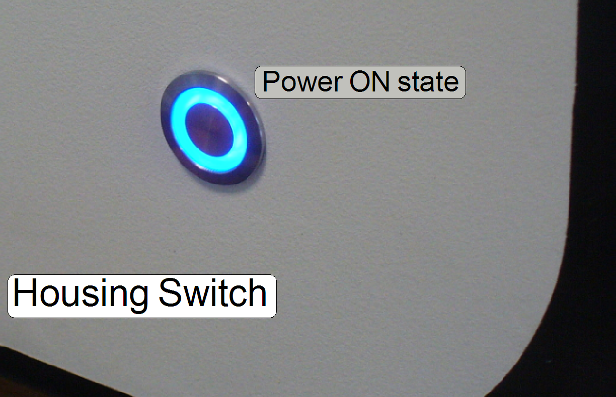
· Switch on the Mains Switch on
the rear of the scanner
· Push the Housing Switch on the left side to
switch on the scanner
· The housing switch
is also used to switch off the entire scanner if any emergency situation
occurs.
· If the scanner was
switched off while the software is running, the running processes has to be
finished, before the software can be started again; see also: “Shut down processes”
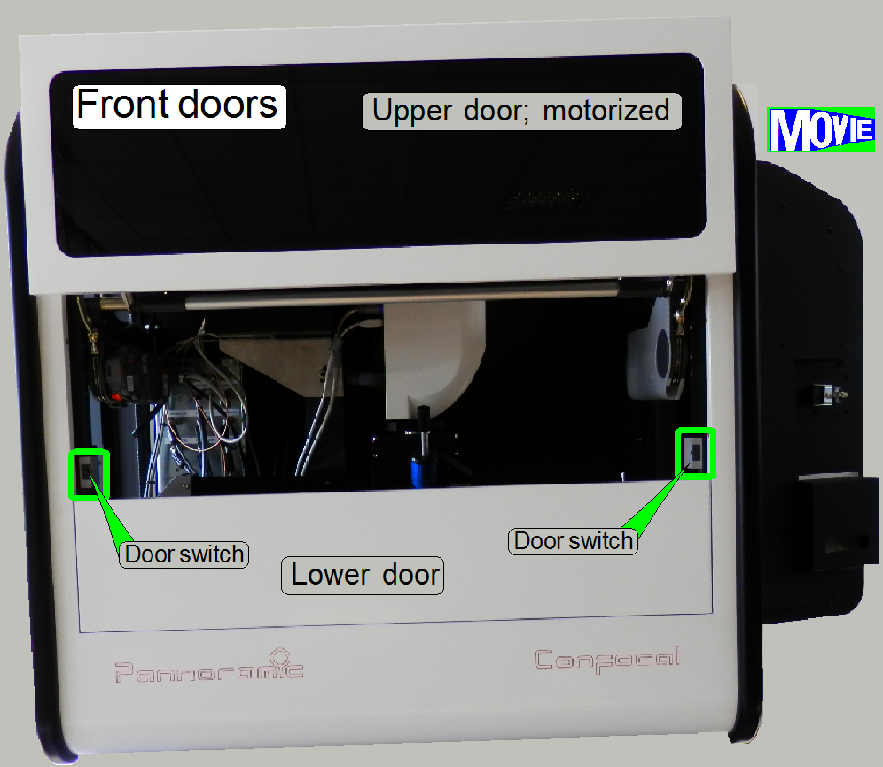 To reach the
immersion liquid feeder quickly, the front of the scanner can be opened by a
motorized upper front door.
To reach the
immersion liquid feeder quickly, the front of the scanner can be opened by a
motorized upper front door.
For service purposes, the lower door may be opened manually.
· By pushing the
upper door on the position, where a switch is located, the door will be opened
by a motor driven mechanics.
· If the door is
open, easily push one of the switches to close the door.
Remark
The door can only be opened, if the scan software allows it. In not allowed states
of the SlideScanner.exe the power is not supplied to the motor and so, the door
can not be opened.
Watch video: “Front door open and
close”
See also: “Aventos
servo drive unit”
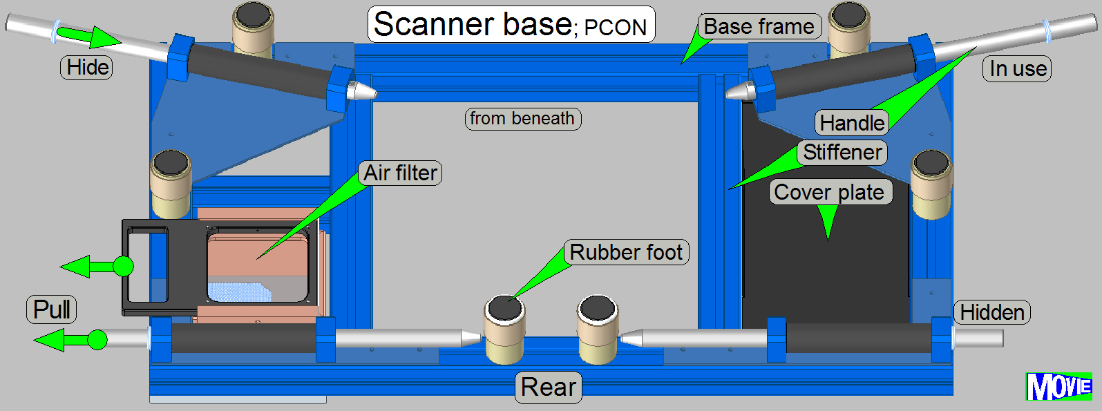 The scanner base contains the
following components:
The scanner base contains the
following components:
· Base frame, with the
mountings for components.
· The cover plate;
it defines also the distance of the frame stiffener to the right frame part.
· Handles with mounting plates;
the mounting plates increasing the stability of the frame also
· 6 rubber feet to reduce
noise and vibration
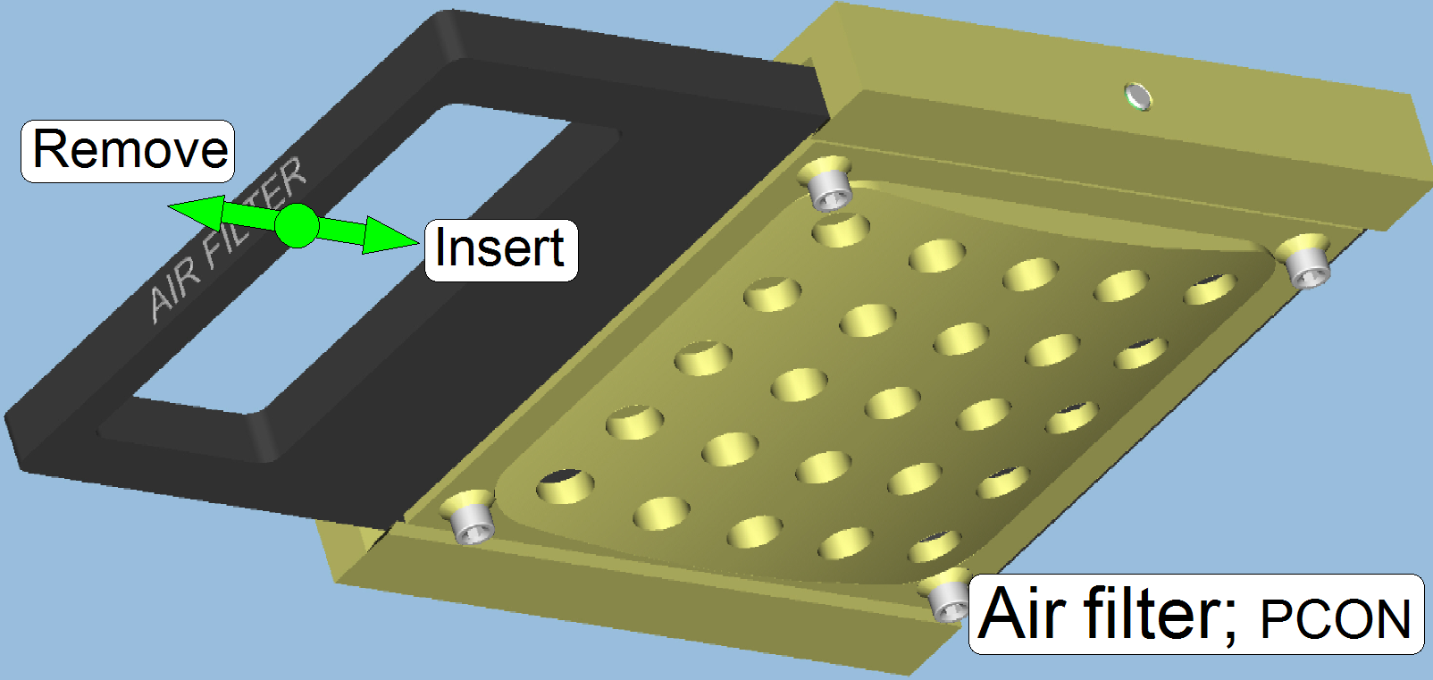
· Air filter with mounting;
for the power tower fan
· Mountings for the housing
and the power tower (not shown)
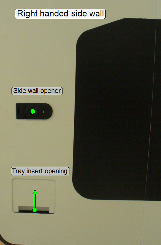
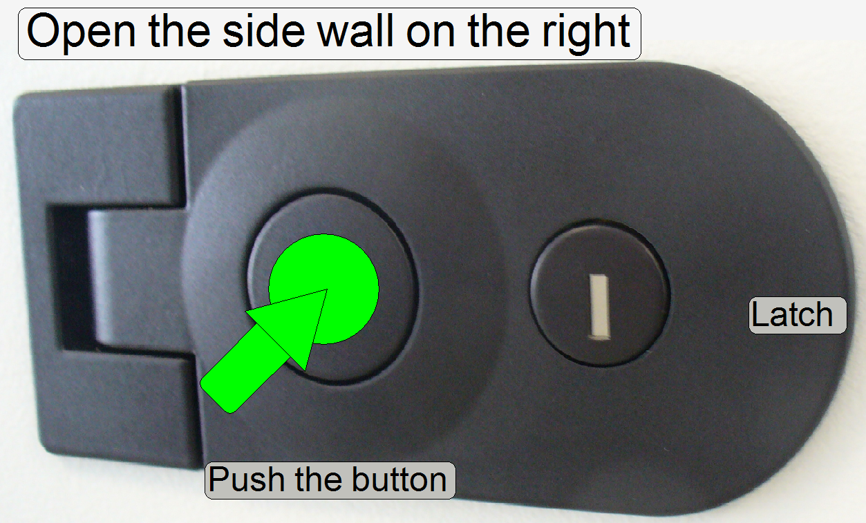
· By pushing the
button, the lock will release and the side wall can be opened by pulling the
latch
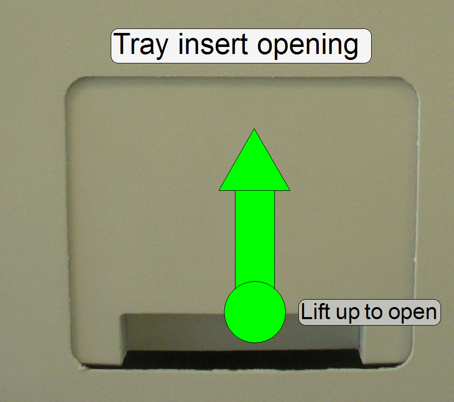
· If the tray
opening door is moved upward, the tray can be inserted or removed
Construction; PCON
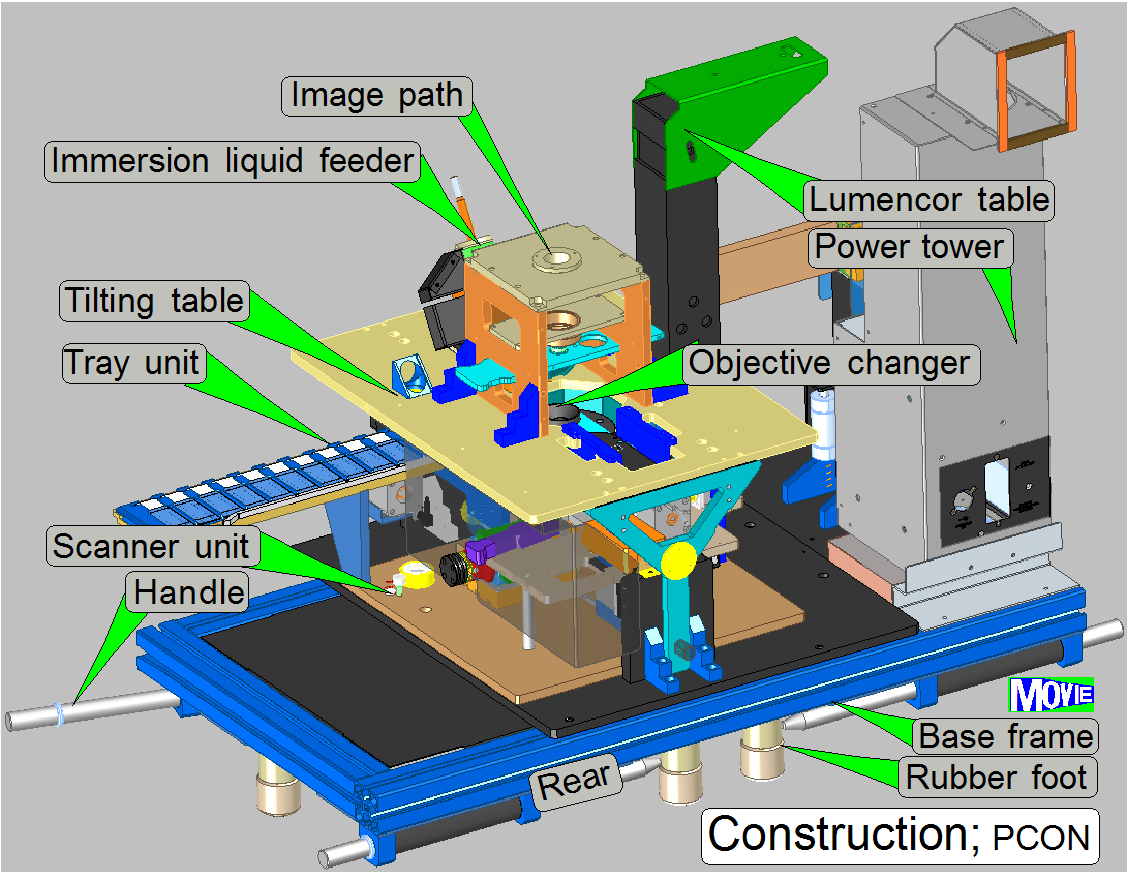 The scanner Pannoramic Confocal consists of the
following main components:
The scanner Pannoramic Confocal consists of the
following main components:
1.
Mounting
(Base) frame; with rubber feet and handles
2.
Scanner
unit
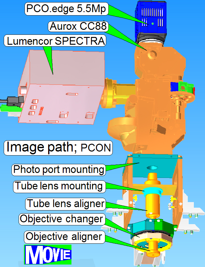
3.
Image path with objective
changer and tube lens
4.
60N Photo port with Spinning
disk unit and scan camera PCO.edge
5.5Mp (not shown)
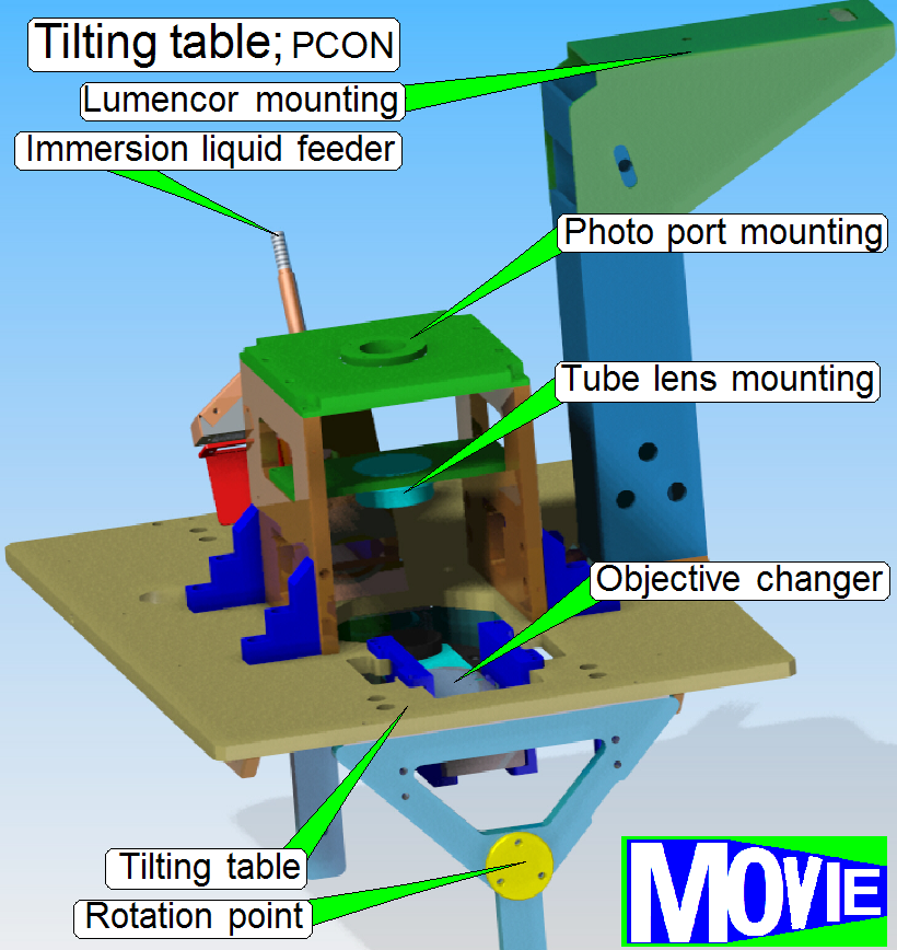
5.
Tilting table with immersion liquid feeder, objective
changer and entire image path
6.
Mounting for the FL illumination unit table; for Lumencor SPECTRA light engine
7.
Power tower; with
power supply
and main control electronics
· For
safety regulations regarding human health and scanner functionality please
refer to: Precautions
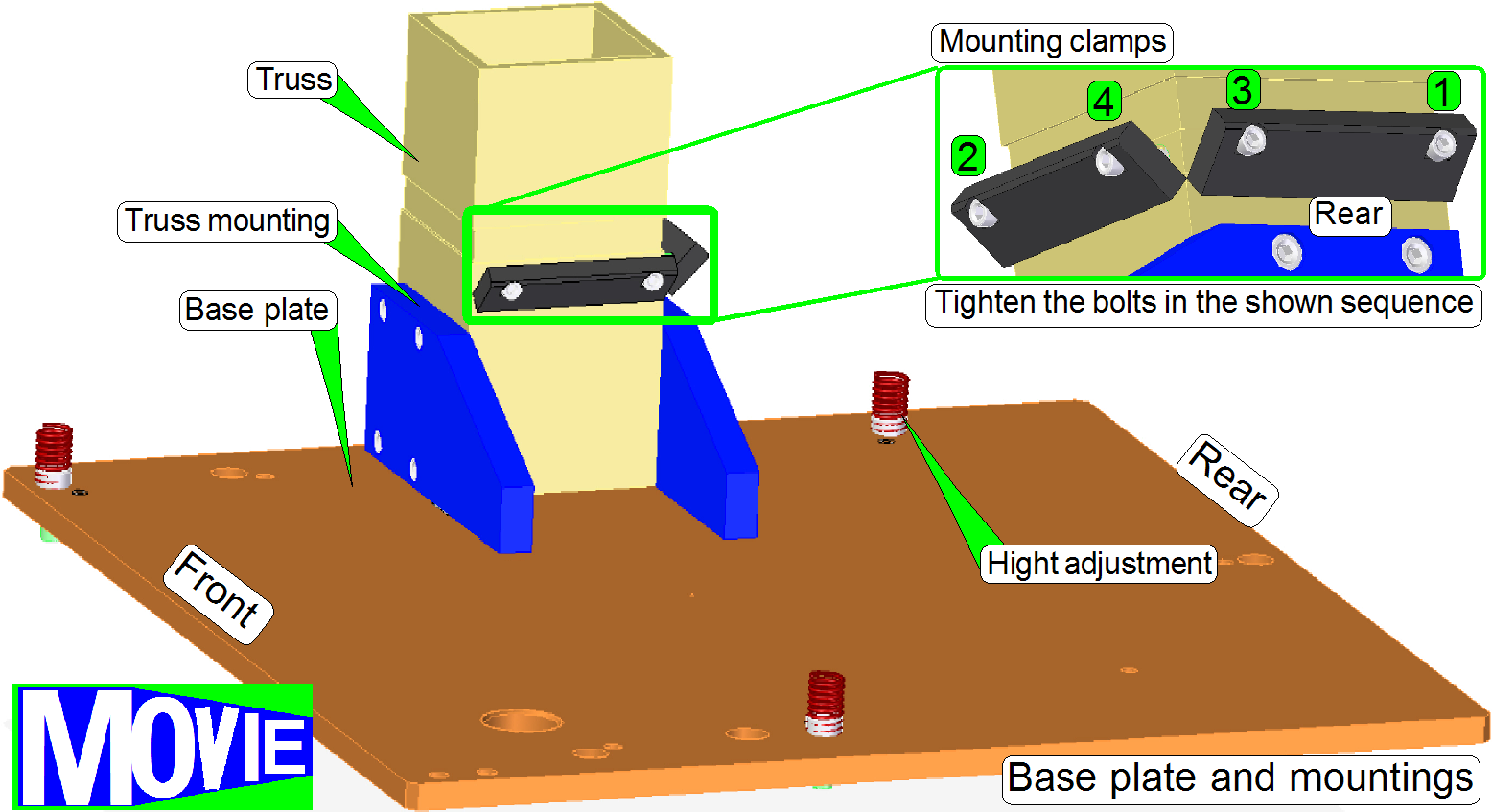
Scanner plate with
the mounting to the truss
RGB brightfield
scan illumination
Tray holder with
conveyor unit
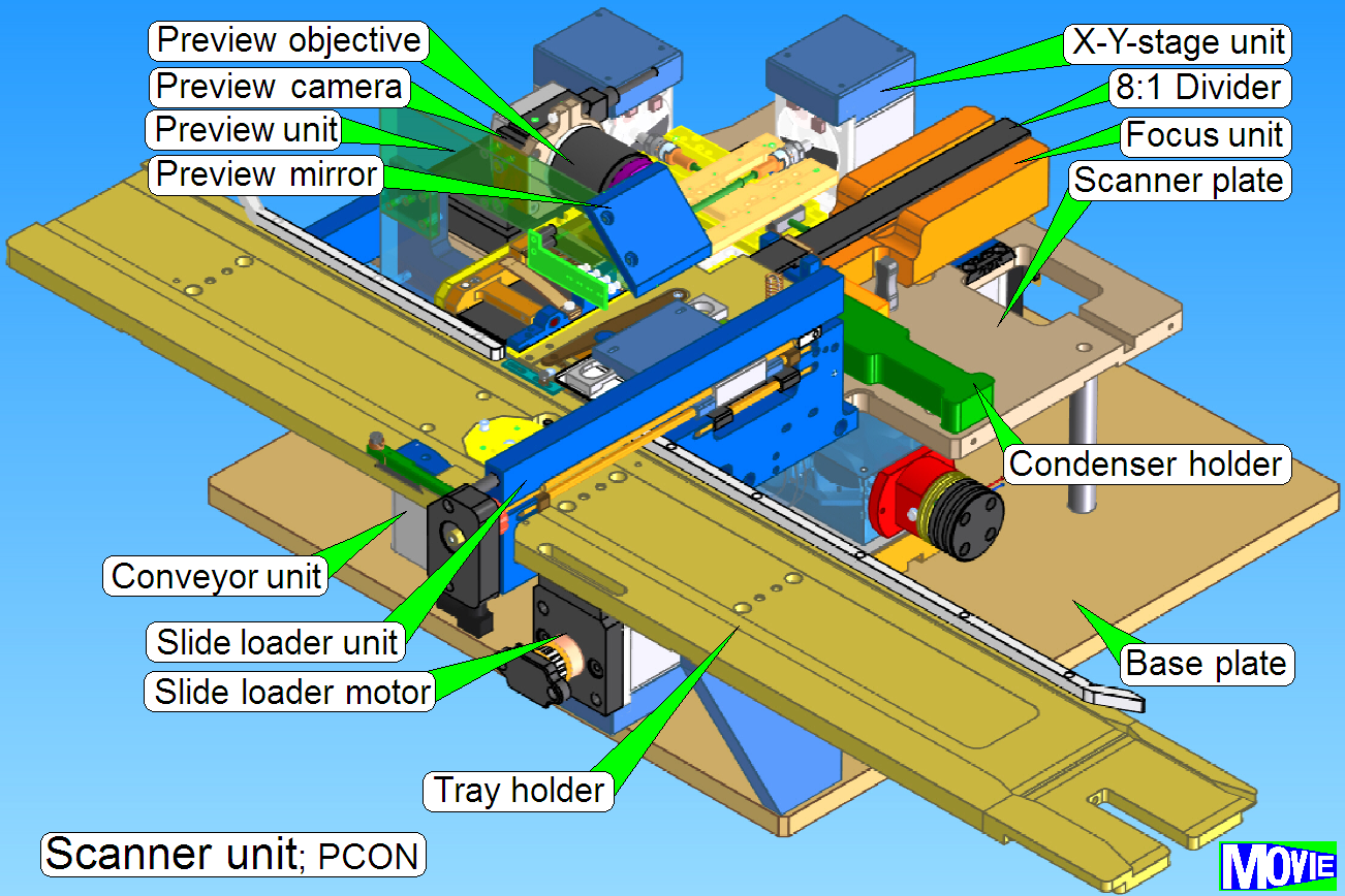
The scanner unit consists of:
·  Base plate with mounting and height adjustment
related to the objective’s focus point
Base plate with mounting and height adjustment
related to the objective’s focus point
· Truss with mounting clamps for the Scanner plate
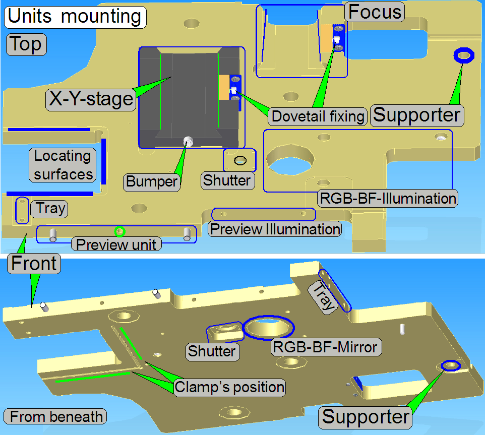 The scanner plate contains the mountings for
the units
The scanner plate contains the mountings for
the units
· Truss,
with Locating
surfaces
· Focus
unit’s dovetail mounting
· Focus unit’s dovetail
fixing
· X-Y-stage
unit’s dovetail mounting
· X-Y-stage unit’s
dovetail fixing
· Preview
unit’s horseshoe mounting
· Preview illumination
unit’s mounting
· Brightfield
scan illumination mounting (RGB_BF_Illumination)
· X-Y-stage
unit bumper with mounting
To define the plane of the scanner unit in relation to
the tilting table and to ensure the straightness of the optical axis, locating
surfaces are used.
See also: “Scanner
unit mounting” and “Tightening
sequence”
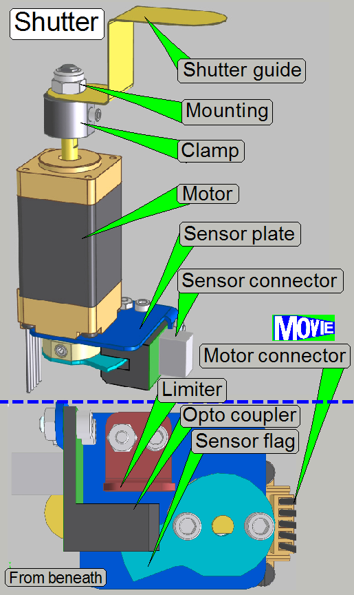 The mechanical
shutter keeps a condenser cover while fluorescent scan sessions and it avoids
so reflections of the condenser; the excitation of the stained tissue is done
via the objective.
The mechanical
shutter keeps a condenser cover while fluorescent scan sessions and it avoids
so reflections of the condenser; the excitation of the stained tissue is done
via the objective.
The shutter mechanics was removed from the focus unit
(in relation to previously developed scanners) and the shutter motor is placed
onto the scanner plate from beneath.
The shutter guide is driven by a stepper motor and the
positions shutter on and shutter off are defined by the sensor flag and the
defined number of steps; the sensor flag defines the home position also.
The limiter does not allow the rotation of the shutter
guide in wrong direction.
The driver electronics of the shutter motor is mounted
onto the scanner plate from beneath, close to the shutter motor.
Further information can be found in the chapter: “Mechanical shutter”, “Shutter motor”; and “Shutter sensor”
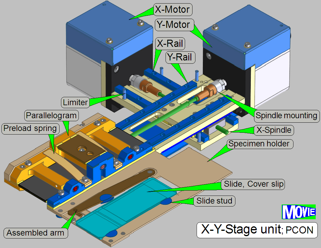
X-Y-stage unit
The X-Y-stage unit can be removed or mounted only, if the
entire base plate with scanner plate is removed!
- Remove
the condenser unit
- Remove the Focus unit
- Remove the X-X-stage unit
Mount
the X-Y-stage unit
- Mount the X-X-stage unit
- Mount the Focus unit
- Mount the
condenser unit
See also: “X-Y-stage unit”
X-Y-stage unit bumper with mounting
 The
distance of the X-Y-stage unit in relation to the tray unit is defined by the
X-Y-stage unit bumper.
The
distance of the X-Y-stage unit in relation to the tray unit is defined by the
X-Y-stage unit bumper.
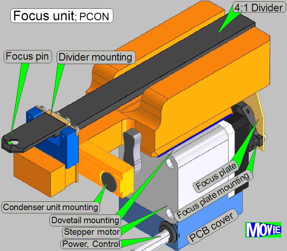
Focus unit
The focus unit can be removed or mounted only, if the entire
base plate with scanner plate is removed!
- Remove
the condenser unit
- Remove the Focus unit
Mount
the focus unit
- Mount the Focus unit
- Mount the
condenser unit
See also: “Focus unit”
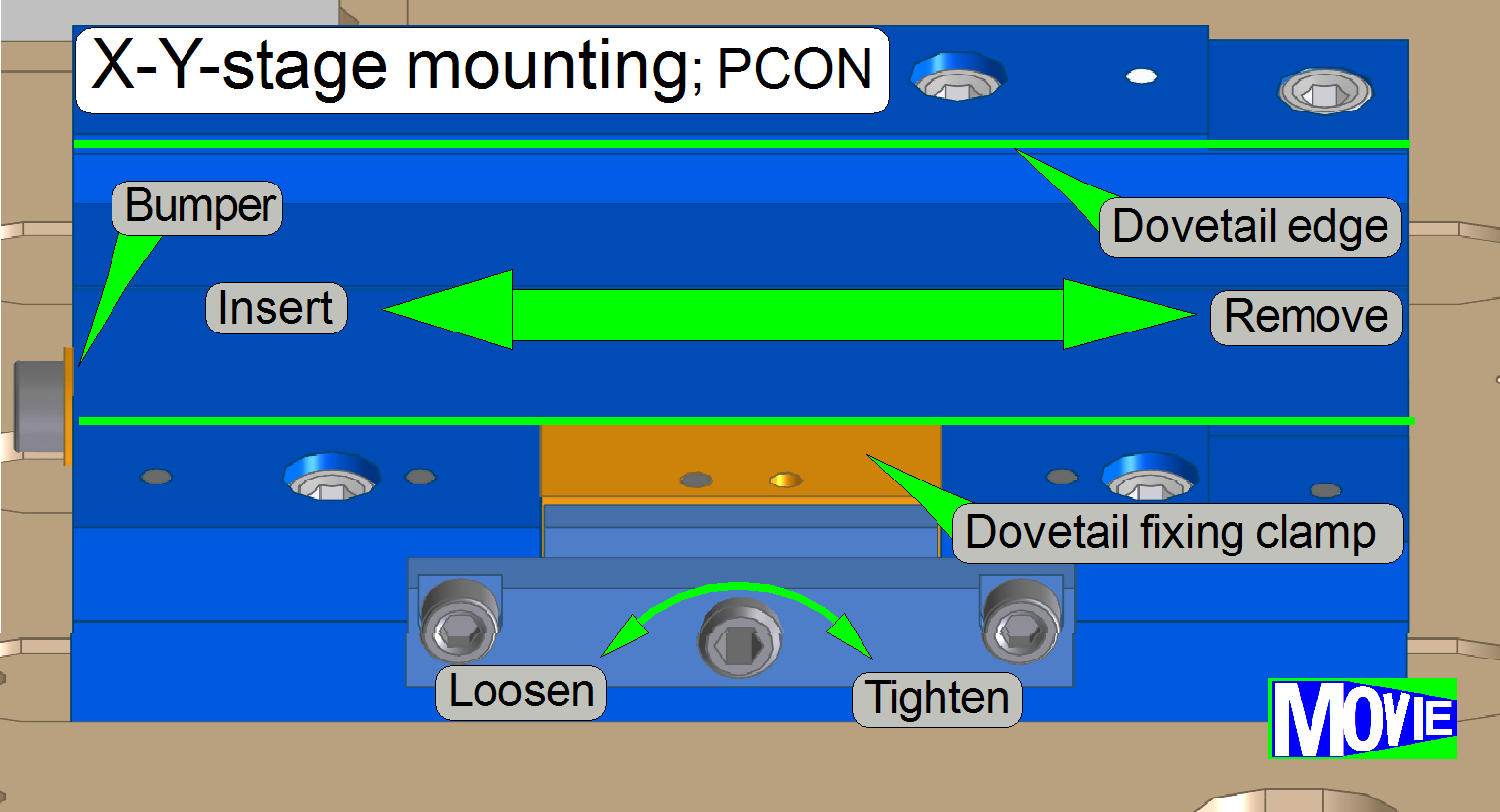
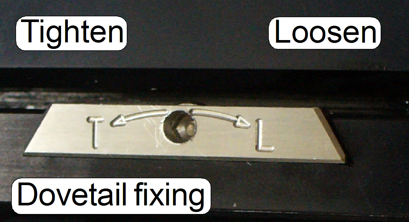
Focus unit’s dovetail mounting
 The dovetail mounting
ensures the proper position of the X-Y-stage unit and the focus unit in
relation to each other.
The dovetail mounting
ensures the proper position of the X-Y-stage unit and the focus unit in
relation to each other.
The mounting of the focus
unit and the mounting of the X-Y-stage unit are realized with dovetails; these
are hold by dovetail fixing clamps.
- Focus unit: Rotate
the 2.5 hex key
wrench clockwise to open (loosen) the dovetail clamp.
- X-Y-stage unit: Rotate the 2.5 hex key wrench
counterclockwise to open (loosen) the dovetail clamp.
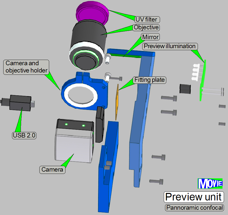
 The horseshoe is
the mounting part of the preview unit, and contains the mountings of following
components:
The horseshoe is
the mounting part of the preview unit, and contains the mountings of following
components:
- Objective
and camera holder with fitting plate
- Preview mirror mounting (can not be removed!)
- Barcode
illumination
The entire preview unit is situated on the edge of the
scanner plate, parallel to the magazine unit.
The position is fixed with two fixing pins and hold by
the mounting bolt. To allow an easy remove of the optics, the horseshoe is
divided into a camera half and a mounting half.
See also: “Scanner unit”
Remove the preview unit
· Remove
the mounting bolts and separate the camera half from the mounting half.
Mount the preview unit
· Fit the
fixing pins of the mounting half with the position fixing holes of the camera
half and drive in the half’s mounting bolts.
Preview unit’s horseshoe mounting
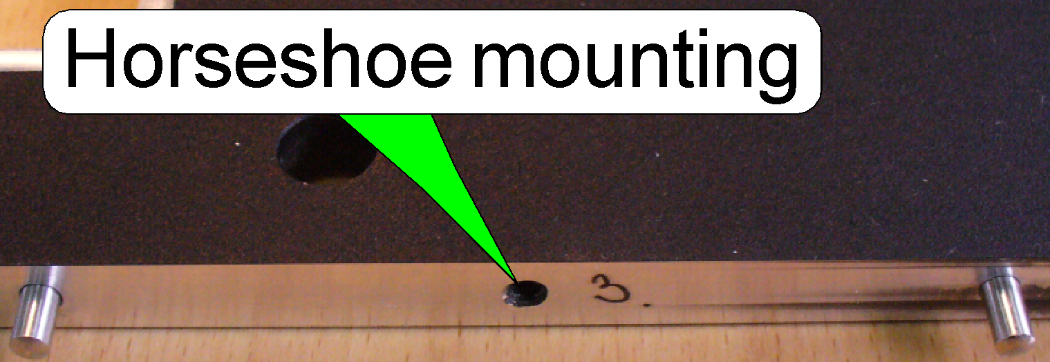 The horseshoe mounting contains two fixing
pins to define the position and a threaded hole for the mounting bolt.
The horseshoe mounting contains two fixing
pins to define the position and a threaded hole for the mounting bolt.
See also: “Preview unit mounting”
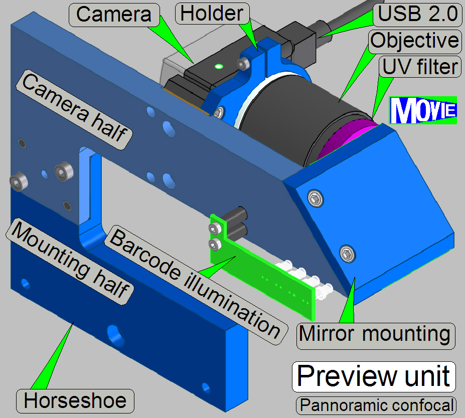
Preview
objective and camera holder
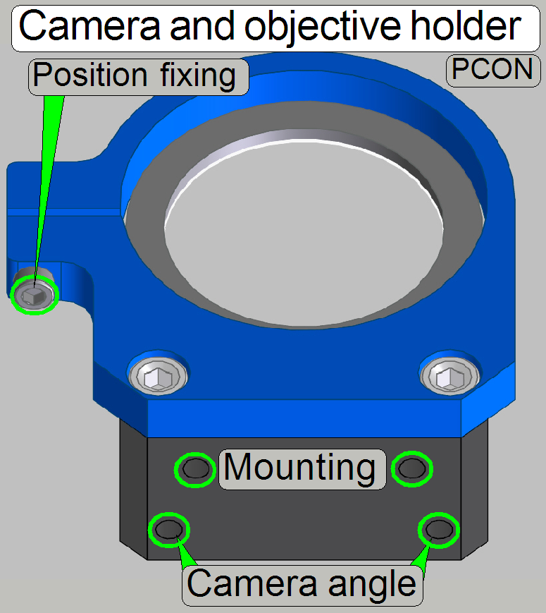 The preview objective and camera holder
allows the adjustment of the preview camera rotation angle in a limited range.
The preview objective and camera holder
allows the adjustment of the preview camera rotation angle in a limited range.
· To
adjust the distance of the objective in relation to the horseshoe, a fitting
plate is used.
To adjust the camera rotation angle:
- Hold the camera on the rear and loosen the position fixing bolt a
little bit until the camera together with the objective becomes barely
rotate-able. Check the tightness of the objective to the camera!
- By loosening one of the “Camera angle” bolts and tightening
carefully the opposite bolt, the rotation angle will be modified.
- If the correct camera rotation angle is found, tighten the
“Position fixing” bolt by pushing the camera to the holder; further
information can be found in the chapter “Adjust the
preview camera rotation angle”.
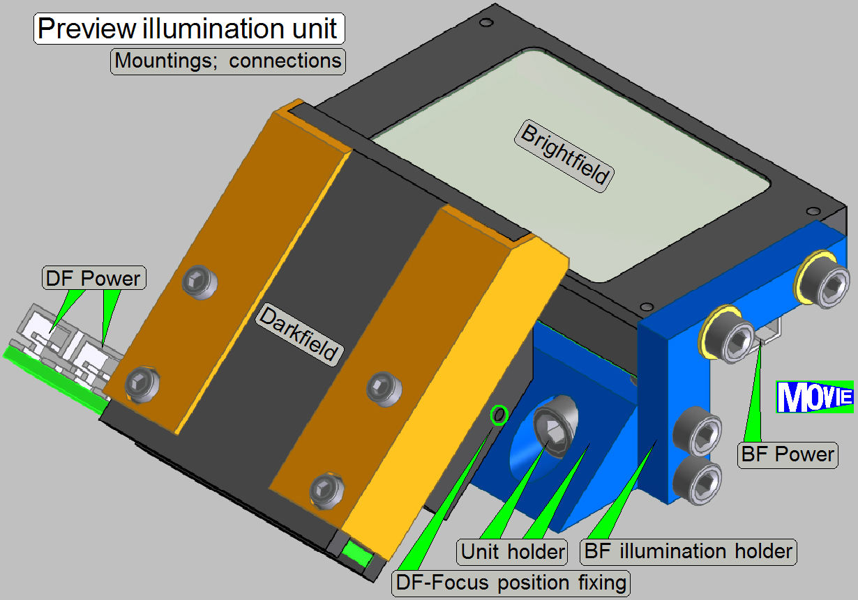 The
preview illumination unit contains the
The
preview illumination unit contains the
· Brightfield
illumination and the
· Darkfield
illumination
See also: “Assembling”
Description see: “Preview illumination unit”
RGB BF Illumination Unit
The unit is used to illuminate the field of view (FOV)
during the brightfield scan session.
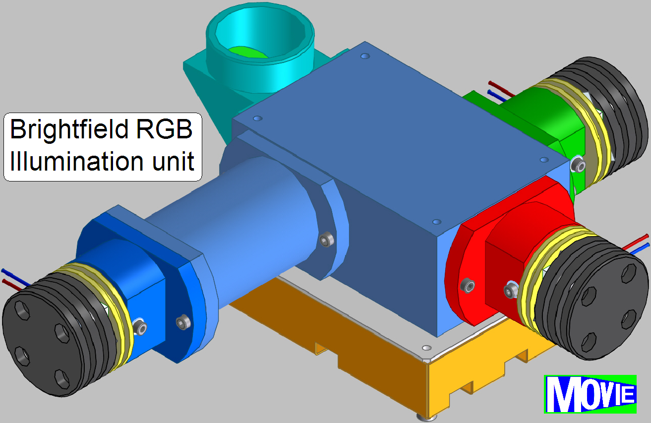
To create color information for the monochrome camera
PCO.edge 5.5MP the FOV of the tissue will be illuminated in the colors red,
green and blue sequentially. The scan camera makes an image of the same FOV
three times; one image of each illumination color. By using the software
coloring method an image of the FOV with high color fidelity is produced.
More detailed information can be found in the chapter
“Optics, illumination” and “Brightfield RGB illumination”
Tray and Slide loader unit
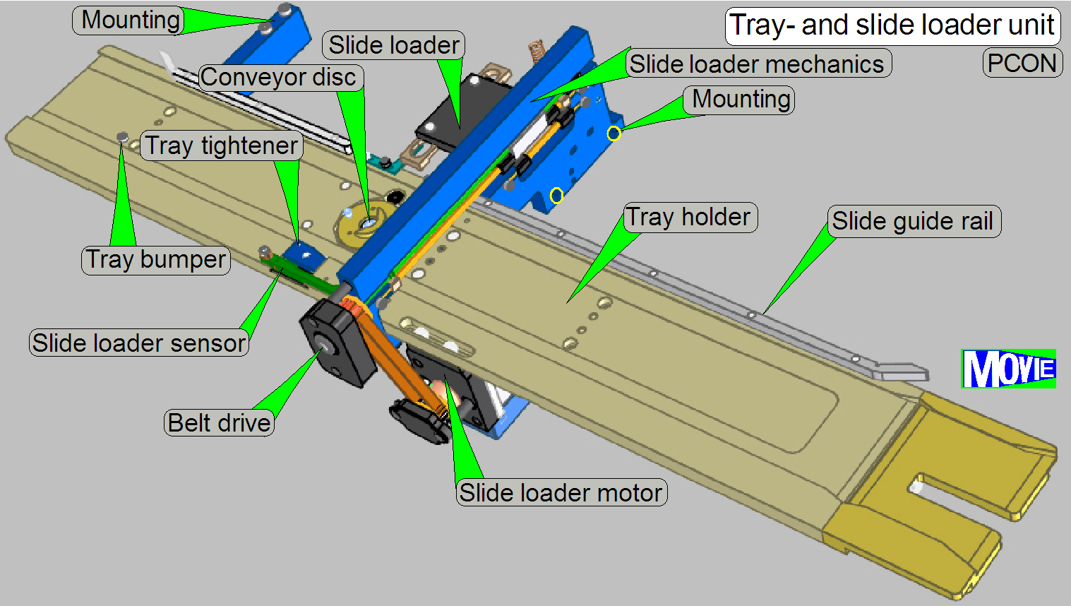 The tray loader unit is used to hold and transport the tray in the tray holder. The tray
itself contains 12 slide bays and is always inserted or removed from the right
side of the scanner. Because the slide is not fixed in the slide bay, the slide
guide rail ensures that the slide has the proper position in the slide bay
during tray insertion and movements. The movement of the tray is realized with
a stepper motor.
The tray loader unit is used to hold and transport the tray in the tray holder. The tray
itself contains 12 slide bays and is always inserted or removed from the right
side of the scanner. Because the slide is not fixed in the slide bay, the slide
guide rail ensures that the slide has the proper position in the slide bay
during tray insertion and movements. The movement of the tray is realized with
a stepper motor.
See also: “Tray and Slide loading”
· The position of
the 60N
· The position of
the Tube Lens is adjustable.
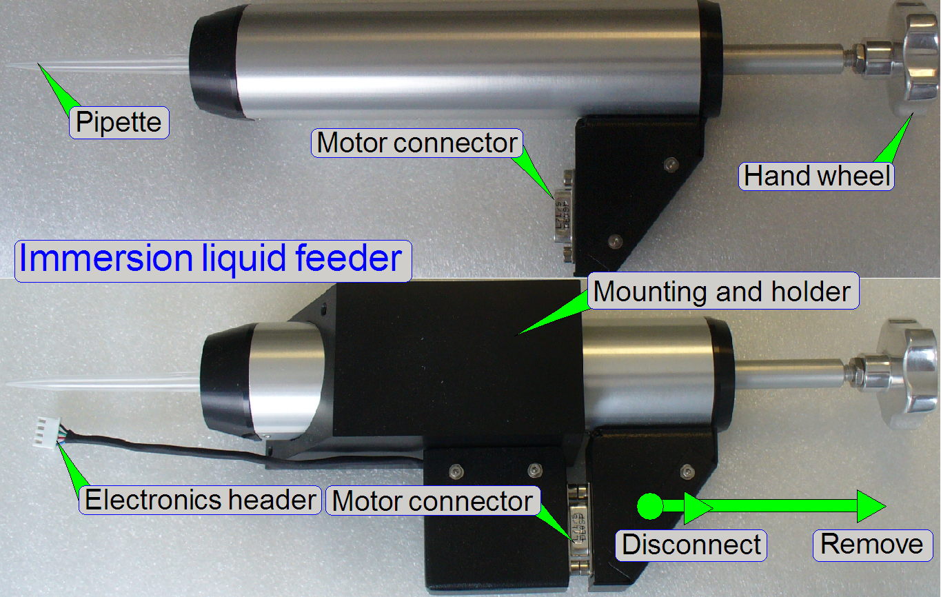 The
immersion liquid feeder is used to spend drops of distilled water onto the
cover slip of the tissue to be scanned with the 40x immersion liquid objective.
The
immersion liquid feeder is used to spend drops of distilled water onto the
cover slip of the tissue to be scanned with the 40x immersion liquid objective.
The distilled water is filled manually into the
pipette and will be spend automatically by the use of the stepper motor before
the scan process starts.
See also: “Optics, Illumination”; “Immersion Liquid
Feeder” and “Power and control”, “Immersion Liquid Feeder”
Remark
· Aligner tools are
removed during normal work!
Objective Changer Unit
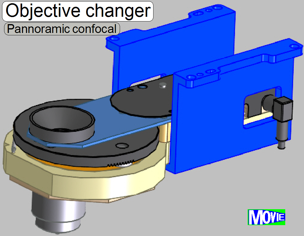 The objective
changer unit allows the consecutive use of 2 different magnifications.
The objective
changer unit allows the consecutive use of 2 different magnifications.
See also: “Objective changer unit”
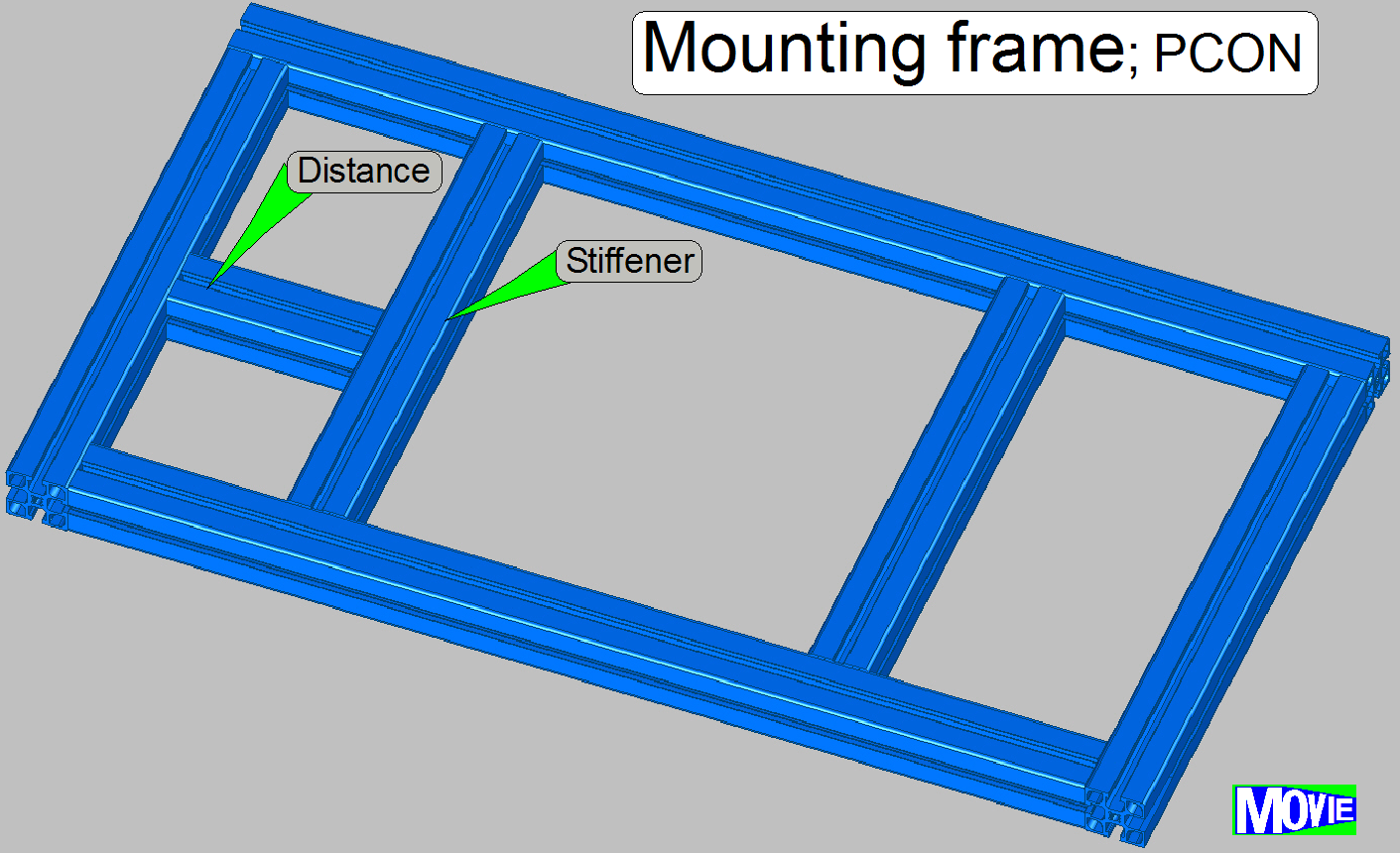 The mounting frame makes the
base of the entire Pannoramic Confocal.
The mounting frame makes the
base of the entire Pannoramic Confocal.
· Rubber feet and
handles are mounted from beneath.
· The base plate and
the power tower are mounted from top.
· Mountings for the
housing are assembled from beside.
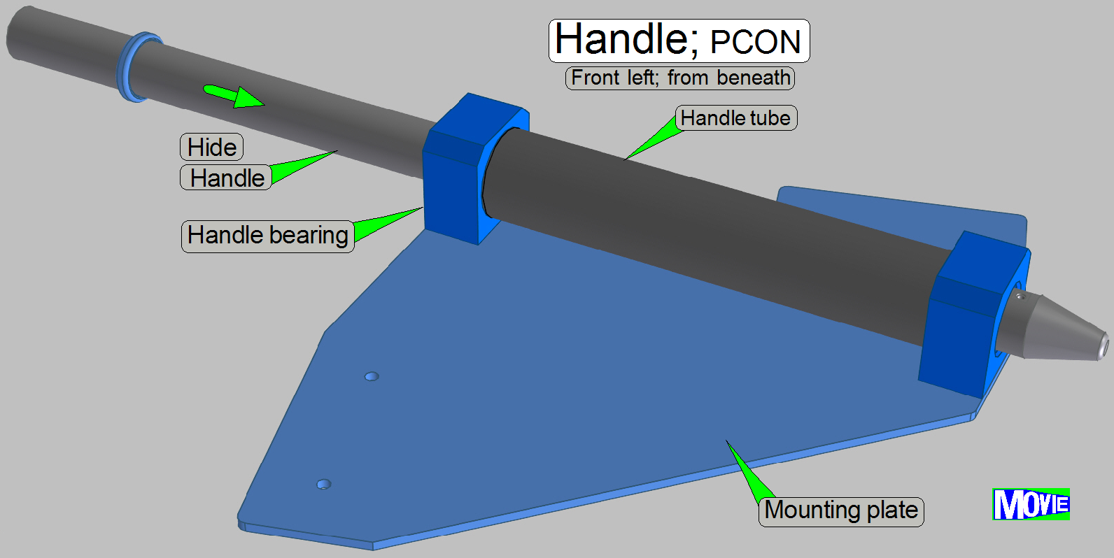
· Four handles allow
the safe movement of the scanner by two persons.
· The handles are
mounted in the corners of the base frame from beneath.
· The mounting
plates in the front of the scanner are different in shape in relation to the
mounting plates on the rear.
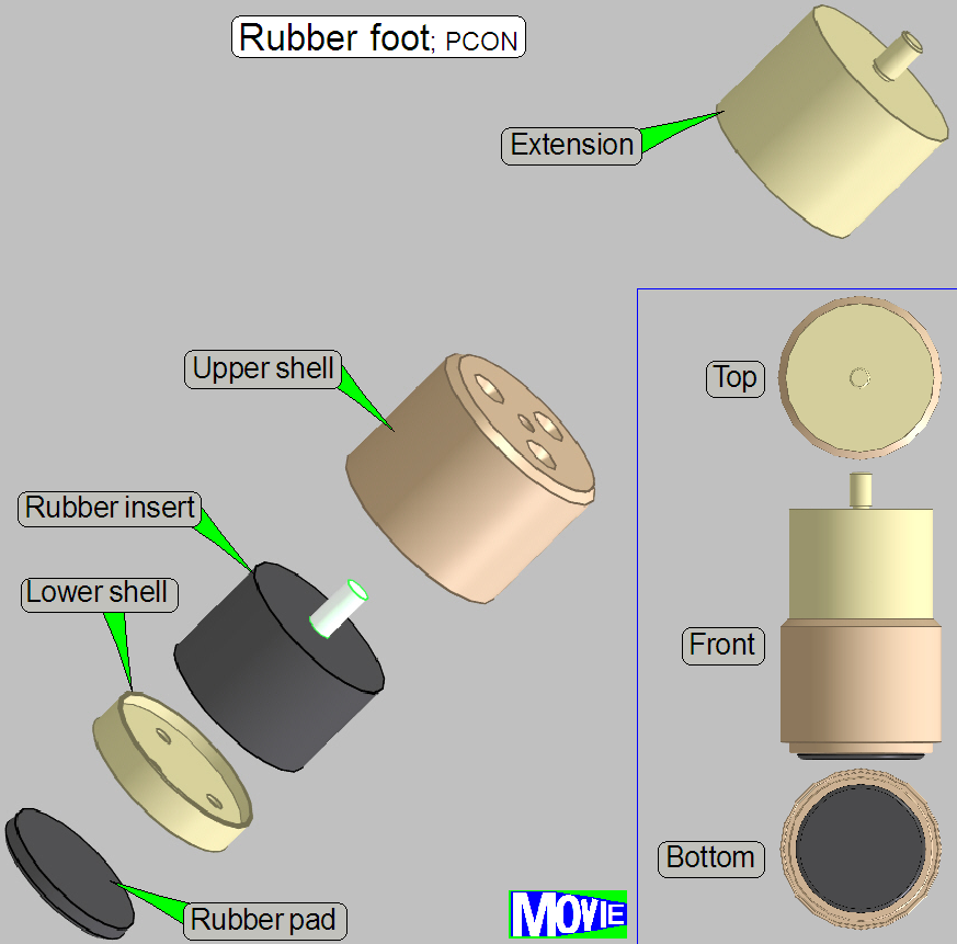 By the use of 6 rubber feet
the scanner contacts the table and the rubber inserts reducing vibration and
noise.
By the use of 6 rubber feet
the scanner contacts the table and the rubber inserts reducing vibration and
noise.