
Copyright
© 2010 – 2018 3DHISTECH LTD all rights reserved.
CONFIDENTIAL!
 The
following contents list contain all the links to the chapters about the
housing, construction, mechanical, optical and electronics parts and components
as well as adjustment procedures used and done in the scanners.
The
following contents list contain all the links to the chapters about the
housing, construction, mechanical, optical and electronics parts and components
as well as adjustment procedures used and done in the scanners.
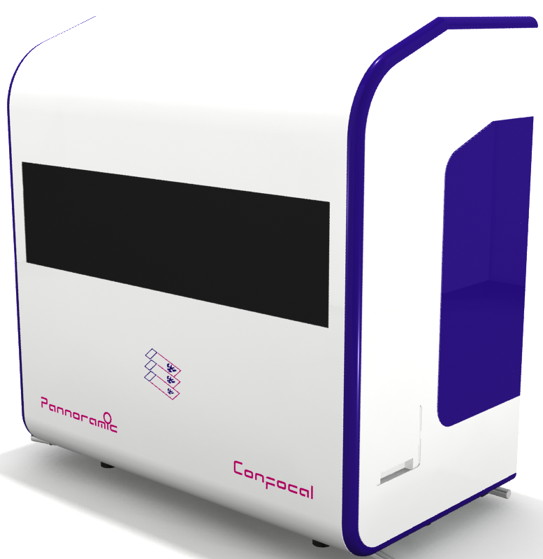
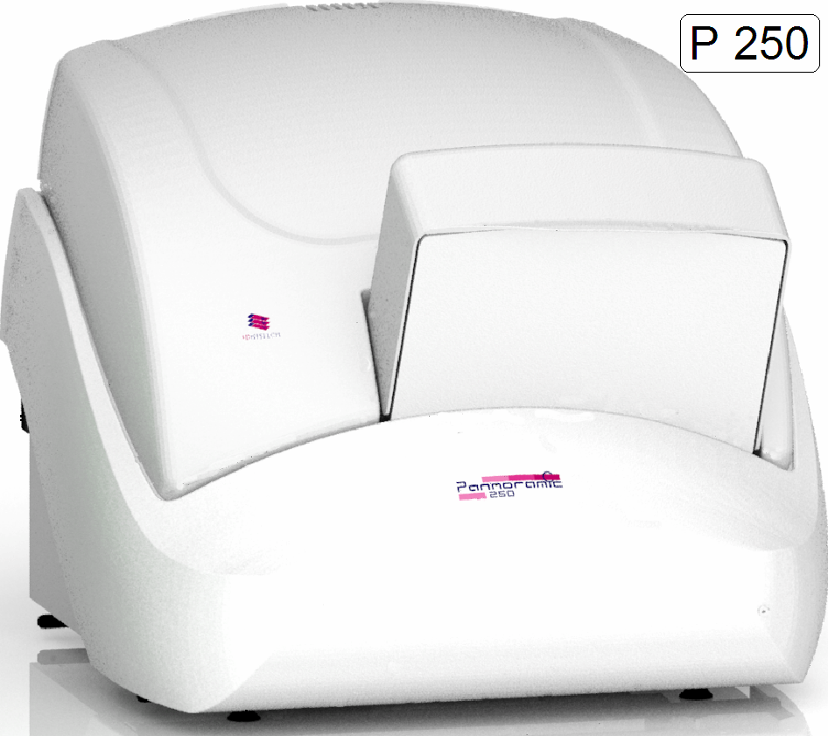
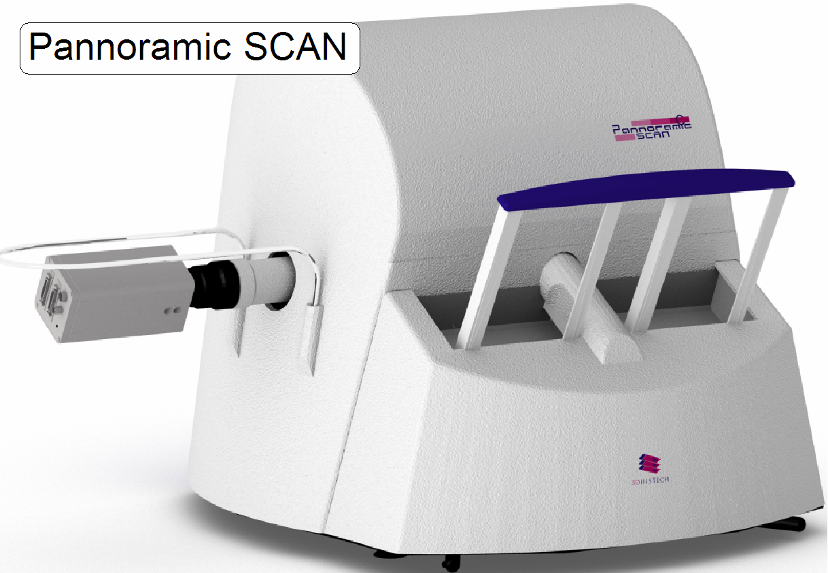
· Pannoramic
Confocal, P250, SCAN,
· Images
with blue frame contain a link to the relevant chapter.
The following contents may be used as an alternative
to the tree structure of the manual on Tablet and Android, if the browser does
not display the navigation window correctly or otherwise correct links will not
work.
Select a chapter
Common articles
for all scanners

Contents;
summary (this file)
Precautions;
summary PCON; P250; S_M_D

Handling of extension
cards and electronics devices
Tools and requirements; PCON; P250;
S_M_D
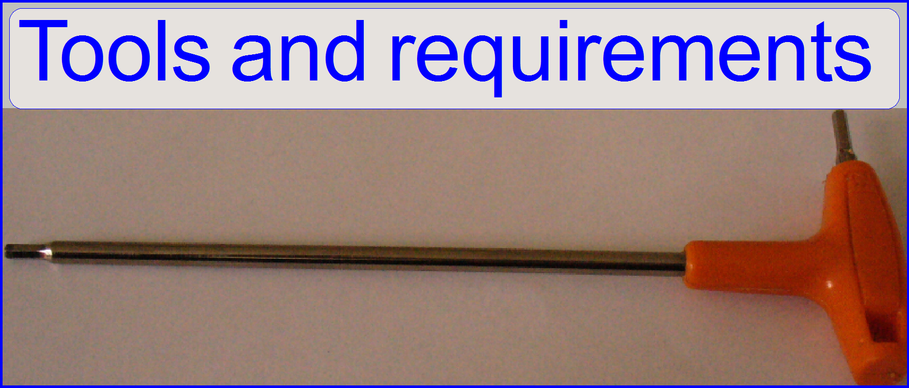
Tools used to
cleaning optical surfaces
Slide
scanner service PCON; P250;
S_M_D
Section [Microscope] of MicroscopeConfiguration.ini
 PCON; P250; S_M_D
… Check …
… Define …
… Exchange (spare)
parts and units
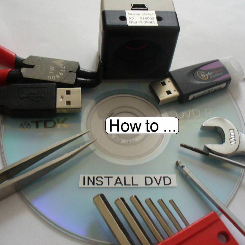
… Install software
and drivers
… Upgrade units
and components

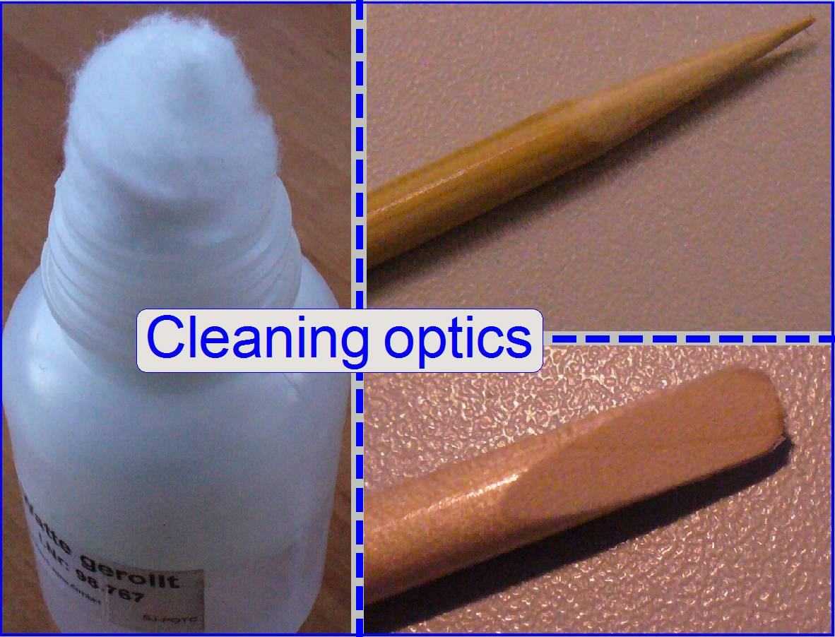 Cleaning optics ; All scanners
Precautions to avoid
cleaning of optical components
Tools and materials used to
cleaning optics
Decide, where the
dust can be found
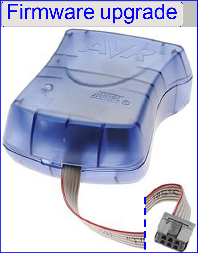 Step motor firmware upgrade; S_M_D
Start the Atmel
programmer software
Install
“Atmel AVR Tools” and “AVR Studio 4”
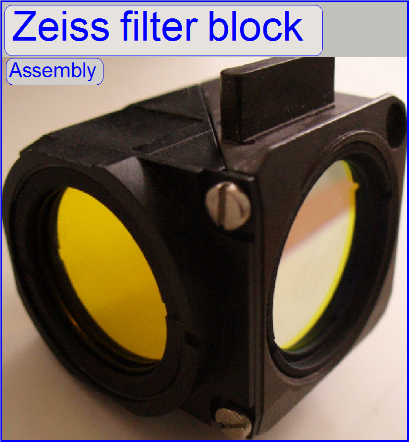
FL filter block
assembling S_M_P250
|
Addresses of scanner
units |
||
|
Unit |
Address |
Type |
|
X-Y-Z
control |
00 |
C_P |
|
USB-controller |
01 |
All |
|
DC-controller |
02 |
P_S_M_D
|
|
X-motor |
03 |
S_M_D |
|
Y-motor |
04 |
S_M_D |
|
Z-motor |
05 |
S_M_D |
|
Turret
unit |
06 |
S_M_P |
|
Tray
loader motor |
07 |
M_C |
|
Slide
loader motor |
08 |
M_C |
|
Objective
changer |
09 |
C_P_S_M
|
|
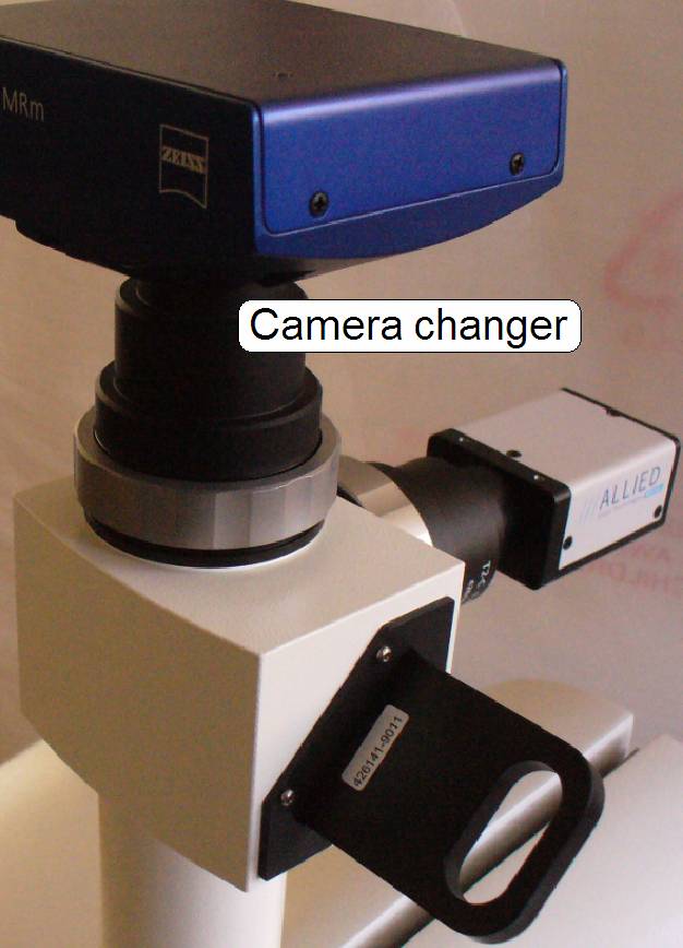
Camera
changer |
10 |
P |
|
RGB
illumination |
11 |
C |
|
Tilting
unit |
12 |
C |
|
Immersion
liquid unit |
13 |
C |
|
Mechanical
shutter |
14 |
C |
|
Switch
board |
15 |
C_P |
|
Legend:
C=Confocal; P=P250; S=SCAN; M= |
||
Define Address of unit All scanners
FOV and Preview All scanners
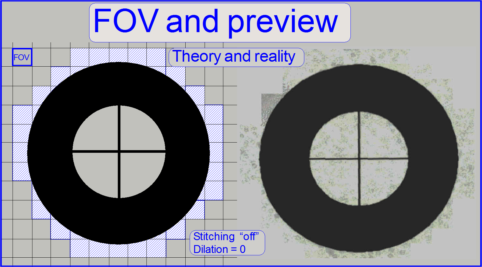
Influence of the
camera adapter
Pixel position
and corrections
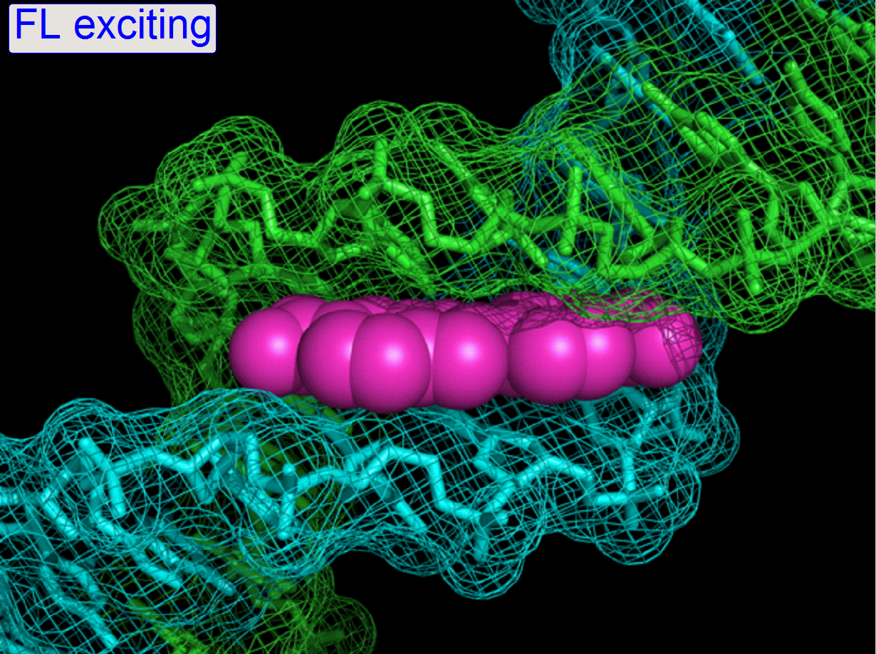 Fluorescent
exciting All FL scanners
Fluorescent
exciting All FL scanners
Characteristics
of camera sensor
Principles
of exciting and imaging


· All
videos are created with a resolution of full HD 1080p (1920x1080pixels).
· If
the speed of the internet connection is slow, the opened video may show an
erratically (jerkily) flow (the video is not played continuously). Please load
down it and play the video in the memory!
· A
second reason might be the processor speed and available memory capacity
because the video file will be decompressed before playing.
Please open the folder “Video”
and select the file of interest!

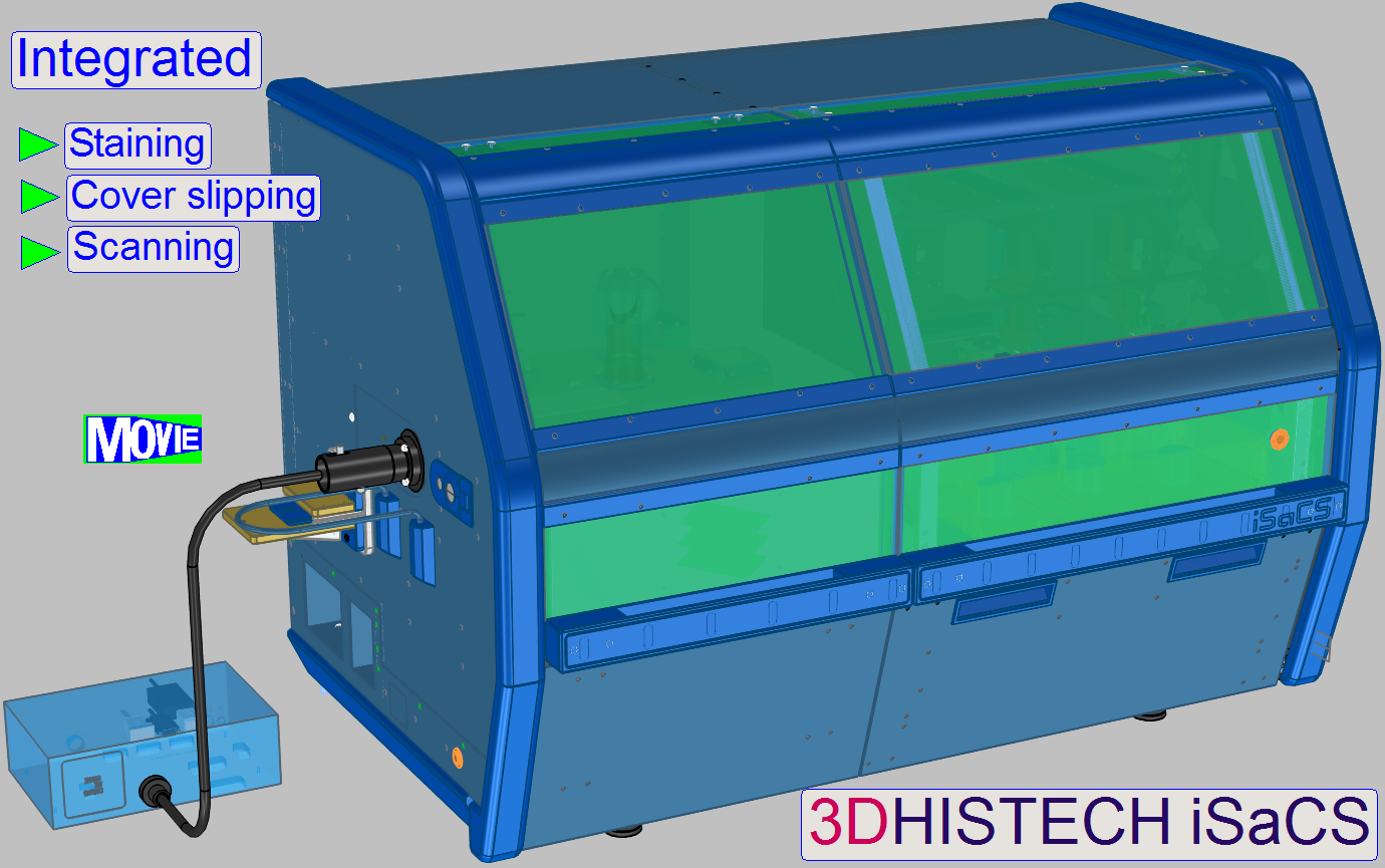
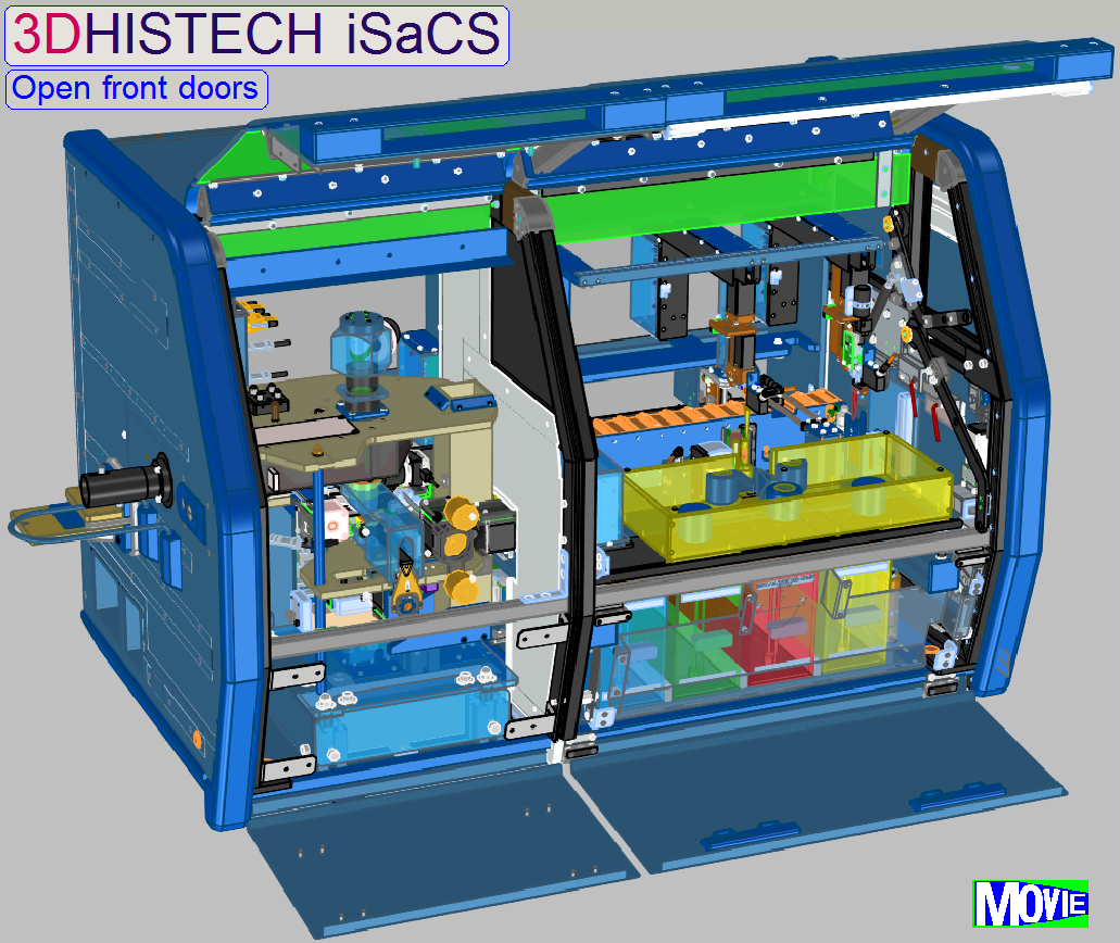
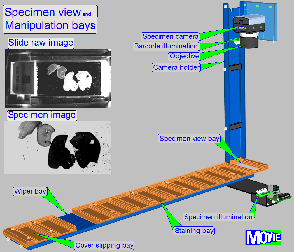
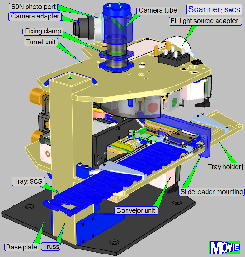
Scanner; iSaCS
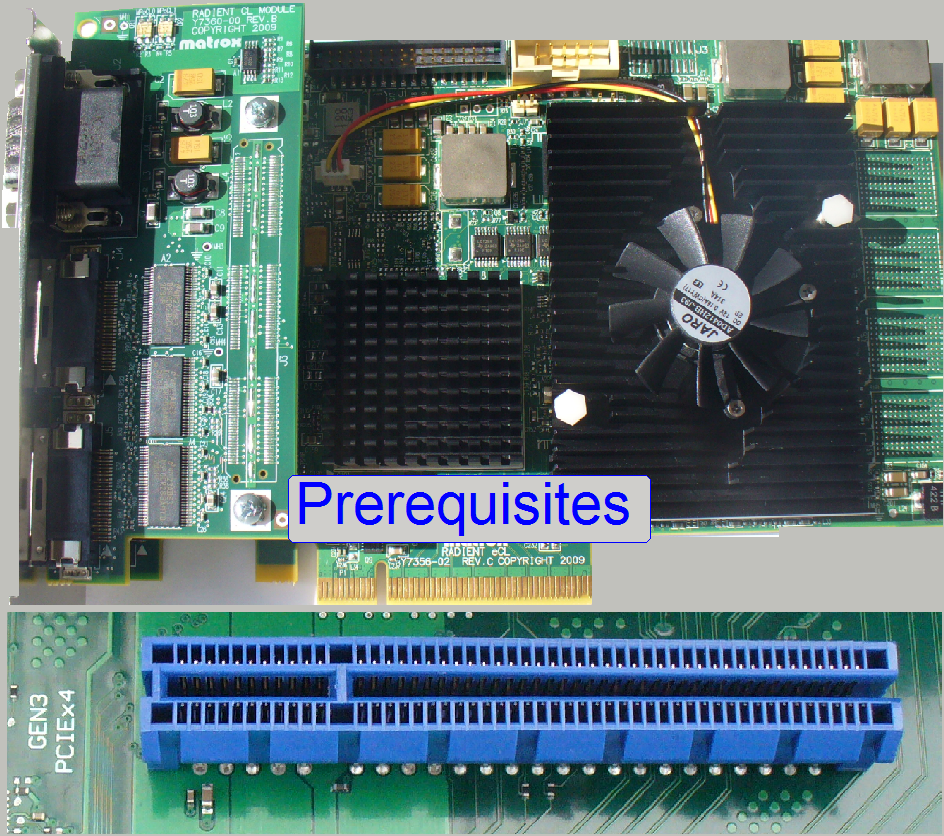

Prerequisites for Pannoramic scanners; PCON; P250; S_M_D
Hardware
conditions and cabling
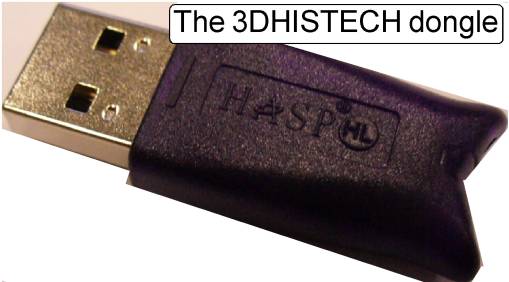
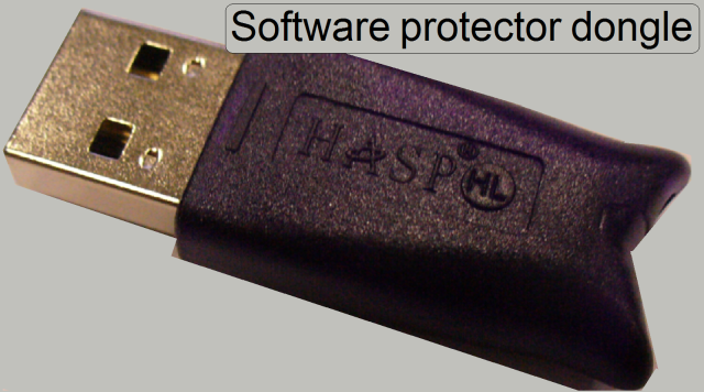
Dongles PCON; P250; S_M_D

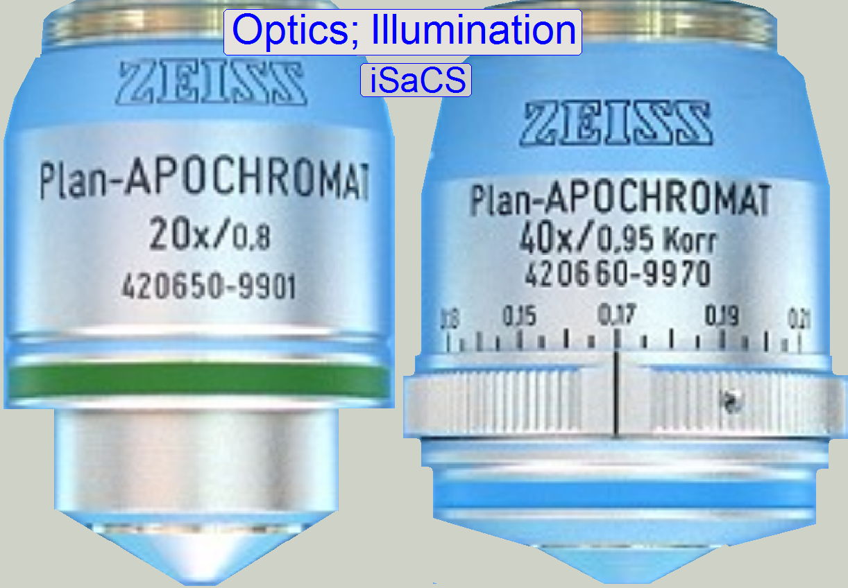
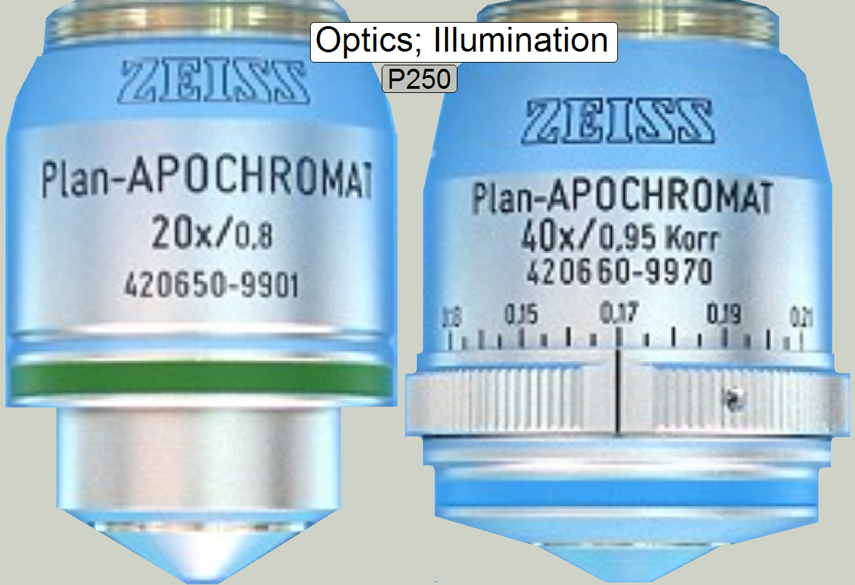
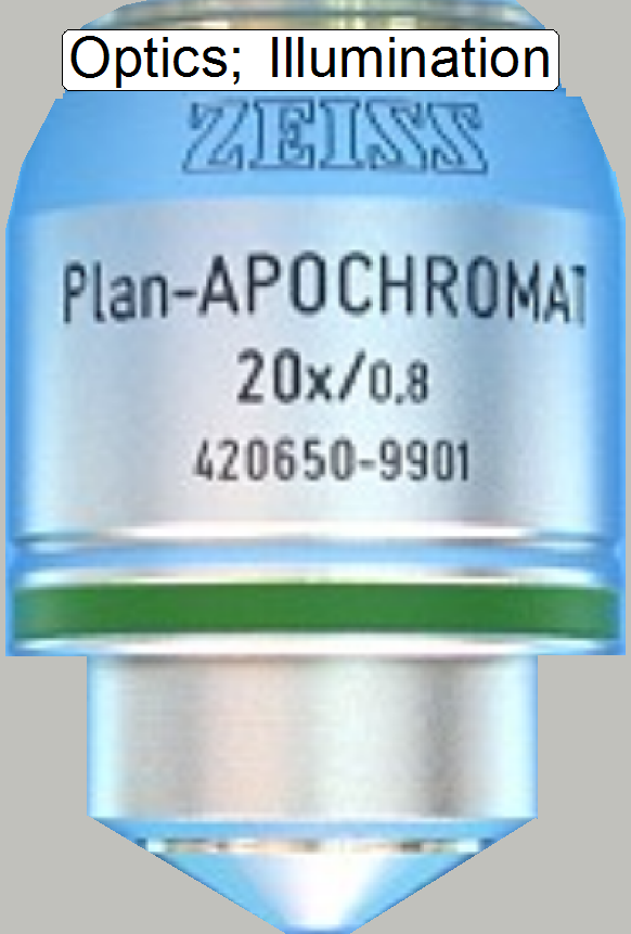
Optics and illumination; PCON
Brightfield
illuminated optical path
Configure
light sources and units
Brightfield
RGB illumination unit
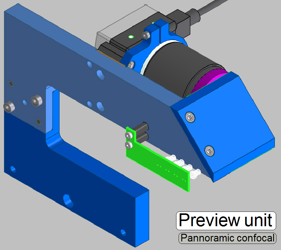
Preview; PCON
Focus unit
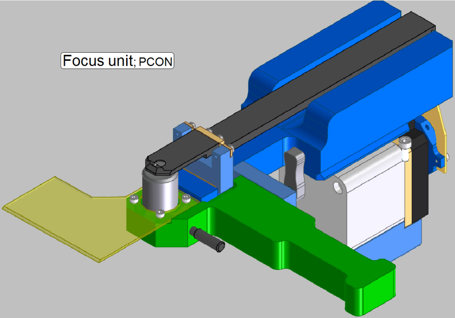
Functional
overview of the focus unit
Components and construction
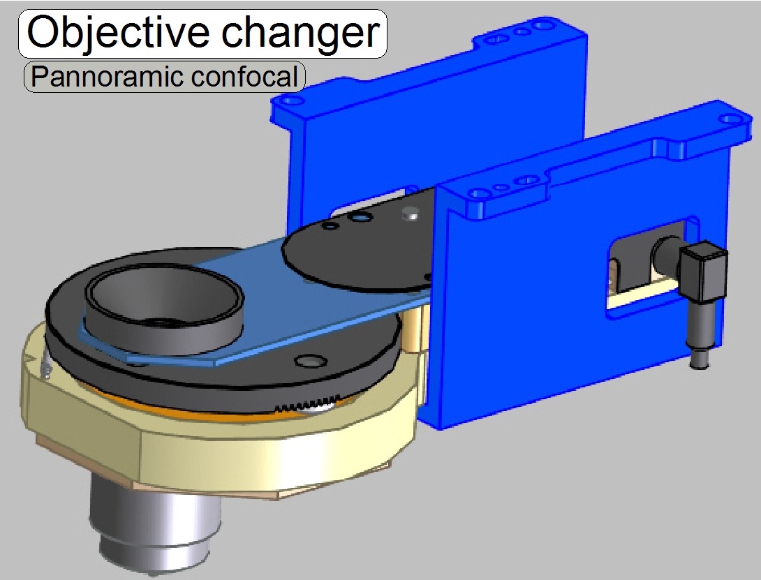
Objective changer;
PCON
- General
- Configure
- Working principle
- Change the objective (Software)
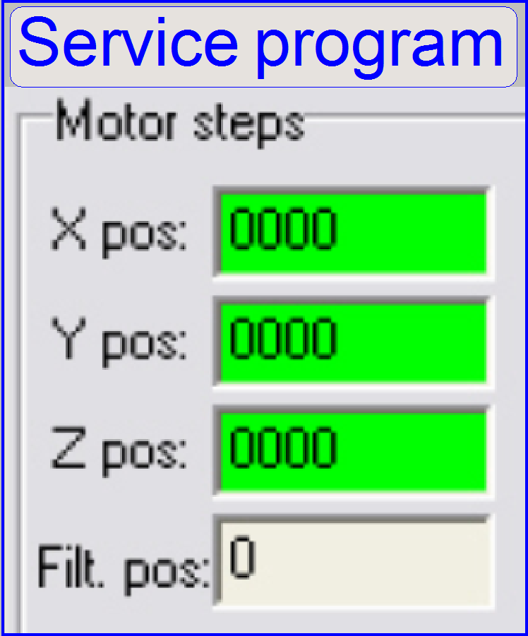
- Use
the service program
- Components,
construction
- Dismount
- Assembling
- Adjustments
- Setup
implemented objectives
- Align
the Objective position
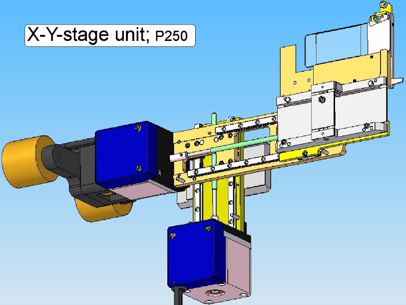
X- and Y-stage unit;
PCON
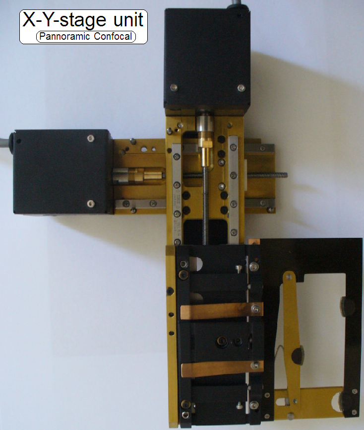
Functional
overview of the X-Y-Stage
Check the
hysteresis in Y-direction
Dismount /
mount the carriage drive unit
Tray and slide loader; PCON
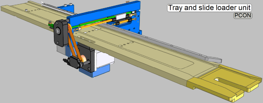
Setup
and adjustment procedures
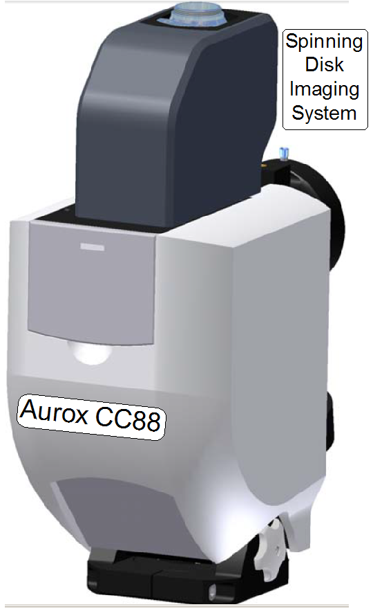
Confocal unit
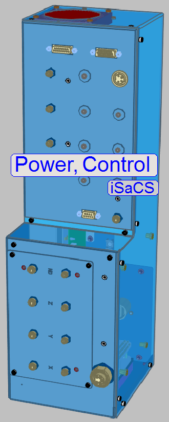
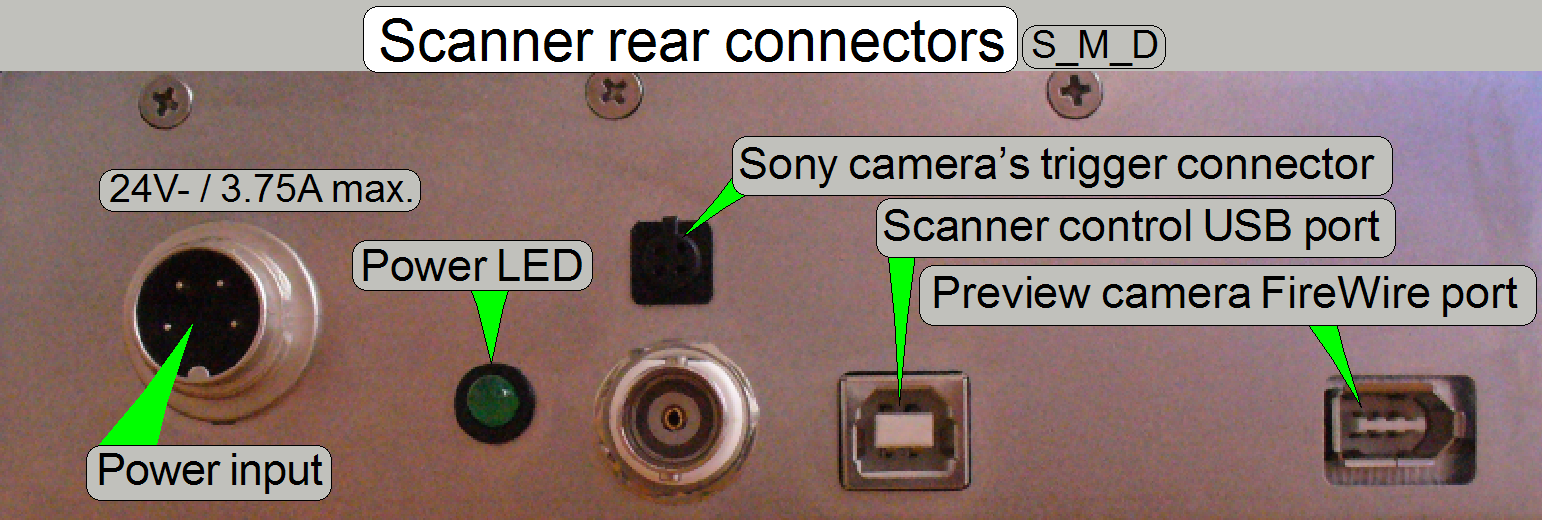
Power and control;
PCON
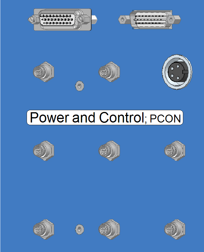
Power input
connector and main switch
Power
distribution and switch board
USB Controller with EEPROM
Stepper motors
with control electronics mounted
Stepper
motors without control electronics mounted

Differences
between P250BF and P250FL
Prerequisites for
Pannoramic scanners; PCON; P250; S_M_D
Hardware
conditions and cabling
Dongles PCON; P250; S_M_D

Optics and illumination; P250
Neutral density (ND) filter unit
Brightfield scan (main) camera
Check the optical path adjustments
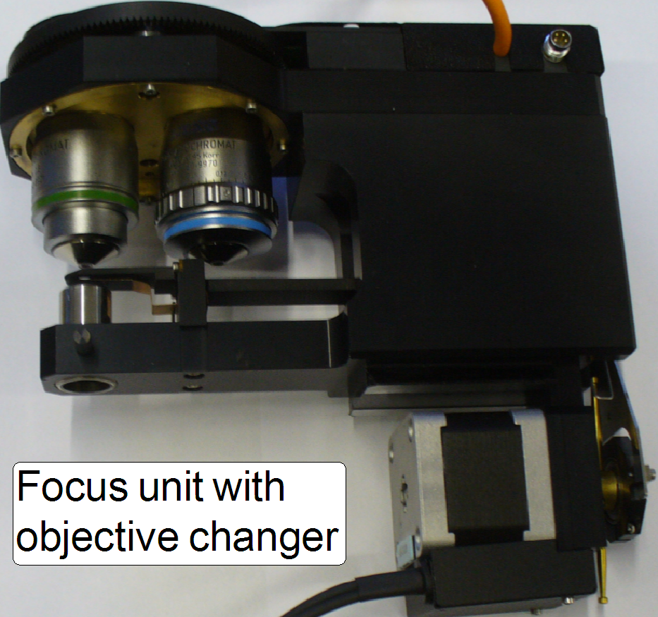 Focus unit with objective changer
Functional
overview of the focus unit
Components and construction
Adjustments
of the focus part and shutter mechanics
Adjustments of
the objective changer part
Dismount or
mount the focus unit with objective changer
Setup and
define the implemented objectives
Functional
overview of X-Y-Stage
Check the
hysteresis in Y-direction
Dismount őr
mount Carriage drive unit

Functional
overview of Camera changer unit
Components
and construction of Camera changer unit
Dismount
/ mount Camera changer unit
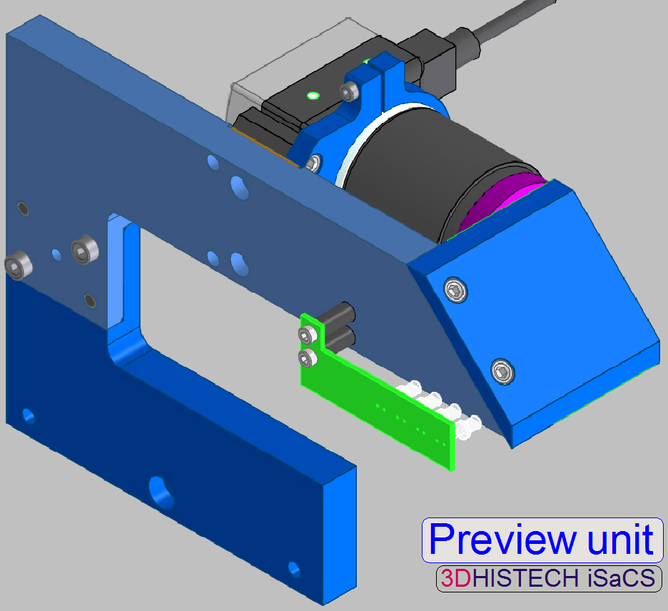
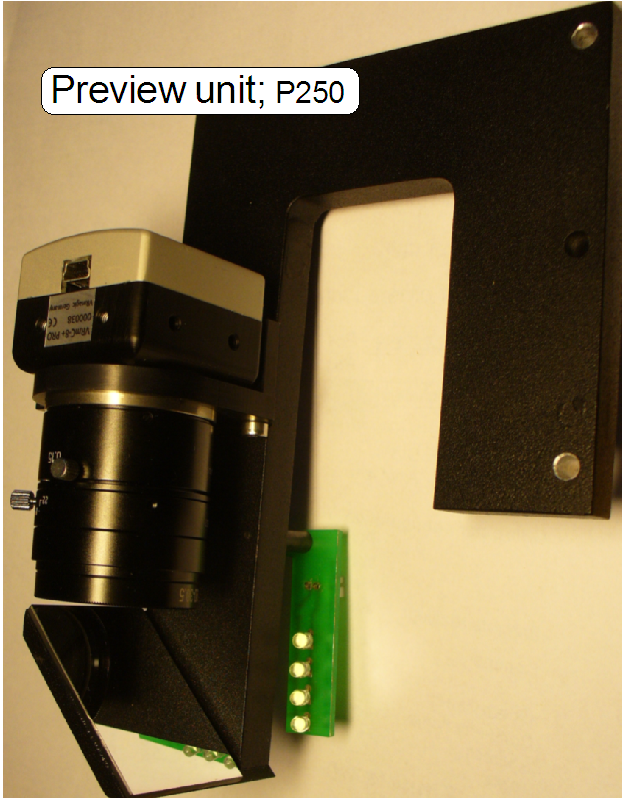 Components of the preview
unit
Components of the preview
unit
Preview objective and camera holder
Adjustment
procedures of the preview unit
Steps of the preview calibration procedure
Adjust
the pixel of the preview camera to the field of view of Scan camera
Darkfield preview
calibration procedure
Prerequisites
for a successful darkfield preview calibration procedure
Calibrate the
darkfield preview manually
Principle of the darkfield calibration
Execute the darkfield calibration
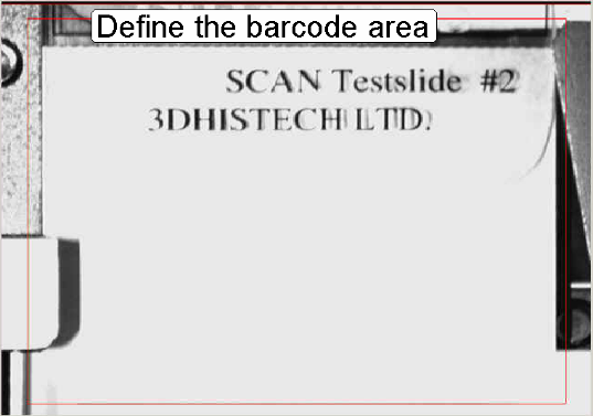
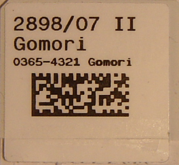
Barcode reading and adjustments
Adjust the barcode
illumination
Check barcode reading with
different barcodes and types
Magazine unit and slide handling;
P250
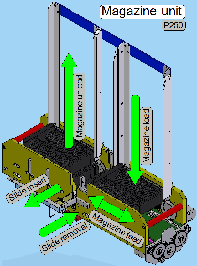
Enhancements in the magazine unit of
the P250
Components
and mechanical construction
Remove
or mount the magazine unit
Components
and mechanical construction of Slide loader
Adjust
the magazine load mechanics
Slide
insert / removal (software)
Define
and adjust Slide insert and removal positions
List
of Parameters and explanation
Power
and control; P250
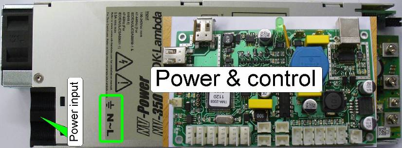
Power input
connector and main switch
Emergency power off
(standby) switch
Power
distribution & switch board
USB Controller with
EEPROM
X-Y-Z-ND-motor and
Flash light control
Stepper motors
with control electronics
Stepper
motors without control electronics
Temperature
and fan control logic
Reflector turret
unit; belt
Configure the belt driven reflector turret unit
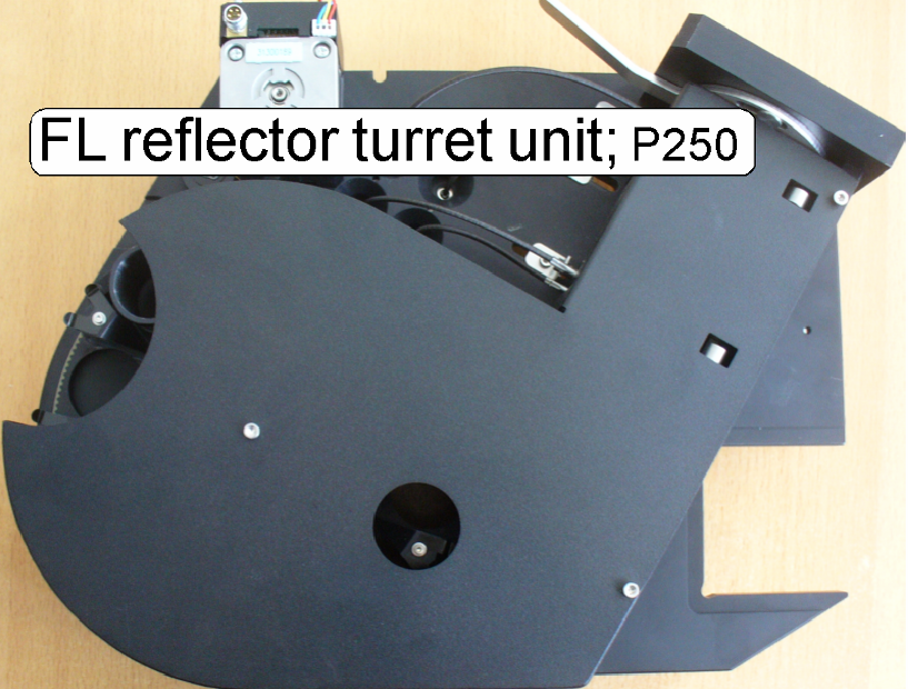 Functional overview of the
reflector turret unit
Functional overview of the
reflector turret unit
Construction
of Fluorescent illumination and image path
Mechanical components and construction
·
Stepper motor and the belt wheel
·
Diaphragm
position adjustment tools
·
Remove / mount FL
reflector turret unit
Optical components
·
Light source
adapter and mounting
·
EPI-fluorescent
illumination unit
·
Mirror
Adjustment techniques / checks
·
Tools, used for the
adjustments
·
Check / adjust
the tightness of the belt
·
Adjust the
external sensor position
·
Find the first
filter position
·
Check
correctness of the filter fixing in the filter positions

Optics and illumination; S_M_D
 Optics_Illumination.htmComponents and construction
Illumination mirror;
MIDI, DESK
Brightfield illumination
adjustment parts
Adjust Uniformity of the
illumination with Look up table
Check the optical path
adjustments
 Camera changer (Double
adapter 60N)
Camera changer (Double
adapter 60N)
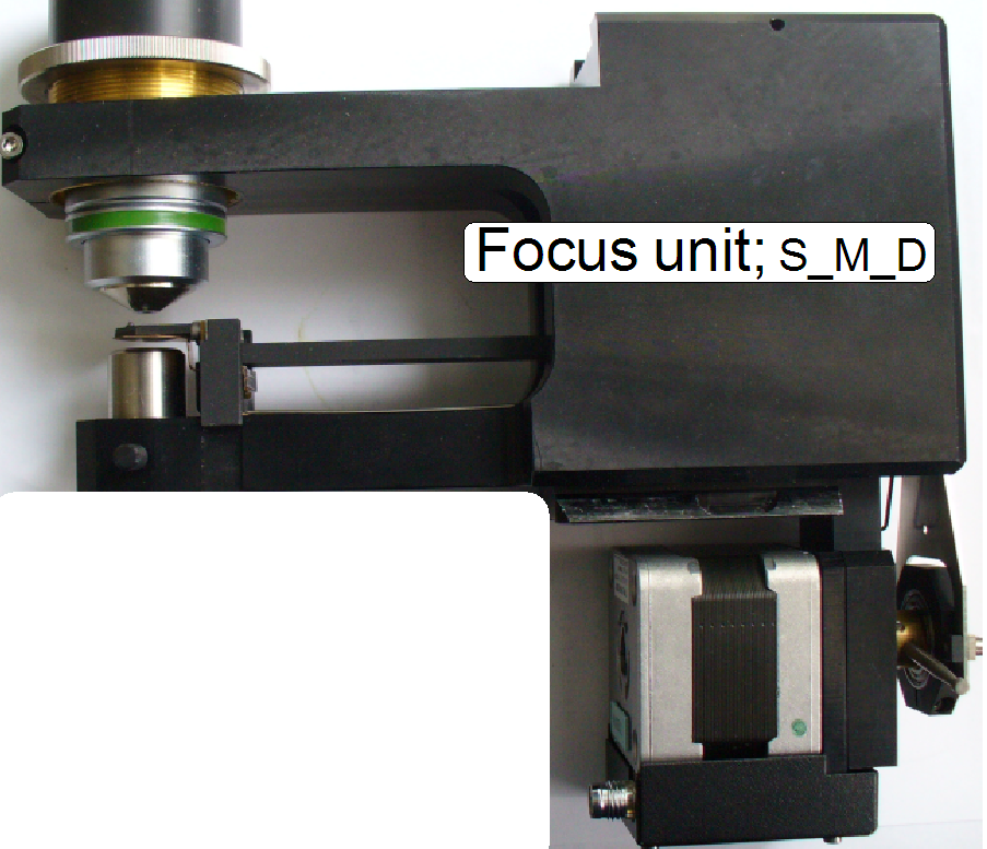 Focus unit; S_M_D
Components and mechanical
construction
Find the hardware limits
for Focus unit
Check or adjust the nominal
focus positions
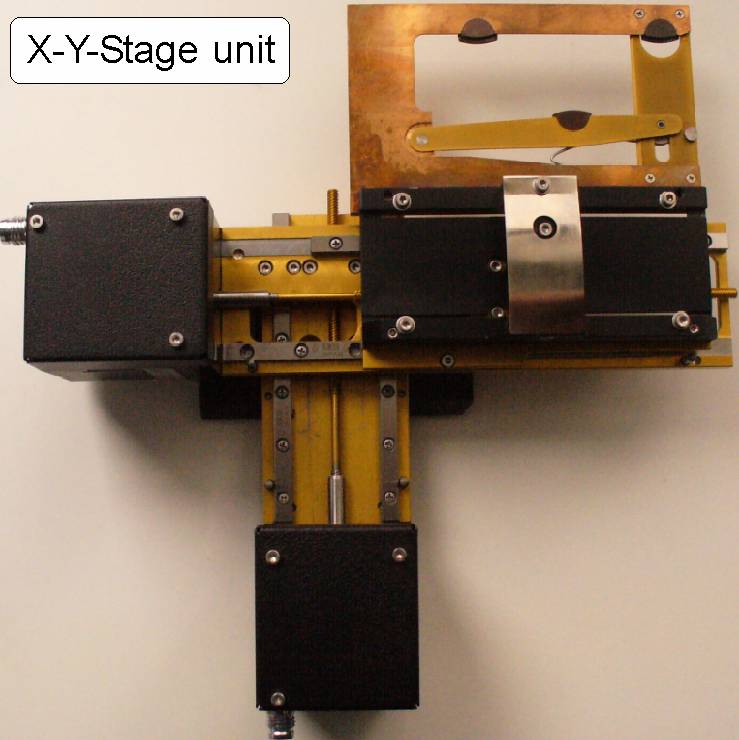
X-Y-Stage unit; S_M_D
Functional overview of X-Y-Stage
Check the maximal hysteresis in
Y-direction
Transport spindle; Multi (4)
thread spindle
Transport- and counter nut with
spring
USB and DC control; S_M_D
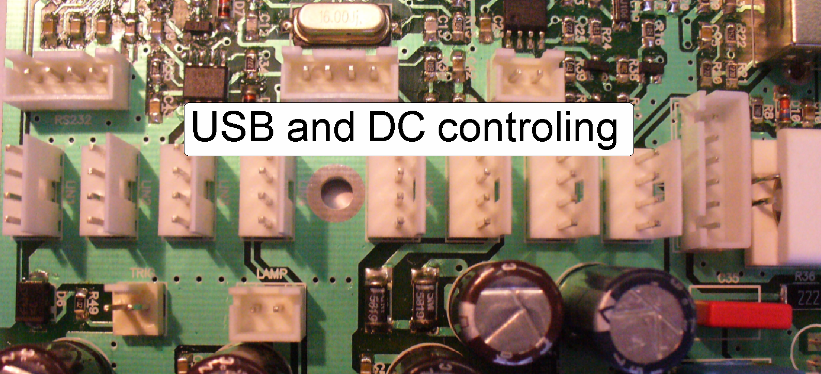
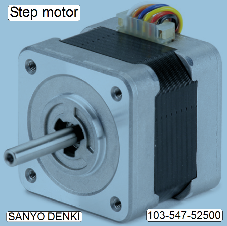
Construction of the
stepper motor
Preview unit;
S_M_D
Barcode
reading and adjustments; S_M_D
System technique for panoramic scanners
· This
chapter was replaced; please refer to
 Prerequisites for
Pannoramic scanners; PCON; P250; S_M_D
Prerequisites for
Pannoramic scanners; PCON; P250; S_M_D
Hardware
conditions and cabling


Prepare SCAN and Cover
for shipping
Reflector
turret unit; Gear
Construction
of the fluorescent illumination and image path
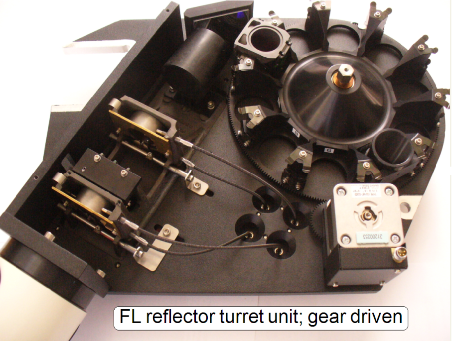 Mechanical components and construction
·
Diaphragm
position adjustment tools
·
Remove or mount the FL
reflector turret unit
Optical components
·
Light source adapter
and mounting
·
EPI-fluorescent
illumination unit
·
Mirror
Adjustments and checks
·
Tools, used for the
adjustments
·
Check the
correctness of the filter fixing in the filter positions
Magazine unit and slide handling
Functional overview of the
Magazine unit
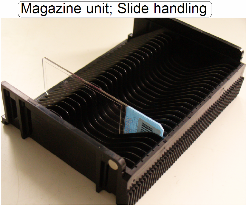
Components and mechanical
construction of the magazine unit
Adjust the magazine load
mechanics
Components and mechanical
construction of Slide loader
To move Slide loader
moveable part manually
To adjust the inner finger
vertical position
Check the function of Slide
loader sensors
Slide loader parts for slide
handling
Define and adjust Slide
insert and removal positions
Adjust the position of the
magnet disc
Adjust the position of the
magazine unit
Adjust Slide insert position
in X-direction
Adjust the final insert
position in Y-direction
Mistakes and abnormal /
faulty behavior during slide insertion
Mistakes and abnormal /
faulty behavior during slide removal
List of Parameters and
explanation
Remove the magazine unit from
Scanner
Please refer also to


Please refer also to
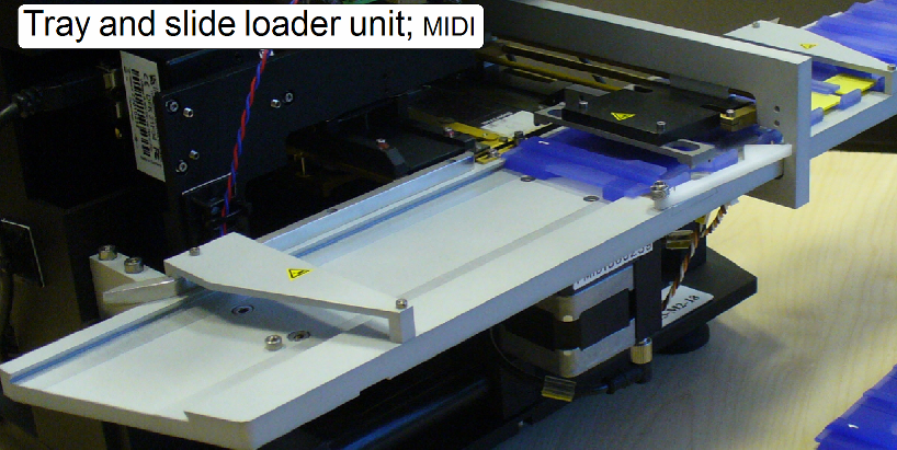 Functional overview of the tray-
and slide loader unit
Functional overview of the tray-
and slide loader unit
Slide loader and support
plate mechanics
Setup and adjustment
procedures
The adjustments are done
in the following sequence
Dismount / mount the
tray- and slide loader unit
Reflector
turret unit; Gear
Construction
of the fluorescent illumination and image path
Mechanical components and construction
·
Diaphragm
position adjustment tools
·
Remove or mount the FL
reflector turret unit
Optical components
·
Light source adapter
and mounting
·
EPI-fluorescent
illumination unit
·
Mirror
Adjustments and checks
·
Tools, used for the
adjustments
·
Check the
correctness of the filter fixing in the filter positions

To adjust the door sensor
position
Adjust Supporter on Left side of
Specimen holder
Check the gap between slide
leader and Specimen holder
Please refer also to