Housing, construction; S_M_D
For technicians!
This chapter handles components of the
housing and mechanical construction of the scanners Pannoramic SCAN, Pannoramic
MIDI and Pannoramic DESK (S_M_D). Because the optics and electronics components
of the scanners are very similar and often identical, these scanners are
described together and differences are named explicitly.
· All the components are explained in the part of the
SCAN, in the descriptions of the

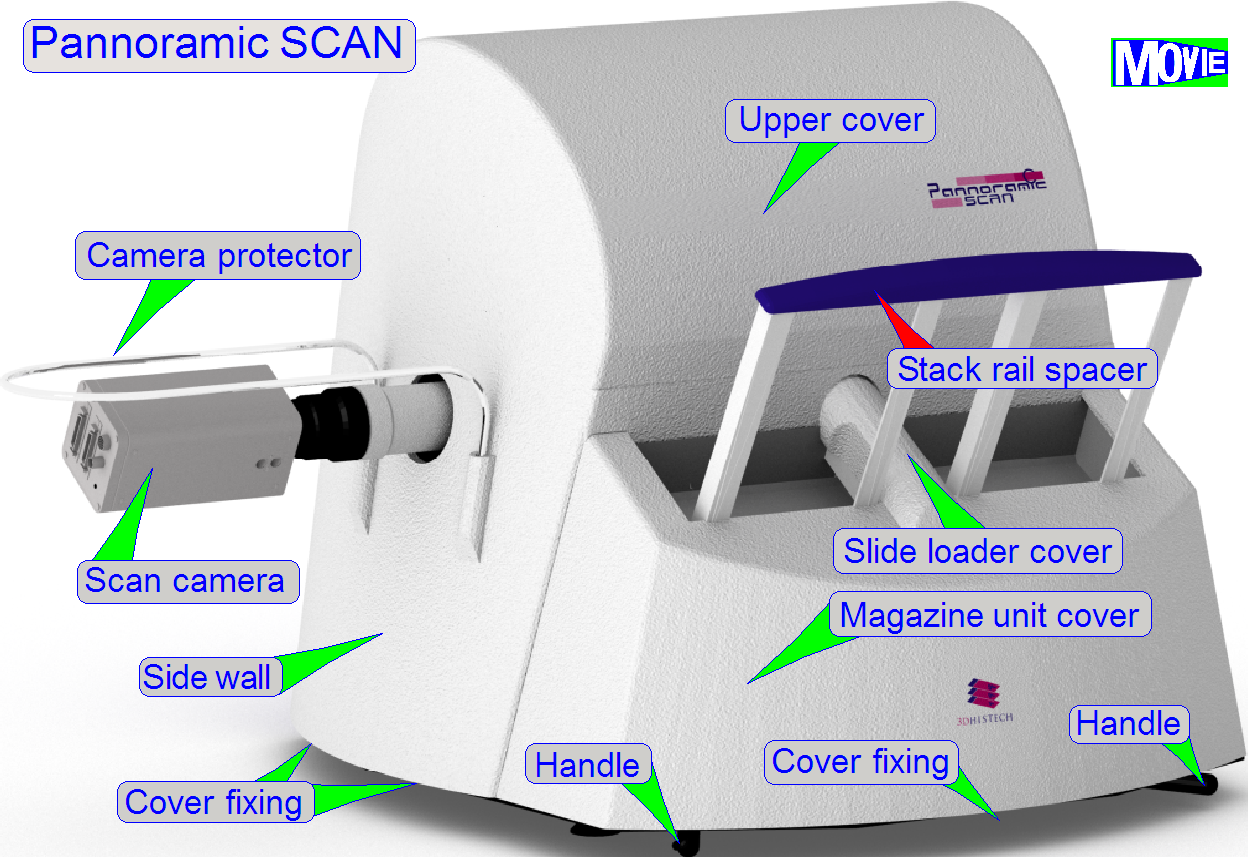
The housing of the Pannoramic
SCAN scanner consists of:
·
The
base plate (with 4 rubber feet, 4 handles for transport, 4 cover fixings to fix the upper
housing and 1 cover fixing to fix the magazine unit cover)
·
The side
wall (its position can be adjusted in relation to the upper housing)
·
The upper housing with the mounting of the camera
protector
·
The magazine unit cover with slide loader cover (these
can not be separated)
·
The
back wall (not shown) is mounted with 3 washers and 3 bolts to the base plate
·
The
input stack cover and the output stack cover (not shown)
Its task is to join the stack
rails, fixing their positions in relation to each other and improves the
stability of the magazine loading process.

The stability of the stack rail spacer is not designed for
any movements of the scanner; it is not a handle!
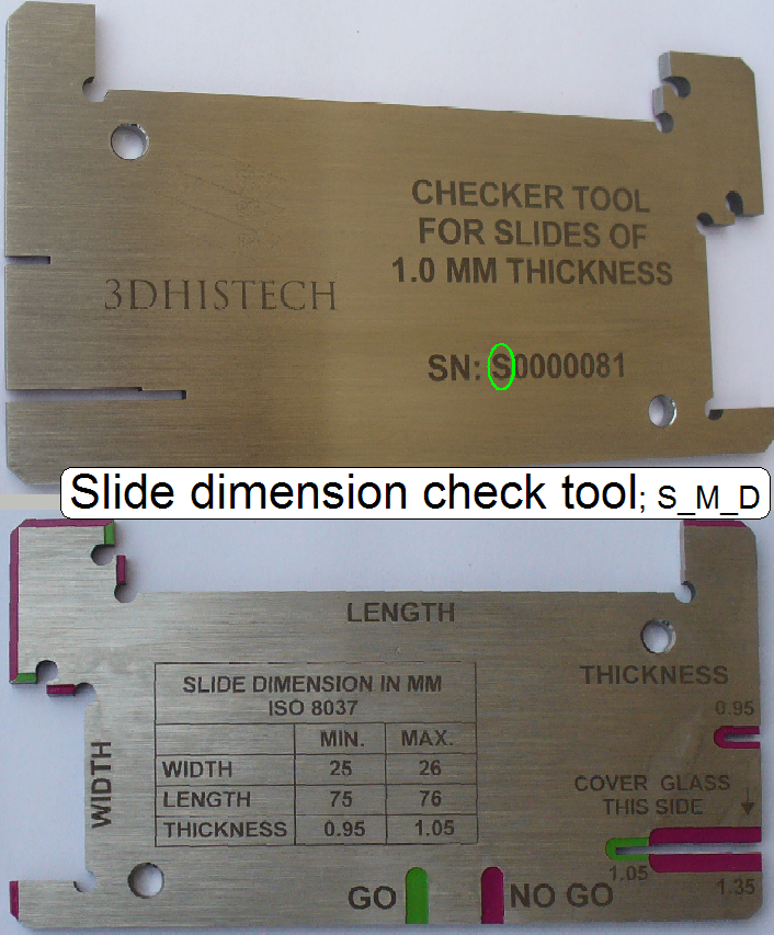 The allowed slide dimensions are:
Length: 75.00
to
Width: 25.00
to
Thickness: 00.95
to
Since January
- If the first character of the serial number is an
“S” the tool is used to check the slide dimensions
of the scanners “SCAN, “
- If the first character of the serial number is a “P” the tool is used to check the
slide dimensions of the scanner “P250”.
·
Please check
the slide dimensions before filling the magazine with slides!
·
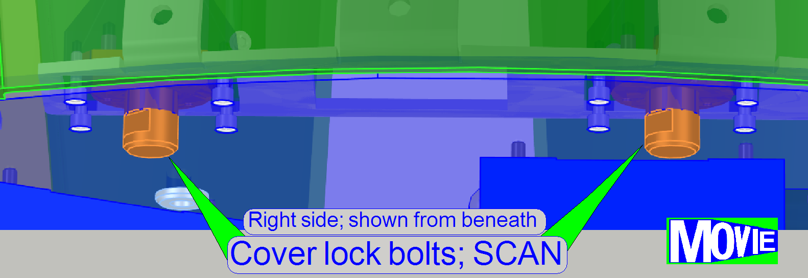 The cover fixing
of the upper housing is realized with 4 cover locks; two on the left and two on
the right side.
The cover fixing
of the upper housing is realized with 4 cover locks; two on the left and two on
the right side.
·
Drive the cover lock bolts (from beneath)
by a fourth revolution with the open end of the
combination wrench size 10 (delivered with the SCAN) to
open the cover fixing as usually, until it stops.
·
If all the four cover locks are open, the
upper housing can be removed in upward direction
Mount
the upper housing
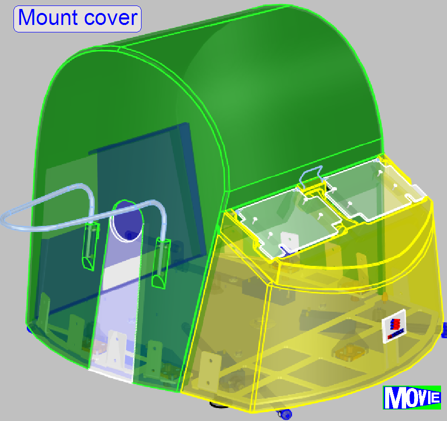
·
Mount the magazine unit cover first; before you are
mounting the upper housing.
·
Put the upper housing over the scanner and fit the
upper housing with the side wall on the left side.
·
If the lower part of the upper housing fits the base
plate correctly, close all the 4 cover locks (from
beneath) by the use of the open end of the combination wrench size 10 (delivered with the SCAN) to
close the cover fixing as usually, until it stops.
Remove
the magazine unit and slide loader cover
The magazine unit cover can be removed only if the
upper housing and the magazine stack covers are already removed and the handles in the
front are hidden.
·
The cover fixing of the magazine unit
cover is realized with 1 cover
lock in the front of the scanner; and two fixing
pins, one on the left and one on the right side; these fixing pins acting
independently.
·
Drive the cover lock bolt (from beneath)
by a fourth turn with the open end of the combination wrench size 10 (delivered with the SCAN) to
open the cover fixing as usually, until it stops.
·
If the cover lock is open, the magazine
unit cover can be removed in upward direction
To
mount the magazine unit and slide loader cover
·
Put the magazine unit cover
over the magazine unit, fit the fixing
pins on the left and right side.
·
If the magazine unit cover fits the base plate
correctly, the cover lock can be closed (from beneath) by driving the cover
lock bolt by a fourth turn with the open end of the combination wrench size 10 (delivered with the SCAN) to close
the cover lock as usually, until it stops.
·
Mount the magazine unit stack covers
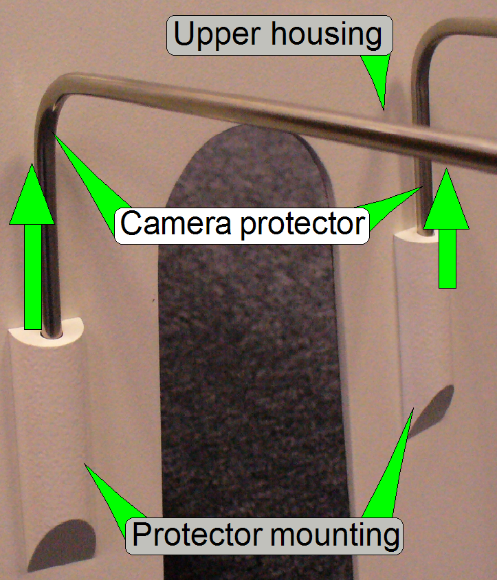 The camera
protector is designed to protect the scan camera against touching from the top
or from beside.
The camera
protector is designed to protect the scan camera against touching from the top
or from beside.
·
To remove (mount) the camera protector, pull both
parts evenly upward (push them evenly downward) out from the protector mounting
(into the protector mounting, until it stops).
·
Take care of the upper housing; do not scratch it when
the protector comes out of its mounting!
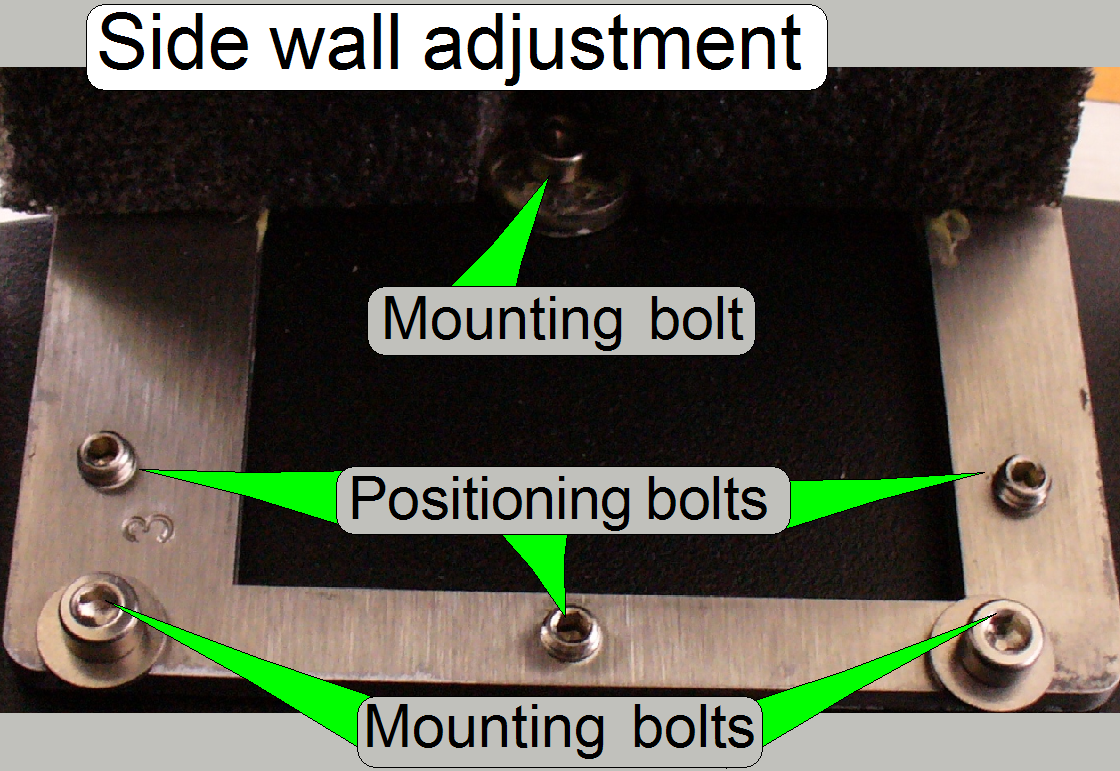
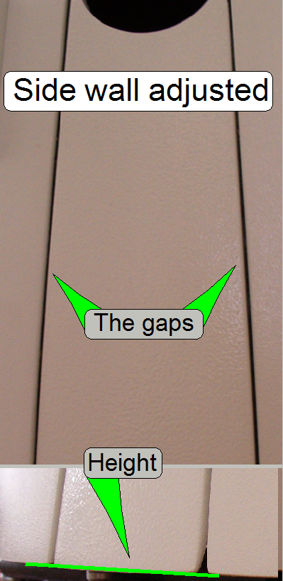 Adjust the
position of the side wall in relation to the upper housing of the scanner.
Adjust the
position of the side wall in relation to the upper housing of the scanner.
·
The height of the lower edge of the side wall and the
lower edge of the upper housing should be equal.
·
The gaps between the side wall and the upper housing
should be equal either on both sides of the side wall.
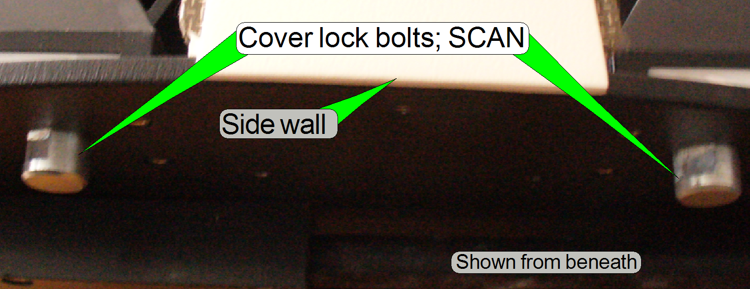 The cover fixing
is realized with 5 cover lock bolts; 4 for the upper housing and 1 for the
magazine unit cover.
The cover fixing
is realized with 5 cover lock bolts; 4 for the upper housing and 1 for the
magazine unit cover.
·
Drive the cover lock bolts by a fourth turn with the
open end of the
combination wrench size 10 (delivered with the SCAN) to open or close the
cover fixing as usually, until it stops.
·
If the cover locks are open, the upper housing can be
removed in upward direction
·
The magazine unit cover can be removed upward only if
the upper housing and the
magazine stack covers are already removed.
 The truss is
mounted onto the base plate by rubber feet to reduce vibration and noise during
scanning the sample. During shipping, this solution would allow that the
internal units can crash against the housing. Therefore, to avoid beating of
the housing by internal units, to inhibit the movement of the truss, and in
worst cases the demolishing of the housing,
the shipping bolt has to be tightened during shipping.
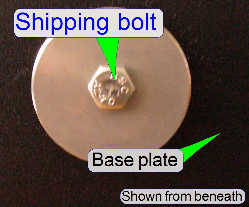
The truss is
mounted onto the base plate by rubber feet to reduce vibration and noise during
scanning the sample. During shipping, this solution would allow that the
internal units can crash against the housing. Therefore, to avoid beating of
the housing by internal units, to inhibit the movement of the truss, and in
worst cases the demolishing of the housing,
the shipping bolt has to be tightened during shipping.
·
Tighten the shipping bolt e.g. with the ring part of
the delivered combination wrench (size 10) before shipping, and
·
Loosen the shipping bolt after unpacking; before the
first sample will be scanned.
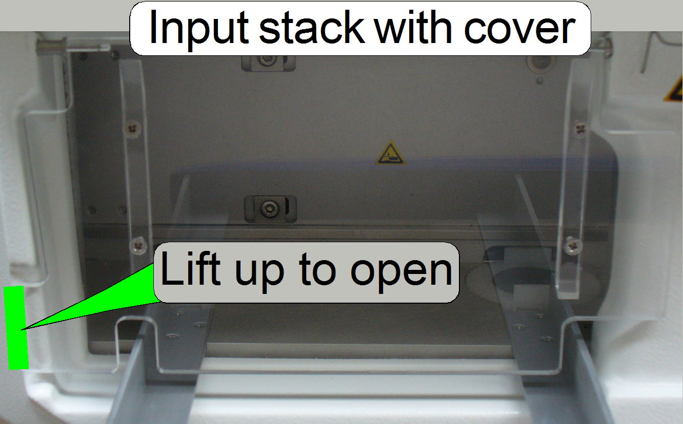 To fulfill
requirements of safety regulations in some countries, the magazine input stack as
well as the magazine output stack got an acryl glass cover. These covers are
opened manually by lifting up the lower outer part of the cover to insert the
magazines on the input stack side; on the same way the output stack cover is
opened to remove magazines. If 2 or more magazines are inserted into the input
stack, the cover stays open.
To fulfill
requirements of safety regulations in some countries, the magazine input stack as
well as the magazine output stack got an acryl glass cover. These covers are
opened manually by lifting up the lower outer part of the cover to insert the
magazines on the input stack side; on the same way the output stack cover is
opened to remove magazines. If 2 or more magazines are inserted into the input
stack, the cover stays open.
If the magazines are loaded from the input stack into the magazine
channel and only 1 magazine remaining in the input stack, the weight of the
cover itself moves the cover downward and closes so the input channel during
the magazine load procedure is done.
If the 2nd magazine is moved from the magazine channel into
the output stack, the cover will be opened by the magazine and stays open until
the magazines are removed.
Realization
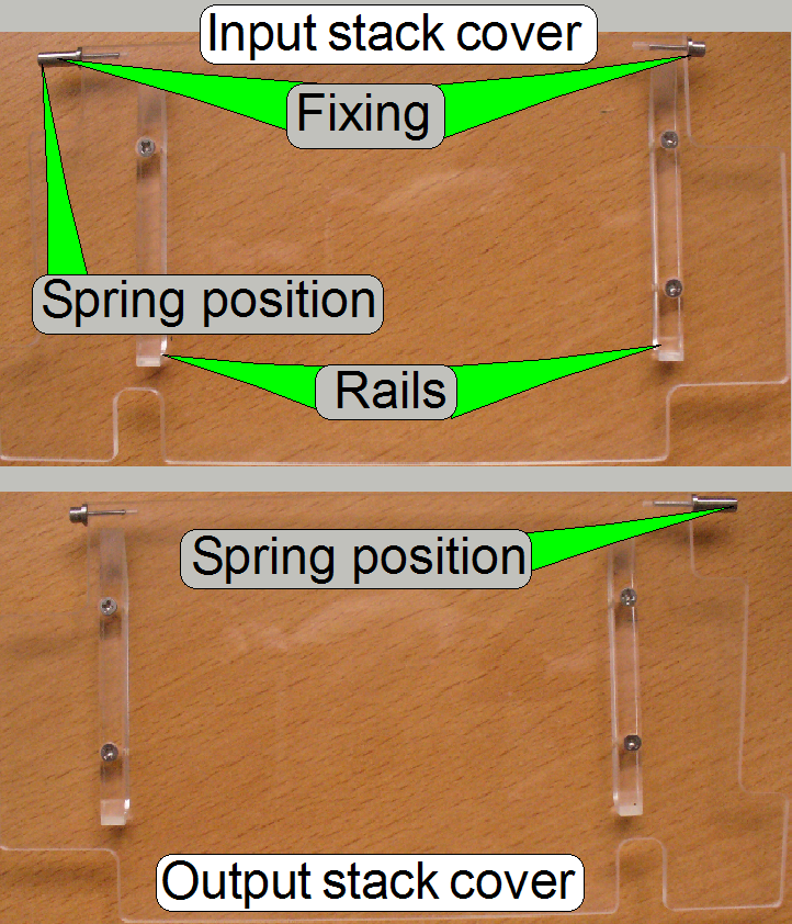 The shape of both
covers is identical, but the rails are mounted onto the opposite side.
The shape of both
covers is identical, but the rails are mounted onto the opposite side.
This way, the different shape of the fixing pins is also situated on the
opposite side. The shorter pin fixes the cover to the slide loader cover; the
longer pin is used to tauten the spring during cover removal or insertion on
the magazine unit side.
The upper corner of the magazines sidewall is in contact with the rails
of the acryl glass cover. The cover is closed by its own weight and gravity.
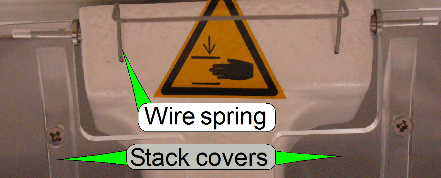
Spring
 The spring is
always inserted into the part of the magazine unit cover, never into the hole
of the slide loader cover.
The spring is
always inserted into the part of the magazine unit cover, never into the hole
of the slide loader cover.
The wire spring on the top of
the slide loader cover guaranties, that the gravity can always close the cover;
the cover must not be hold by this wire spring.
Remove
the input stack cover
1.
Open the cover in an angle of nearly 45º.
2.
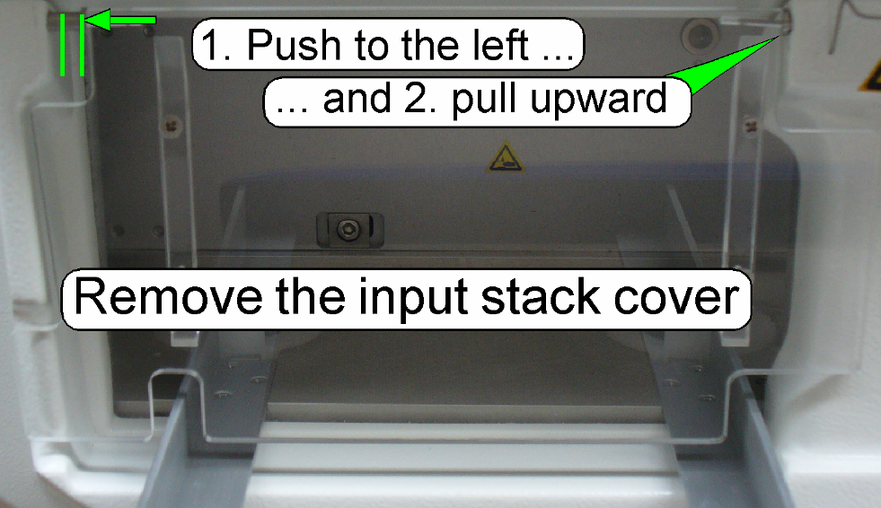 Push the input
stack cover to the left until it stops to strain the spring.
Push the input
stack cover to the left until it stops to strain the spring.
3.
Pull the right fixing carefully upward meanwhile the
cover is pressed to the left.
4.
Release the pressure on the left side slowly.
Take care on the spring; it may be lost easily.
Remove
the output stack cover
Do the steps described for the input stack cover logically. Because the
spring is inserted in the opposite position, push the output stack cover to the
right and pull the cover on the left side carefully.
Mount
the input stack cover
1.
Make sure, that the spring is inserted well and in the
correct position.
2.
Strain the spring with the longer pin of the acryl
glass cover fixing on the left side and move the right fixing (short pin)
downward; meanwhile the spring is strained click the shorter fixing pin into
its place.
Adjust
the position
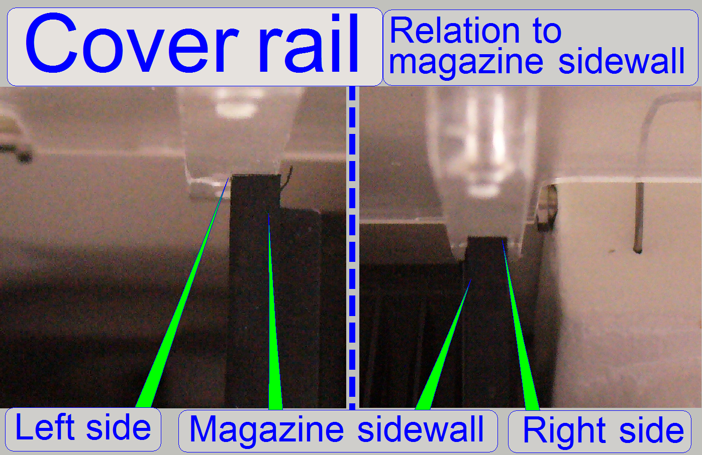 For a well
functioning of the magazine load procedure, even if magazines with only one or a
few slides are loaded, the position of the acryl glass cover rail in relation
to the magazine sidewall is very important.
For a well
functioning of the magazine load procedure, even if magazines with only one or a
few slides are loaded, the position of the acryl glass cover rail in relation
to the magazine sidewall is very important.
Because the parts of the housing can not be adjusted (except the
sidewall of the upper housing) the truss position (and so the position of the
magazine sidewall) have to be adjusted.
By loosening the
truss nuts and positioning of the
entire truss, the position of the magazine unit and so, the position of the
magazine in relation to the rails of the acryl glass cover can be adjusted.
2.
Loosen the truss mounting nuts (see below, “The truss”, “truss mounting” and “Adjust the truss
position”).
3.
Insert 3 magazines into the magazine input stack and 3
magazines into the magazine output stack.
4.
Adjust the truss
position so, that the rails of the acryl glass covers are fully over the
sidewalls of the magazine on the input and the output stack side; check all 4
positions.
5.
Tighten the truss mounting nuts.
6.
Insert 6 empty magazines into the magazine input
stack.
7.
Start the magazine load test and check the behavior of
the magazine during the magazine load procedure of each magazine on the input
stack side. The magazine should move evenly and smoothly downward, without
stocking, even if the cover will close. The output of the magazine is not
critical; but stocking of the magazine should also not occur.
8.
If the test is finished correctly, mount the upper cover;
otherwise repeat from step 2.
 In opposite to shipping,
the term “move” implies the move of the scanner manually by persons; without any means of conveyance.
In opposite to shipping,
the term “move” implies the move of the scanner manually by persons; without any means of conveyance.
For this action remove all cables, the camera and the camera protector
(if needed).
In the corners of the bottom plate the transport handles are realized.
Pull this handles toward yourself and rotate them upward. By using the handles,
the scanner can be so transported safely by two persons. After the destination
is reached, the handles can be hided again.
1.
Pull the handle toward yourself until it stops, then
2.
Rotate the handle upward.
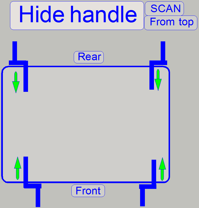
Hide the handles
· Rotate the handles
on the rear horizontally and outward, then shift them frontward until the
handles are hidden; see on the right.
· Rotate the handles
in the front horizontally and inward, then shift them in direction of the rear
until the handles are hidden; see on the right.
In opposite to the move, the using of the term “shipping” implies the
move of the scanner with any means of
conveyance; on the road or in any other form. Because in this case
vibration occurs, precautions have to be done to avoid damage of units or parts
of the cover, especially the painting.
To protect edges and parts of the housing use e.g. impact sound
insulation foil or equivalent plastic foam foil with a thickness of 2 ...
Requirements
·
Size 10 wrench (delivered with the scanner),
·
Utility knife, scissor,
·
Impact sound insulation foil or equivalent plastic
foam foil with a thickness of 2 ...
·
Usually used packaging materials like plastic bags,
bubble bags and bubble foils,
·
Further packaging materials like cardboard boxes,
sponge carpeted cardboard boxes,
·
Tesa film strip or equivalent adhesive strip to affix
foils and protectors,
·
Adhesive tape of about
Packaging
The main aspect during packaging is, to avoid scratches on units or
paintings during shipping and damaging of any shipped parts. High sensitive
parts need particular attention!
·
Pack each part always separately also by the use of
foil bags or bubble bags.
·
Put only parts together into the same box with nearly
the same weight and the same mechanical stability; heavy units or parts with
low mechanical stability should be packed into a separate box also and away
from each other.
·
Fill unused gaps and spaces in the boxes so, that the
parts can not move; and rubbing on each other may not occur.
Prepare the SCAN
shipping
1.
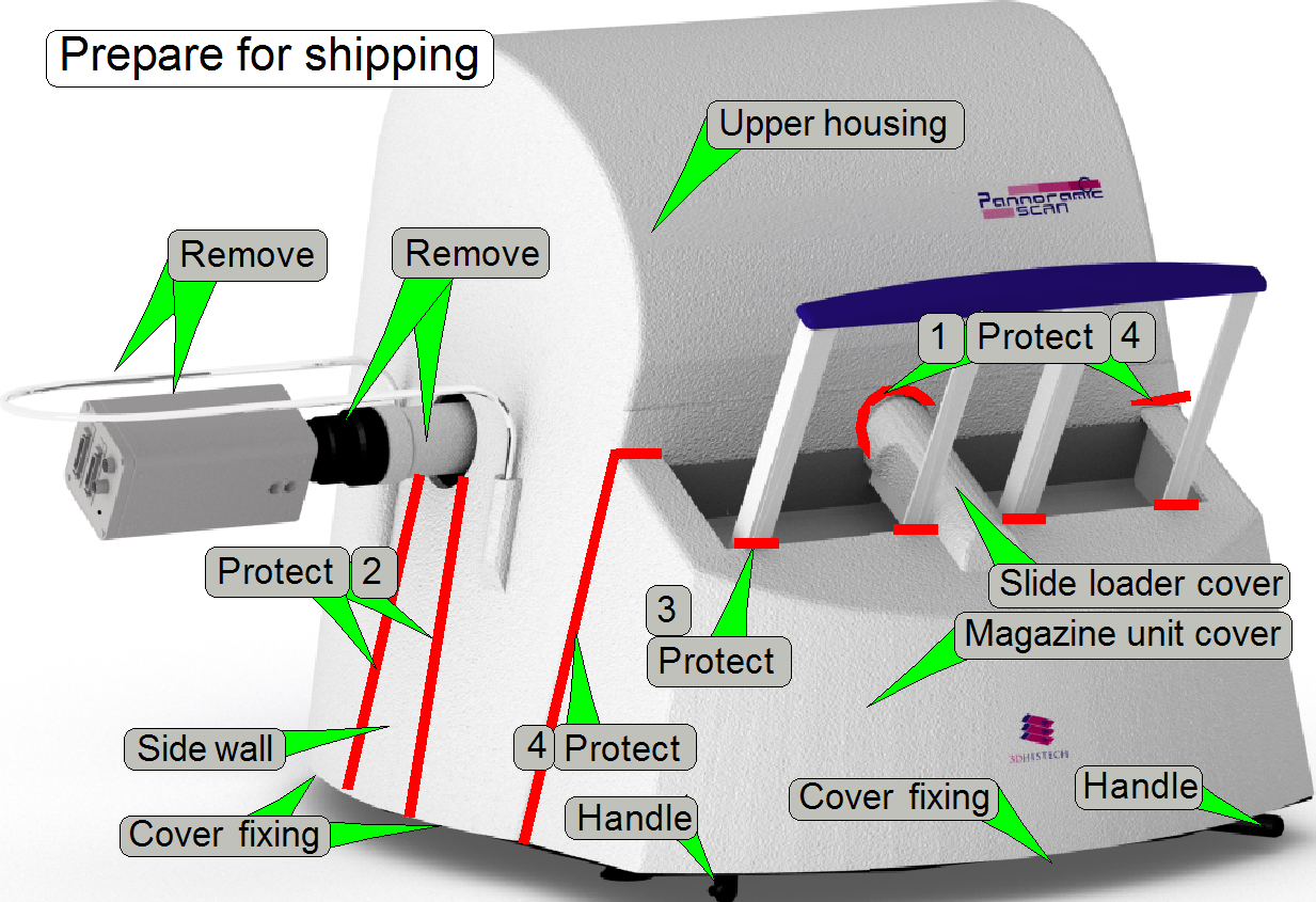 Set the X-Y-stage
to the position X=26 000 and Y=70 000 steps.
Set the X-Y-stage
to the position X=26 000 and Y=70 000 steps.
2.
Remove the camera, the camera adapter, the camera tube
and the camera protector.
3.
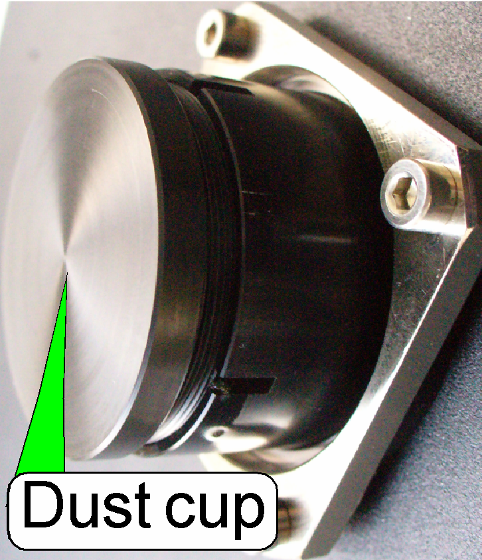 Screw in the dust cup for the tube mounting.
4.
Pack all these removed parts separately, see also “To
pack the accessories”.
5.
Remove the back wall and pack it.
6.
Mount the fluorescent lamp connector dust cup.
7.
Open all the cover fixings and remove the upper
housing, then the magazine unit cover.
8.
Remove the slide loader and pack it separately.
9.
Remove all the filters from the turret filter wheel.
10.
Protect the inner edge of the slide loader cover (1)
and the side wall (2).
11.
Protect the magazine stack rails (3) and mount the
magazine unit’s cover.
12.
With foil strips of a width about
13.
Lock the cover by rotating the cover lock bolts; and
check the proper fitting position of the protectors again.
14.
Tighten the
shipping bolt.
15.
Put the entire scanner into a plastic protecting bag.
16.
Put the scanner into the lower shipping shell of the
shipping box; fit the upper shell and close the shipping box. The upper shell
should be under pressure if the box is closed, to ensure so the proper fixing
of the scanner!
Slide
loader
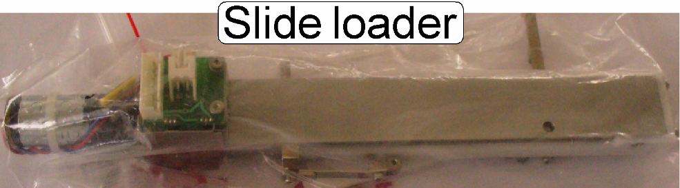 Put the slide loader
into a plastic (bubble) bag and then into a sponge carpeted box.
Put the slide loader
into a plastic (bubble) bag and then into a sponge carpeted box.
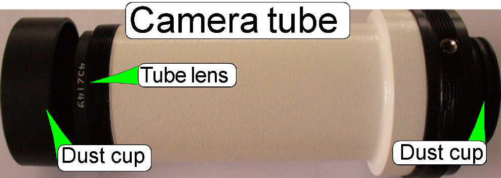 Camera tube
Protect the tube lens and the camera adapter opening by using the
appropriate dust cups and put it into a plastic protecting (bubble) bag.
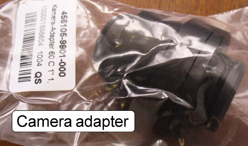 Camera adapter
Put it into a plastic protecting bag.
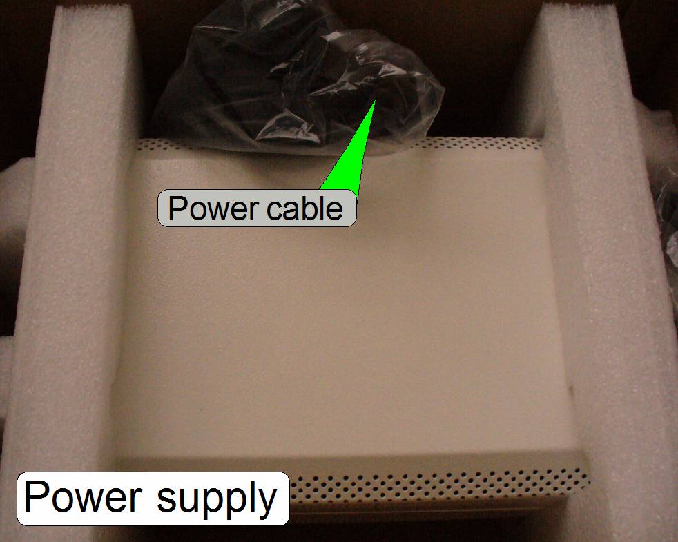
Use the original delivery box of the power supply; do not forget the
power cable.
Back
wall
Protect the back wall against scratching by using impact sound
insulation foil.
Camera
protector
Put it into a plastic bag.
Camera
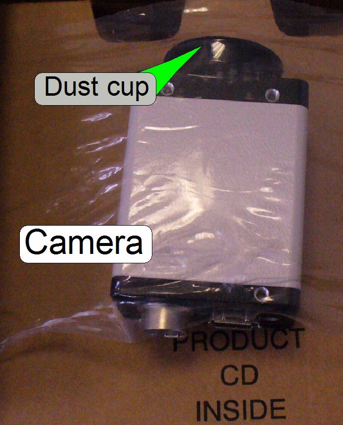 Protect the CCD of
the camera with the dust cup and fix the camera in its original delivery box.
Protect the CCD of
the camera with the dust cup and fix the camera in its original delivery box.
Cables
The FireWire and the USB cables should be packed each into a plastic
bag.
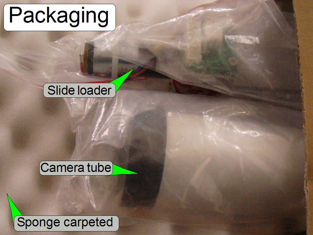 The slide loader
and the camera tube should be packed with particular attention.
The slide loader
and the camera tube should be packed with particular attention.

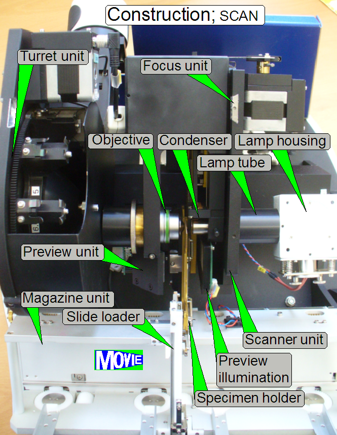
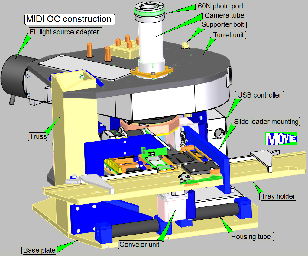
The SCAN consists of the following main units:
· Magazine unit with slide loader
· FL Reflector turret unit with camera tube mounting (not
shown here)
· X-Y-stage unit with specimen holder
· Focus unit with objective and condenser
· Preview unit with preview camera, preview objective and illumination
· Brightfield illumination
with lamp housing and illumination (lamp) tube
Watch video: “SCAN OC mountings;
construction”
· For
safety regulations regarding human health and scanner functionality please
refer to: Precautions
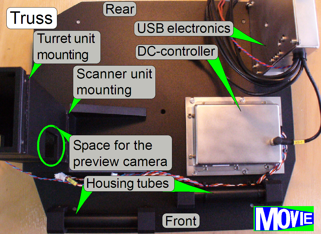
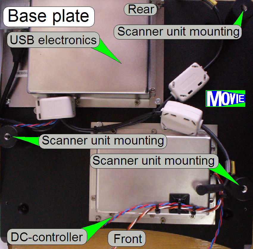
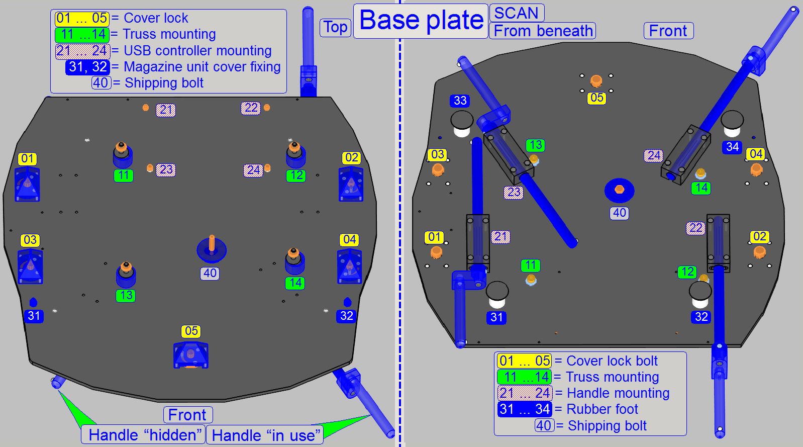 As a part of the
housing, the base plate contains the mountings for the following main parts:
As a part of the
housing, the base plate contains the mountings for the following main parts:
·
Truss
·
USB
controller box
·
Handles
to move the SCAN (mounted from beneath)
·
Base plate feet (mounted from beneath; not shown) and
·
Cover
locks for the upper housing and the magazine unit cover.
·
Rubber
feet of the truss are
mounted with
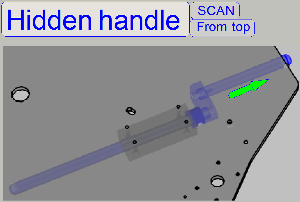
The handles are used to move the SCAN.
Each handle has two defined positions, the hidden position and the
position "in use" (as shown); in both positions a fixing is realized.
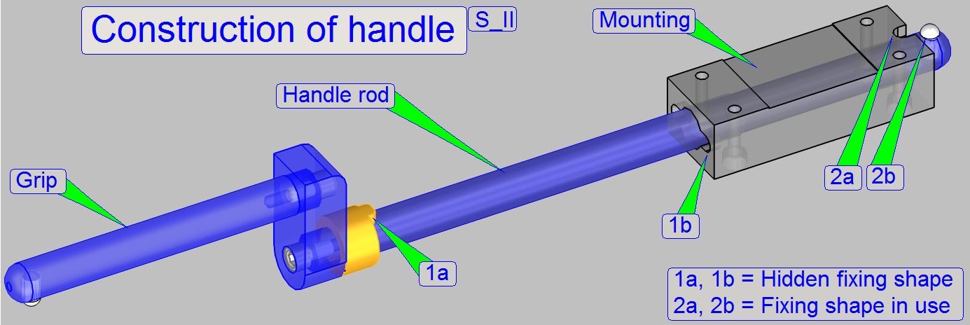
The fixing, shown as shapes 2a and 2b are used during moving the scan,
so the handle will not rotate, it stays always upward.
If the handle is pushed into its hidden position, the shapes 1a and 1b
fitting each other and the handle can not rotate downward by gravity.
- Before
rotating the handle sideward during hiding the handle, push the handle a
bit to release the fixing (2).
- If the hidden
position is reached, the fitting of the shapes (1) can be reached by pushing
and jarring the handle grip a bit upward and downward.
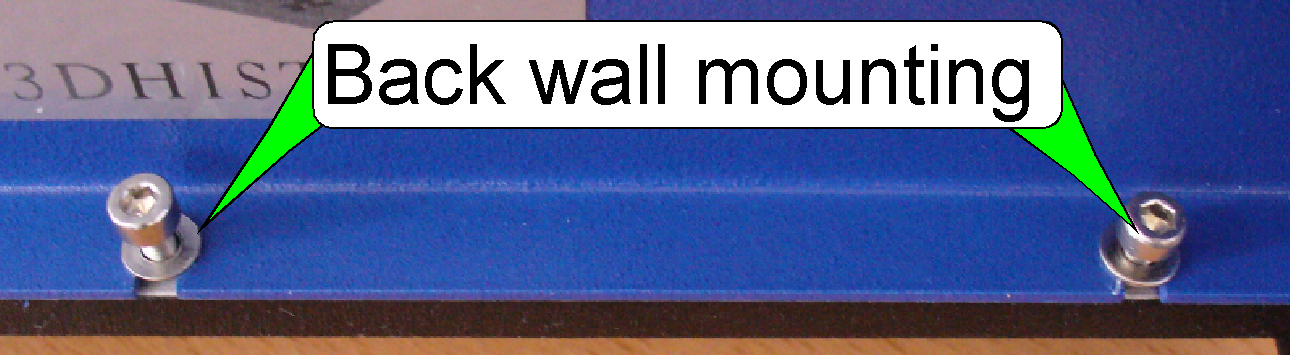 The
back wall is mounted with three
bolts and washers to the rear of the base plate (only 2 are shown).
The
back wall is mounted with three
bolts and washers to the rear of the base plate (only 2 are shown).
- Remove the
upper housing.
- If the three
bolts of the back wall mounting are removed, the back wall can be removed
backward.
- Mount the back
wall first, before the upper housing will be mounted.
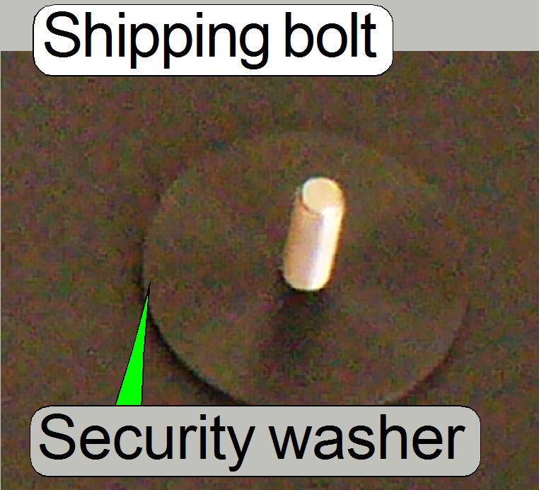 The
shipping bolt is secured by a washer, so it can not be lost if the
shipping bolt is fully unscrewed from the truss.
The
shipping bolt is secured by a washer, so it can not be lost if the
shipping bolt is fully unscrewed from the truss.
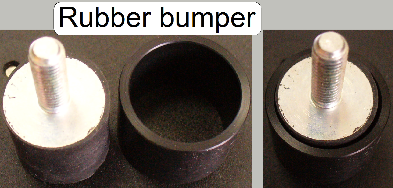 Each mounting for
the truss contains a rubber bumper to reduce noise and vibration during
scanning. The rubber bumpers are mounted to the base plate from beneath.
Each mounting for
the truss contains a rubber bumper to reduce noise and vibration during
scanning. The rubber bumpers are mounted to the base plate from beneath.
If the shipping bolt
is tightened, a tube, placed over the rubber part of the mounting, guarantees
the stable fixing of the truss to the base plate.
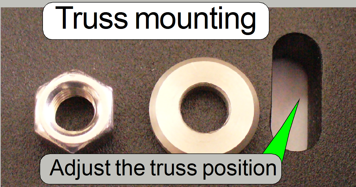 The truss is
mounted to the bolts of the rubber bumpers by using a washer and a bolt nut.
With a long hole solution, the position of the truss (the entire scanner) can
be adjusted in relation to the housing; no parts of the scanner must touching
the housing if all covers are mounted; see also “The stack covers”.
The truss is
mounted to the bolts of the rubber bumpers by using a washer and a bolt nut.
With a long hole solution, the position of the truss (the entire scanner) can
be adjusted in relation to the housing; no parts of the scanner must touching
the housing if all covers are mounted; see also “The stack covers”.
To ensure, that the entire scanner does not touch the housing, its
position can be adjusted; see also above “The stack covers”.
The rubber bumpers are mounted from beneath with
The long holes in the base plate allow a positioning of the truss in the
mathematical X-direction and the long holes in the truss allow the positioning
in Y-direction.
·
Adjust the position of the truss so, that no internal
part touches the housing and the stack
covers are working correctly.
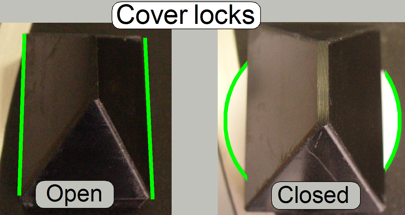 The cover locks
are fixing the cover to the base plate. By rotating their mechanics by a fourth
turn with the bolt from beneath, the locks are opened or closed as shown (use
the open end part of the
delivered combination wrench size 10).
The cover locks
are fixing the cover to the base plate. By rotating their mechanics by a fourth
turn with the bolt from beneath, the locks are opened or closed as shown (use
the open end part of the
delivered combination wrench size 10).
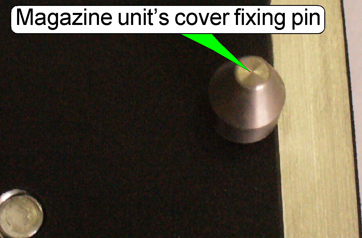
The parallel pin without head fixes the magazine units cover in its
position on both sides, in relation to the magazine unit cover lock and the
base plate.
USB
electronics box mounting
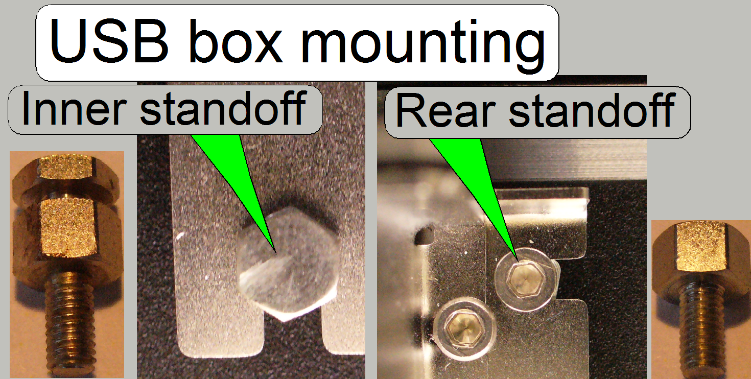 To allow an easy
exchange of the USB controller box,
the inner, inaccessible standoffs have a slot, in which the unit is shifted in;
during the rear standoffs are fixing the USB box by using a bolt.
To allow an easy
exchange of the USB controller box,
the inner, inaccessible standoffs have a slot, in which the unit is shifted in;
during the rear standoffs are fixing the USB box by using a bolt.
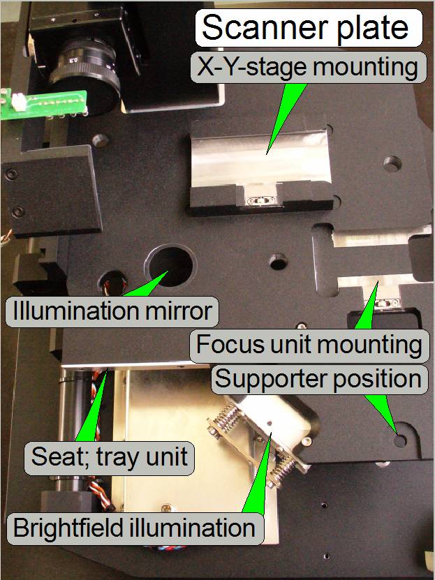
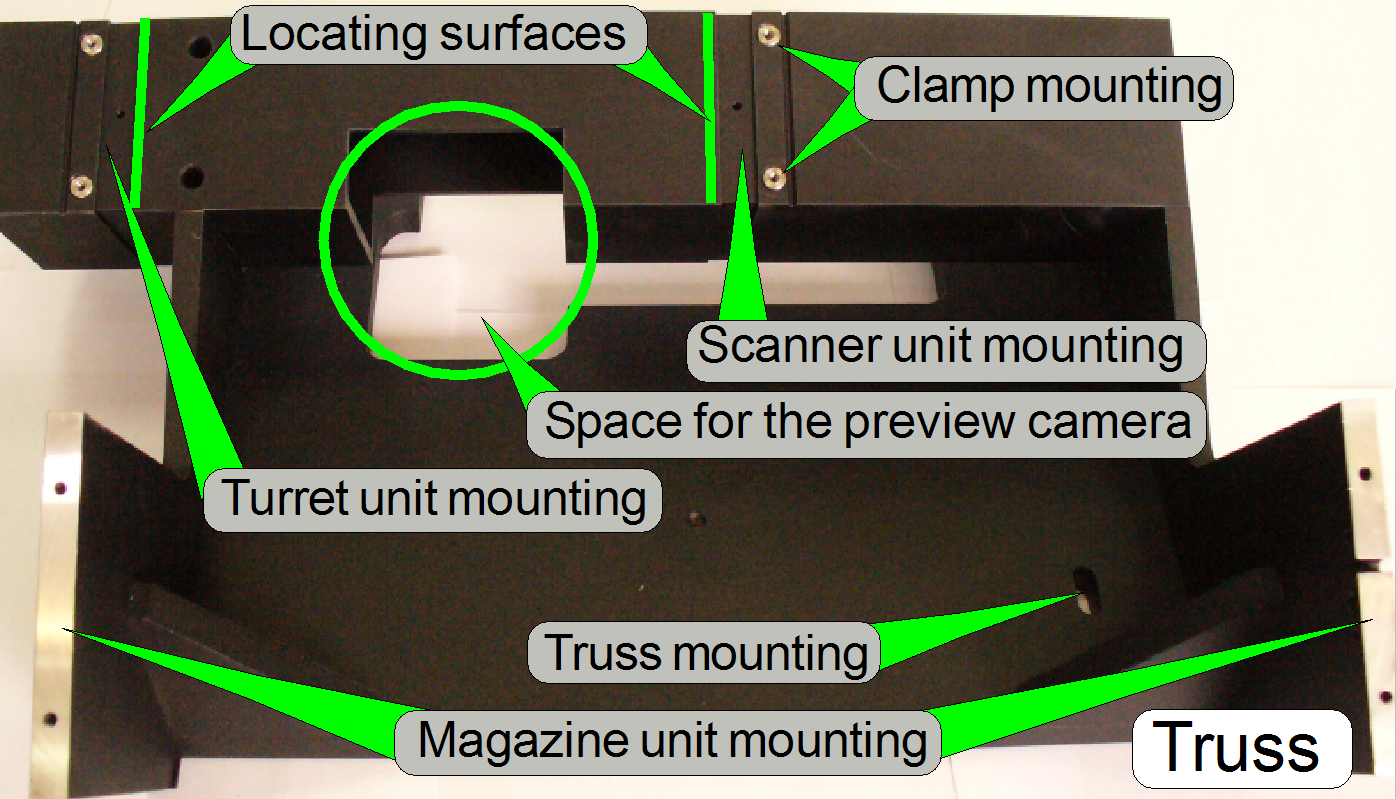 Each separate unit
of the scanner is mounted on the truss. The truss defines, with the position of
the mountings, the distances of the units to each other. The mounted main units
are:
Each separate unit
of the scanner is mounted on the truss. The truss defines, with the position of
the mountings, the distances of the units to each other. The mounted main units
are:
·
Turret unit
and
Turret and scanner unit
mounting
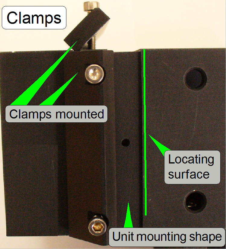
 Because the
distance between turret unit and scanner unit is important, the mounting is
realized by using a locating surface and this is fixed by clamps.
Because the
distance between turret unit and scanner unit is important, the mounting is
realized by using a locating surface and this is fixed by clamps.
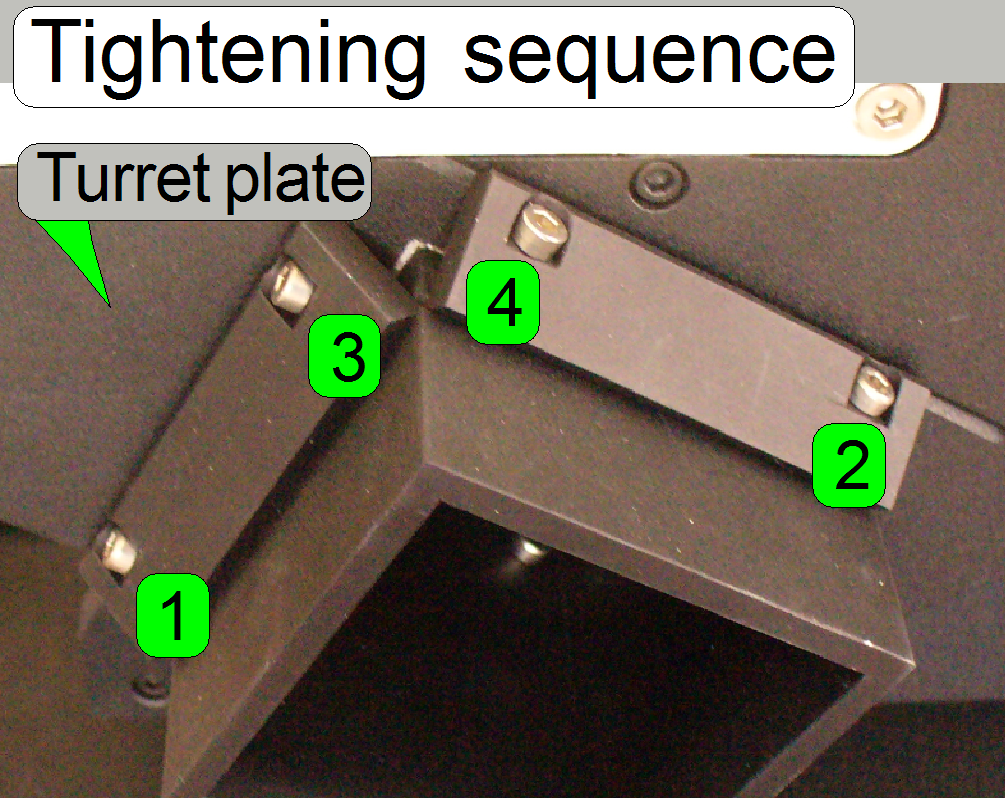
Only by tightening the clamps in the right sequence, the locating
surface fits correct.
The scanner plate is tightened logically in the same sequence.
To remove the turret plate or scanner plate, loosen the bolts 1 and 3
and remove the clamp, fixed with the bolts 2 and 4; then the plate can be
pulled toward you.
See also: Exchange
the scanner unit Remove the turret
unit from Pannoramic SCAN
Drillings of the magazine
unit position adjustment
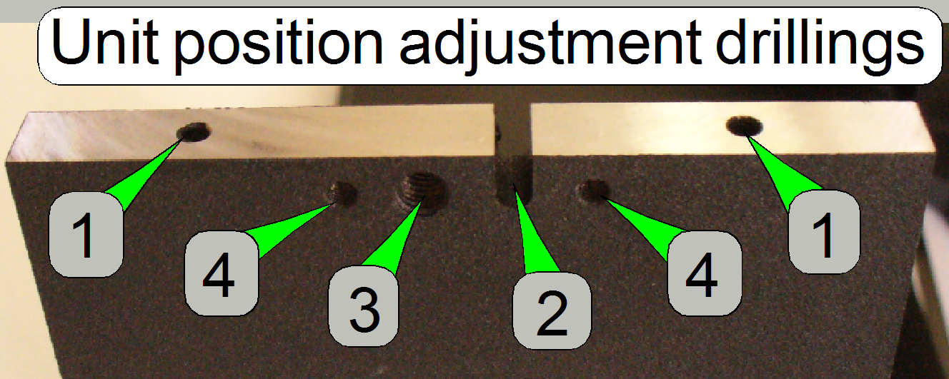 1= Magazine unit
mounting
1= Magazine unit
mounting
2= Magazine unit position
fixing
3=Magazine unit position
adjustment
4= Position adjustment cover
 With the locating
surface, the correct distance between scanner plate and turret plate is
defined; the scanner plate is mounted by the use of clamps and
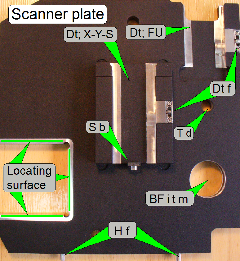
contains the mountings and fixings for the following main units:
With the locating
surface, the correct distance between scanner plate and turret plate is
defined; the scanner plate is mounted by the use of clamps and
contains the mountings and fixings for the following main units:
·
Preview
and barcode unit (the horseshoe) and
·
Brightfield
illumination tube with lamp
housing
Each unit is inserted until it stops, there must not be a gap between
bumper surface and unit mounting. Only this way the light path will be correct.
Dt; X-Y-S: Dovetail; X-Y-stage
unit
Dt; FU: Dovetail; Focus
unit
Dt f: Dovetail
fixing
S b: Stage bumper
BF i t m: Brightfield
illumination tube mounting
H f: Horseshoe
fixing
T d: Technological
drill
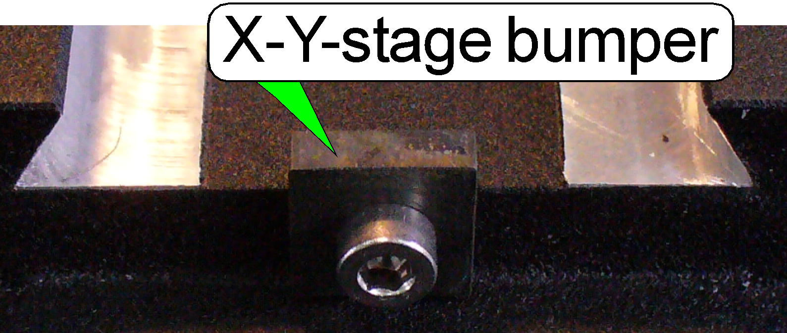
The X-Y-stage bumper defines the correct position of the X-Y-stage or
slide in relation to the focus unit or objective and the position of the
X-Y-stage in relation to the magazine unit.
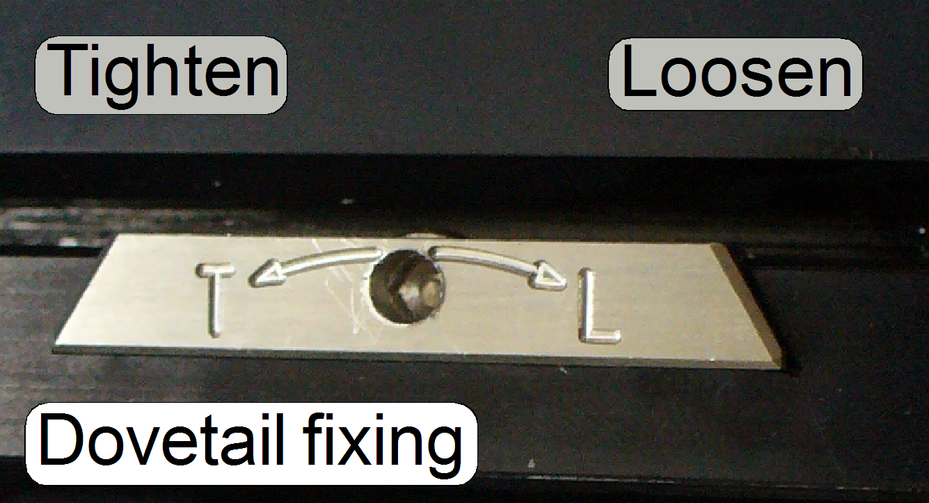
T=tighten
L=loosen
In opposite to the usual rotation direction, the dovetail fixing is
rotated clockwise to loosen the fixing, as shown.
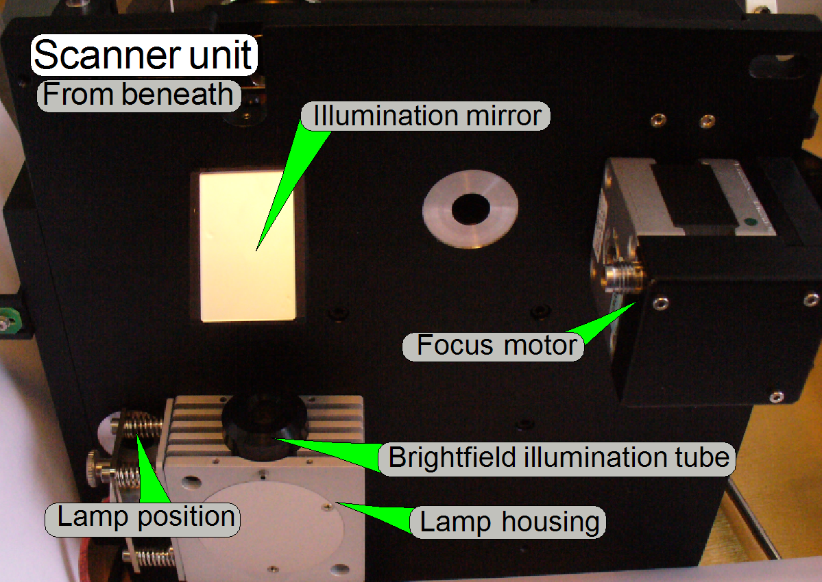
Brightfield
illumination tube mounting
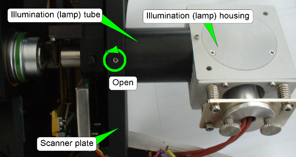
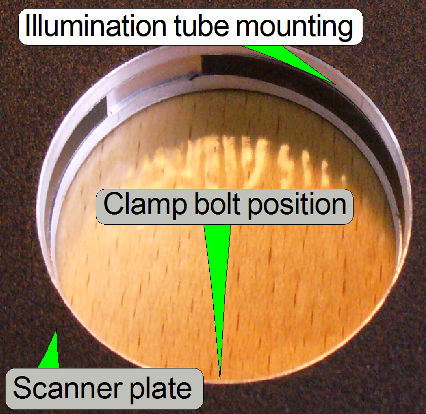
The drill of the brightfield
illumination tube contains a tightening ring; if the clamp bolt is
tightened, the ring is strained and fixes so the position of the tube.
Open the clamp bolt and pull the lamp tube with the lamp housing to the
right.
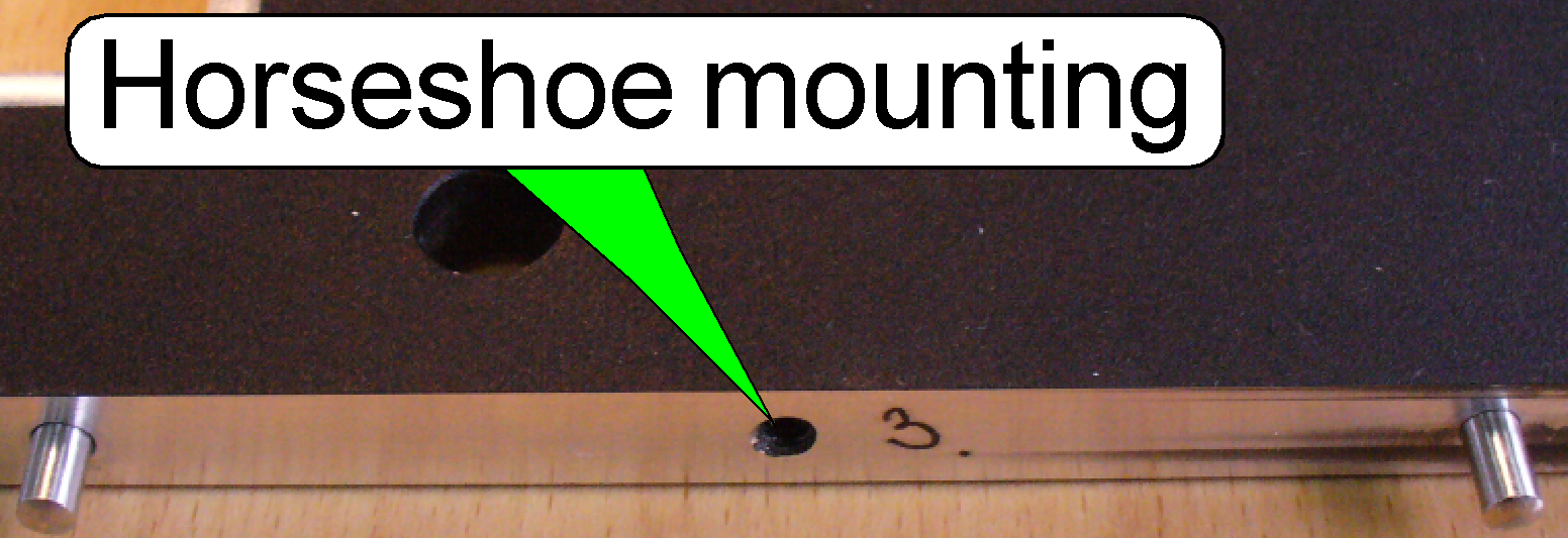
The horseshoe mounting contains two fixing pins to define the position
and a threaded hole for the mounting bolt.
Horseshoe with DFK 21F04
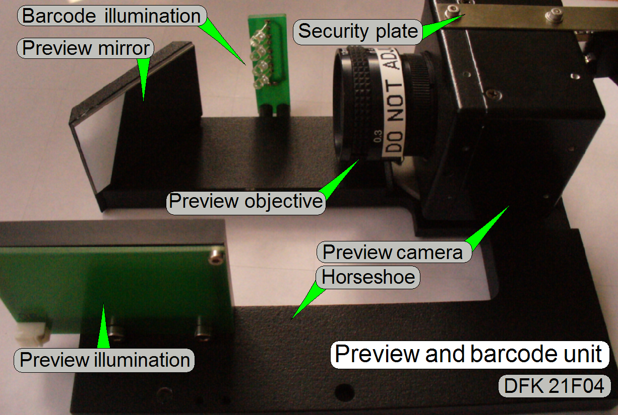
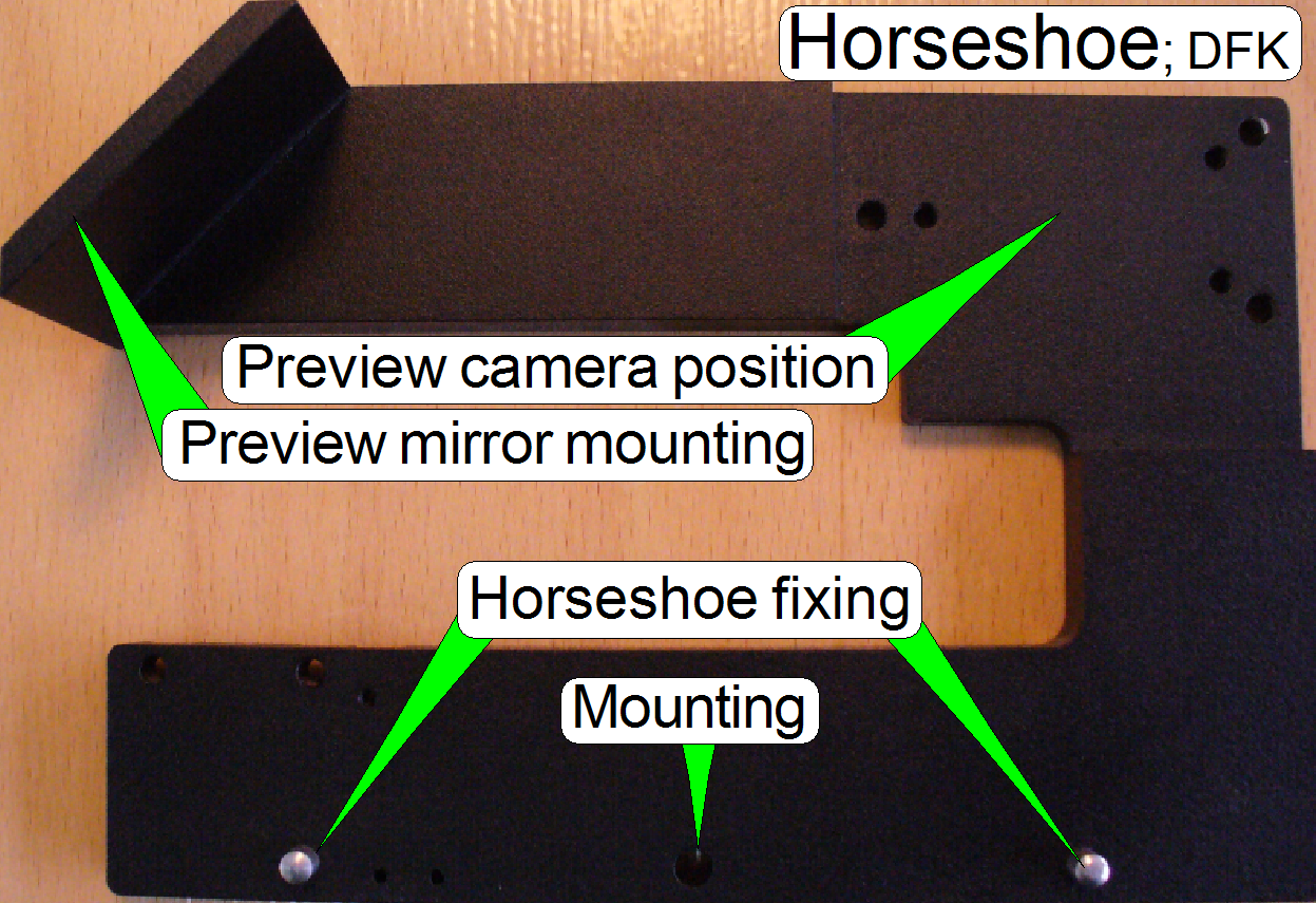 The horseshoe is
mounted to the scanner plate by using two fixing holes and one mounting bolt;
it contains the entire preview and barcode unit.
The horseshoe is
mounted to the scanner plate by using two fixing holes and one mounting bolt;
it contains the entire preview and barcode unit.
The main components are:
·
Preview camera with
auxiliary mounting plate
· Preview illumination (backlight) and
Horseshoe with VR magic
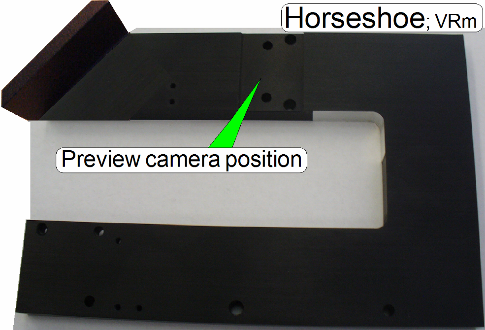
· The
construction of the camera mounting is similar as in the P250.
Turret plate
 With the locating
surface, the correct distance between turret plate and scanner plate is
defined; the turret plate is mounted by the use of clamps and
contains the mountings and fixings for the following main units:
With the locating
surface, the correct distance between turret plate and scanner plate is
defined; the turret plate is mounted by the use of clamps and
contains the mountings and fixings for the following main units:
·
EPI-fluorescent
illumination unit
Construction of the FL
filter turret unit
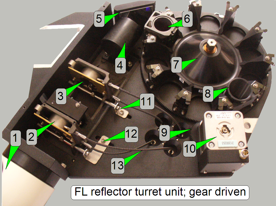 1 Fluorescent
light input connector
1 Fluorescent
light input connector
2 Aperture
stop diaphragm
3 Field
stop diaphragm
4 Condenser
5 Mirror
6 Filter
block
7 Filter
wheel
8 FL
image path cover tube
9 Gear
wheel
10 Turret
motor
11 Field
size adjustment
12 Aperture
size adjustment
13 Flexible
shaft for the position adjustment bolts
See also: FL
reflector turret unit

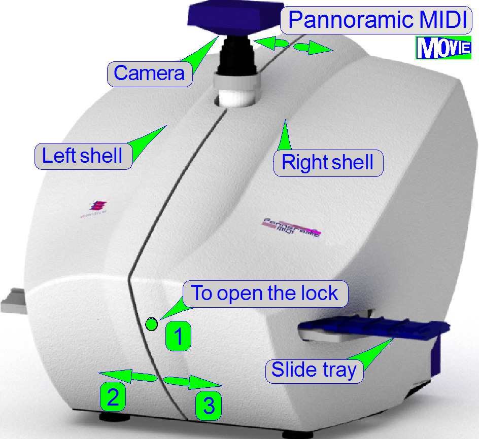
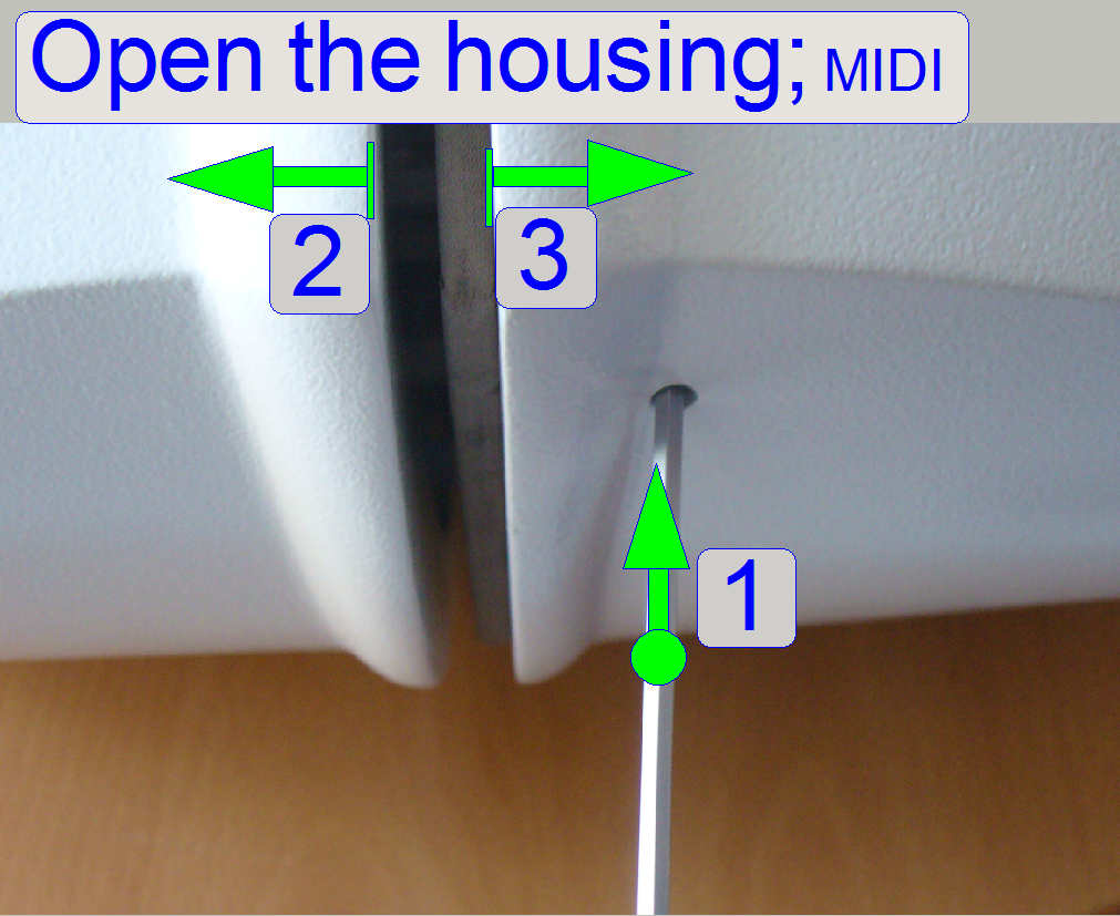
The housing of the

1.
 Press a
2.
The left shell and the right shell respectively can be
moved sideward by about
3.
If the shell is fully pulled sideward, the shell will
be removed; there is no further security.
If the shells are inserted into the upper and lower housing tubes from the
left side and from the right side respectively, press the shells to each other
until the lock snaps in.
Allowed slide dimensions are:
Length: 75.00
to
Width: 25.00
to
Thickness: 00.95
to
Since January
- If the first character of the serial number is an
“S” the tool is used to check the slide dimensions
of the scanners “SCAN, “
- If the first character of the serial number is a “P” the tool is used to check the
slide dimensions of the scanner “P250”.
·
Please check
the slide dimensions before filling the tray with slides!
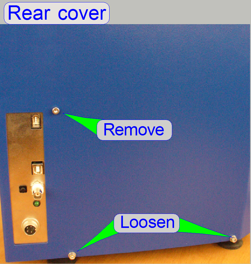
1.
Remove the cover shells as described above
2.
Remove all
the cables from the USB controller
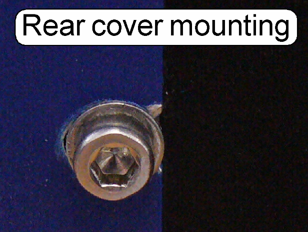
3.
Remove the mounting bolt of the USB controller
4.
Loosen (or remove) the 4 mounting bolts of the rear
cover to the base plate (only two are shown, the other two bolts are fixing the
rear cover from the left side and the right side respectively).
5.
The rear cover can be now removed upward.
 In this chapter,
only the main differences are described, in relation to the SCAN. For not shown
components and parts, please refer to the appropriate description of the SCAN.
In this chapter,
only the main differences are described, in relation to the SCAN. For not shown
components and parts, please refer to the appropriate description of the SCAN.
· For
safety regulations regarding human health and scanner functionality please
refer to: Precautions
·
In the
·
 In opposite to the
SCAN, the image
path is arranged in vertical direction, so the arrangement of the
components is modified.
In opposite to the
SCAN, the image
path is arranged in vertical direction, so the arrangement of the
components is modified.
The truss and base plate contains the mountings for:
· Housing tubes
· Rubber feet
(mounted from beneath)
The scanner unit mounting and the turret
unit mounting uses the same principle as shown for the SCAN.
· For more
information please refer to the description of the SCAN, “Truss” and “Scanner plate”.
See also: Remove
the turret unit from Pannoramic MIDI
Watch video: “MDI OC mountings;
construction”
 The brightfield illumination housing
is mounted directly onto the scanner plate from beneath. An illumination mirror
reflects the light from the illumination
tube directly to the
condenser of the focus unit.
The brightfield illumination housing
is mounted directly onto the scanner plate from beneath. An illumination mirror
reflects the light from the illumination
tube directly to the
condenser of the focus unit.
The mounted main units of the scanner plate are:
· Preview and barcode unit (the
horseshoe)
· Brightfield illumination housing
· Brightfield illumination
mirror
· Shoulder for the
tray- and slide loader unit mounting
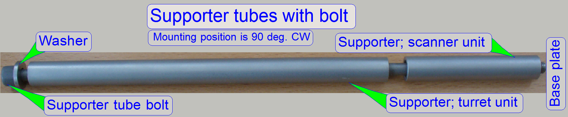 Because the
scanner and turret plate is placed horizontally, a supporter tube with bolt increases the mechanical stability and guarantees
the parallelism of both units to each other and to the base plate.
Because the
scanner and turret plate is placed horizontally, a supporter tube with bolt increases the mechanical stability and guarantees
the parallelism of both units to each other and to the base plate.

The DESK housing consists of an upper and a lower housing; the upper
housing is mounted to the lower housing by two bolts, one from the left side and
one from the right side. The lower part of the upper housing is held by clamps;
these acting independently if the upper housing is shifted frontward.
If the mounting bolts for the upper housing are removed on both sides,
the DESK can be opened.
1.
Remove the upper cover mounting bolts on both sides
2.
 Pull the rear part
of the upper housing upward of about
Pull the rear part
of the upper housing upward of about
3.
Shift the upper housing in direction to the front.
4.
Remove the camera protector as
required, see SCAN.
5.
Rotate the DESK to the right and put it onto its right
side. Take care on the painting, do not scratch it!
6.
Loosen (or remove) the 3 mounting bolts of the lower
housing from the base plate.
7.
Rotate the DESK return onto the feet and shift the
entire lower housing backward.
Allowed slide dimensions are:
Length: 75.00
to
Width: 25.00
to
Thickness: 00.95
to
Since January
- If the first character of the serial number is an
“S” the tool is used to check the slide dimensions
of the scanners “SCAN, “
- If the first character of the serial number is a “P” the tool is used to check the
slide dimensions of the scanner “P250”.
·
Please check
the slide dimensions before insertion of slides!
 Since the software
version 1.18 (March 2014), the DESK may be equipped with a 60N photo port and
is able to handle the CIS camera also.
Since the software
version 1.18 (March 2014), the DESK may be equipped with a 60N photo port and
is able to handle the CIS camera also.
See also: “Prerequisites” and “Scan cameras”
8.
 Shift the lower
housing from the back to the front so, that the mounting of the lower housing
is shifted between the base plate and the washers of the mounting bolts.
Shift the lower
housing from the back to the front so, that the mounting of the lower housing
is shifted between the base plate and the washers of the mounting bolts.
9.
Rotate the DESK to the right and put it onto its right
side. Take care on the painting, do not scratch it!
10.
Press the rear part of the lower housing against the
base plate so, that there is only a very small or no gap and tighten the fixing
bolt on the front left side.
11.
Rotate the DESK
to the left and put it onto its left side. Take care on the painting, do not
scratch it!
12.
Now press the right part of the lower housing to the
front and tighten the appropriate mounting bolt in the front.
13.
Finally, tighten the mounting bolt on the rear.
14.
Put the DESK return onto the feet and mount the upper
housing.
15.
Insert the lower fixings into the appropriate slots of
the lower housing and push the upper housing in direction of the rear.
16.
Fit the rear part of the upper housing with the upper
part of the lower housing and drive in the mounting bolts from the left and
right side.
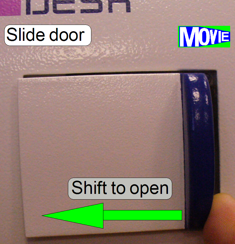 The mechanical construction
of the slide door allows the shift of the door handle to the left or to the
right respectively; this is a “one finger action”. Please shift the lower part
of the door handle to the left to open the door and shift the lower part of the
door handle to the right to close the door. The construction of the door
mechanics keeps the door closed automatically, therefore a resistance can be
felt if the door will be opened.
The mechanical construction
of the slide door allows the shift of the door handle to the left or to the
right respectively; this is a “one finger action”. Please shift the lower part
of the door handle to the left to open the door and shift the lower part of the
door handle to the right to close the door. The construction of the door
mechanics keeps the door closed automatically, therefore a resistance can be
felt if the door will be opened.
If the slide door is opened during the scan process is in progress, the
scan process will be stopped until the door is closed again; to avoid finger
squeezing.
Important
Please do not pull the door
handle to open or close the door!
Watch video: “Handle the slide door”
 Construction of the Pannoramic DESK
Adjust the scanner
plate position
Adjust the door sensor
position
Adjust the specimen
holder fixing
Adjust the supporter
of the specimen holder
Check the gap between
slide leader and specimen holder
The mechanical construction of the DESK includes a base plate and the
scanner plate only. In this chapter only the DESK specific components and
adjustments are described.
· Images
about the construction can be found in the DESK
gallery, or
· Watch the slide show “Pannoramic DESK”
· For
safety regulations regarding human health and scanner functionality please
refer to: Precautions
The base plate contains the USB- and the
DC-electronics box.
The scanner unit mounting is realized with three rubber feet and three distance
peaces.
·
The rubber feet are mounted to the base plate with 5mm
hexagon key bolts from beneath.
·
The scanner plate is mounted to the distance peaces
with 5mm hexagon key bolts from the top.
In the DESK, like in the
The mounted main units of the scanner plate are:
- Focus unit
- X-Y-stage unit
- Preview and barcode unit
(the horseshoe)
- Brightfield illumination
housing
- Brightfield
illumination mirror
- Image path of
the DESK is mounted onto the focus unit by using a mirror tube;
this is mounted by using a dovetail foot.
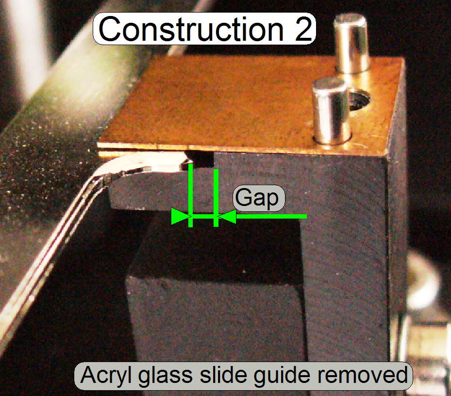
 Because the slide is
inserted or removed manually into the DESK, the specimen holder must be
fixed during these actions.
Because the slide is
inserted or removed manually into the DESK, the specimen holder must be
fixed during these actions.
If the specimen holder is in the Home1,2 position or anywhere in
direction to the negative limits, the slide action can be done. In this
position, the specimen holder is fixed on the right side and supported by the
specimen holder supporter on the left side. With this solution, the slide
insert or remove action can be done safely, without bending the specimen holder
or the parallelogram. Tighten the slide guide mounting bolt with care; acryl glass may burst
easily!
Furthermore, the specimen holder movement in Z-direction must not be
limited by the acryl glass slide leader guide if the focus position of 2400
steps is reached (during scanning or slide movements).
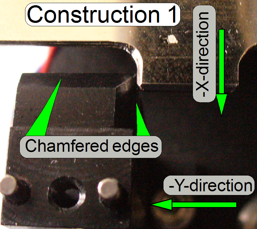 The right hand
supporter of the specimen holder fixing contains chamfered edges in –X- and
–Y-direction, so the specimen holder fixing guide will not jam if the specimen
holder is moved in negative direction.
The right hand
supporter of the specimen holder fixing contains chamfered edges in –X- and
–Y-direction, so the specimen holder fixing guide will not jam if the specimen
holder is moved in negative direction.
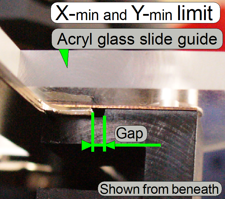
 If the limit in
–X-direction is reached, a small gap of about
If the limit in
–X-direction is reached, a small gap of about
Adjust the scanner plate
position
To ensure, that the scanner plate and any internal part do not touch the
housing, its position can be adjusted.
The rubber feet are mounted to the base plate from beneath and the scanner
plate from the top to the distance peaces with 6mm hex key bolts.
The long holes in the base plate allow a positioning of the scanner
plate in the mathematical X-direction and the long holes in the scanner plate
allow the positioning in Y-direction (not shown).
·
Loosen the specimen holder mounting (4) on the right
side (see “Specimen holder fixing
·
Mount the lower housing (see above “To mount the lower
housing”).
·
Adjust the position of the scanner plate so; that no
internal part touches parts of the correctly mounted lower housing.
·
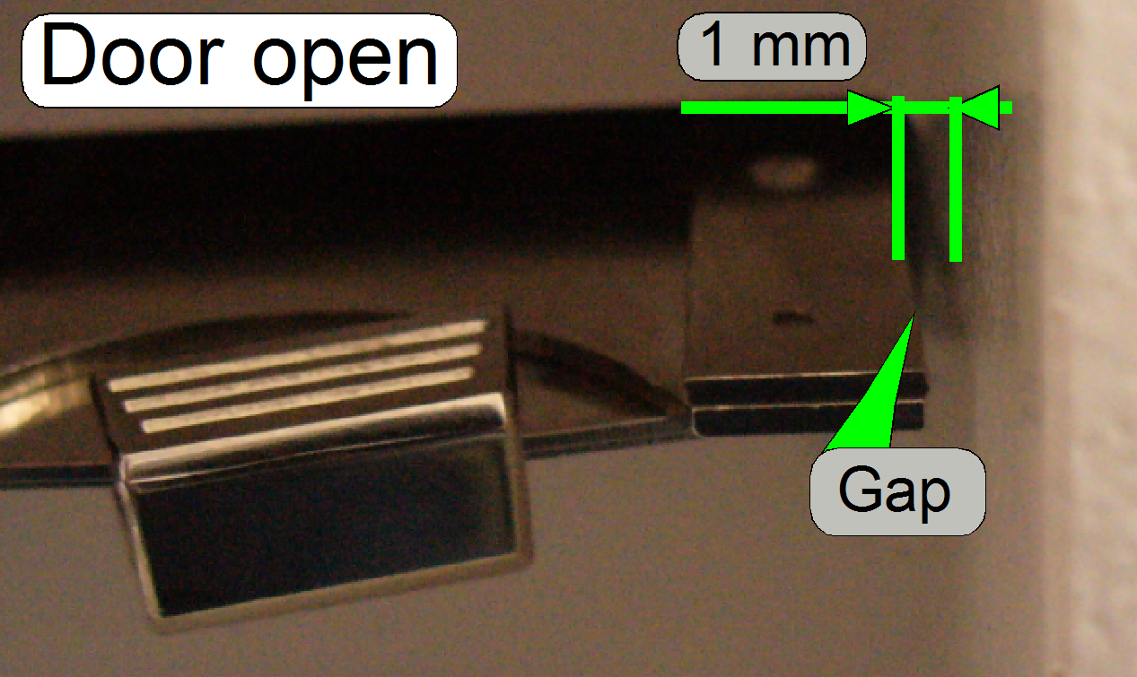
Especially, check the distance of the focus plate and 8:1
divider of the focus unit in relation to
the back wall, no part of the focus unit should touch the back wall; a gap of
about 0.5 ...1 mm is required (adjust the
Y-position)!
·
Fit the upper housing, open the slide door and check
the gap between specimen holder and right side of the housing, if the specimen
holder is in the negative limits; there should be a gap of about
·
Furthermore, check the position of the mirror tube; it
should be nearly in the middle of the housing opening.
·
If the scanner plate position was modified or adjusted
the following adjustments have to be done or checked:
o
The door sensor acting position (see “The door closed position”
and “To adjust
the door sensor position”
o
The specimen holder fixing position (see “Adjust the
specimen holder fixing”)
o
Adjust the supporter position (see “Adjust the supporter
position on the left side of the specimen holder”)
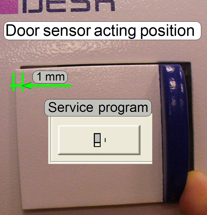 The door sensor
should signal the “door closed” state safely, if the door is closed; therefore
the door sensor should acting about 1 ...
The door sensor
should signal the “door closed” state safely, if the door is closed; therefore
the door sensor should acting about 1 ...
The allowed
slide dimensions are:
Length: 75.00
to
Width: 25.00
to
Thickness: 00.95
to
Since January
- If the first character of the serial number is an
“S” the tool is used to check the slide dimensions
of the scanners “SCAN, “
- If the first character of the serial number is a “P” the tool is used to check the
slide dimensions of the scanner “P250”.
·
Please check
the slide dimensions before insertion of slides!
Adjust the door sensor position
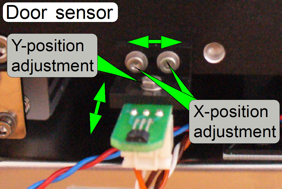 This adjustment
should be done only, if there are problems with recognizing of the “door
closed” state, e.g. if the scan process is interrupted without any
interpretable reason; if the mountings or adjustment bolts was loosened or the
position of the scanner plate was adjusted or modified.
This adjustment
should be done only, if there are problems with recognizing of the “door
closed” state, e.g. if the scan process is interrupted without any
interpretable reason; if the mountings or adjustment bolts was loosened or the
position of the scanner plate was adjusted or modified.
This adjustment assumes that the scanner plate position is correct, see
above “Adjust the scanner plate position”.
1.
Remove the upper cover (see above).
2.
Loosen the mounting or adjustment bolts.
3.
Move the sensor to the left or to the right as desired
and tighten the adjustment or fixing bolts.
4.
by loosening the Y-adjustment nut, the sensor can be
adjusted in Y-direction.
5.
Fit the upper cover as required for the normal work.
6.
Check the “door closed” position
as described above.
7.
Repeat from step 1 until the door closes correctly.
8.
Check this adjustment again if the upper cover is
fixed with the bolts.
· 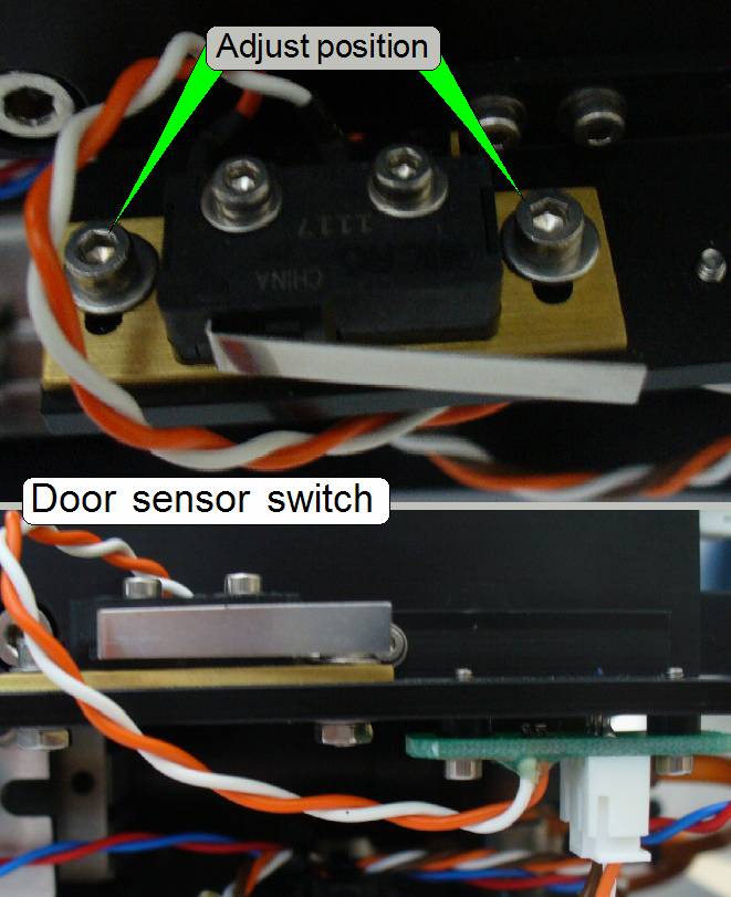 Since 2014 the
hall sensor is replaced by a micro switch.
Since 2014 the
hall sensor is replaced by a micro switch.
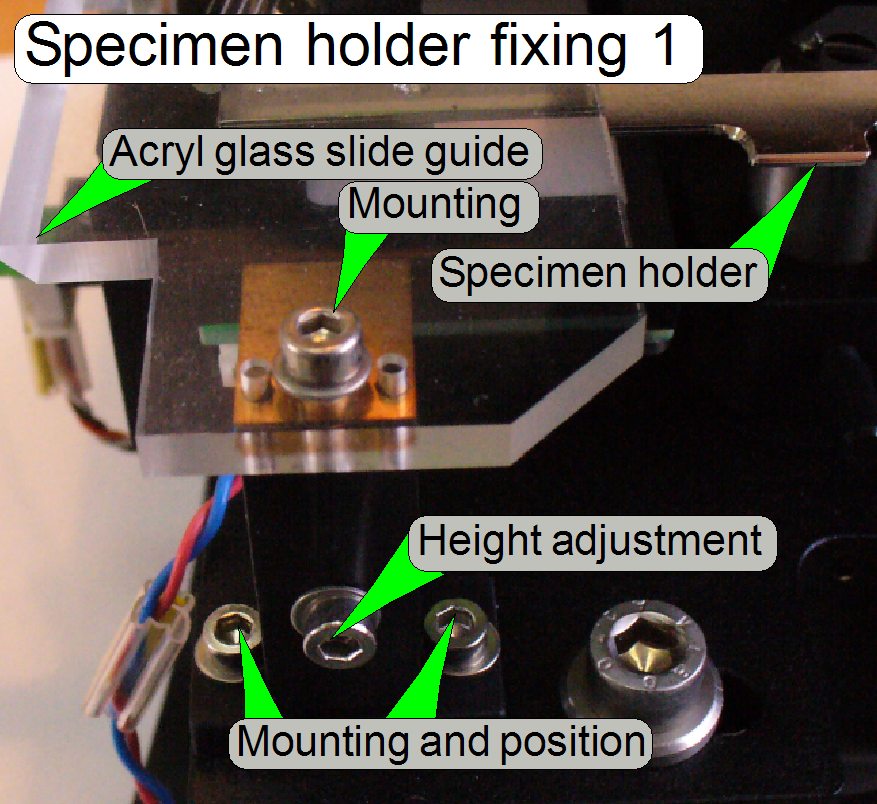
Adjust the specimen holder fixing
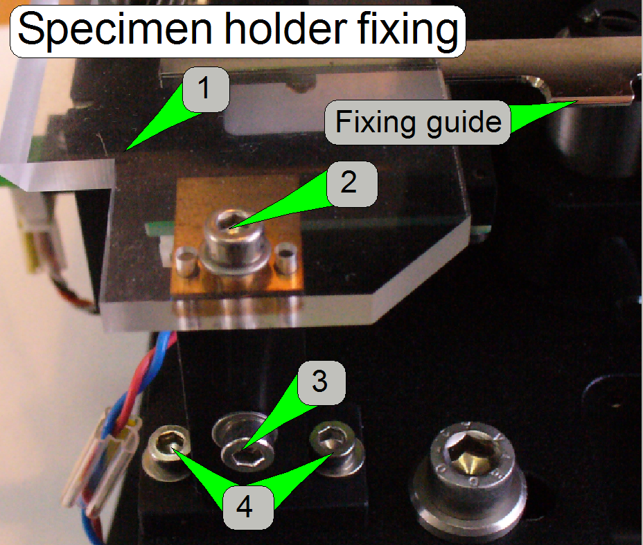
1.
Plexiglas slide leader, and
2.
Mounting; tighten it carefully; the acryl glass can burst easily.
3.
Height adjustment
4.
Position adjustments
Position
adjustment
This adjustment assumes that the scanner plate
position is correct, see above “Adjust the scanner plate position”.
1.
Loosen the bolts (4)
2.
Set the X-Y-stage to the limits Y-min and X-min, (see
also “The X-Y-stage” and “Find the hardware limits for the
X-Y-carriage”).
3.
Position the entire specimen holder fixing so, that
the fixing guide of the specimen holder has a gap of about
Adjust
the height
4.
 Set the X-Y-stage
to X-Home1,2 and Y-Home1,2.
Set the X-Y-stage
to X-Home1,2 and Y-Home1,2.
5.
Insert a slide.
6.
Loosen the height adjustment bolt (3).
7.
Set the focus position to 2400 steps.
8.
Pull the specimen holder carefully upward until the limit
of the parallelogram limiter is reached and tighten the fixing (3); see also
“Parallelogram” in “X-Y-stage unit”.
·
During this
adjustment, the parallelogram must not be strained!
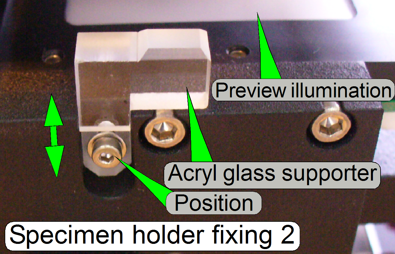
Adjust the supporter on the
left side of the specimen holder
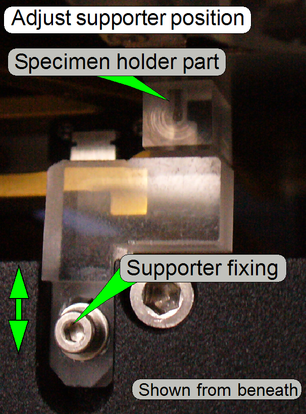 This adjustment
assumes that the supporter on the right side of the specimen holder fixing is
already adjusted.
This adjustment
assumes that the supporter on the right side of the specimen holder fixing is
already adjusted.
9.
Loosen the supporter fixing.
10. Set the X-Y-stage
to X-Home1,2 and Y-Home1,2.
11. Move the supporter
downward, then upward until the supporter part of the specimen holder is
reached; there should be no pressure against the specimen holder.
12. Tighten the
supporter fixing bolt carefully; the acryl glass may
burst easily!
Check the gap between
slide leader and the specimen holder
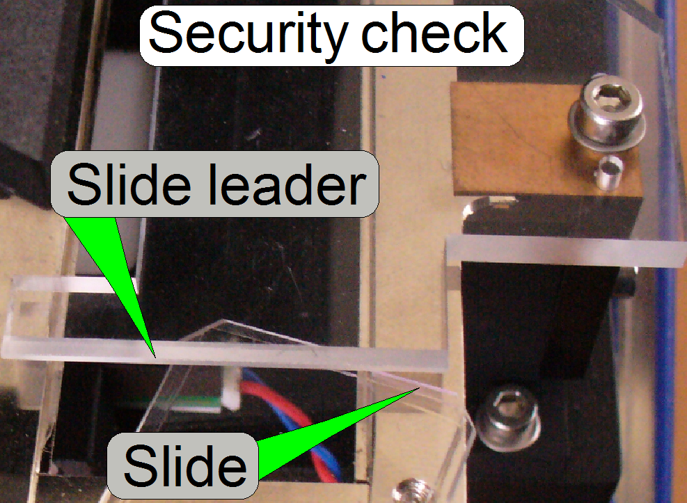 Because the slide
is inserted manually, the acryl glass slide leader limits the gap over the
specimen holder from the top and ensures so, that the slide can not be inserted
wrong or slant.
Because the slide
is inserted manually, the acryl glass slide leader limits the gap over the
specimen holder from the top and ensures so, that the slide can not be inserted
wrong or slant.
·
Check this behavior with a slide. If the slide is
attempt to be inserted any kind else then correct, the manual slide insert
procedure must be inhibited.
Define
the slide insert and remove parameters
The following parameter values defining the slide
insert and remove position for the specimen holder in the DESK. The values are
often 0, it means Home1,2; the values for the parameters “InsertSlide PositionX“, “RemoveSlide PositionX1“, and
“RemoveSlidePositionX2“ can be used to
adjust the specimen holder position to the housing, but the size of the gap is
not critical.
If any value would be more the 1000 steps, the scanner
plate position must be corrected (see above “Adjust the scanner plate
position”).
Relevant
parameters in the file “MicroscopeConfiguration.ini”
The shown values are for information only!
[SlideLoading]
InsertSlidePositionX=200
InsertSlidePositionY1=0
InsertSlidePositionY2=0
InsertSlidePositionY3=0
RemoveSlidePositionX1=200
RemoveSlidePositionX2=200
RemoveSlidePositionY=0