Prerequisites for scanners
For technicians and sales managers!
 These instructions
describe the procedures to cabling Pannoramic scanners with the computer,
executing of set up procedures and installing of different, specified cameras. These
instructions are described and based on the scanner Pannoramic 250, but some
chapters are true for the SCAN,
These instructions
describe the procedures to cabling Pannoramic scanners with the computer,
executing of set up procedures and installing of different, specified cameras. These
instructions are described and based on the scanner Pannoramic 250, but some
chapters are true for the SCAN,
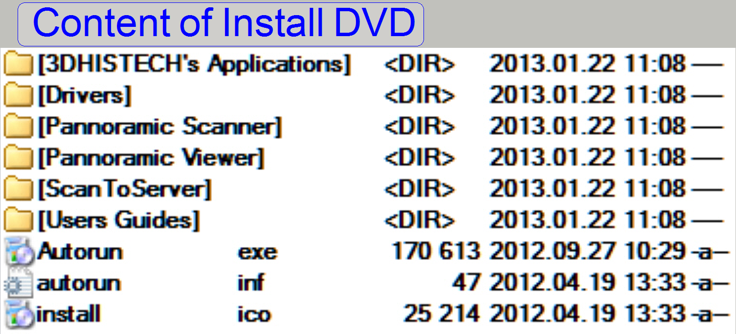
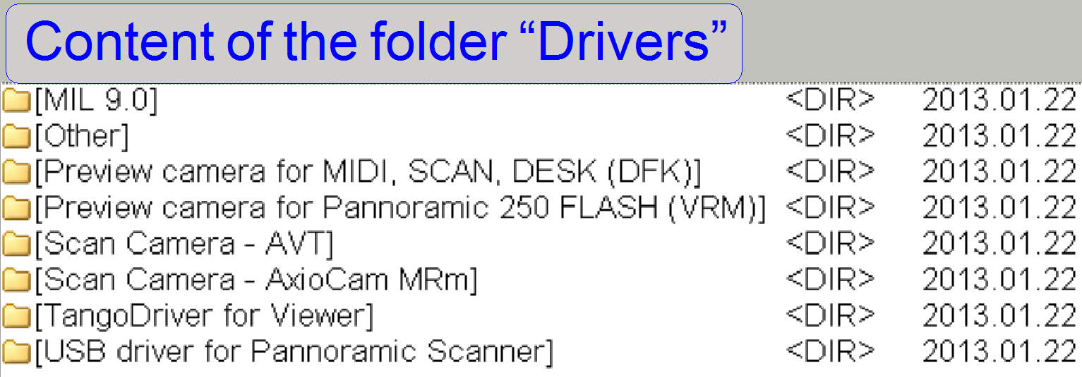
An important part is the correct setup of the drivers and this will be
described also. The driver, needed to install the specified component is found
on the delivered install CD or DVD for the Pannoramic scanner.
The description is based on the software version 1.15 and 1.16 of the
program “SlideScanner.exe”.
· Because since the
software version1.16 here described components and drivers are useable in the
SCAN,

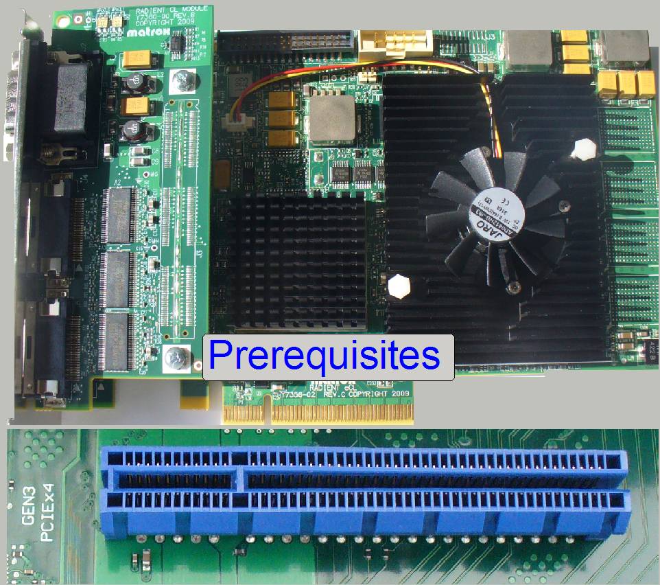
Hardware conditions
and cabling
 The electrostatic
discharge (ESD) is a very harmful occurrence in connection with electronic
devices; it may destroy the device (camera), the interface board or the entire
main board of the computer. Therefore, to avoid ESD, the following precautions should
be abode.
The electrostatic
discharge (ESD) is a very harmful occurrence in connection with electronic
devices; it may destroy the device (camera), the interface board or the entire
main board of the computer. Therefore, to avoid ESD, the following precautions should
be abode.
Important
If the damage of devices, boards or the camera is the
result of ESD, the warranty of the destroyed unit is lost!
Please refer also to: “Precautions” and “Electrostatic discharge”
Handling of extension
cards and electronic devices
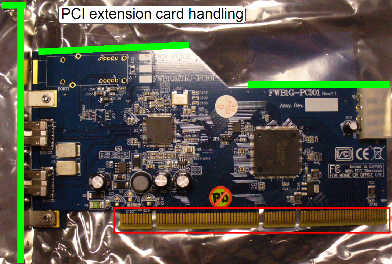 Please refer to: “Precautions”
and “Electrostatic
discharge” and “Handling of
electronic devices”
Please refer to: “Precautions”
and “Electrostatic
discharge” and “Handling of
electronic devices”
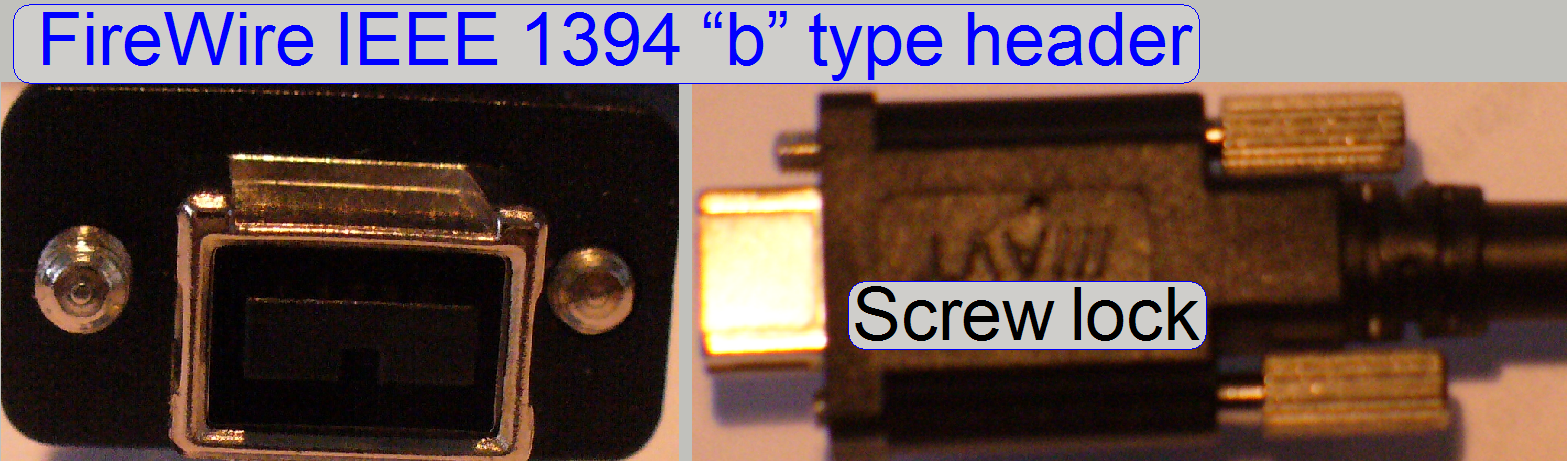
FireWire IEEE 1394 and
the USB interface
.
Please refer to: “Precautions”,
“Electrostatic discharge”
and” FireWire and USB
interface”
To increase the ESD protection for the cameras, please handle the
cameras in the following sequences:
·  Connect the camera
cable always first to the computer; touch the computer housing and then plug
the cable into the camera.
Connect the camera
cable always first to the computer; touch the computer housing and then plug
the cable into the camera.
· If the camera
should be disconnected, touch the computer housing first; unplug the cable from
the camera and only then disconnect the cable from the computer.
Computer
configuration and conditions
Check, update COM port
addresses
 The software
version 1.15 (and following versions) of the program SlideScanner.exe is based
on Windows® 7 x 64bit and requires the following minimal configuration:
The software
version 1.15 (and following versions) of the program SlideScanner.exe is based
on Windows® 7 x 64bit and requires the following minimal configuration:
· Windows 7; the 64bit
version; see: Setup the operating
system Windows® 7 x 64bit
· 80 GB HDD capacity
for the operating system (C-drive SATA III); SW ver. 1.20: 120GB
· 8 GB RAM; SW ver. 1.20: 16GB
·  Quad core Intel
processor; 3 GHz
Quad core Intel
processor; 3 GHz
· Other HDD capacity
to store scanned slides; e.g. 2000GB
· 10 USB port 2.0
(Keyboard and Mouse included)
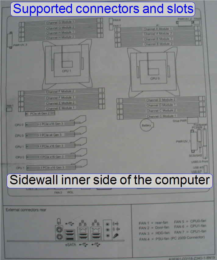
· 1 or 2 Solios
boards (depending on the installed cameras); PCI-e x4 or PCI-e x8 slots or
higher or
· 1 Radient board
(depending on the installed cameras); PCI-e x8 slot
· 1 or 2 FireWire
ports or boards (depending on the installed cameras)
Deviations to lower values may result in slow scan speed; the program
SlideScanner.exe will not start correctly or may freeze.
Video
board and monitor
For best detail visualization of the virtual tissues, the monitor size
and the resolution should be as large as possible; the resolution should be at
least 1024 x 768 pixels.
Today, a full HD
resolution can be accepted as standard.
· 1920 (H) x 1080
(V)pixels; HD 1080p
· Monitor size: 23“ or higher
Following table contains information about mainly used configurations and
components depending on scanner types and software development states.
Shown information
is subject to be changed any time, without notice
Remark
HDD
· Information about
the Operating system’s space is a minimum value, occupied only for the operating
system; the HDD capacity of the C-drive is often much more.
· To store scanned
slides further HDD capacity is required; e.g. 2000GB. Today SATA III 6Gb/s with
large cache RAM size (at least 32MB) type drives with high spinning speed (7200
rpm or higher) should be implemented.
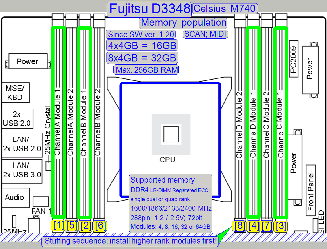
RAM
· Information about
the capacity of RAM memory is the minimum value, it means, with this value the
scan program and the viewer program is working. To reach highest scan speeds,
the RAM capacity should be twice the minimum value (recommended). Recommended
values are shown in parentheses. This is very important if the configuration
contains Matrox SOLIOS or RADIENT or CoaXPress type interface boards.
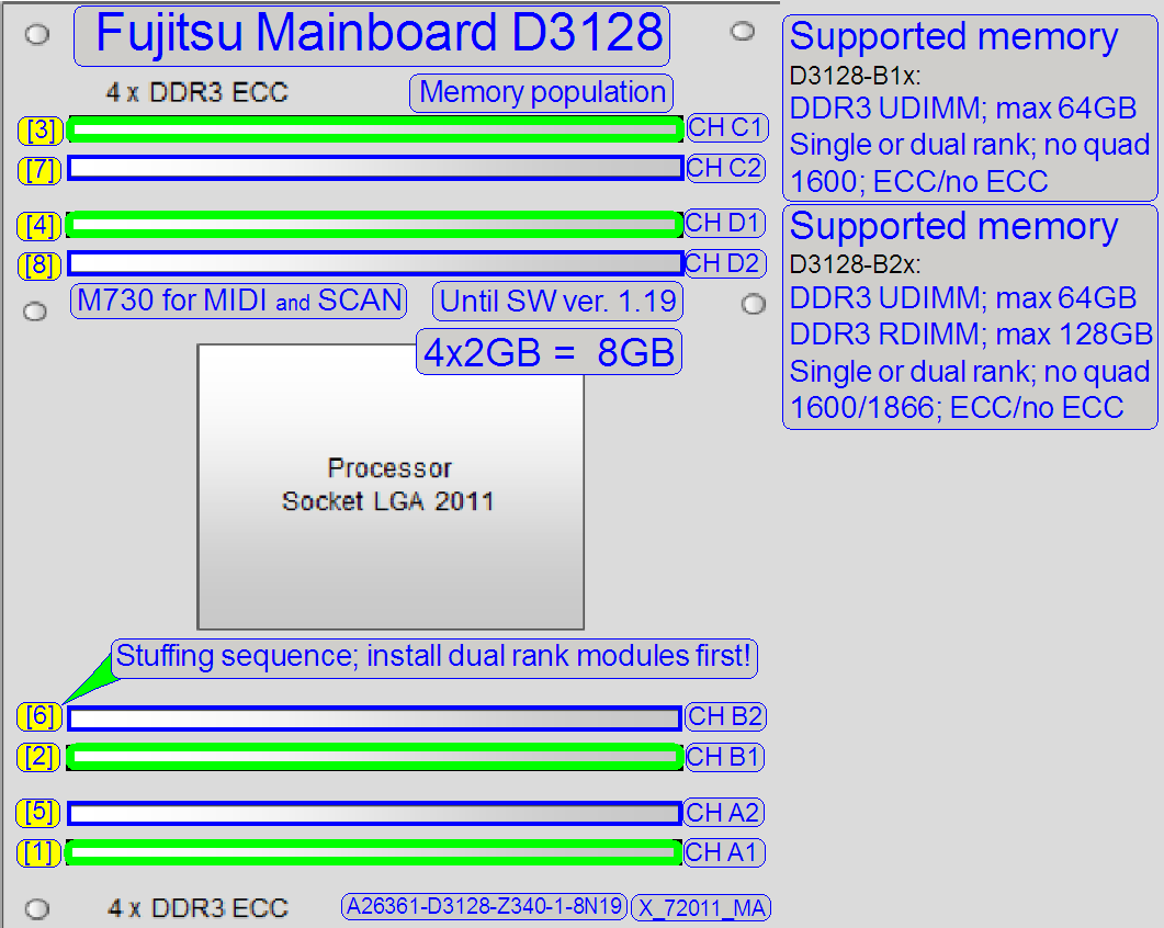
Furthermore, it is important for the system speed to equip RAM slots with memory
modules as much as possible if single channel modules are used; it means, if
the required RAM capacity can be reached by the available RAM slots with 2GB
and 4GB RAM modules, the 2GB version should be preferred (depends mainly on the
used Main board)!
· Use memory modules
with the highest FSB frequency, if possible
· Use multi-channel
RAM modules with higher capacity, if possible!
|
Main board |
Version |
SW version |
Scanner
type |
RAM Population (recommended) |
Configure |
Op.
system Size (min) |
User’s manual (stored) |
|
|
Board |
Computer |
|||||||
|
FUJITSU CELSIUS;
R-series |
||||||||
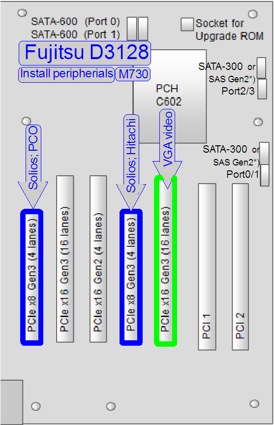
|
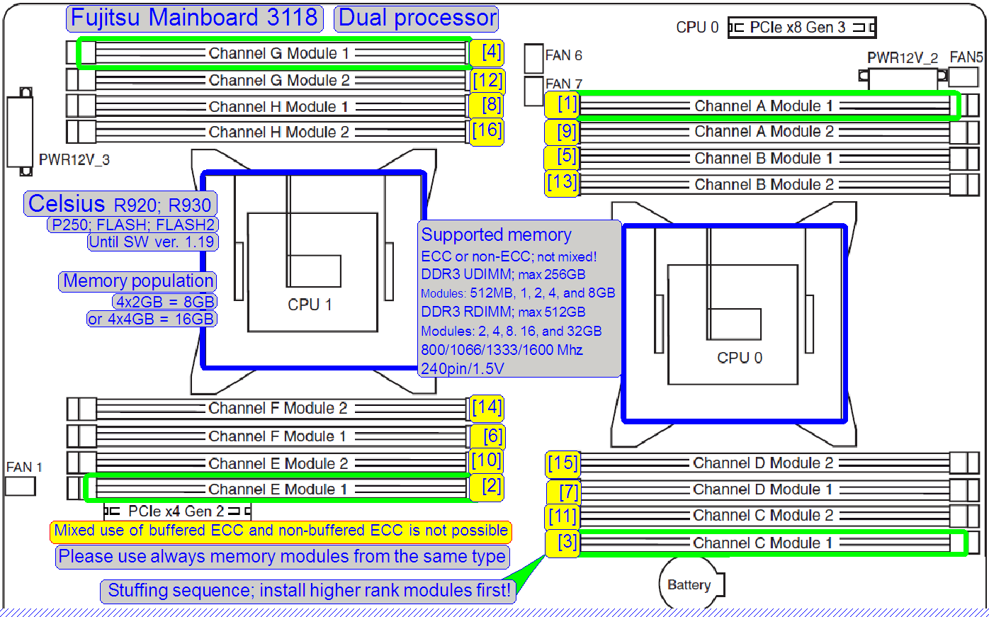
D3118 |
Until 1.19 |
P250, Flash
Flash2; PCON |
Solios |
80GB |
|
|||
|
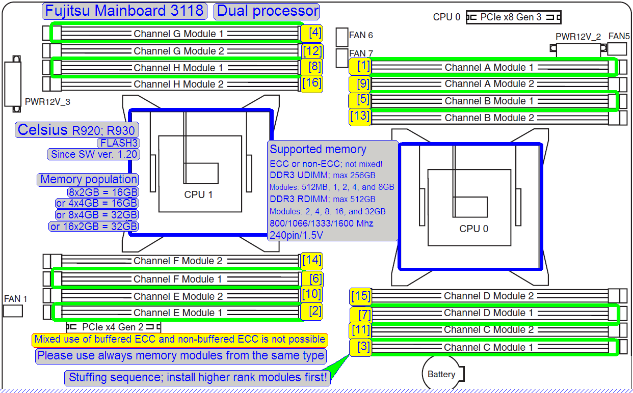
D3118 |
80GB |
|
||||||
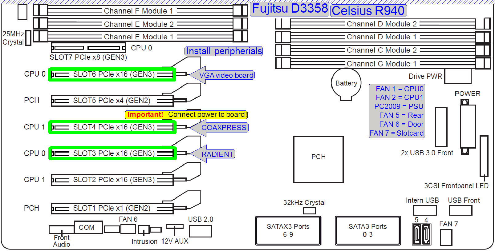
|
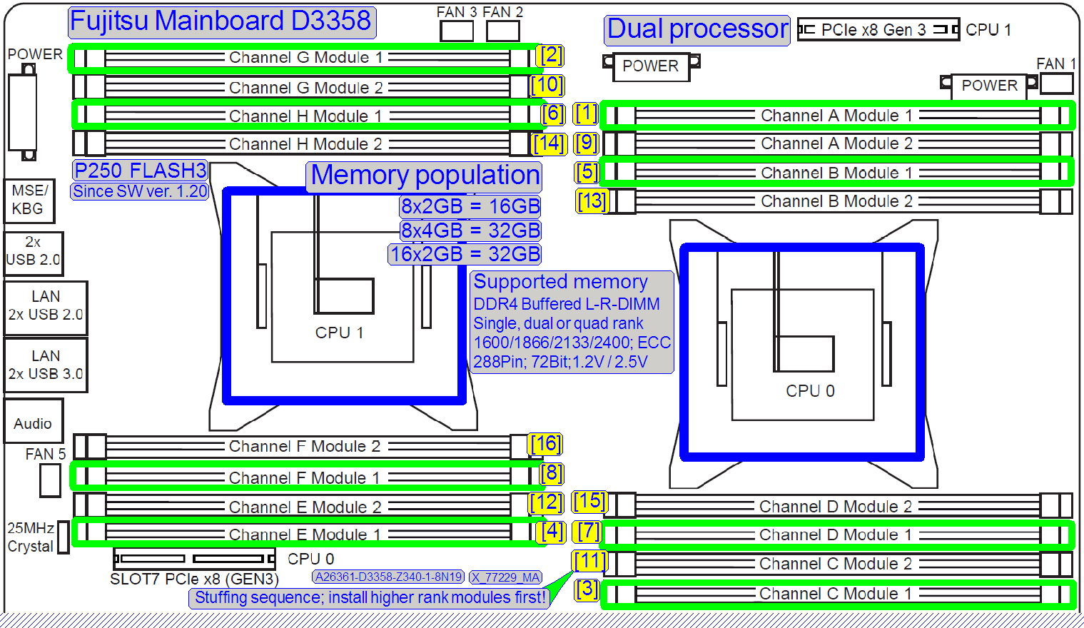
D3358-B |
Since 1.20 |
Flash3 |
16GB (32GB) |
120GB |
|
|||
|
|
||||||||
|
FUJITSU CELSIUS;
M-series |
||||||||
|
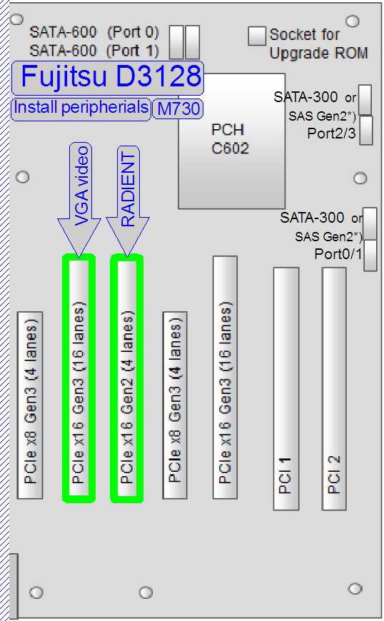
D3128-B |
Until 1.19 |
SCAN; |
|
80GB |
|
|||
|
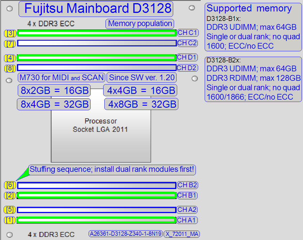
D3128-B |
80GB |
|
||||||
|
Since 1.20 |
16GB (32GB) |
120GB |
D3348 |
|||||
|
|
||||||||
|
FUJITSU ESPRIMO;
P-series |
||||||||
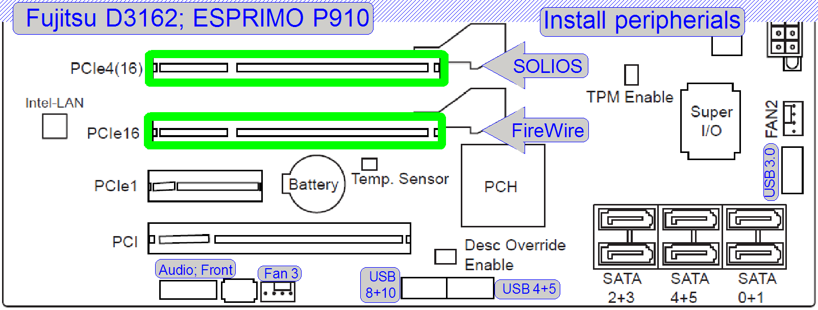
|
D3162 |
Until 1.19 |
DESK |
4GB (8GB) |
80GB |
||||
|
Until 1.19 |
4GB (8GB) |
|
80GB |
|||||
|
|
910, 920 |
Since 1.20 |
8GB (16GB) |
|
120GB |
|
|
|
|
Remark: Other
main boards can be found on the Fujitsu home page; Product selection (manually
search) |
||||||||
|
See also: Multi
channel RAM; Memory
Rank; PCI-express;
Solios board; Radient board; CoaXPress board; Useable cameras |
||||||||
·  More
detailed information about useable computer configuration regarding the scanner
type and software version can also be asked from our service and support center.
More
detailed information about useable computer configuration regarding the scanner
type and software version can also be asked from our service and support center.
 E.g. into a
computer “Fujitsu Model: ETNA –S– D3128”
E.g. into a
computer “Fujitsu Model: ETNA –S– D3128”
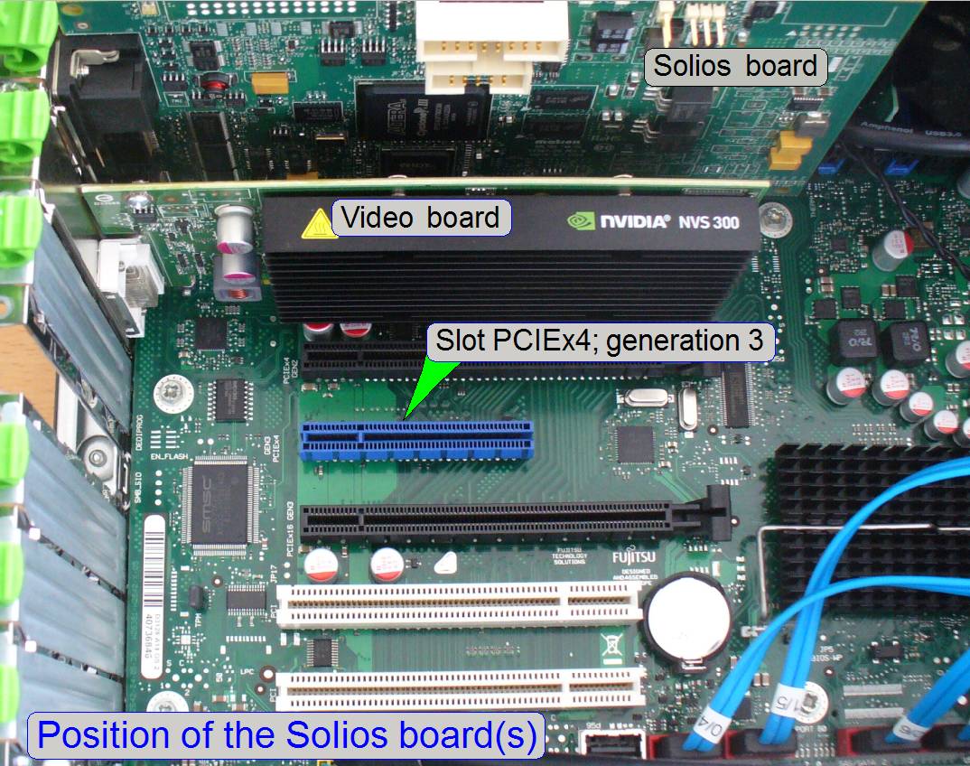
· Depending on the
computer, deviations from the following sequence may occur!
·
Read the passage of “Electrostatic discharge”
·
Disconnect the power cord
·
Open the cover.
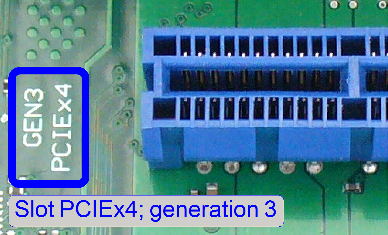
·
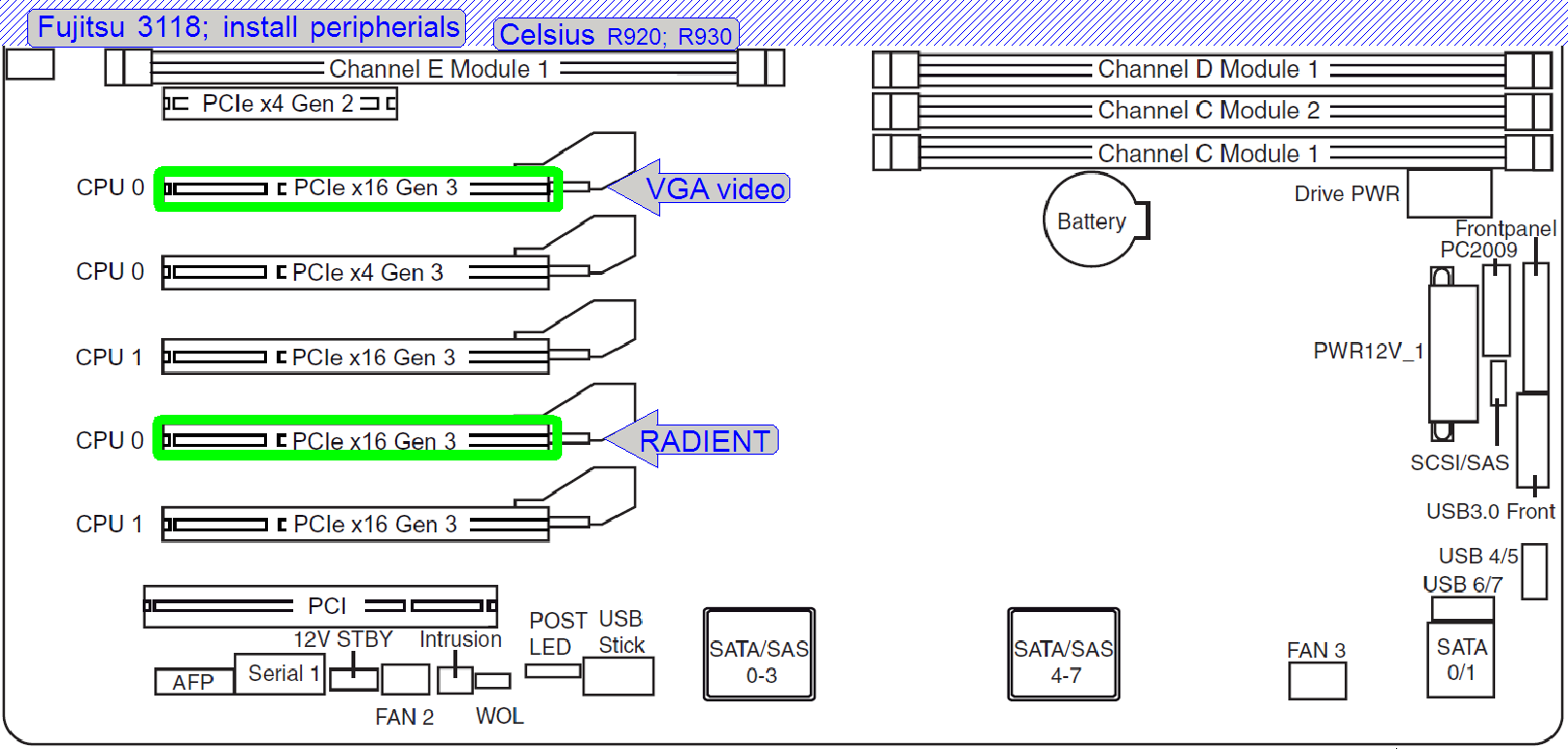
Find the two slots PCIEx4;
Generation 3; marked with blue color.
·
Unpack the Solios board.
·
Insert the Solios board into a slot PCIEx4; Generation 3.
·
 Unpack
the second Solios board (if required).
Unpack
the second Solios board (if required).
·
Insert the second Solios board into a slot PCIEx4; Generation 3.
·
Drive in the security bolts of both
boards.
·
Close the cover.
·
Connect Power and cables.
·
Switch on the computer and check the
functionality.
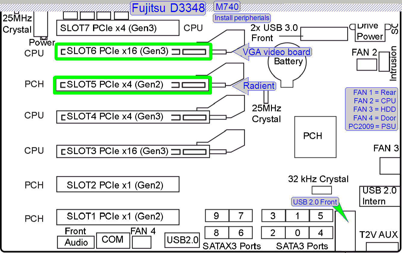
Install the FireWire board or other PCI-e x4 boards
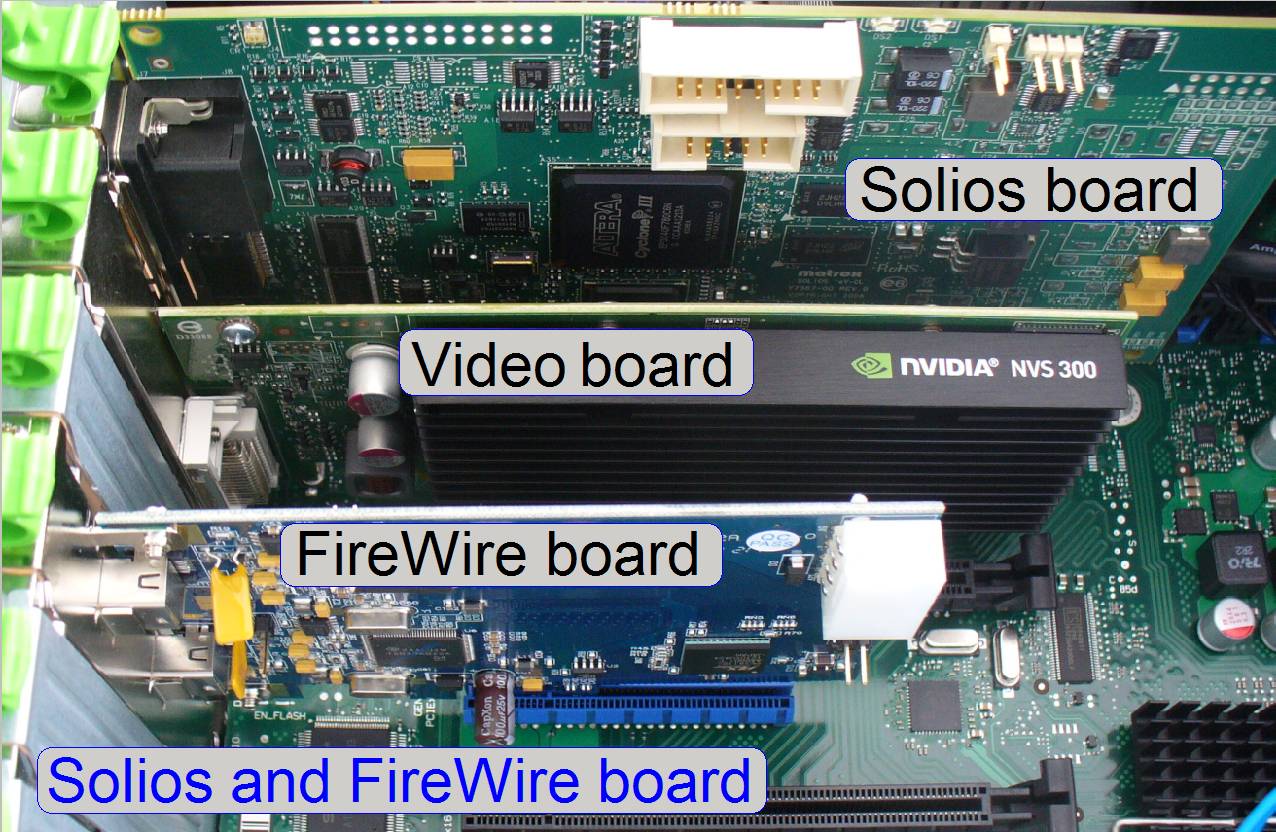 E.g. into a computer
“Fujitsu Model: ETNA –S– D3128”
E.g. into a computer
“Fujitsu Model: ETNA –S– D3128”
· Depending on the computer
and the interface type of the FireWire board, deviations from the following
sequence may occur!
· Read and follow
the instructions of the passage “Electrostatic discharge”
· Disconnect the
power cord
· Open the cover.
· Find the slot PCI-e x4; Generation 3; marked with blue color.
· Unpack
the FireWire board.
· Insert
the board into a slot PCI-e x4; Generation 3.
· Drive
in the security bolt of the board.
· Close
the cover.
· Connect
Power and cables.
· Switch
on the computer and check the functionality.
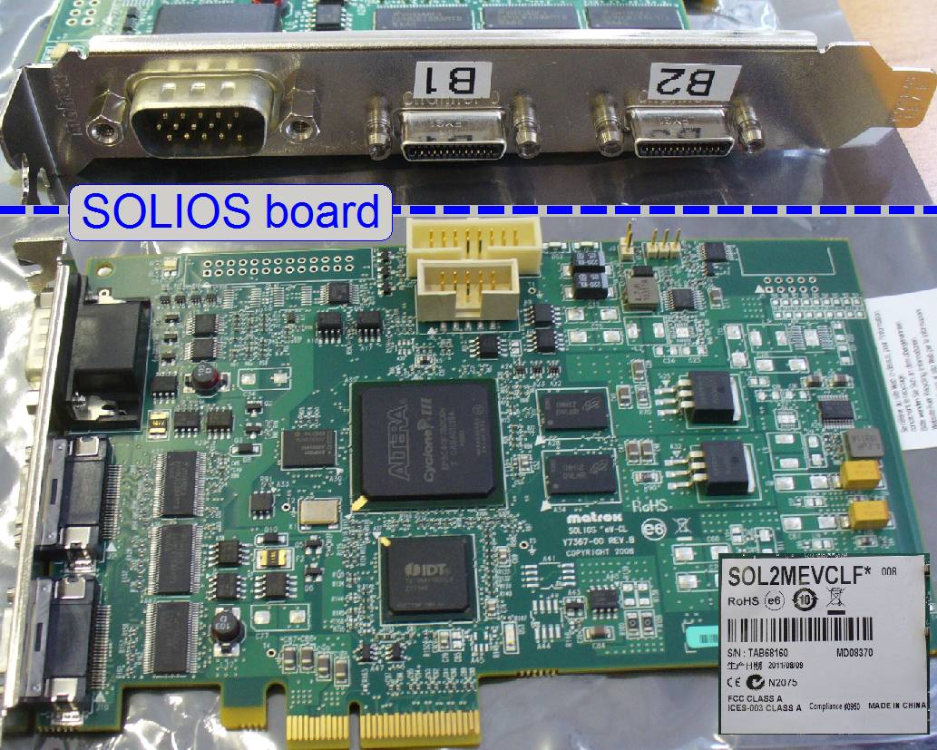
The board uses a PCIe x4
slot of the computer, and is equipped with 256 or 512 MB DDR SDRAM and 2 Camera Link SDR26 (CL mini)
connectors.
· The grabber card
is used to interface “Camera Link” interfaced scan cameras, like
· the camera
CIS-VCC-F52U25CL or
· the camera pco.edge respectively.
· If two cameras
have to be connected at the same time, two grabber cards must be inserted into
the computer; one for each camera.
·  By default, the
CIS-camera (BF scan camera) is connected to the ports, named as A1 and A2; the
pco.edge camera (FL scan camera) is connected to the ports, named as B1 and B2.
By default, the
CIS-camera (BF scan camera) is connected to the ports, named as A1 and A2; the
pco.edge camera (FL scan camera) is connected to the ports, named as B1 and B2.
· The hardware and
software installation of the grabber card “SOL2MEVCLF*” should be done by a qualified system administrator; please contact your information
technology support group.
1.
The software setup procedures can be found in the
section “Software
and driver installation” and in the chapter “Setup_MIL_9”.
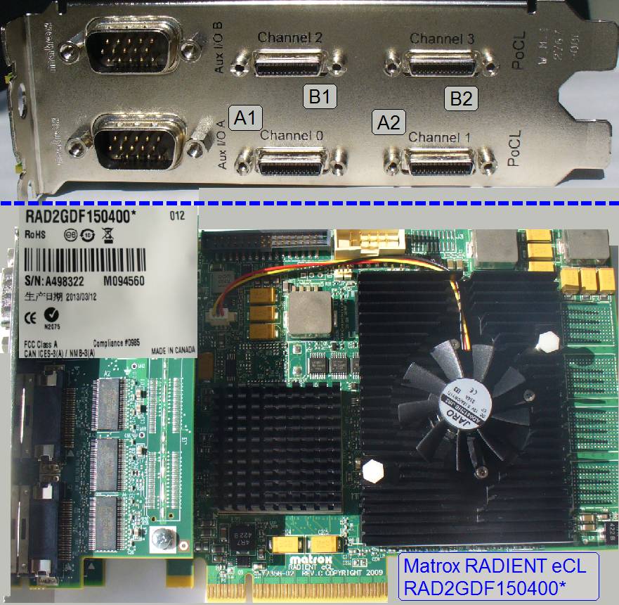 The board uses a PCIe x8 port of the computer and is
equipped with max. 4GB DDR2 RAM, up to 32MB of QDR2 250 SRAM and 4 Camera Link HDR26 (CL mini)
connectors.
The board uses a PCIe x8 port of the computer and is
equipped with max. 4GB DDR2 RAM, up to 32MB of QDR2 250 SRAM and 4 Camera Link HDR26 (CL mini)
connectors.
The maximal data transfer rate is:
· Host
interface PCIE®
2.0 x8
·
4GB of DDR2 RAM 10.6GB/s read and write speed.
·
32MB of QDR2 250 SRAM 4GB/s
read and 4GB/s write speed
· The grabber card
is used to interface
·  the camera CIS VCC-FC60FR19CL
and
the camera CIS VCC-FC60FR19CL
and
· the
camera pco.edge or any
other CL-interfaced camera.
· The board is able
to handle both cameras at the same time; only 1 grabber card is required.
· By default, the
CIS-camera is connected to the ports, named as A1 and A2; the pco.edge camera
is connected to the ports, named as B1 and B2.
· The hardware and
software installation of the grabber card “Matrox
RADIENT eCL” should be done by a qualified system
administrator; please contact your information technology support group.
· The software setup
procedures can be found in the section “Software and driver
installation” and in the chapter “Setup_MIL_9”.
More information about the grabber card RADIENT
eCL can be found in Matrox® “RADIENT eCL” (pdf; stored)
And on the Matrox home page.
http://www.matrox.com/imaging/en/products/vision_processors/radient/
Check and update the COM
port addresses
Important
 After installing
the MIL 9.0 for the RADIENT board, please check the COM port address
distribution for the RADIENT board.
After installing
the MIL 9.0 for the RADIENT board, please check the COM port address
distribution for the RADIENT board.
· Please connect always
the BF scan camera to the Camera link channels 0 and 1 of the RADIENT board.
The camera link channels 0 and 1 creates the channel 0 of the RADIENT board
· Please connect
always the FL scan camera to the Camera link channels 2 and 3 of the RADIENT
board. The camera link channels 2 and 3 create the channel 1 of the RADIENT
board.
· In all cases, the
COM port number, issued for the RADIENT board channel “
Please check:
· (BF scan camera)
RADIENT board channel “
Only if
these conditions are met, the scan software SlideScanner.exe will start
correctly!
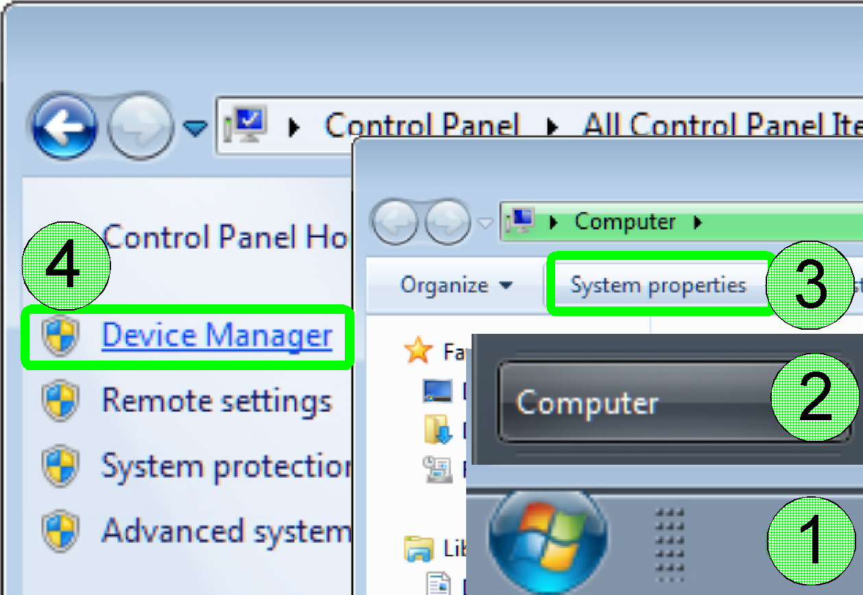
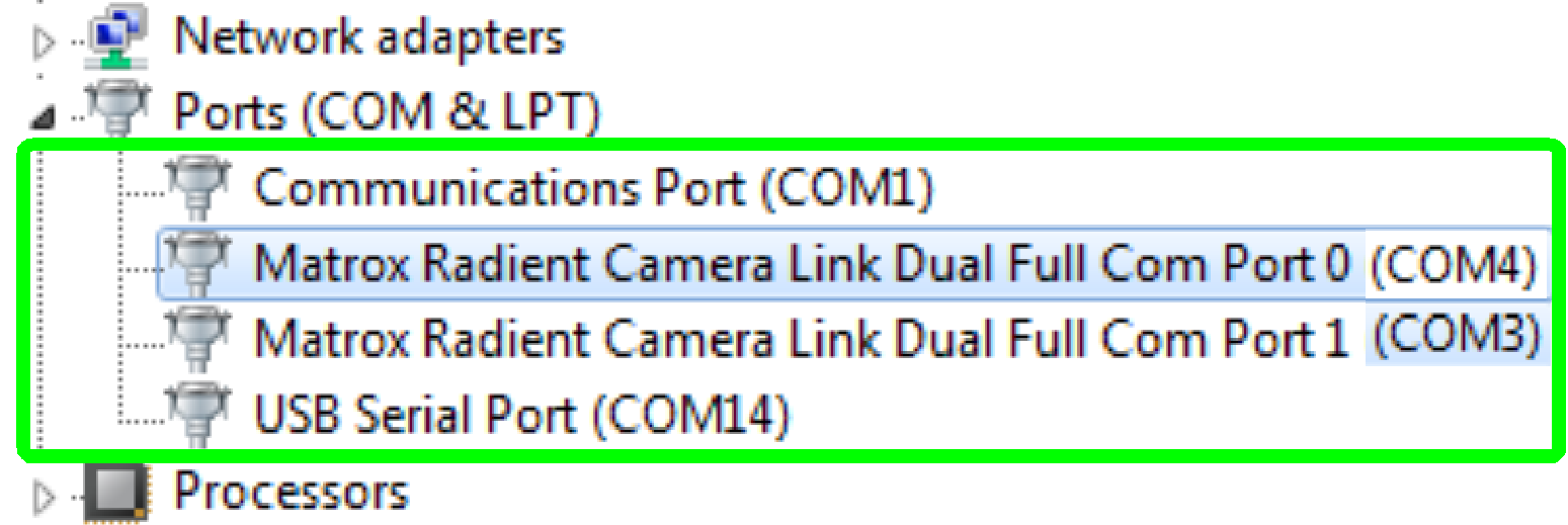
Start the “Device manager”
·
Press “Start”(1), “Computer”(2), “System
properties”(3),and “Device Manager”(4).
COM
port addresses of the RADIENT board
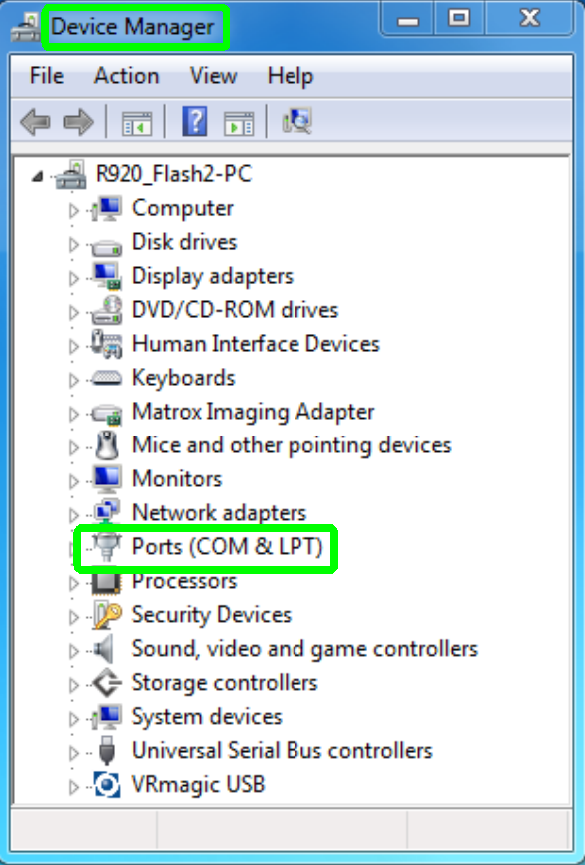
· By double click on
the item “Ports (COM & LPT)” the submenu will be opened
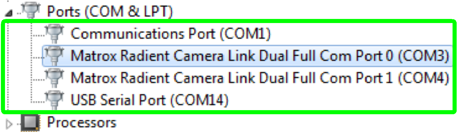
Check
the com port address
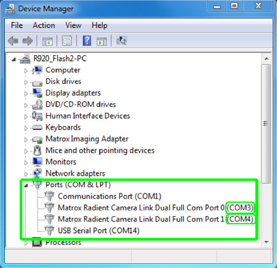 As shown on the
right, the RADIENT board channel “
As shown on the
right, the RADIENT board channel “
The lumencor spectra’s port address is COM14.
Because the requirement
· RADIENT board
channel “
is fulfilled, modifications of the COM port addresses are
not required!
In this example, only the COM port addresses 1, 3, 4 and 14 are used;
other addresses are not occupied.
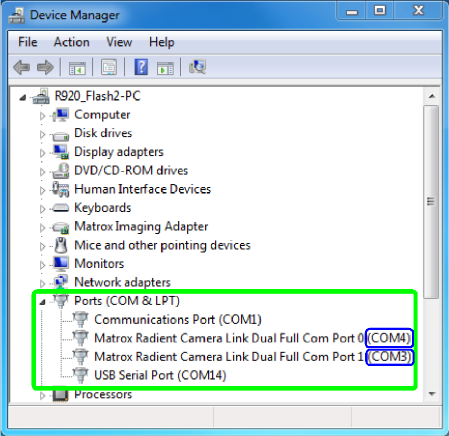
· As shown on the
right, the RADIENT board channel “
Because the requirement
·
RADIENT board channel “
is not fulfilled, modifications of the COM port addresses are
required!
·
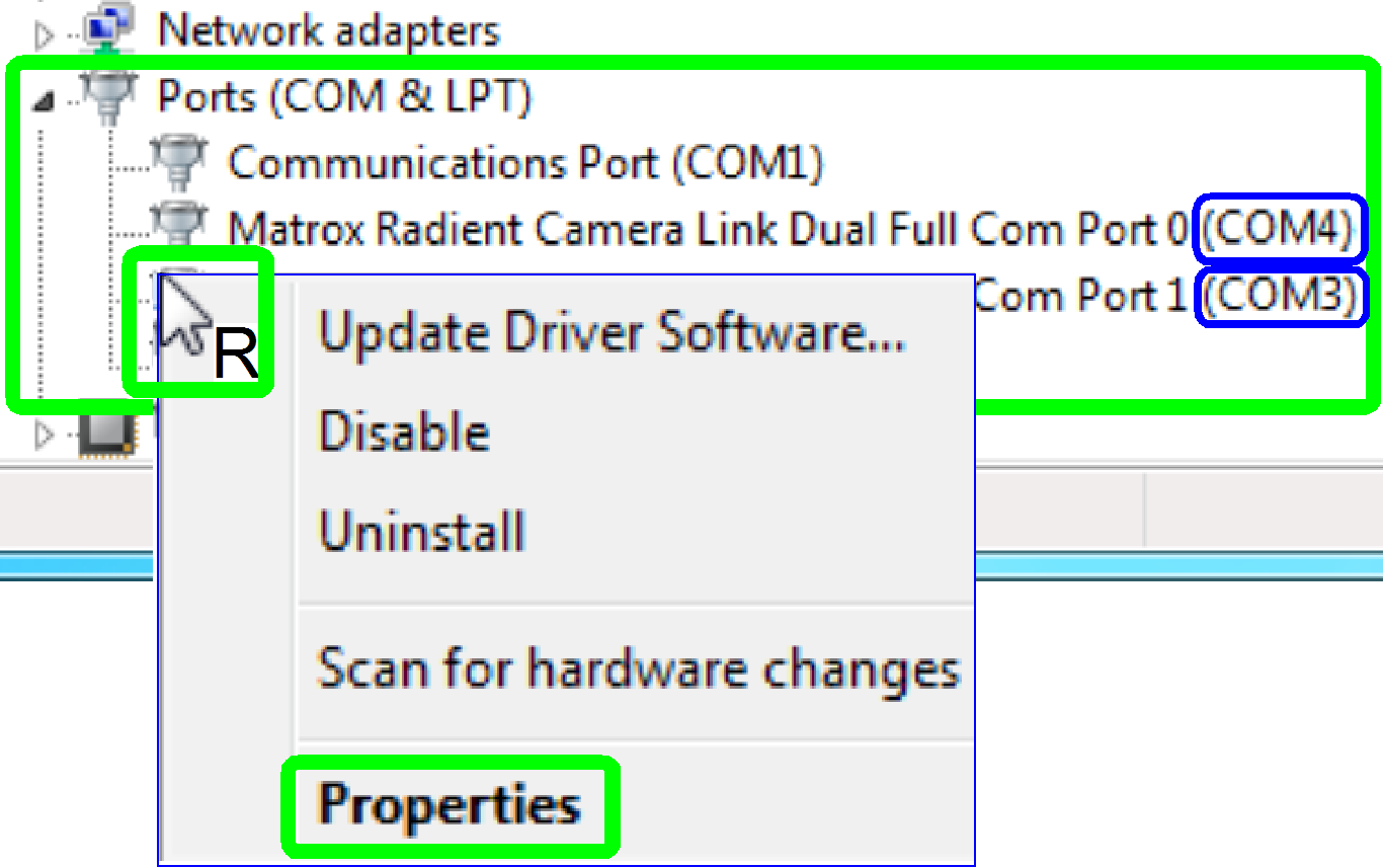 With right click
in the line of the COM port address to be modified, a pull down menu will be
opened
With right click
in the line of the COM port address to be modified, a pull down menu will be
opened
·
Click on Properties
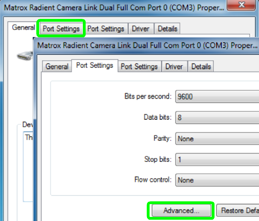
· Select “Port Settings”
and “Advanced …” next
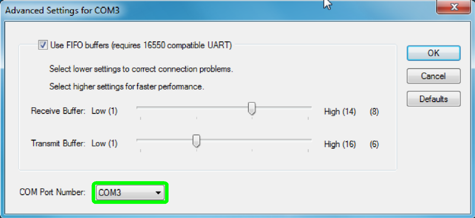
In the window “Advanced Settings for COMxx” open the pull down menu “
 In our example, the
port number 3 should be modified to the port number 5 to fulfill our
requirement:
In our example, the
port number 3 should be modified to the port number 5 to fulfill our
requirement:
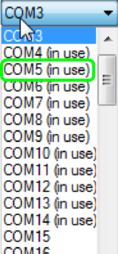
·
RADIENT board channel “
·
Addresses, shown as “in use” are not all true!!
 In this example,
only the COM port addresses 1, 3, 4 and 14 are used; other addresses are not
occupied.
In this example,
only the COM port addresses 1, 3, 4 and 14 are used; other addresses are not
occupied.
· The “TaskManager”
shows the really occupied addresses!
· In our example,
modify the port address from “COM3” to the port address “COM5”.
Remark
It is also possible to modify the port address from “COM4” to the port
address “COM2”; the result would be also correct.
Important is only, that the final port address is momentarily not
occupied by another unit and the following requirement is fulfilled!
·
RADIENT board channel “
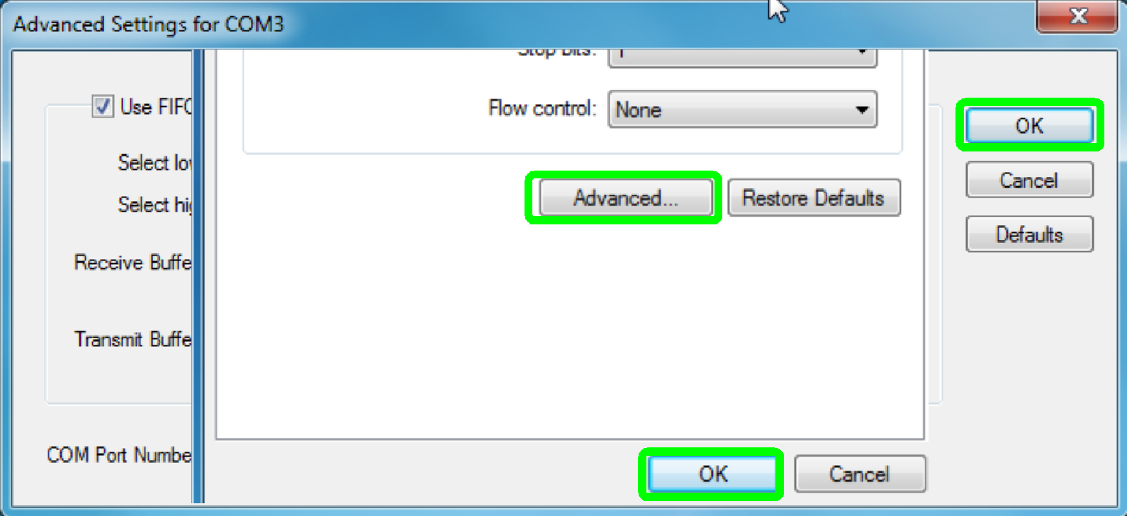
Close all dialogues with “OK”
Important
Please restart the computer!
End of procedure
Compare Radient and Solios
board
|
Compare Matrox Frame Grabbers |
||
|
Parameter |
Matrox Radient eCL |
Matrox Solios eV-CL |
|
Form Factor |
▪ PCIe® 1.0 x8 |
▪ PCI-X ® |
|
Acquisition Format |
▪ frame or line scan |
▪ frame or line scan |
|
Acquisition Rate |
▪ up to 85 MHz |
▪ up to 85 MHz |
|
On-board Processing |
▪ Altera® Stratix® III Processing FPGA with
110K up to 320K logic elements and 133 MHz operation |
▪ Bayer (2x2 average) interpolation
(eV-CLB/CLBL) |
|
Memory |
▪ up to 32MB SRAM ▪ 2 GB SDRAM |
▪ 256 MB |
|
Additional Features |
▪ video synchronization (including trigger
input and exposure output) and auxiliary digital I/Os |
▪ video synchronization (including trigger
input and exposure output) and auxiliary digital I/Os |
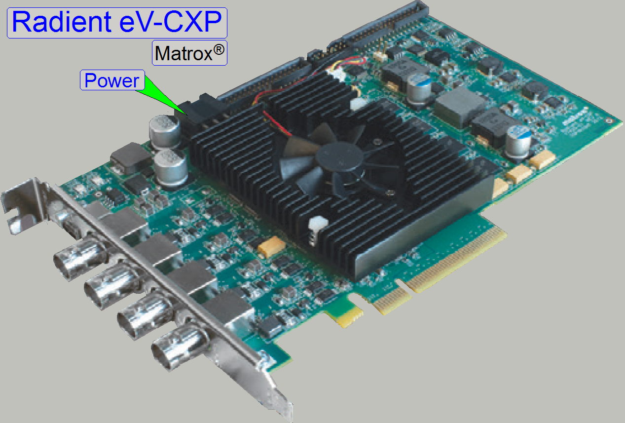 The Matrox Radient
eV-CXP CoaXPress board contains 4 coax BNC connectors with a transfer rate of
up to 6.25Gbit/s on each connector simultaneously.
The Matrox Radient
eV-CXP CoaXPress board contains 4 coax BNC connectors with a transfer rate of
up to 6.25Gbit/s on each connector simultaneously.
Power supply of the camera is realized as PoCXP, this means, the power
for the camera is provided over the coax cable. If one camera is connected to a
single coax line the provided power is 13W max. To use the high bandwidth
capability of the interface board, one camera may use all four lines and so a
transmitting rate of 25Gbit/s can be reached.
· Host
interface PCIE®
2.0 x8
· Transfer
rate 4GB/s max.
· Memory 4GB max. SDRAM
on board
· Image
preprocessing
·  Bayer interpolation
· Color space interpolation
· LUT mapping
 More detailed
information can be found in
More detailed
information can be found in
CoaXPress frame grabber Matrox “RADIENT eV-CXP” (pdf; stored)
· If the LED of any
wire is flashing red, then the appropriate line is not recognized or not
connected or the line is not controlled yet by software!
Important
To provide power for the camera the internal power connector has to be
connected with the power supply!
|
Compare Matrox Frame Grabbers |
||
|
Parameter |
Matrox Radient eCL |
Matrox Radient eV-CXP |
|
Form Factor |
▪ PCIe® 1.0 x8 |
▪ PCIe® 2.0 x8 |
|
Acquisition Format |
▪ frame or line scan |
▪ frame or line scan |
|
Acquisition Rate |
▪ up to 85 MHz |
§
up to 6.25 Gbps (CXP-6) per
connection §
up to 25 Gbps using four
connections |
|
On-board Processing |
▪ Altera® Stratix® III Processing FPGA with
110K up to 320K logic elements and 133 MHz operation |
▪ Bayer (2x2 average) interpolation |
|
Memory |
▪ up to 32MB SRAM ▪ 2 GB SDRAM |
▪ 1 GB |
|
Additional Features |
▪ video synchronization (including trigger
input and exposure output) and auxiliary digital I/Os |
▪ video synchronization (including trigger
input and exposure output) and auxiliary digital I/Os |
Note(s):
1. With model supporting Quad CXP.
Manufacturer: FRESCO
LOGIC
Type: FRESCO
FL 1100EX
Sub-type: U3-PCIE
1XG211 Quad port host controller
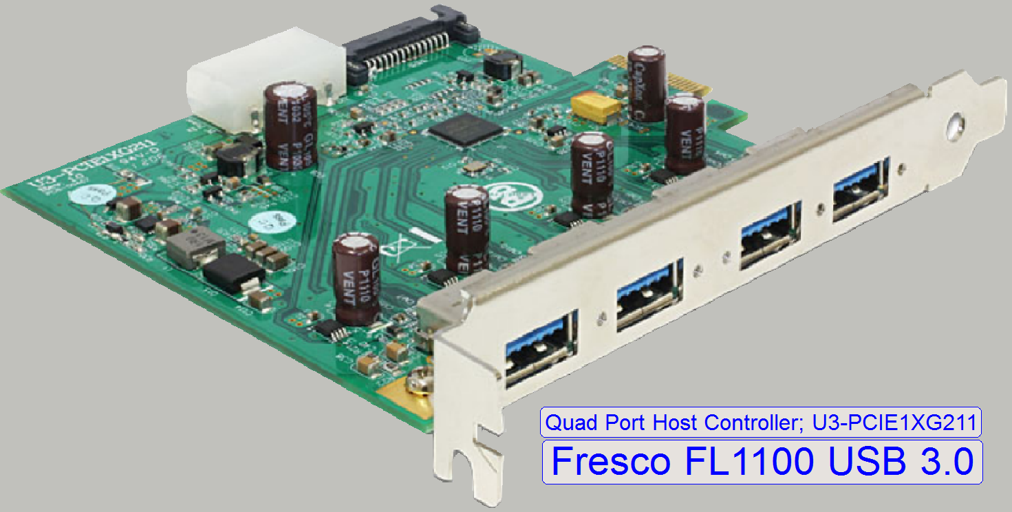 Interfaces: PCI-e 2.0 to USB 3.0 and vice
versa
Interfaces: PCI-e 2.0 to USB 3.0 and vice
versa
Powering: Interface
power over SATA III or IDE power cable
Connections
PCI-e 2.0 compatible
host controller board with USB 3.0 connectors
USB 3.0 with
a transfer rate of up to 5Gbps; it is theoretically 10 times faster than USB
2.0.
Important
Please use always a FRESCO FL 1100 USB 3.0 interface board, type
U3-PCIE1XG211 to interfacing Grasshopper3 type cameras in Pannoramic Scanners.
·
By using other USB 3.0 interface ports, the camera
might not work.
![]() Camera Grasshopper 3
Camera Grasshopper 3
FRESCO LOGIC
Homepage
Power supply
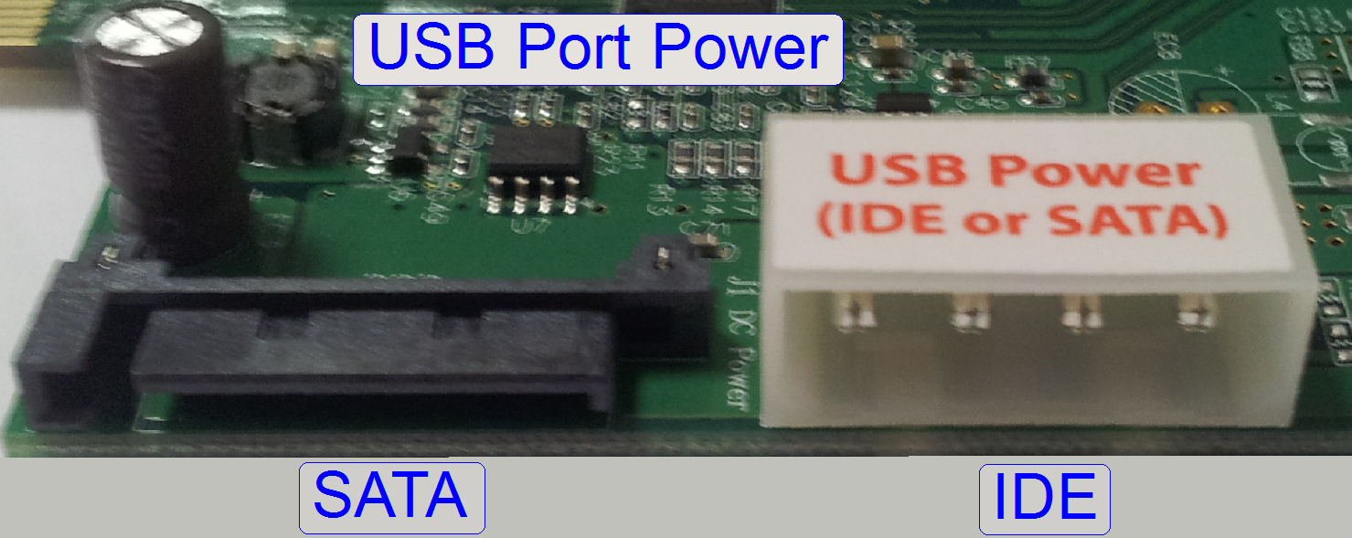 Power for the
camera is provided over USB 3.0
Power for the
camera is provided over USB 3.0
·
To supply the power for the USB 3.0 ports, please
connect an IDE or SATA power cable to the interface board!
Driver setup
Software and driver
installation
This chapter explains the setup procedures of the required software, starting
from the implementation of a new, no formatted HDD until the first slide can be
scanned.
The installation of any part
of the software and hardware components and the drivers should be done by a
qualified member of the information technology support
group (system administrator).
·
The shown procedures are based on the operating
system Windows® 7 x 64bit and the software version
1.16; except otherwise specified explicitly.
The
procedure includes
 Setup Windows 7; the 64 bit version
(clone the operating system)
Setup Windows 7; the 64 bit version
(clone the operating system)
Setup the MIL 9.0 with
service pack SOLIOS board
Setup the MIL 9.0 with
service pack RADIENT eCL board; SW version 1.17
Setup the program
“Slide Scanner”; version 1.15 or higher
Setup the program
“Slide Viewer”.
If an upgrade of a component
should be done, not required steps of the sequence can be left out.
Depending on the installed
SOLIOS or RADIENT board, MIL9.0 is only 1 time installed, together with the
appropriate interface board type!
Setup the operating
system Windows® 7 x 64bits
This chapter contains important information about the operating system
Windows® 7 x 64bits, used with ALL Pannoramic scanners and the Pannoramic viewer!
Operate the software “Slide
Scanner” and “Slide Viewer”

Requirements
· The install package
Windows® 7 x 64bit professional; English (US) version or
· The install package
Windows® 7 x 64bit enterprise; English (US) version
· After installing
the operating system the appropriate version should be upgraded with the
service pack 1 (SP1); if not included.
· Keep the operating
system always up to date by enabling update and refresh options in the
operating system.
Important
Our software “Slide scanner” and “Slide viewer” are
developed and tested with the named operating systems. Other localizations of
windows are not recommended and not supported!
· Deviations
from the language packages may result in incompatibility with our software and
must not be used in conjunction with software products of 3DHISTECH.
Clone the operating system Windows® 7
x 64bit
This procedure
(or any equivalent procedure) is required if:
 The computer is brand new
(without operating system) or
The computer is brand new
(without operating system) or
An upgrade from the software
version 1.14 (operating system Windows® xP) to the software version 1.15 or higher
(operating system Windows® 7 x 64bit) is done.
Important
Please install always only verified and tested versions and
localizations of Windows® 7 x 64bit; see: Setup the operating system Windows® 7 x
64bit
·
An example of the clone
procedure of the operating system Windows® 7 x 64bit onto an empty HDD is shown
in the chapter Clone the
operating system with “Clonezilla”
Now system updates may be
enabled.
 The Matrox Imaging Library
version 9.0 (MIL 9) is used to interfacing the camera link interfaced cameras
like CIS-VCC-F52U25CL and PCO.edge via the
Solios board and allows the detection and analyzing of barcodes; it fulfills
the following tasks:
The Matrox Imaging Library
version 9.0 (MIL 9) is used to interfacing the camera link interfaced cameras
like CIS-VCC-F52U25CL and PCO.edge via the
Solios board and allows the detection and analyzing of barcodes; it fulfills
the following tasks:
· Barcode
reading (only); dongle and license required
and
· Driving
the Solios board(s); the presence
of the board(s) is required during the setup procedure.
Remark
The cameras CIS and PCO.edge
are fully handled by the scan software “SlideScanner.exe” via the Solios board(s);
therefore, an explicit driver installation procedure is not required for these
cameras.
Important
The Matrox Imaging Library
version 9.0 has to be installed prior to the program Slide Scanner. Is the
program slide scanner already installed, install the Matrox Imaging Library
version 9.0, then remove the program slide
Scanner and install it again!
To setup the driver, execute the steps as described in
the chapter “Setup_MIL_9_SOLIOS”
Setup MIL 9.0; RADIENT eCL board; SW
version 1.17
The Matrox Imaging
Library version 9.0 is used to interfacing the camera link interfaced cameras
like CIS- VCC-FC60FR19CL or CIS-VCC-F52U25CL and PCO.edge via the board “RADIENT
eCL” and allows the detection and analyzing of barcodes; it fulfills the following
tasks:
· Barcode
reading (only); dongle and license required
and
· Driving
the board
“RADIENT eCL”; the
presence of the board is required during the setup procedure.
Remark
The cameras CIS and PCO.edge
are fully handled by the scan software “SlideScanner.exe” via the board
“RADIENT eCL”; therefore, an explicit driver installation procedure
is not required for these cameras.
Important
The Matrox Imaging Library
version 9.0 has to be installed prior to the program Slide Scanner. Is the
program slide scanner already installed, install the Matrox Imaging Library
version 9.0, then remove the program slide
Scanner and install it again!
To setup the driver, execute the steps as described in
the chapter “Setup_MIL_9_RADIENT” (not available; not created yet)
The steps are very similar to
the setup steps of the SOLIOS board; please refer to “Setup_MIL_9_SOLIOS”
Driver of the preview camera VRmagic
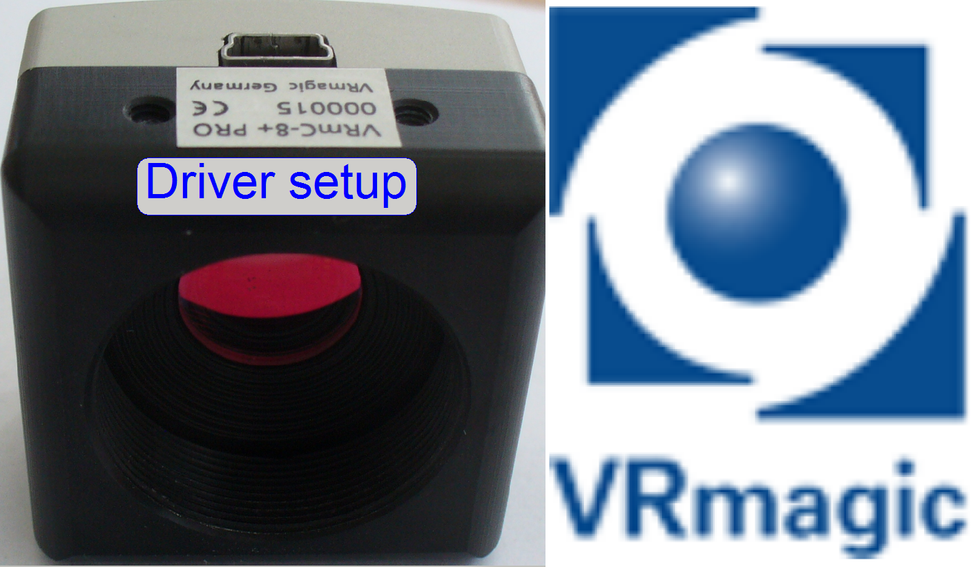 This camera makes a
preview of the slide before scanning (shown in the preview window of the scan
program), so parts of the slide and the tissue may be excluded from the scan
process.
This camera makes a
preview of the slide before scanning (shown in the preview window of the scan
program), so parts of the slide and the tissue may be excluded from the scan
process.
Connect the camera to an
USB2.0 port!
The camera uses
an USB 2.0 port, otherwise, if the transfer rate of 480Mb/s can not be reached
(USB1.1 or lower), the camera window will disappear automatically after some
seconds, without any notice!!
VRmagic USB
cameras are not compatible with USB 3.0 hosts. Always connect the camera to a
USB 2.0 host; otherwise it will not work properly.
Used in: ALL scanner types
Windows®
7 x 64bit
![]() Setup the driver for the
preview camera “VRMagic”
Setup the driver for the
preview camera “VRMagic”
Driver
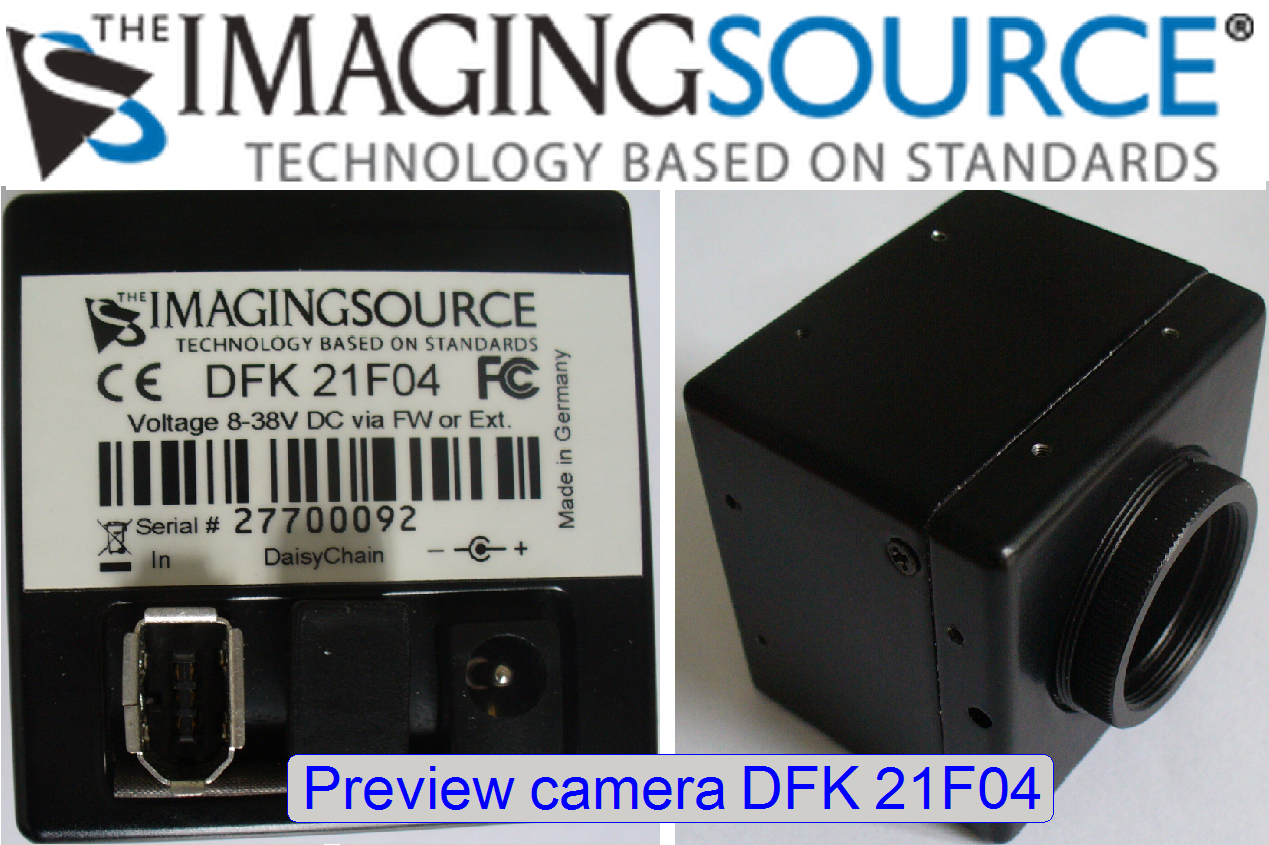
of the preview camera DFK 21F04
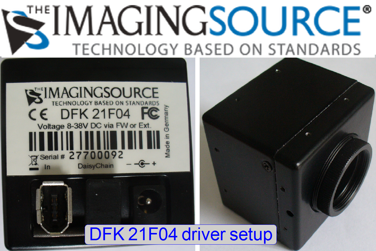 This camera
makes a preview of the slide before scanning (shown in the preview window of
the scan program), so parts of the slide and the tissue may be excluded from
the scan process.
This camera
makes a preview of the slide before scanning (shown in the preview window of
the scan program), so parts of the slide and the tissue may be excluded from
the scan process.
Connect the camera to a
FireWire port!
Used in: SCAN,
Windows®
7 x 64bit
![]() Setup the driver for
the preview camera “DFK 21F04”
Setup the driver for
the preview camera “DFK 21F04”
Used in: SCAN,
Windows®
XP x 32bit
![]() Setup the XP-driver for
the preview camera “DFK 21F04”
Setup the XP-driver for
the preview camera “DFK 21F04”
USB driver of the Pannoramic scanner
 Via the USB driver,
the software “SlideScanner.exe” and the service program “SlideScannerService.exe”
controls the mechanics, the optics and the illumination of the entire scanner.
Without this driver set up, communication between software and the Pannoramic
scanner is impossible.
Via the USB driver,
the software “SlideScanner.exe” and the service program “SlideScannerService.exe”
controls the mechanics, the optics and the illumination of the entire scanner.
Without this driver set up, communication between software and the Pannoramic
scanner is impossible.
Used in: ALL scanner types
Windows®
7 x 64bit
![]() Setup the USB driver for
the Pannoramic scanner
Setup the USB driver for
the Pannoramic scanner
Used in: SCAN,
Windows®
XP x 32bit
![]() Setup the XP-USB
driver for the Pannoramic scanner
Setup the XP-USB
driver for the Pannoramic scanner
Driver of the camera “Carl Zeiss AxioCam MRm R3”
 During
installation of the driver for the camera “Carl Zeiss AxioCam MRm R3” the “OHCI Host Controller (Legacy)” has to be selected,
otherwise, the camera will not working well (very slowly)!
During
installation of the driver for the camera “Carl Zeiss AxioCam MRm R3” the “OHCI Host Controller (Legacy)” has to be selected,
otherwise, the camera will not working well (very slowly)!
Used in: P250,
SCAN,
Windows®
7 x 64bit
![]() Setup the driver of
the camera AxioCam MRm REV.3
Setup the driver of
the camera AxioCam MRm REV.3
Used in: SCAN,
Windows®
XP x 32bit
![]() Setup the XP-driver of
the camera AxioCam MRm REV.3
Setup the XP-driver of
the camera AxioCam MRm REV.3
Driver of the camera “Stingray F-
“Marlin
F-
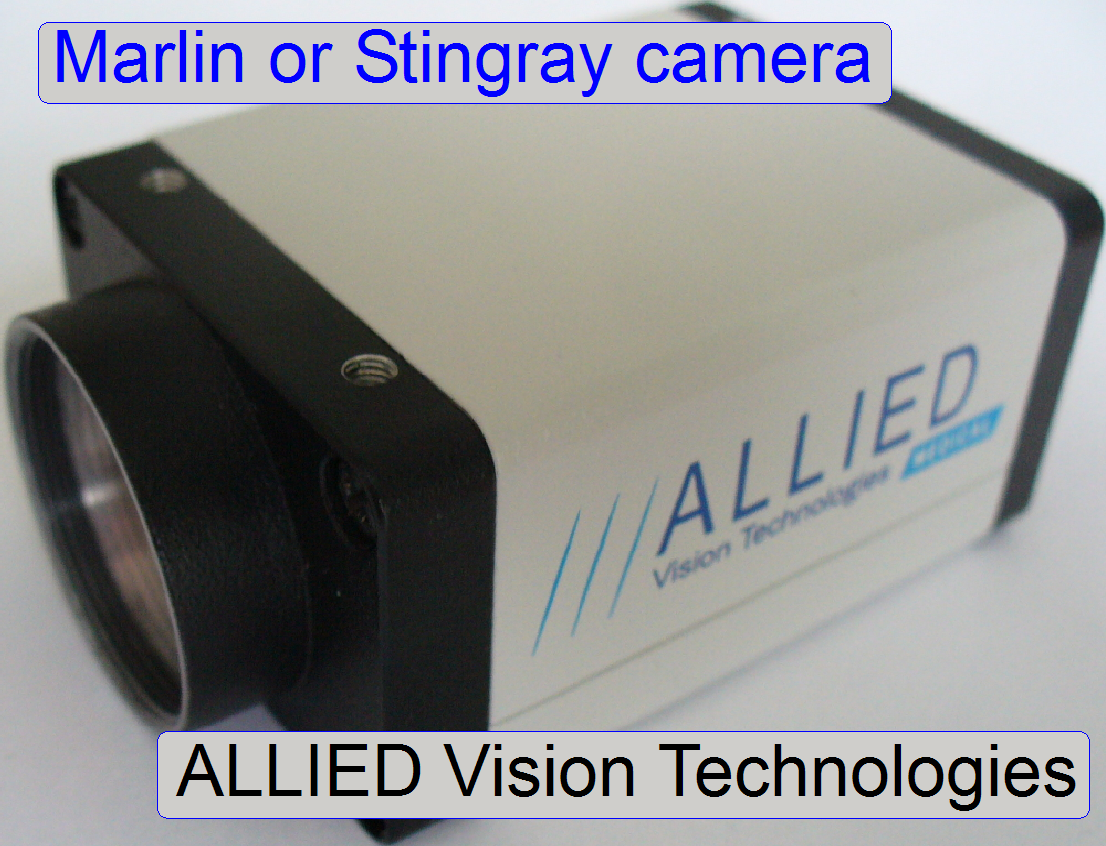 Both cameras are a
product of ALLIED Vision Technologies (AVT).
Both cameras are a
product of ALLIED Vision Technologies (AVT).
· If the driver “AVT
FirePackage” is installed for the appropriate software version, the cameras can
be connected likewise.
Used in: SCAN,
Windows®
7 x 64bit
Used in: SCAN,
Windows®
XP x 32bit
Setup
the scan program “Slide Scanner”
 The
scan program “Slide Scanner” creates the virtual slide by scanning the real
slide with a Pannoramic scanner.
The
scan program “Slide Scanner” creates the virtual slide by scanning the real
slide with a Pannoramic scanner.
Important
Before the scan program can
be set up, the Matrox Imaging Library version 9.0 (MIL 9.0) has to be installed
successful; otherwise, slide scanning will not work!
![]() above and “Setup_MIL_9”
above and “Setup_MIL_9”
Used in: ALL scanner types
Windows®
7 x 64bit
Before starting the scan
software “Slide Scanner”, the scanner USB driver
has to be installed;
![]() “USB driver of the Pannoramic
scanner”!
“USB driver of the Pannoramic
scanner”!
Important
Please install always only verified and tested versions of Windows® 7 x
64bit (related to Slide Scanner and Slide viewer);
![]() Setup
the operating system Windows® 7 x 64bit
Setup
the operating system Windows® 7 x 64bit
User’s
guide of your scanner
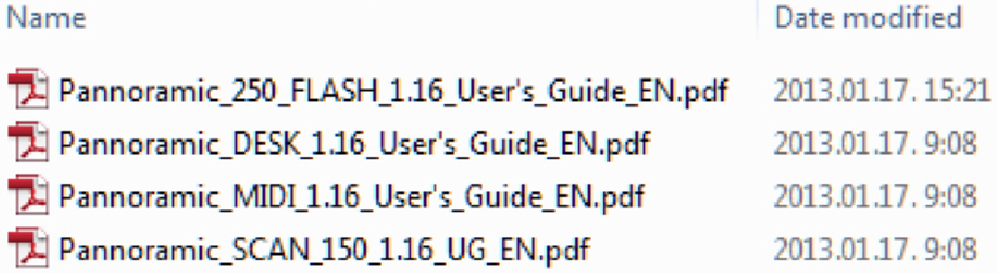
User guides, Pannoramic scanners
The most recent version is
found on the install DVD of the scan program version!
Setup the service program
“SlideScannerService”
 The service program
SlideScannerService.exe will be installed together
with the scan program “Slide Scanner”; see above:
The service program
SlideScannerService.exe will be installed together
with the scan program “Slide Scanner”; see above:
“Setup
the scan program “Slide Scanner””
Before starting the software
“Slide Scanner Service”, the scanner USB driver
has to be installed!
Copy the actual, valid
license file “MService.lic” into the folder:
C:\Program
Files\3DHISTECH\SlideScanner\
If the license file is not
valid, the program “SlideScannerService.exe” can be started but the options are
all inactive and can not be selected!
Start the program
“SlideScannerService.exe” by clicking the icon “SlideScannerService.exe” or
from its folder.
The
path is
C:\Program
Files\3DHISTECH\SlideScanner\SlideScannerService.exe
Please read
also the instructions of the service
program
Setup the viewer program “Slide Viewer”
 The
slide viewer makes the virtual slide(s), previously scanned by the program
“SlideScanner”, visible on the screen.
The
slide viewer makes the virtual slide(s), previously scanned by the program
“SlideScanner”, visible on the screen.
Important
If the viewer will be
uninstalled, all the licensed, previously installed viewer modules must be
installed again after the setup procedure of the viewer is finished!
Important
Please install always only verified and tested versions of Windows® 7 x
64bit (related to Slide Scanner and Slide viewer); see: Setup the operating system Windows® 7 x
64bit
Used in: ALL scanner types
Windows®
7 x 64bit
User’s guide
of the viewer

![]() Pannoramic_Viewer_ The most recent
version is found on the install DVD of the scan program version!
Pannoramic_Viewer_ The most recent
version is found on the install DVD of the scan program version!
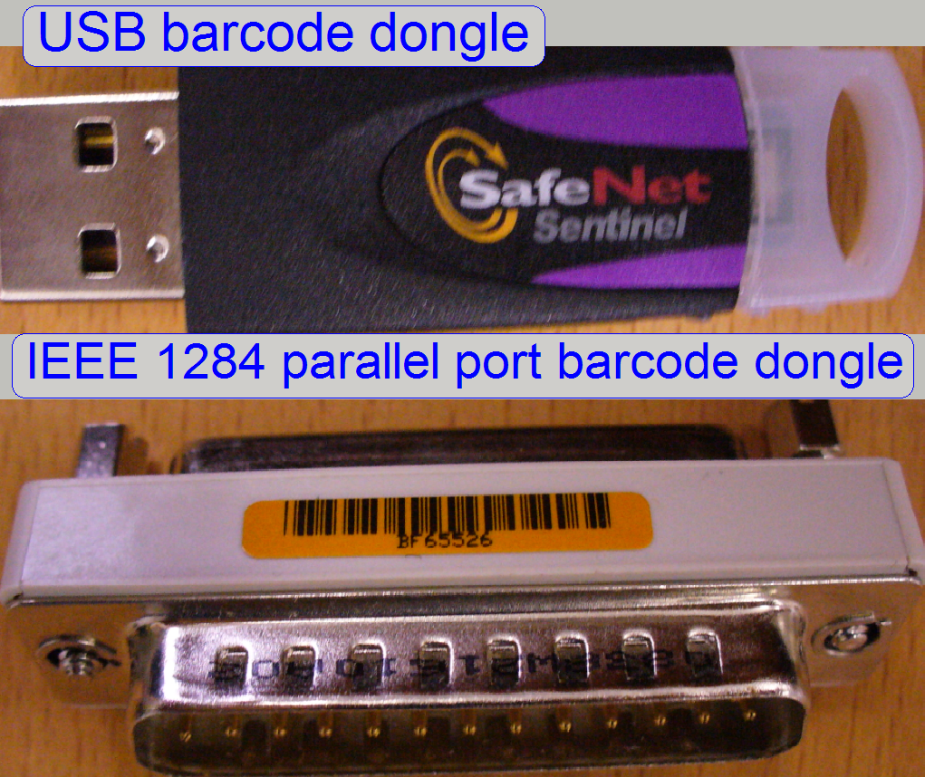
Barcode reading is license protected and requires a barcode dongle!
Used in: ALL scanner types
Windows®
7 x 64bit
![]() “Dongles”;
“Setup the Matrox Imaging
Library version 9.0 (MIL 9.0)”
“Dongles”;
“Setup the Matrox Imaging
Library version 9.0 (MIL 9.0)”
Used in: SCAN,
Windows®
XP x 32bit
![]() “Dongles”;
“Setup MIL 8.0”; “Setup MIL 9.0”
“Dongles”;
“Setup MIL 8.0”; “Setup MIL 9.0”
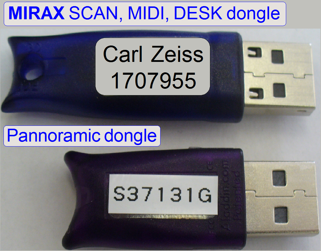
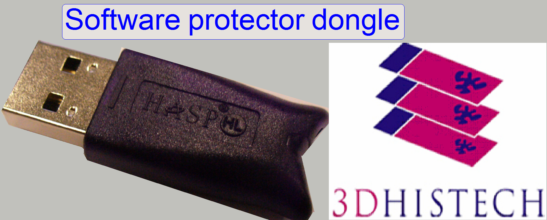 Special tasks of the program
“Slide Scanner” and modules of the program “Slide Viewer” are dongle protected!
Special tasks of the program
“Slide Scanner” and modules of the program “Slide Viewer” are dongle protected!
Used in: ALL scanner types
Windows®
7 x 64bit
![]() “Dongles for
Pannoramic scanners”
“Dongles for
Pannoramic scanners”
 Used
in: SCAN,
Used
in: SCAN,
Scanner
hardware conditions and cabling
If the entire
configuration (Pannoramic scanner and computer) is moved from place “A” to
place “B”, please use after movement the same ports and connections on the
computer rear as the configuration had during setup drivers and software. Only
this way a driver mismatch can be avoided.
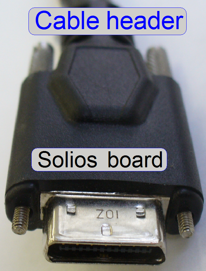
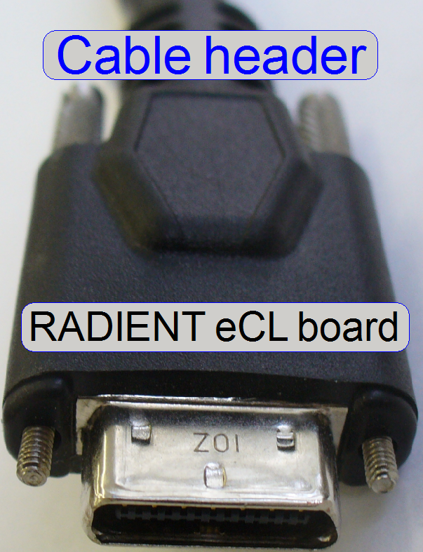
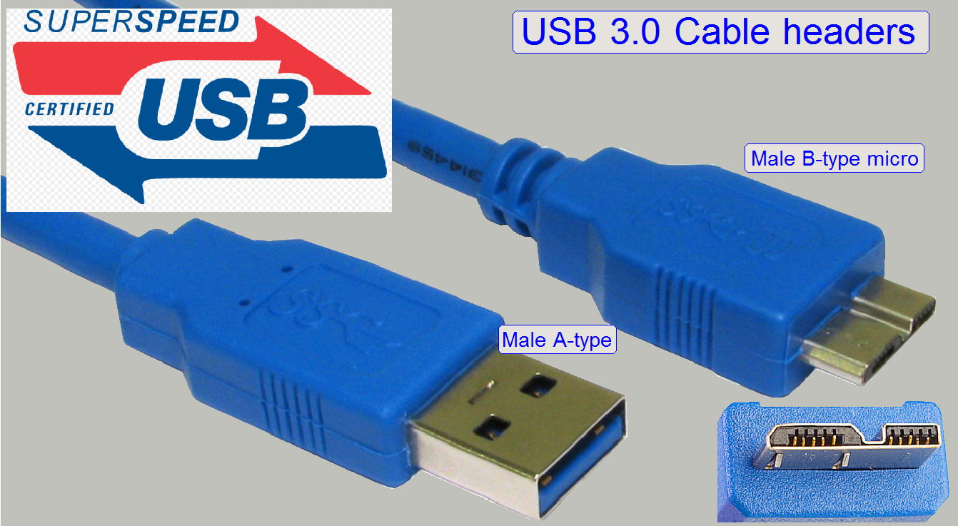
 To achieve high
data transfer rates and save connectivity of the cable headers, please use
always cables of a high quality.
To achieve high
data transfer rates and save connectivity of the cable headers, please use
always cables of a high quality.
Exchange the cable if it is damaged in any way.
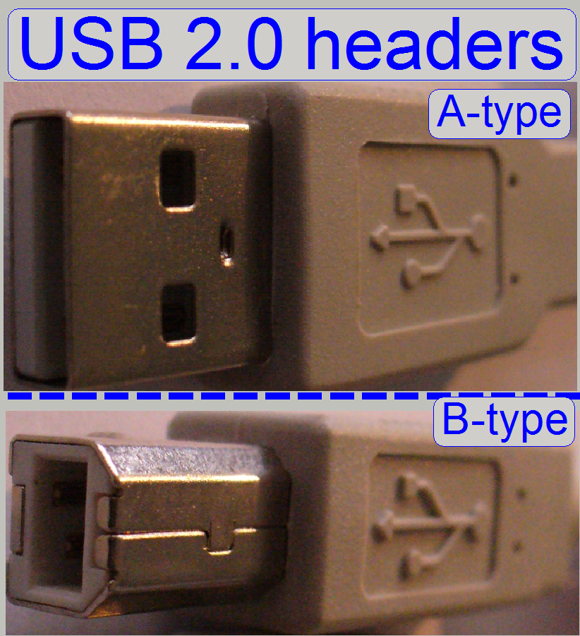
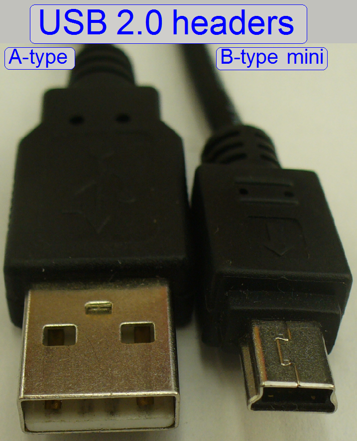
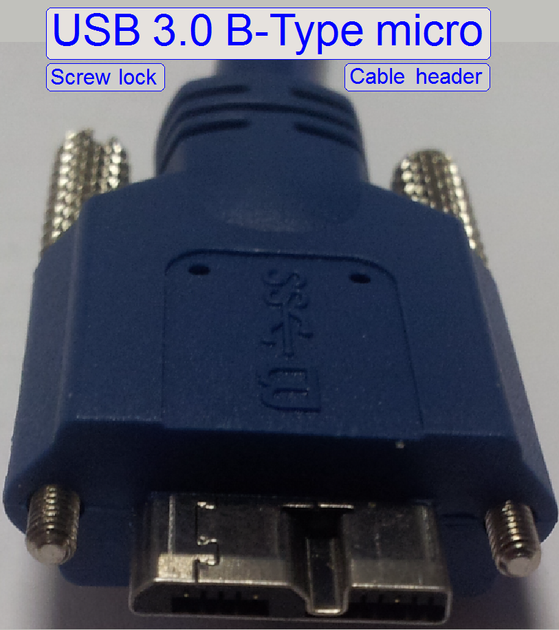
The USB 2.0 Hi-Speed interface is able to transfer data in a rate of 480
Mbit/s maximal. If the conditions for this transfer rate are not met, the speed
is automatically reduced to a transfer rate of 12Mbit/s.
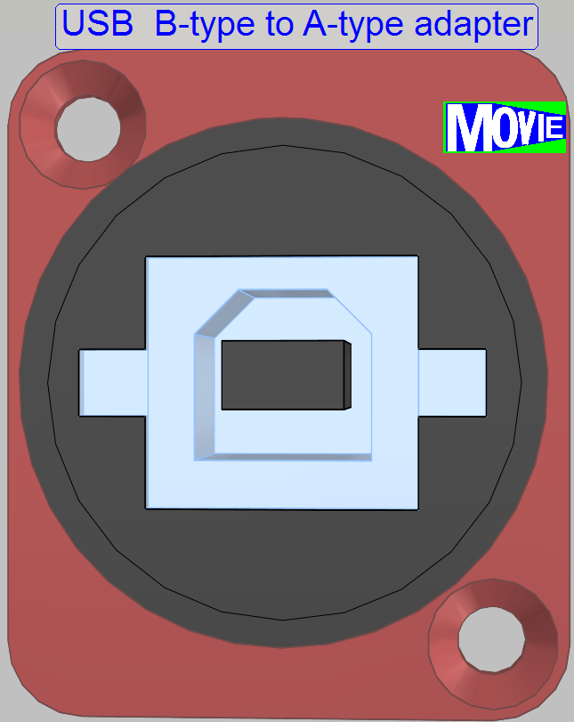
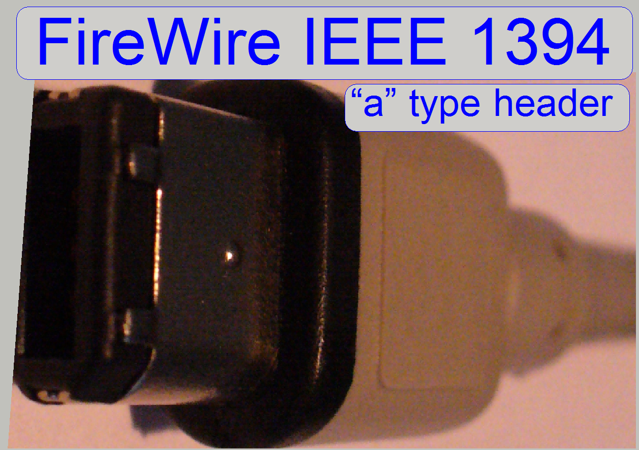
The “A” type header is always connected to the host port (computer), the
“B” type header is connected to the peripheral (Pannoramic scanner).
![]() “USB driver of the Pannoramic scanner”
“USB driver of the Pannoramic scanner”
![]() USB interface Wikipedia
USB interface Wikipedia
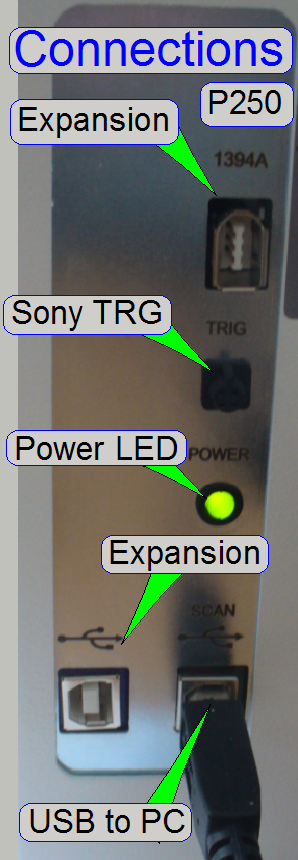
USB to PC
 Via this port the
control of the scanner is realized; the Pannoramic scanner gets commands from the
software for the stepper motors and illuminations; the status information
(state of sensors, stepper motor position reached) is returned to the software.
Via this port the
control of the scanner is realized; the Pannoramic scanner gets commands from the
software for the stepper motors and illuminations; the status information
(state of sensors, stepper motor position reached) is returned to the software.
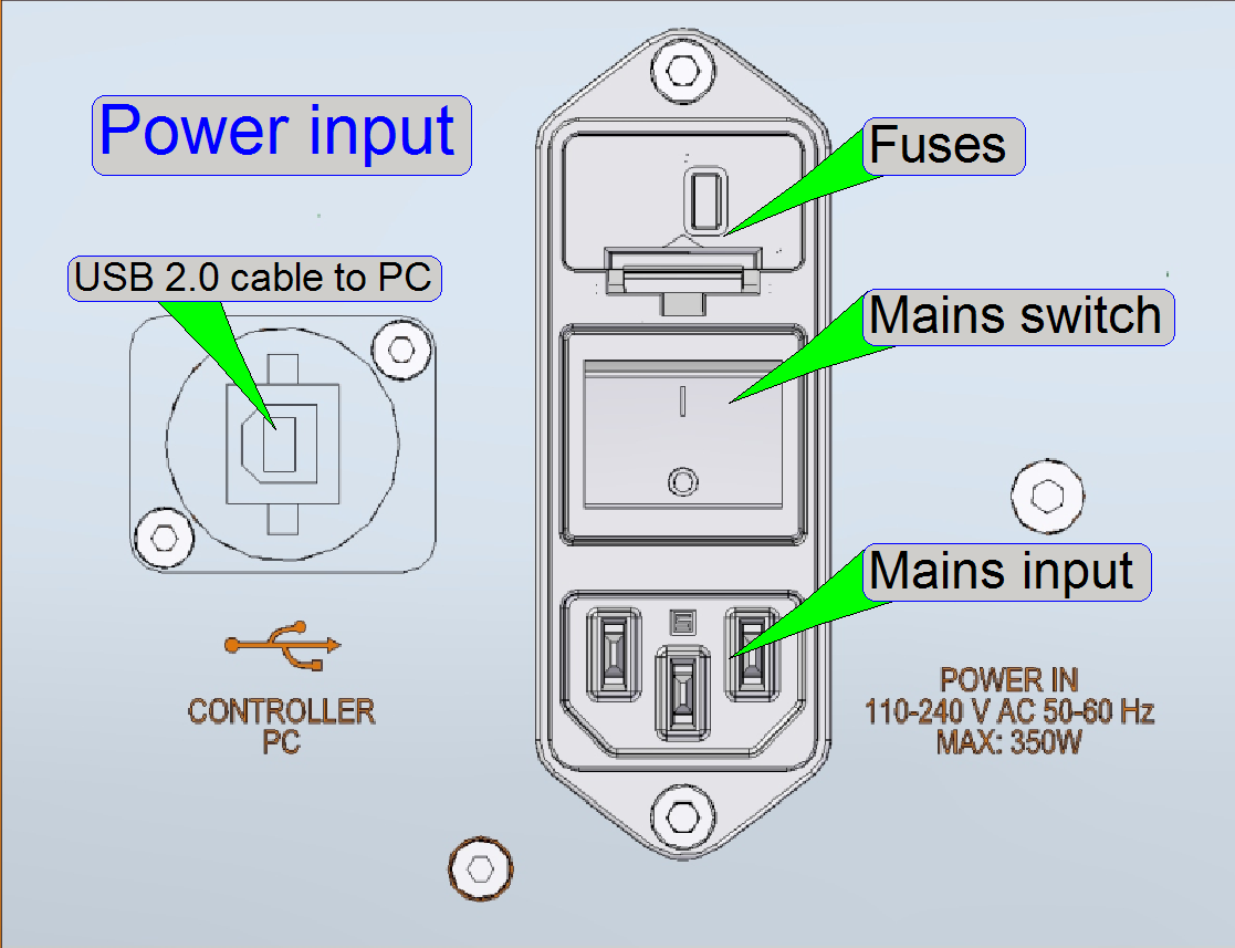
Power
Connect the appropriate power
cable! See also: Power input
The input voltage may be in the range from 100V~ to 240V~.
See also: Power supply tdk-Lambda
Other connections
Please refer to the chapters
Lumencor SPECTRA Light Engine®
Preview camera VRmagic
Connections of P250
USB to PC
 Via this port the control of the scanner is realized; the Pannoramic
scanner gets commands from the software for the stepper motors, illuminations
and the DC-motors; the status information (state of sensors, stepper motor
position reached) is returned to the software.
Via this port the control of the scanner is realized; the Pannoramic
scanner gets commands from the software for the stepper motors, illuminations
and the DC-motors; the status information (state of sensors, stepper motor
position reached) is returned to the software.
Expansion
These connectors are
momentarily not in use, they are reserved for further expansions.
Power
Connect the appropriate power
cable! See also: Power input
The input voltage may be in the range from 100V~ to 240V~.
Other connections
Please refer to the chapters
Preview camera VRmagic
Lumencor SPECTRA Light Engine®
Power
LED
The power LED is lighting if
the power is supplied to the Pannoramic scanner (the power cable is connected;
the power supply and the emergency switch are switched on).
If the power LED is not lighting
Check the mains power in the connector outlet.
Check the power cable and its right
connection.
Check the mains power switch state on the
rear.
Check the emergency switch state.
Check the output voltages of the power supply.
If the power LED is flashing
If there is a shortcut inside
the scanner, the power supply is switched off by overload; every 200 ms the
power supply will switch on it self and tries to supply the output voltages.
This behavior makes slightly flashing the power LED; the fans may rotate.
Switch off the mains power of the power
supply and measure with the ohmmeter the resistance between the positive and the negative
pole of the output voltages 24V, 12V and 5V of the power supply “tdk Lambda”. (Do not measure
the +pole in relation to ground, because the power outputs are ground
independent!)
Remove the power output connectors of the “Power distribution and switch board” and switch on
the power supply again.
Remove the Power input connector of the “Power distribution and switch
board” and switch on the power supply again.
Remove the power output connections of +24V of the power supply “tdk Lambda” and switch on
the power supply again.
Remove the power output connections of +12V of the power supply “tdk
Lambda” and switch on the power supply again.
Remove the power output connections of +5V of the power supply “tdk
Lambda” and switch on the power supply again.
If the shortcut disappeared, measure
the resistance of the disconnected paths / wires with the ohmmeter against the
negative pole of the appropriate output voltage or reconnect the appropriate
connections singly, separately to find the faulty path.
Sony TRG
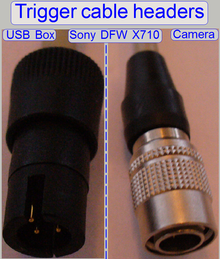 If the Sony camera DFW-X710 is used, the trigger
cable, delivered with the Sony camera is connected on this connector. If the
trigger cable is not connected (or damaged) the camera will not work.
If the Sony camera DFW-X710 is used, the trigger
cable, delivered with the Sony camera is connected on this connector. If the
trigger cable is not connected (or damaged) the camera will not work.
Further cabling and connections can be found in the appropriate chapter
of the unit.
![]() “Preview camera
VRmagic”; “Camera CIS-
VCC-F52U25CL”, “Camera PCO-edge” and “Lumencor SPECTRA light engine”
“Preview camera
VRmagic”; “Camera CIS-
VCC-F52U25CL”, “Camera PCO-edge” and “Lumencor SPECTRA light engine”
Pannoramic SCAN,
Scanners since 2006
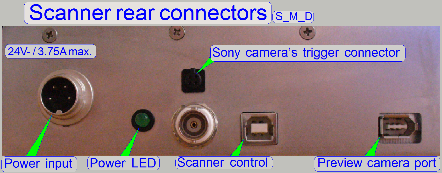
These scanners have the same
USB controller box. In the Pannoramic MIDI this box is rotated by 90 degrees,
but the connector arrangement is the same. If earlier, before 2006 developed
Pannoramic SCAN scanners are upgraded, the entire preview part of the scanner
is modified and so the USB controller box contains the FireWire connector for
the preview camera DFK 21F04.
Power input
On this connector the external power supply is connected.
Power LED
The power led is lighting if
the power is supplied to the Pannoramic scanner (the power supply is connected
and switched on).
Sony trigger connector
If the
Sony camera DFW-X710 is used, the trigger cable, delivered with the Sony camera
is connected on this connector. If the trigger cable is not connected (or
damaged) the camera will not work.
See also “Trigger connector”
USB control port
Via this port the Pannoramic
scanner gets commands from the software for the stepper motors, illuminations
and the DC-motors; the status information (state of sensors, stepper motor
position reached) is returned to the software.
Preview camera port
·
 If the scanner uses the
preview camera VRmC-8+ PRO (since SW version 1.16), the FireWire connector is
replaced by an USB 2.0 port “B”- type connector.
If the scanner uses the
preview camera VRmC-8+ PRO (since SW version 1.16), the FireWire connector is
replaced by an USB 2.0 port “B”- type connector.
USB Controller
Modifications since summer 20116
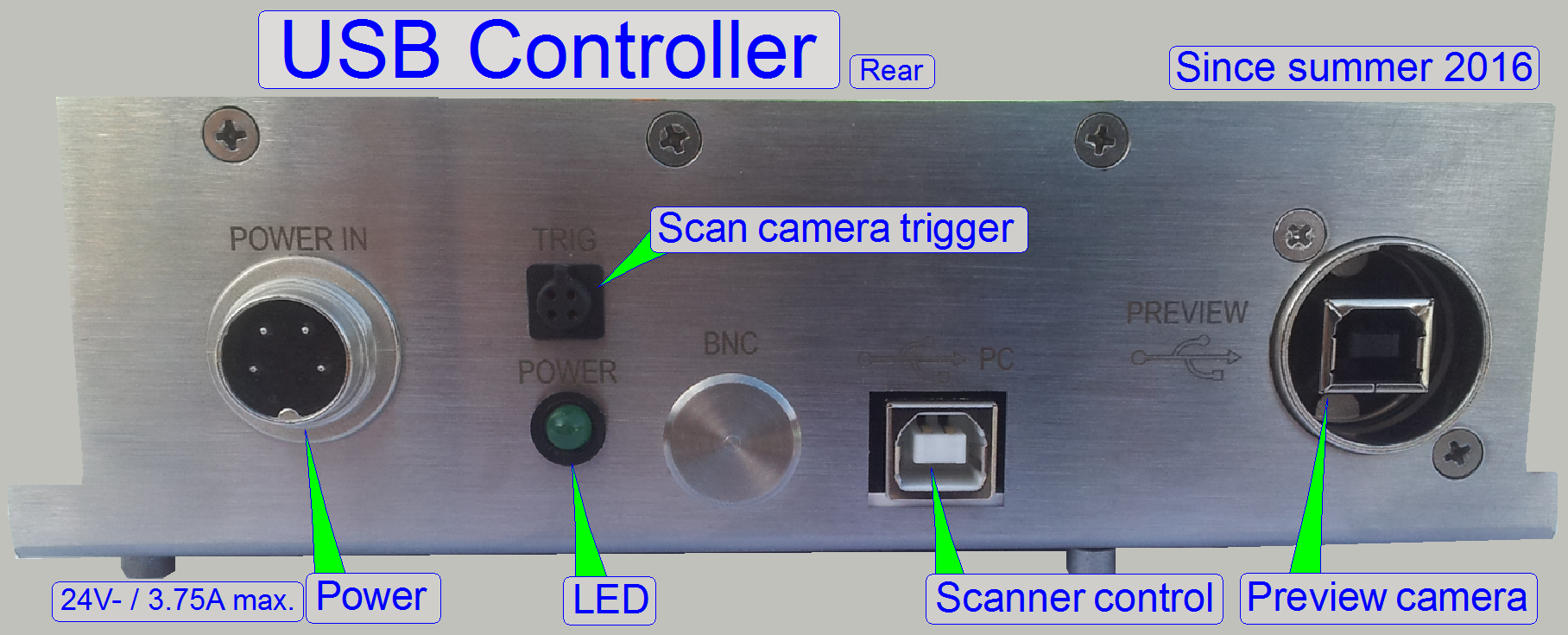 The BNC connector
is left out and the trigger cable connector works for the camera
“Grasshopper3”.
The BNC connector
is left out and the trigger cable connector works for the camera
“Grasshopper3”.
The connector for the preview camera is always a USB 2.0 Receptacle.
|
USB controller labels; summer 2016 |
|||
|
Unit |
SCAN |
|
DESK |
|
RGB BF
illumination |
LBF-1 |
LBG-1 |
LBI-1 |
|
X-Motor |
STF-1 |
STG-1 |
STI-1 |
|
Y-Motor |
STF-2 |
STG-2 |
STI-2 |
|
Z-Motor |
STF-3 |
STG-3 |
STI-3 |
|
DC control |
DCF-1 |
DCG-1 |
DCI-1 |
|
Objective
changer |
DOF-1 |
DOG-1 |
---- |
|
Preview
illumination |
BGF-1 |
BGG-1 |
BGI-1 |
|
RGB BF trigger |
LTF-1 |
LTG-1 |
LTI-1 |
|
Tray Loader
motor |
---- |
STG-5 |
---- |
|
Slide loader
motor |
---- |
STG-6 |
---- |
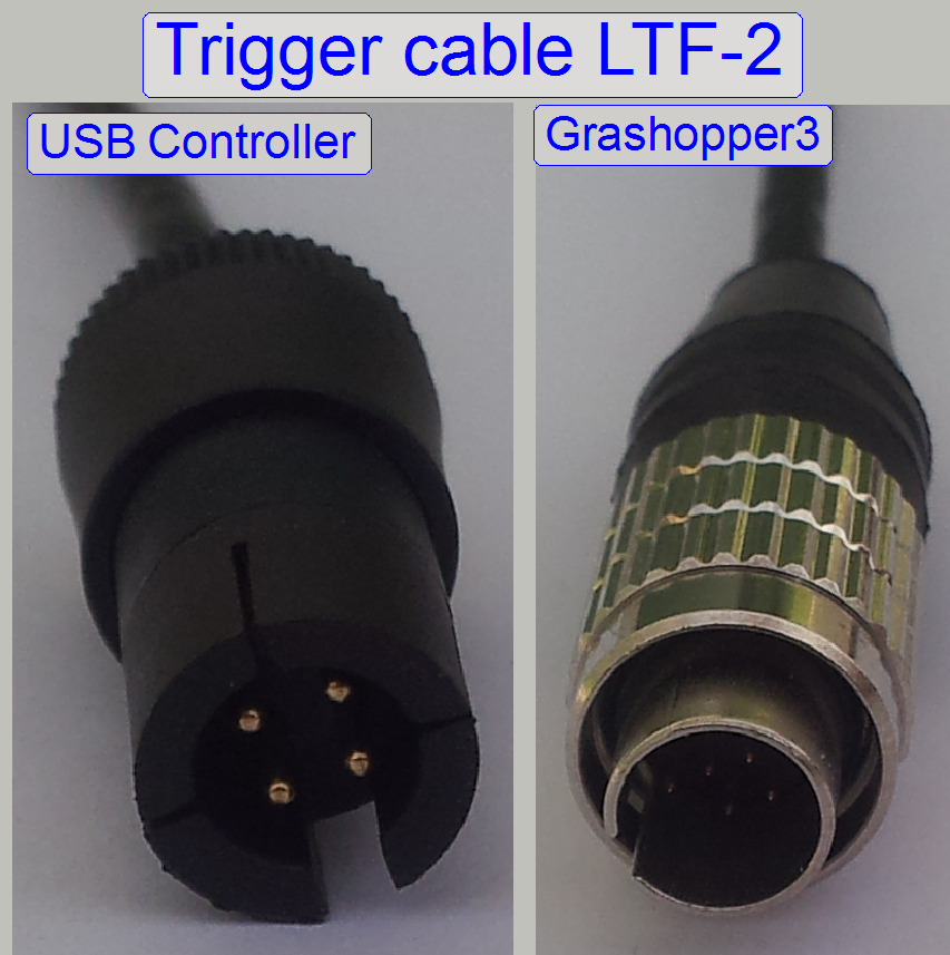
The trigger cable LTF-2 is used during only BF scan procedures (DESK;
MIDI_BF, SCAN_BF) with the camera “Grasshopper3”.
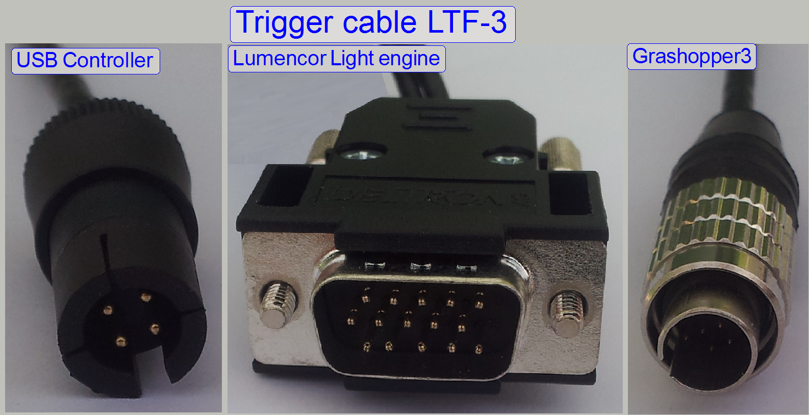
The trigger cable LTF-3 is used during BF and FL scan sessions
procedures with the camera “Grasshopper3” (SCAN,
The preview camera type is defined in the file
“MicroscopeConfiguration.ini” in the section [Microscope] and the parameter
“PreviewCameraType=”; regardless of the software version.
Pannoramic
250
[Microscope]
SerialNumber=
MicroscopeType=3DMic9
ScanCameraType=
PreviewCameraType=CVrmc_m8_pPro
BarcodeReaderType=PreviewCamera
Remark
The preview camera type, depending on the scanner type,
may be:
PreviewCameraType=CVrmc_m8_pPro; 3DMic9, since
the SW version 1.16: 3DMic8; 3DMic7; 3DMic5
also.
PreviewCameraType=DFK21F04; 3DMic6; 3DMic8; 3DMic7; 3DMic5; until
the software version 1.14.
Used in: PCON, P250, since SW version
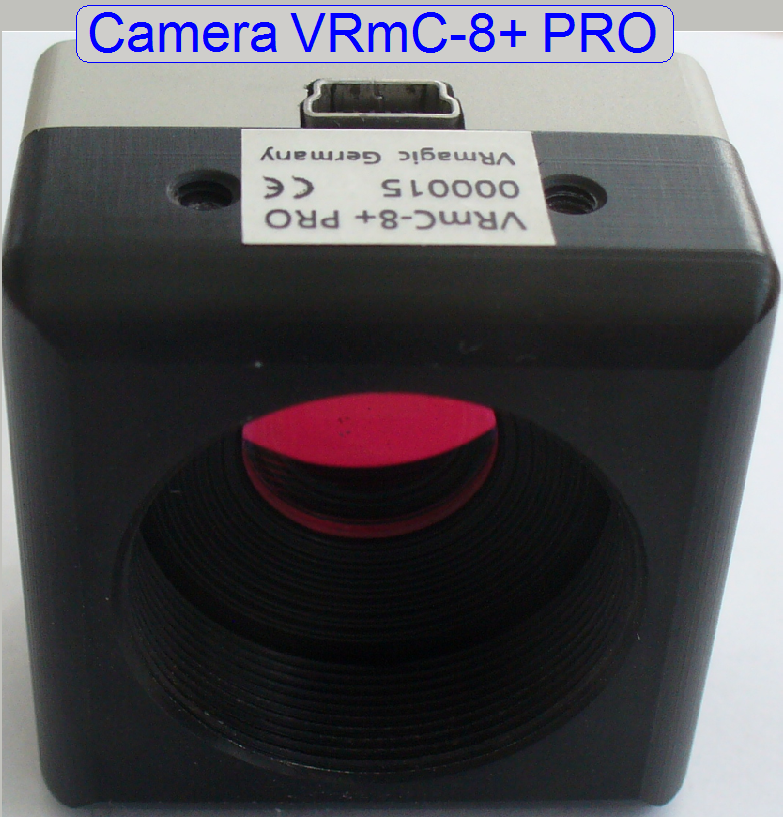
 The camera VRmC-8+ PRO
uses a CMOS sensor with Rolling shutter and has
an image size of 2056 x 1544 pixels.
The camera VRmC-8+ PRO
uses a CMOS sensor with Rolling shutter and has
an image size of 2056 x 1544 pixels.
Technical
data
High-speed USB 2.0 (EHCI)
Power supply via USB Standard
Mini USB-B connector
Pixel array size 2056(H) x 1544(V) used: 2048(H) x 1536(V)
Active pixel size 3.2µm x 3.2µm
Rolling shutter CMOS
Optical format 1/2”
The camera
VRmC-8+ PRO is used as preview camera in all
scanner types; the made images are assembled to a preview.
The image,
produced of the barcode area is used by the barcode reading software to analyze
the barcode (if installed and licensed).
Since the
software version 1.16, the preview camera VRmC-8+ PRO may also be used in the
scanners PSCAN, PMIDI and PDESK.
Further
information about features, precautions and other technical data can be found
in the file “VRmC-8_PRO__color_.pdf”
Important
The camera uses
an USB 2.0 high-speed port, otherwise, if the transfer rate of 480Mb/s can not
be reached, the camera connection will be lost automatically after some
seconds, without any notice!
If such behavior
occurs, please try with another USB 2.0 port and remove the driver (if
required), then setup the driver again.
Please do not
allow the option “USB XHCI” (allows the use of USB 3.0 speed) in the BIOS
setup!
Please set the
USB 2.0 port always to the appropriate protocol “USB EHCI” in the BIOS setup
also, otherwise the VRmagic will not be recognized or the host connection may
be lost after some seconds!
Powering and cabling
 The camera VRmagic
is connected to the appropriate USB 2.0 port of the computer; so the powering
is realized by the USB interface.
The camera VRmagic
is connected to the appropriate USB 2.0 port of the computer; so the powering
is realized by the USB interface.
On the camera side an USB 2.0 mini-B type cable header is connected; the
cable length is 3m nominal.
VRmagic USB
cameras are not compatible with USB 3.0 hosts. Always connect the camera to a
USB 2.0 host; otherwise it will not work properly.
Driver
setup
Used in: P250: SW version 1.15 and higher
S_M_D: SW version 1.16 and higher
Setup the driver for the
preview camera “VRMagic”
Setup the program “CamLab”
Configure
the camera
In the file
“MicroscopeConfiguration.ini” Section [Microscope] the preview camera is
defined as follows
Preview Camera
PreviewCameraType=CVrmc_m8_pPro; S_M_D, P250, PCON, Preview camera for
delivered scanners since SW version 1.15
PreviewCameraSerialNumber=000XXX; SCS; because there are several VRM-magic
cameras, the serial number is used to distinguish the cameras.
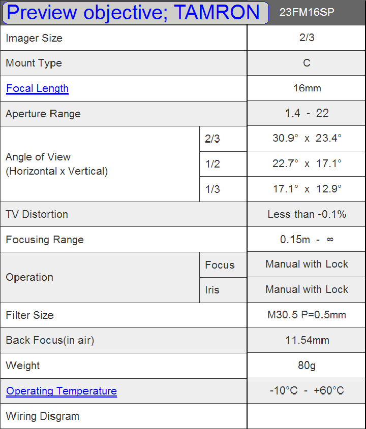
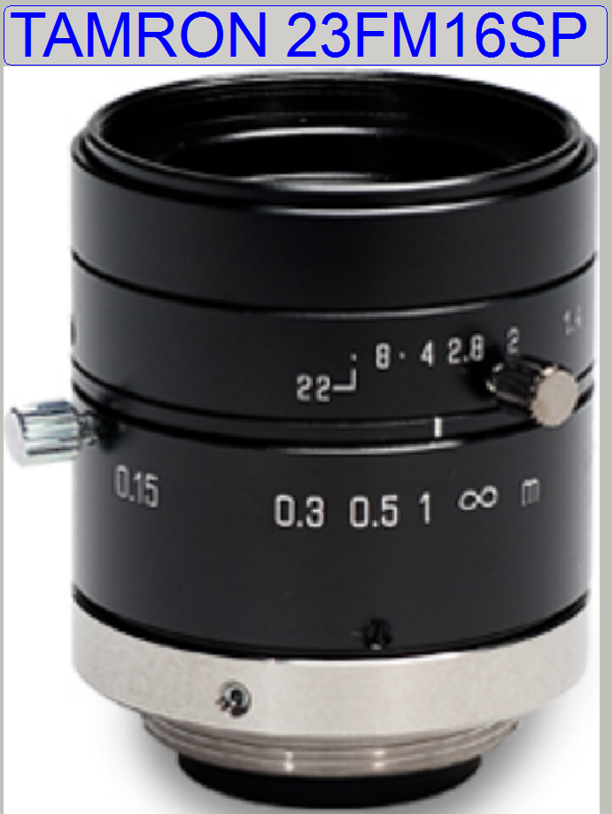 Preview objective; TAMRON 23FM16SP
High
resolution lens for sensor size up to 2/3"-CCD
Focal length
Aperture F1,4
MOD
Filter thread M30,5 x 0,5
Camera mount C-Mount
Aperture und focus with
locking screws
Modifications since summer 20116
VRMC-8+/C
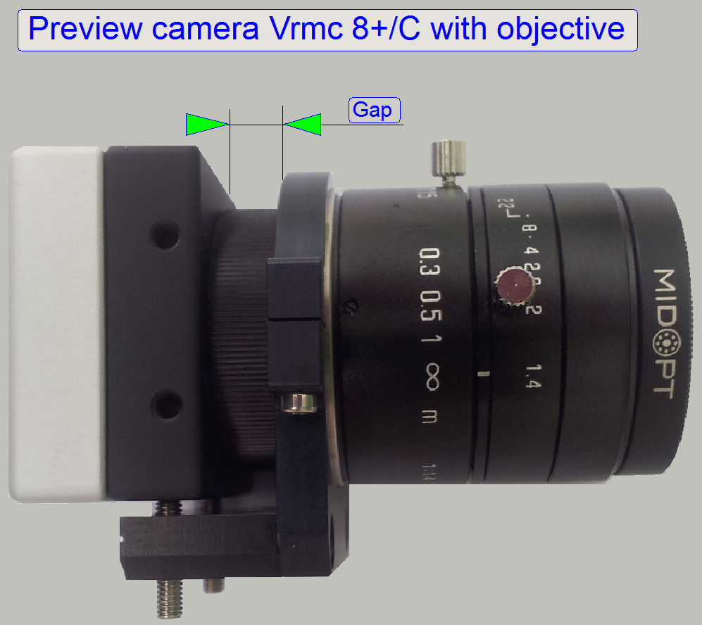
Since autumn of
·
The production of the camera VRmC-8+
PRO was discontinued in 2016.
·
Mount the camera holder next to the knurled distance
ring as shown.
Adjust the real focus position with the focusing part of the objective
during the preview calibration procedure.
For camera and objective values, cabling, driver setup and others,
please refer to the camera VRmC-8+ PRO, above.
|
Features; VRmC-8+/C |
|
|
Parameter |
Value |
|
Resolution (H x V) |
2048 x 1536 |
|
Pixel Size [µm] |
3.2x3.2 |
|
Megapixels |
3.0 MP |
|
Color |
RGB Bayer |
|
Sensor Name |
Aptina MT9T031 |
|
Sensor Type |
CMOS |
|
Readout Method |
Rolling shutter |
|
Optical Format |
1/2" (4:3) |
|
Frame Rate |
13 FPS |
|
Lens Mount |
C-mount |
|
ADC |
8-bit and 10-bit |
|
Interface |
USB 2.0 |

Flea 3
Used in: P1000
Preview camera for slide viewing and barcode capturing
Type: FL3-U3-120S3C-C
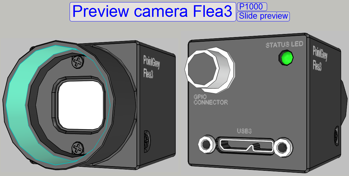 Manufacturer: Pointgrey
|
Features; FL3-U3-120S3C-C |
|
|
Parameter |
Value |
|
Resolution (H x V) |
4000 x 3000 |
|
Pixel Size [µm] |
1.55x1.55 |
|
Megapixels |
12.0 MP |
|
Chroma |
Color |
|
Sensor Name |
Sony IMX172 |
|
Sensor Type |
CMOS |
|
Readout Method |
Rolling shutter |
|
Optical Format |
1/2.3" |
|
Frame Rate |
15 FPS |
|
Lens Mount |
C-mount |
|
ADC |
12-bit |
|
Interface |
USB 3.0 |
![]() Flea3;
Flea3-IMX172;
camera catalog
(stored)
Flea3;
Flea3-IMX172;
camera catalog
(stored)
Used in: SCAN,
This camera is used in
current delivered Pannoramic scanners since the year 2006 and is implemented
into the upgrades of earlier scanners also. The camera delivers the preview of
the slide and the content of the barcode area for barcode analyzing and
decoding.
FireWire
color camera
Image sensor type: Sony ICX098BQ
1/4" CCD, progressive scan
Resolution: 640 x 480 pixels
Pixel dimension: 5.6μm (H) × 5.6μm (V)
Speed: 30fps max.
Interface: IEEE 1394a
Configure
the camera
In the file
“MicroscopeConfiguration.ini” Section [Microscope]
the preview camera is defined as follows
Preview Camera
PreviewCameraType=DFK21F04; S_M_D type scanners; Preview camera for
delivered scanners until SW version 1.14
The camera is defined and can be used in higher software versions also;
the parameter is independent of the software version.
![]() “Section [Microscope]”, “Spectral sensitivity and color formats”, Image sensor “Sony ICX098BQ”
and “Preview_S_M_D”
“Section [Microscope]”, “Spectral sensitivity and color formats”, Image sensor “Sony ICX098BQ”
and “Preview_S_M_D”
· The production of
the camera was discontinued in spring of the year 2012; so newer versions of
SCAN,
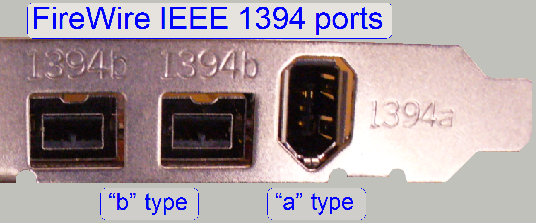
Requirements
FireWire IEEE 1394 “a” type port on the computer
 FireWire IEEE 1394 “a” to “a” type cable
The driver program
„drvInstaller.exe”.
 The FireWire interface is able to transfer data in
a rate of 400Mbit/s maximal.
The FireWire interface is able to transfer data in
a rate of 400Mbit/s maximal.
The cable may be equipped with:
“a” type and “a” type header
“a” type and “b” type header
“b” type and “b” type header
![]() FireWire interface Wikipedia
FireWire interface Wikipedia
The preview camera is connected to the computer with a FireWire “a” to “a” type header cable and to the rear of the
Pannoramic scanner.
![]() “How to
check the preview camera”; example for MIDI
“How to
check the preview camera”; example for MIDI
Check or set the following entries in the file
“MicroscopeConfiguration.ini”:
[Microscope]
PreviewCameraType=DFK21F04
[PreviewCamera]; until SW version
1.14; the parameter values are for information only!
FramePerSec=15
Brightness=402
Contrast=0
Saturation=128
Sharpness=99
ColorEnabled=0
BacklightCompensation=0
Gamma=1
Gain=0
WhiteBallance_U=70
Shutter=-9
FlipVertical=TRUE
FlipHorizontal=FALSE
AutoCalibrate=FALSE
MaxImageBrightness=190
MaxImageBrightnessIntegral=0.99
ImageBrightnessLowerLimitRate=0.85
ImageBrightnessUpperLimitRate=1.05
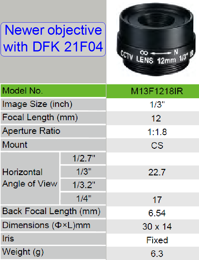
Preview
objective type used together with the preview camera “DFK 21F04” since spring
2012.
Driver
install
Since the
software version 1.16 Setup the Windows®
7x64bit driver for “DFK 21F04”
Until the
software version 1.14 Setup the Windows® XP
driver for “DFK 21F04”
For other preview cameras, used in earlier developed
scanners before the year 2006, please refer to “Early_preview_cameras”
For not shown chapters,
please use the links