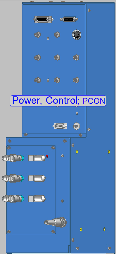
Power, control;
PCON
For technicians and partly for sales managers!
 The scanner Pannoramic
Confocal got some modifications concerning the power supply and the electronics
also, these modifications are required because in practice a scanner unit,
based on the modular
The scanner Pannoramic
Confocal got some modifications concerning the power supply and the electronics
also, these modifications are required because in practice a scanner unit,
based on the modular
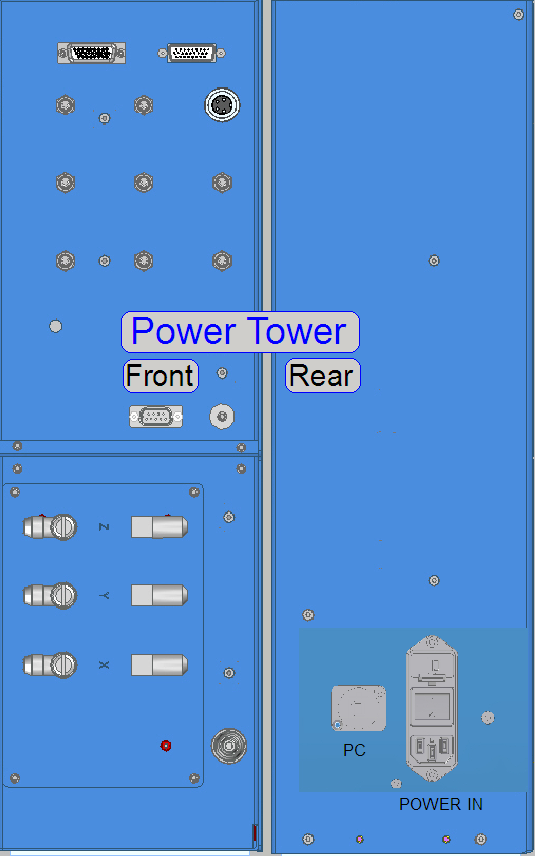
� The entire power
unit got a separate housing also and is arranged in a tower; the so-called
�Power tower�
� The internal
construction and used components are derived from the scanner P250.
� Software related settings
and checks are based on the software version 1.19
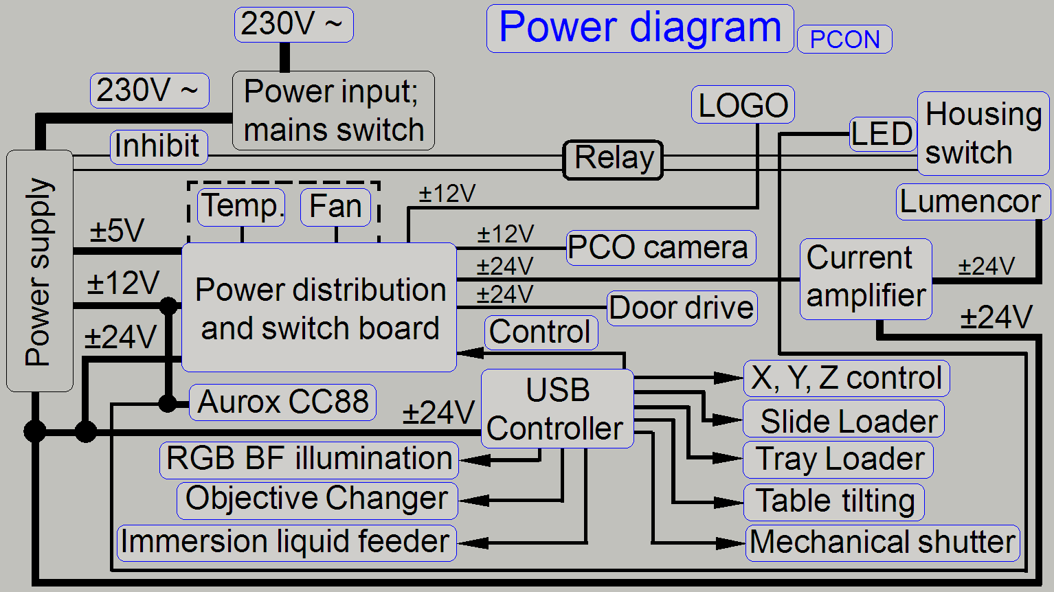
The power supply and control electronics consists of the following
components and units:
- General
- Power input
connector and main switch
- Power supply
- Housing (standby) Switch
- Power
distribution and switch board
- USB Controller with EEPROM
- Mechanical shutter
- Immersion liquid
feeder
- RGB BF scan illumination
- X-Y-Z-motor control
- Stepper motors
with control electronics mounted
- Stepper
motors without control electronics mounted
- Temperature
and fan control
- Parts; Components
- Cabling;
summary
See:��� �Power tower slide show�
Important remark
�����������
� After
maintenance
or service and performed tests of the scanner are 100 % finished, protective
ground connections and other safety regulations related to hazardous voltages,
accessible conductive parts and dangerous to life parts have to be checked
(again).
The
main modifications in relation to the modular
 The PCON
power supply is realized as an internal OEM power supply
module.
The PCON
power supply is realized as an internal OEM power supply
module.- The power
distribution for momentarily unused units or all units in emergency
situations (overheating) can be
switched off by the PIC controller firmware.
- The focus
unit stepper motor was changed to a motor with higher resolution (6400
steps / revolution).
- Control of
the objective changer
- Brightfield RGB
illumination control
- The mechanical shutter is
controlled via a stepper motor
- The X-Y- Z-
stepper motors does not contain control electronics; the control
electronics for these motors was separated
- Independent temperature
sensing and regulation by the control of the fan�s speed.
- Further sensors are
implemented.
- A darkfield preview
illumination was implemented.
- Power supply
and control of the Lumencor
SPECTRA light engine.
- Power supply of the
spinning disk system Aurox CC88.
- Immersion liquid
feeder powering and control.
- Tilting table
motor control.
- Aventos servo unit
to drive the motorized front door
- Illuminated logo.
Configure electronics components
Since the software version 1.15
the units of the scanner are configured in the file
�MicroscopeConfiguration.ini�, section [Microscope].
The actual version of the electronics components in the scanner PCON is
defined as follows:
[Microscope]
SerialNumber=xxxxxx
MicroscopeType=3DMic10
PreviewCameraType=CVrmc_m8_pPro
BarcodeReaderType=PreviewCamera
LoaderType=SL_1Mag_12Slide_Sensor_Horizontal
CameraChangerType=CC_None
ReflectorTurretType=RT_None
BrightfieldLightSourceType=RGBLedLight
ObjectiveChangerType=OC_2Pos
ObjectGuideXYZType=OGXYZ_FLASH4
FlashUnitType=FlashUnit_Type2;��������������������������������������������������� see
also: X-,X-,Z-controller
NDFilterType=ND_None
PreviewLightType=PreviewLightUnitType_Type2
ConfocalUnitType=ConfocalUnitType_Aurox
WaterFeederType=WaterFeeder_Type1;��������������������������������������� Immersion
liquid feeder, WF_None (if not present)
PowerSwitchBoardType=PowerSwitchBoard_Type1�������������������������� see
also: Power
distribution and switch board
�
Remark
To enable the
X-,Y-,Z-controller:
FlashUnitType=FlashUnit_Type2
Actually, the most recent
�Type2� is used.
To disable the X-,Y-,Z-,controller:
FlashUnitType=FlashUnit_None
To enable the switch board:
PowerSwitchBoardType=PowerSwitchBoard_Type1
Actually, the most recent
�Type1� is used.
To disable the switch board:
PowerSwitchBoardType=PowerSwitchBoard_None
 The main
components of the power supply and control electronics are arranged in a �Power
tower�.
The main
components of the power supply and control electronics are arranged in a �Power
tower�.
In the bottom part a fan with particle filter is implemented, so the
power supply and other electronics components reach cooling.
A temperature sensor is implemented to avoid probable overheating.
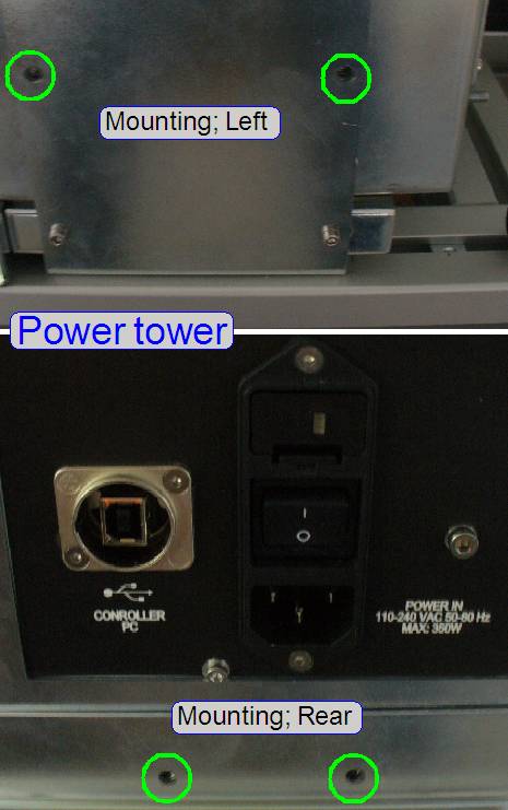
� The entire power
tower is mounted by 4 bolts to the truss of the PCON.
More detailed information about the internal construction can be found
in the �Power tower gallery�
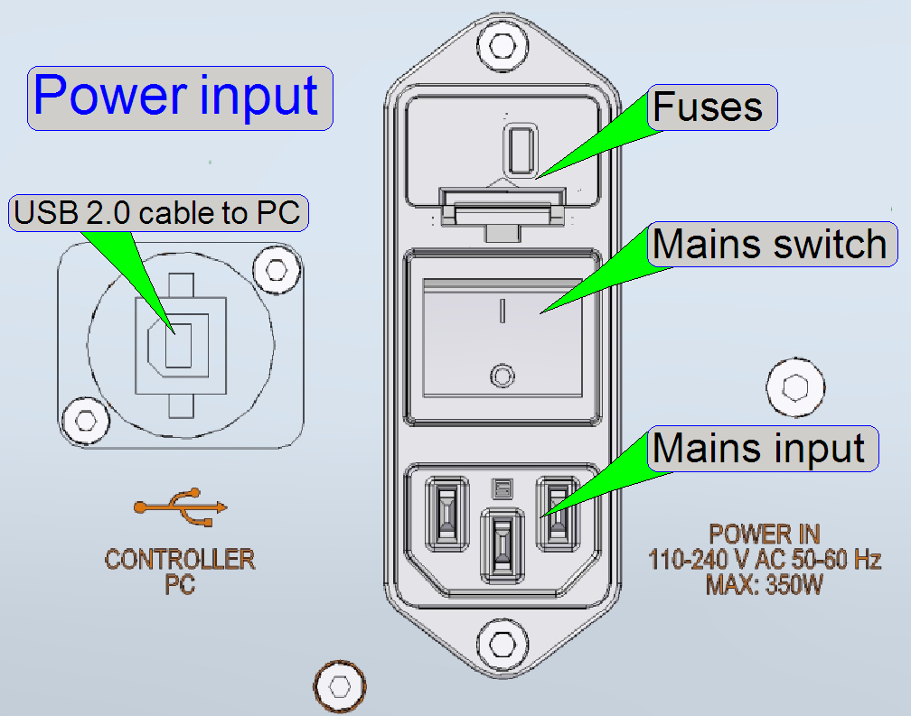
Power distribution
and switch board
������������������������������������������� Power
input and main switch
The power input connector and mains switch consists of:
- Power cord
connector (Mains input)
- Mains switch
- Fuse housing
with fuses
The double-pole mains switch disconnects the mains power from the
internal power supply.
Each pole is secured by a slow-blow fuse of T3.15 A / 250V.
230V~
or 100V~
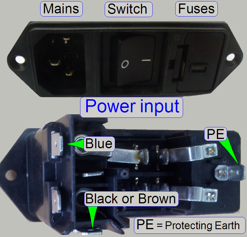 The alteration of
the mains power input in the range from 100V~ to 240V~ is reduced to the use of
the appropriate mains power cable (additionally, various connector outlet
constructions are used in different countries worldwide)!
The alteration of
the mains power input in the range from 100V~ to 240V~ is reduced to the use of
the appropriate mains power cable (additionally, various connector outlet
constructions are used in different countries worldwide)!
If the mains power is changed from 230V~ to 100V~ or vice versa, no
alterations are required inside the scanner; the change of the mains power is
fully handled by the input voltage range of the power supply; see also �Power supply TDK -Lambda�.
More information can be found in the �Power
input gallery� and the �Power input
slide show�
Check
or replace fuses
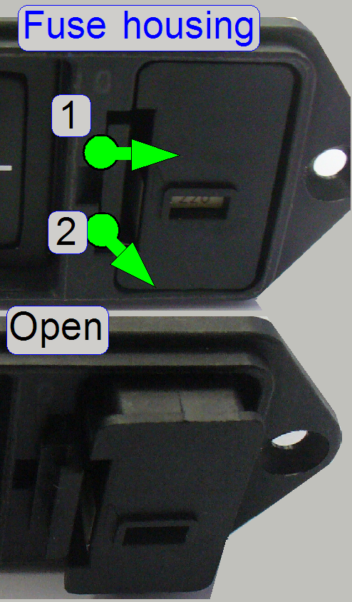 Disconnect
the power cable.
Disconnect
the power cable.- Open the fuse
housing and remove the fuse container.
�
Push the fuse container lock guide (1) to the center
of the fuse container (e.g. with a flat screw driver) and pull it out (2) of its
housing.
- If the fuses
are dismounted, please use an Ohmmeter to
check the fuses.
- If a fuse
exchange is necessary, please use always a slow-blow fuse of T3.15 A /
250V (100V~ or 230V~ power input is unimportant).
More information can be found in the �Power
input gallery� and the �Power input
slide show�
Power supply TDK -Lambda
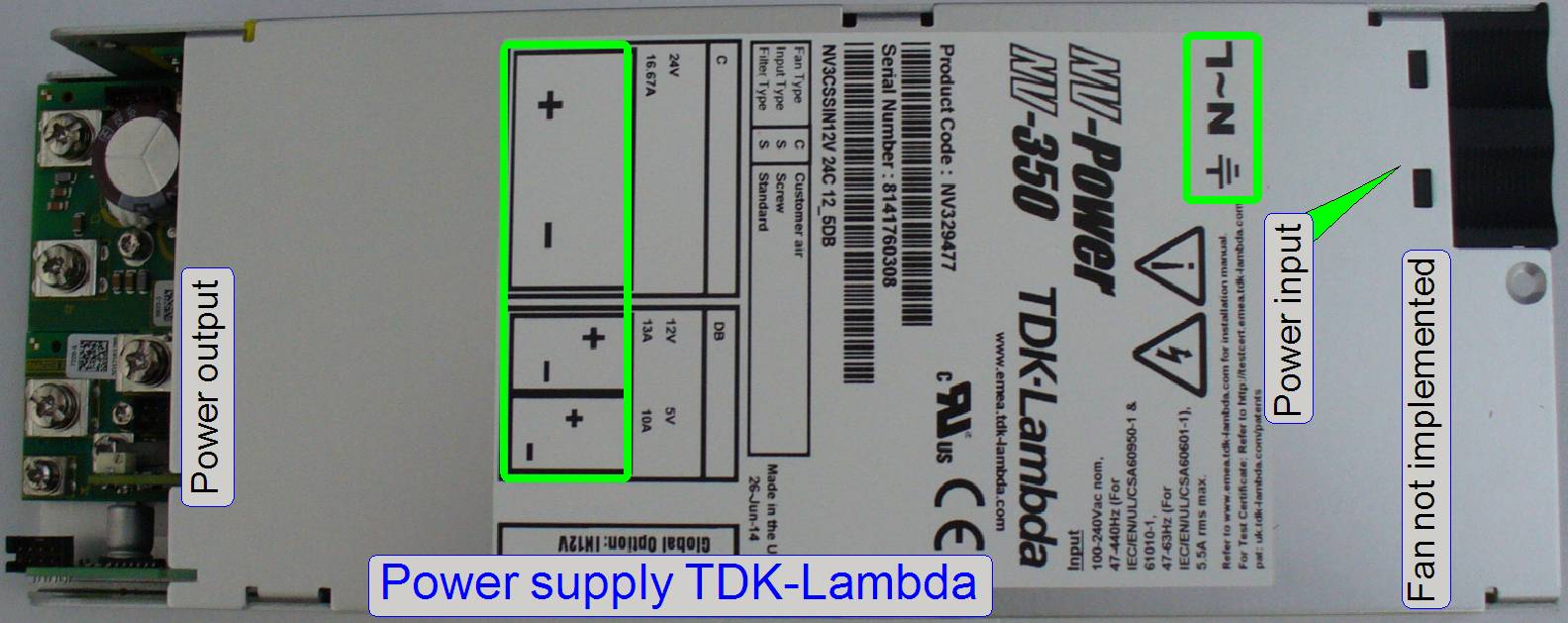

The internal OEM power
supply TDK-Lambda with an input voltage range of 90V~ to 264V~ AC, an input
frequency of 47Hz ~ 63Hz and output voltages of 5V-, 12V- and
24V- DC supplies the internal units of the PCON with power. Inside the
controller units (USB, X-, Y-, Z-motor controller, Power distribution board and
some stepper motors) a local power supply is located and these create further,
required voltages.
�
The power supply is short circuit protected.
�
The �Housing Switch� switch is used to switch off the
entire scanner if mechanical jamming or any other emergency situation occurs!
�
If the input voltage is changed from 230V~ to 100V~ or
vice versa, no alterations are required inside the scanner!
Remark
The fan of the power supply is removed in the PCON; the cooling of the
components is done by the central
fan of the power tower!
Power
input
�  Press the power
input cover a bit downward until the clamps (1) are disconnected from the upper
housing part and remove the cover.
Press the power
input cover a bit downward until the clamps (1) are disconnected from the upper
housing part and remove the cover.
� Connect the power
wires as shown (2).
� Fit the parts (a)
into the slots of the base cover and the clamps (b) into the appropriate slots
of the top cover.
See also:������ �Installation manual���������� (in more languages); stored in this
description
Output voltages; power
- 5V- /10A DC
- 12V- / 13A DC
- 24V- / 18.75A
DC
The outputs are short circuit protected and are ground independent (the
minus pole is not connected to GND)
so each voltage has a plus (+) and a minus (-) pole.
See also:������ Power_supply_tdk_Lambda_Data_Sheet.pdf� (stored in this description) and
����������������������� Power_supply_tdk_Lambda_App.
Notes.pdf��� (stored in this
description)
Housing Switch and standby
 The Housing Switch
inhibits and stops the switching power supply by the help of a relay, but the
mains voltage of 110V~ or 230V~ is not interrupted; the power supply goes to
standby!
The Housing Switch
inhibits and stops the switching power supply by the help of a relay, but the
mains voltage of 110V~ or 230V~ is not interrupted; the power supply goes to
standby!
By shorting the 2 pins �
If there is no connection between the two pins (or the standby option is
not used), the power supply is running continuously.
- These two
pins will be shorted via a relay, if the �Housing Switch� is active /
closed!
See also:������ Switch �Housing Switch�
Housing
Switch
 The Housing Switch
is situated in the left handed side wall of the scanner and is used to inhibit
the power supply; the power distribution is interrupted and all movements are
stopped immediately.
The Housing Switch
is situated in the left handed side wall of the scanner and is used to inhibit
the power supply; the power distribution is interrupted and all movements are
stopped immediately.
- If the power
is supplied again to the scanner, the software has to be
started again!
See also:������ Switch �Housing Switch� and �Power LED�
Power distribution and
switch board
 The power outputs
can be switched by software; so momentarily unused units can be switched off,
or if any emergency event occurred, all outputs may be disabled.
The power outputs
can be switched by software; so momentarily unused units can be switched off,
or if any emergency event occurred, all outputs may be disabled.
The outputs are switched by the use of relays.
The communication between software and the power distribution board is
realized with the control bus connector; this is connected to the USB
controller and is used to switch on / off the power outputs and to transfer
status information to the USB-controller.
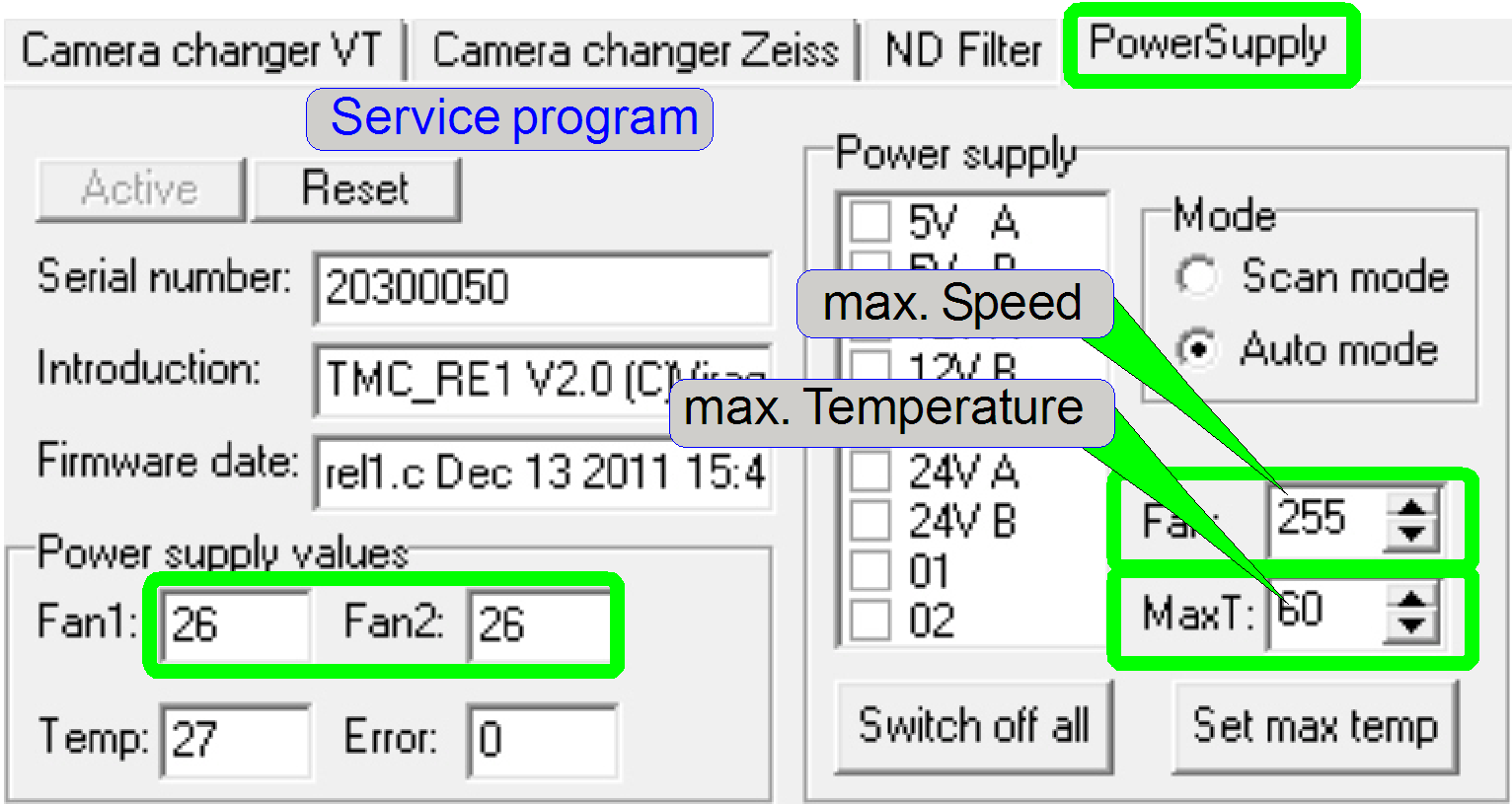
The temperature sensor input controls the fan output directly, without
any scan software control, bat the temperature value and the fan speed can be
read from the software; see also the service program, Low level service, power
supply. The fan speed is controlled via the PIC on this switch board, depending
on the sensed temperature value.
�
Enable or disable of the
switch board
For technical enhancements and upgrades, the type of the entire �Power
distribution & switch board� can be defined or the board might be disabled.
The relevant parameter and value is found in the section [Microscope] of the file �MicroscopeConfiguration.ini�.
To enable the switch board:
PowerSwitchBoardType=PowerSwitchBoard_Type1
Actually, the most recent
�Type1� is used.
To disable the switch board:
PowerSwitchBoardType=PowerSwitchBoard_None
Usually, the board is enabled.
If the entire �Power distribution and switch board� is disabled, the power
supply for the camera and all other connected units is disabled; the scanner
will not start correctly or the powering of the appropriate units have to be
realized otherwise; e.g. with external power supplies.
 1= reserve 5V-
output
1= reserve 5V-
output
2= reserve 5V- output
3= Power output 12V- ������ for the
logo LEDs in the front of the
housing
4= Power output 12V- ������ for the
PCO.edge
scan camera
5= Power output 24V- ������ switches
the current amplifier
for Lumencor� SPECTRA.
6= Power output 24V-������� switches
the Aventos servo drive
to drive the motorized front door
7= reserve switch1
8= reserve switch2
9= reserve 24V- output
5V= Power input from the TDK-Lambda power supply
12V= Power input from the TDK-Lambda power supply
24V= Power input from the TDK-Lambda power supply
The switched outputs are ground independent (the minus pole is not
connected to GND) so each voltage has a plus (+) and a minus (-) pole.
The board is found in the �Power tower� see also: Distribution
and switch board
Connectors Fan1 and Fan2
Via the connector �Fan
Temperature sensor input
The temperature sensor input is an I2C bus input and the
temperature sensor is connected here.
Current amplifier for Lumencor SPECTRA light engine�
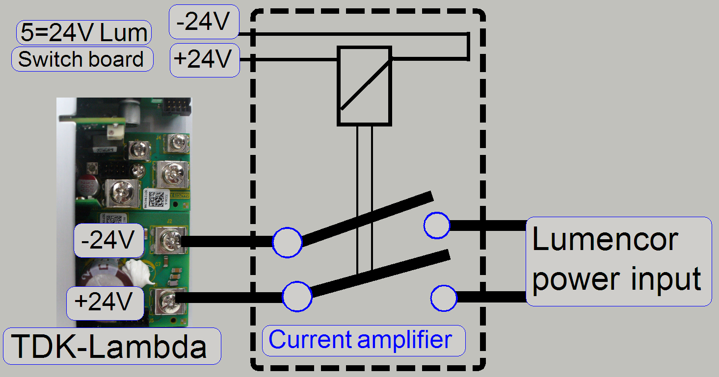 The current (power)
amplifier is realized by the use of a relay; it is switched on or off by the
output 5 of the �Power distribution and switch board�.
The current (power)
amplifier is realized by the use of a relay; it is switched on or off by the
output 5 of the �Power distribution and switch board�.
Because the relay on the �Power distribution and switch board� output 5
can not handle the required current of 5A DC a second relay is used.
The relay is found in the �Power tower� see also: Power amplifier
������������������������������������������� Temperature
 The temperature inside
the Power tower is sensed via a temperature sensor by the help of the PIC on
the switch board.
The temperature inside
the Power tower is sensed via a temperature sensor by the help of the PIC on
the switch board.
Probably errors may be:
- Temperature
sensor is not connected; any wire is broken or has no contact.
- Sensor is
defective.
- Power distribution
and switch board is defective.
See also:������ �Temperature sensor�
�Temperature sensor,
fan and fan control
 Because the fan of
the power supply is removed and cameras needs cooling (their temperature must
not exceed 60º C (140º F)), temperature sensing and
active cooling of the scanner is required.
Because the fan of
the power supply is removed and cameras needs cooling (their temperature must
not exceed 60º C (140º F)), temperature sensing and
active cooling of the scanner is required.
The sensed temperature value is used to control the speed of the fans
directly; without any interaction of the scan software �SlideScanner.exe�.
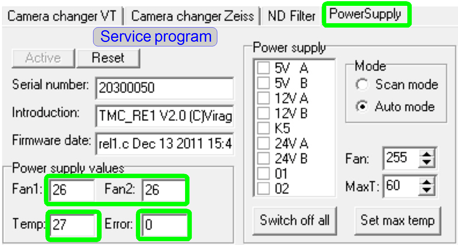
In the service program, the sensed temperature is shown in [ºC],
the fan speed is shown in a value between 1 and 255; 255 is the full speed of
the fan.
- The sensed
temperature value and the fan speed can be read with the service program
any time.
If the field �Error� is different from zero, a HW error exists in the
temperature sensor and fan control electronics; depending on the error code.
Error codes:
16������ Fan error; the spinning speed of the fan
is too slow; the fan blades moving too strong; they have too much resistance in
the bearing.
32������ Fan error; the blades of the fan are not
spinning; check cabling, connection; try to rotate the fan blades manually;
check for any mechanical reason also.
64������ The temperature of 60º C (140º F)
reached; check and clean the dust filter of the fan; check the fan�s connection
and the movement of the blades also.
128���� Power tower overheated; the relays are
switching off; the power to the connected units is interrupted; the temperature
reached 70º C.
� Because the error
bits are arranged in a byte, other values are possible if more errors existing
at the same time; e.g. 96= 64 + 32.
� If the units are
switched off by overheating, the scan software SlideScanner.exe shows the error
message
�Error occurred�
and stops working.
�������������������������������� Power Fan
 The spinning of
the blades is recognized by the PIC.
The spinning of
the blades is recognized by the PIC.
Probably fan errors may be:
- The signal of
the fan spinning sensor (situated inside the fan) is not recognized by the
fan control logic, because the fan is not or not well connected; the fan
blades does not rotate (any mechanical or cabling reason) or the fan is
defective.
- If the fan
speed is too slow please check and clean the dust and particle filters or
the fan blades moving too strong; they have too much resistance in the
bearing (fan goes defective).
- The power
distribution and switch board is defective.
See also:������ �The fan�
The Fan with dust filter is found in the �Power tower� from beneath; see
also: Construction_2
������������������������������������������� Aventos servo drive unit
 The Aventos servo
drive unit is used on the left side of the front door mechanics to open and close
the front door. The unit gets its power of 24V- / 1.4A from the output 6 of the
�Power
distribution and switch board�.
The Aventos servo
drive unit is used on the left side of the front door mechanics to open and close
the front door. The unit gets its power of 24V- / 1.4A from the output 6 of the
�Power
distribution and switch board�.
By disabling the power output via software, the opening of the front
door can be prohibited. The front door may be opened by the user only in
specified states of the scanner software; e.g. for filling the immersion liquid
feeder.
See also:������ �Aventos HL aluminum frame door
application� and
����������������������� �Aventos Lift Systems������������������������������������������ .pdf-files;
stored
See Also:����� �Front
door� in the chapter �Housing�
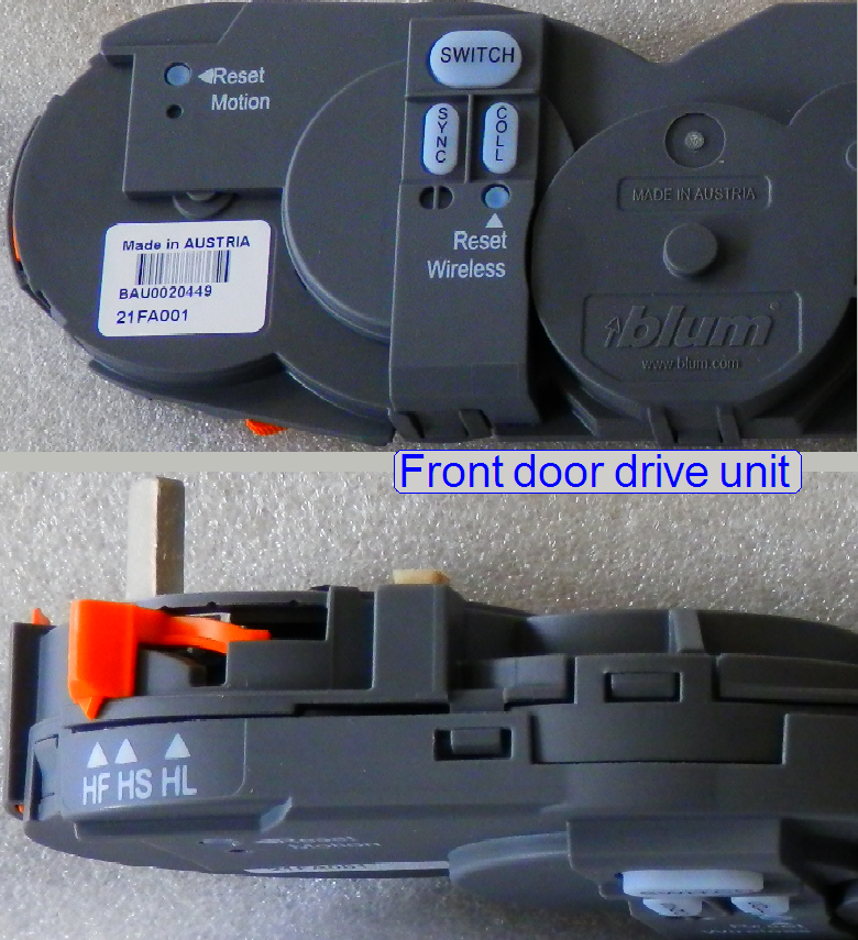 The button
�SWITCH� is used to realize the communication between the wireless switch and
the Aventos drive unit.
The button
�SWITCH� is used to realize the communication between the wireless switch and
the Aventos drive unit.
�SYNC� is used to synchronize 2 or more Aventos drive units (not used in
PCON).
The button �COLL� (collision) is not used in our implementation.
A detailed description (exclusively in movie and pictures) about
installation, working principles, adjustments, communication setup and switch
battery replacement of the servo unit and the switches can be found on YouTube!
Watch video on YouTube:������������������� Blum Aventos Servo Drive
(please open in new window!)
HF,
HL
� In the state HF
the drive unit can be dismounted or mounted to the mechanics.
� In the state HL,
the unit is physically connected to the mechanics, this is the normal operating
state.
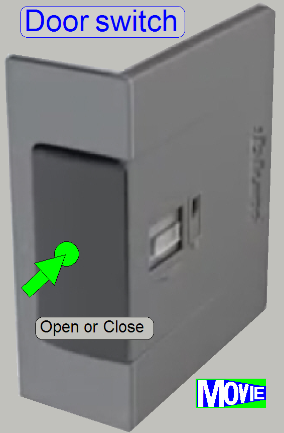
The
door switch is used to operate the Aventos servo unit. By pushing the button, a
wireless connection between button and servo unit is realized and, depending on
the actual state, the door will be opened or closed respectively.
Watch also video on YouTube:���������� Blum Aventos Servo Drive
(please open in new window!)
 Usually, the synchronization
between drive unit and switch is done during installation of the unit.
Usually, the synchronization
between drive unit and switch is done during installation of the unit.
If the synchronization between switch and controller of the drive unit
is lost, the procedure should be executed.
� The
synchronization procedure assigns the switches to the controller unit.
� If the
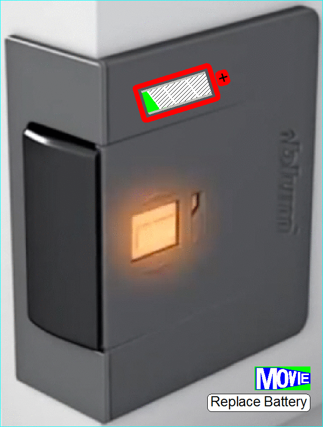
LED in the switch is flashing, the battery needs to be replaced
� If the battery was
replaced, synchronization between switch and aventos unit might be required!
Watch also video on YouTube:���������� Blum Aventos Servo Drive
(please open in new window!)
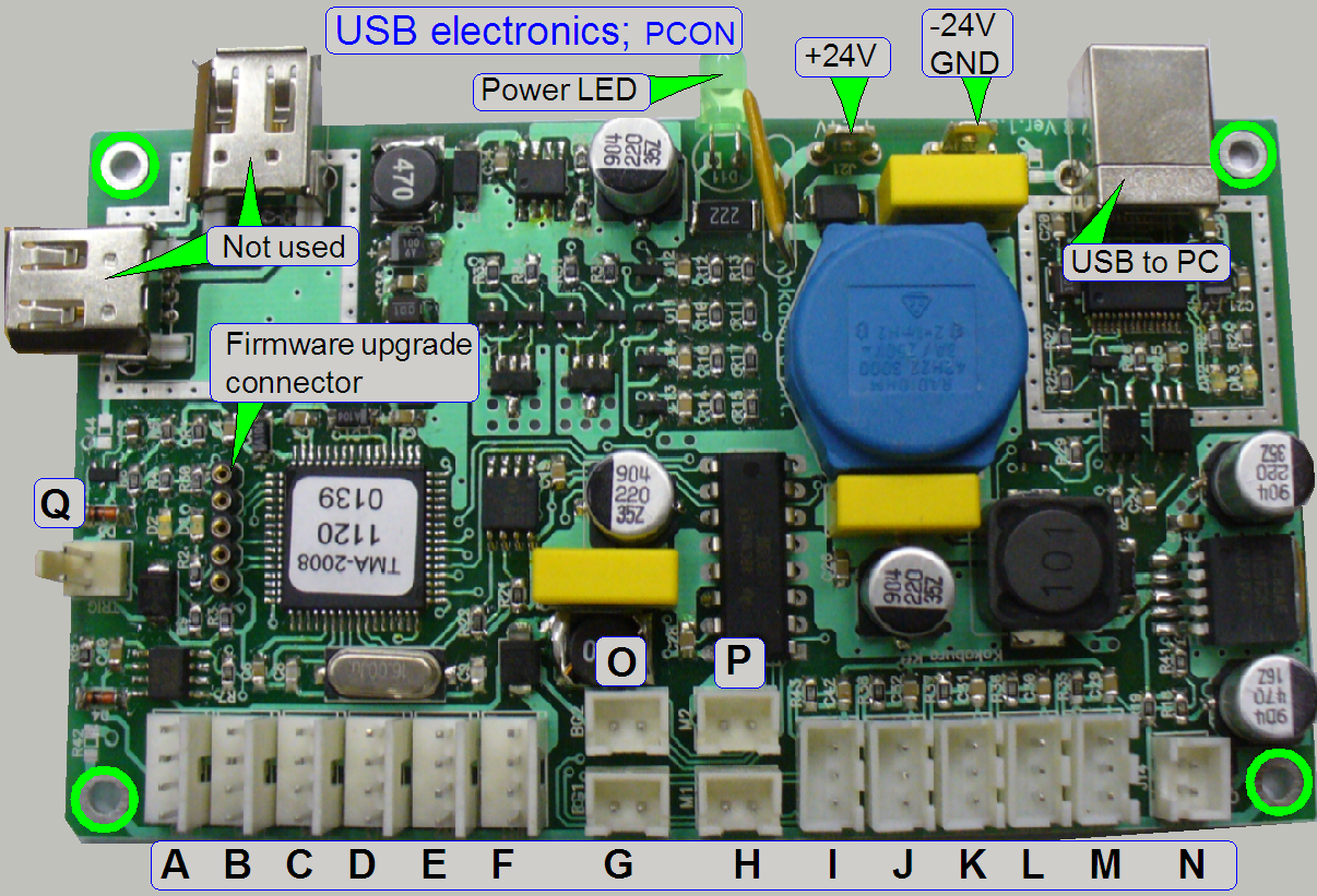
Nominal �wire to board�
connections
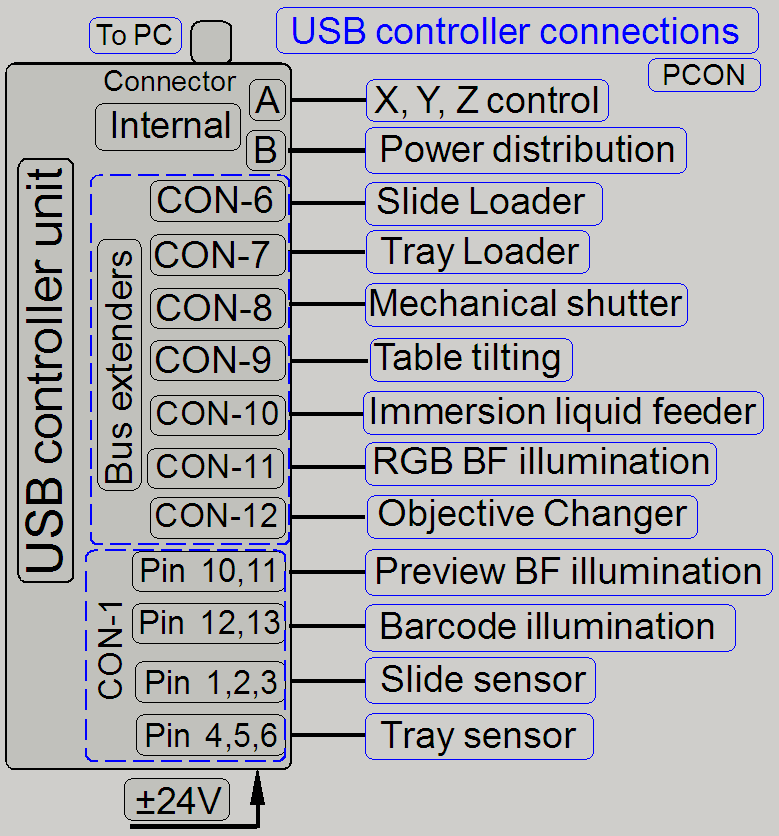 The USB controller
connects, supplies and controls all the addressable units and outputs; these
are:
The USB controller
connects, supplies and controls all the addressable units and outputs; these
are:
�
- X-Y-Z-motor control
- Power distribution
& switch board
- Tray loader
- Slide Loader
- Mechanical shutter
- Brightfield preview
illumination
- RGB BF illumination
unit
- Objective changer unit (OC)
- Immersion liquid
feeder
- Table tilting
- Preview BF
illumination
- Barcode illumination
- Tray sensor
- Slide sensor
- The USB controller
gets its +-24V power directly from the tdk lambda OEM
power supply.
The USB controller receives the command for the units from the program
SlideScanner.exe (the scan program) or the SlideScannerService.exe (the service program) via the USB
control port of the PC and the USB cable.
All units contain separate electronics and are connected via a bus
system. To differentiate the units, connected to the USB controller, all
stepper motor electronics and the unit-controller as well has an address. Each data transfer
starts with the specified address for the unit and is listen by all units at
the same time, but only this unit receives the message, which internal address
and the message address is identical. The stepper motor electronics can receive
commands (number of steps to go and direction) and can send status information
(desired position reached and the status of the sensors Home1 and Home2).� The status information is sent via the USB
cable to the software, hereby the address of the unit is used also.
With this solution it is possible to change the �Hirschmann� connection
with another �Hirschmann� cable (e.g. for fault detection) without any risk or
functional restrictions. The label of the cable for digital electronics has no
reason in functionality; it differentiates the cables from each other instead,
because some cables are shorter than others.
Important
The
construction of the controller powering on the board does allow the drive of
maximal 3 stepper motors at the same time!
� Please
take this into account, if you are working with the service program and the batch
test program module!
 Nominal
�wire to board� connector positions:
Nominal
�wire to board� connector positions:
B� =�� Power distribution and
switch board
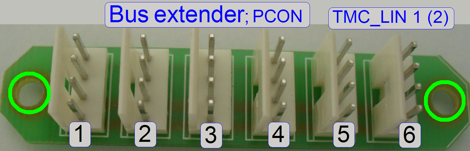
C� =�� Bus extender� TMC_LIN 1 (2)
D� =�� Bus extender� TMC_LIN 1 (1)
E� =�� Reserve
F� =�� Reserve
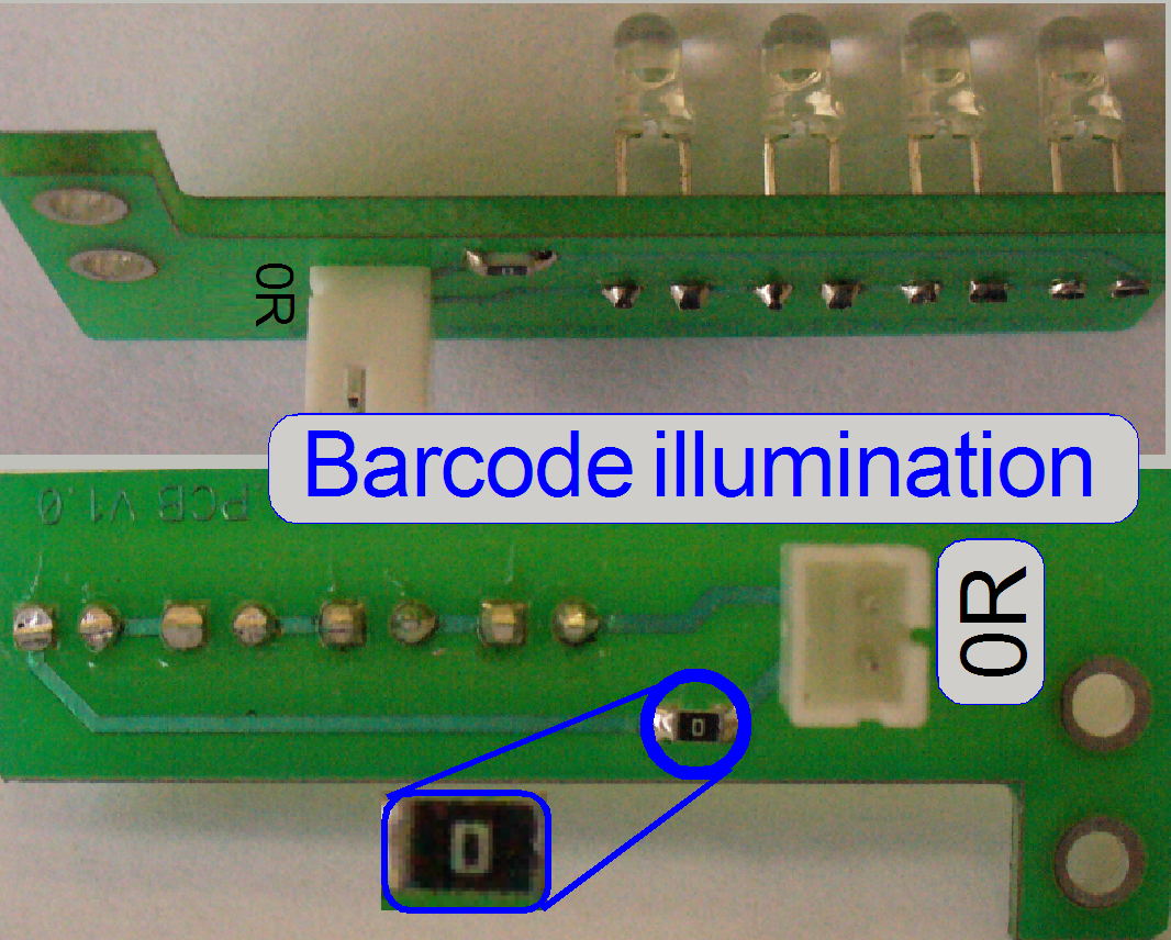
G� =�� Barcode illumination;���������� CF01D����������
H� =�� Reserve
I��� =�� Reserve
J�� =�� Reserve
K� =�� Reserve
L�� =�� Tray sensor = TMC-HAL1(2)���������� CF01E
M� =�� Slide sensor = TMC-HAL1(1)��������� CF01F
N� =�� Reserve
O� =�� Brightfield preview
(background) illumination;�� CF01A
P� =�� Reserve
Q� =�� Reserve
- The USB
controller gets its +-24V power directly from the tdk lambda
OEM power supply; the minus pole (-) is connected to the pin, named as
GND!
The USB controller unit is found in the �Power tower� see also: USB and Construction_3
USB to PC
The USB connection to the
rear connector is realized with an internal USB cable, see also: �USB� and �Rear wall�
Output
and sensor connections
|
Connection |
Connector |
Identifier |
Pins |
||
|
Sensors and illuminations |
CF01 |
+ |
- |
Signal |
|
|
Preview BF illumination |
CF01A |
10 |
11 |
|
|
|
Preview DF illumination |
CF01B |
12 |
13 |
|
|
|
Preview DF illumination |
CF01C |
14 |
15 |
|
|
|
Barcode illumination |
CF01D |
16 |
17 |
|
|
|
Tray sensor |
CF01E |
3 |
1 |
2 |
|
|
Slide sensor |
CF01F |
6 |
4 |
5 |
|
� The
length of the cables is so dimensioned, that only the specified unit can be
reached easily.
The addressable units are also connected via the �Bus extender� because
the number of connected units increased. The bus contains the power supply for
the unit (24V-) and the serial bus (I2 C). Via the
serial bus the connected units are addressed, receive command and control
information and returns status information.
Each connected unit contains a local power supply to create further,
required voltages.
Nominal connections of TMC_LIN 1 (1)
1 =����� Connector �D� of the �USB controller�
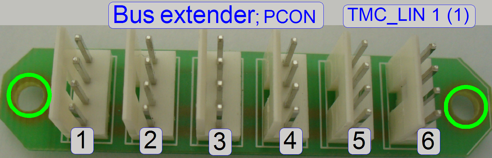 2 =����� Slide loader motor control
3 =����� Tray loader motor control
4 =����� Tilting motor control
5 =����� Immersion liquid feeder
control
6 =����� shutter motor control
� Positions may be
changed without any functional risk or restrictions!
Nominal connections of TMC_LIN 1 (2)
1 = ���� Connector �C� of the �USB controller�
 2 =����� RGB brightfield illumination control
3 =����� Camera changer unit
control
4 =����� Reserve (NC)
5 =����� Reserve (NC)
6 =����� Reserve (NC)
� Positions may be
changed without any functional risk or restrictions!
The Bus extenders are found in the �Power tower� see also: �Bus extenders�
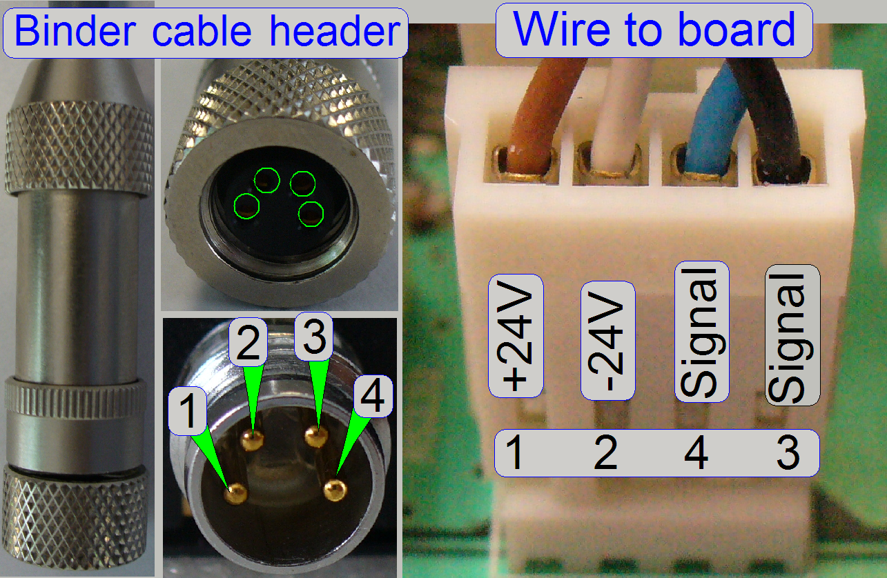 The addressable units are
connected with the �Binder� connector (except the Power distribution and switch
board); the connection is secured with a knurled nut. On the other end of the
cable a �wire to board� connector is used.
The addressable units are
connected with the �Binder� connector (except the Power distribution and switch
board); the connection is secured with a knurled nut. On the other end of the
cable a �wire to board� connector is used.
Important
Please do not use pliers to loosen or tighten the cable header lock nut.
If there is too much force used on the connectors, the soldering of the
connector may be destroyed and broken and the appropriate motor or unit will
not work.
|
Addresses of scanner
units |
||
|
Unit |
Address |
Type |
|
X-Y-Z
control |
00 |
C_P |
|
USB-controller |
01 |
All |
|
DC-controller |
02 |
P_S_M_D
|
|
X-motor |
03 |
S_M_D |
|
Y-motor |
04 |
S_M_D |
|
Z-motor |
05 |
S_M_D |
|
Turret
unit |
06 |
S_M_P |
|
Tray
loader motor |
07 |
M_C |
|
Slide
loader motor |
08 |
M_C |
|
Objective
changer |
09 |
C_P_S_M
|
|
Camera
changer |
10 |
P |
|
RGB
illumination |
11 |
C |
|
Reserve |
12 |
---- |
|
Immersion
liquid unit |
13 |
C |
|
Mechanical
shutter |
14 |
C |
|
Switch
board |
15 |
C_P |
|
Legend:
C=Confocal; P=P250; S=SCAN; M= |
||
The addresses are used by the scan program and the
service program to select the unit; these addresses are programmed into the
specified unit and can be changed via special
software only. It is important, that none of these addresses should
exist twice inside of one Pannoramic scanner, otherwise command and status
mismatch occurs.
If data transfer is in progress, all addressable units
listen to the address of the data stream.
If the address of the unit is identical with the
address of the data stream, the addressed unit is found and this receives the
information.
|
Unit |
Connector |
Identifier |
|
Sensors and illuminations |
CF01 |
|
|
Power for PCO.edge� camera |
CF02 |
|
|
Cable to the housing |
CF03 |
|
|
Power for Lumencor SPECTRA |
CF06 |
|
|
Power for the Aurox CC 88 (not shown here) |
|
|
|
Nominal bus cable header positions |
||
|
Slide Loader |
CF04 |
|
|
Tray Loader |
CF11 |
|
|
Mechanical Shutter |
CF10 |
|
|
Table tilting |
CF09 |
|
|
Immersion liquid feeder |
CF05 |
|
|
RGB BF illumination |
CF08 |
|
|
Objective changer unit |
CF07 |
|
� The length of
the cables is so dimensioned, that every bus connector may be reached with any
bus cable header.
� Positions of the
bus cables may be changed without any risk or functional restrictions; e.g. for
fault detection!
Housing
connector
Pin assignments can be found in the table �CONN3�
 The power LED is
lighting if the power is supplied to the Pannoramic scanner (the power cable is
connected; the Mains switch and the Housing Switch are switched on).
The power LED is
lighting if the power is supplied to the Pannoramic scanner (the power cable is
connected; the Mains switch and the Housing Switch are switched on).
If the power LED is not lighting
- Check the
mains power in the connector outlet.
- Check the power cable and
its right connection.
- Check the mains power
switch state on the rear.
- Check the Housing Switch state.
- Check the
fuses.
- Check the
conductivity and functionality of the Housing Switch relay
- Check the
conductivity of components �Power input and
mains switch�
- Check the
output voltages of the power supply.
If the power LED is flashing
If there is a shortcut inside the scanner, the power supply is switched off
by overload!
Every 200 ms the power supply will switch on itself and tries to supply
the output voltages. This behavior makes slightly flashing the power LED; the
fan may rotate.
- Switch off the mains power
of the power supply and measure with the ohmmeter
the resistance between the positive and the negative pole of the output
voltages 24V, 12V and 5V of the power supply �tdk Lambda�.
(Do not measure the +pole in relation to ground, because the voltages are
ground independent!)
- If the
resistance is 1 or 2ohms only or nearly 0 ohm, the defective (shortcut)
output is found.
- Remove the
power output connectors of the �Power
distribution and switch board� and switch on the power supply again
and measure any output voltage of the power supply.�
- Remove the
Power input connector of the �Power distribution and switch board� and
switch on the power supply again and measure any output voltage of the
power supply.
- Remove the
power output connections of +24V of the power supply �tdk Lambda�
and switch on the power supply again and measure any output voltage of the
power supply.
- Remove the
power output connections of +12V of the power supply �tdk Lambda� and
switch on the power supply again and measure any output voltage of the
power supply.
- Remove the
power output connections of +5V of the power supply �tdk Lambda� and
switch on the power supply again and measure any output voltage of the
power supply.
If the shortcut disappeared, measure the resistance of the disconnected
paths / wires with the ohmmeter against the negative pole of the appropriate
output voltage or reconnect the appropriate connections singly, separately to
find the faulty path.
 The
EEPROM stores the scanner specific parameters and these are collected in the
files MicroscopeConfiguration.ini and
MicroscopeSettings.ini. To ensure an always proper functioning of the scanner,
the content of the EEPROM should be updated after adjustments are done or units
are exchanged and parameter values are modified. The EEPROM is a part of the
USB controllers PCB.
The
EEPROM stores the scanner specific parameters and these are collected in the
files MicroscopeConfiguration.ini and
MicroscopeSettings.ini. To ensure an always proper functioning of the scanner,
the content of the EEPROM should be updated after adjustments are done or units
are exchanged and parameter values are modified. The EEPROM is a part of the
USB controllers PCB.
� To update the content, the EEPROM should
be cleared with the service program.
� If the scan software is started and the
EEPROM is empty, the content of the appropriate *.ini files will be written
automatically from the HDD into the EEPROM.
1.
 Start
the program �SlideScannerService.exe�.
Start
the program �SlideScannerService.exe�.
2.
Click in the field �Clear EEPROM� of the
selector menu.
3.
Answer the dialogue with �Yes�; then the
EEPROM is cleared.
4.
Exit the service program with �EXIT�
5.
Start the program SlideScanner.exe; the *.ini-files
will be automatically saved from the appropriate HDD folder into the EEPROM
during startup of the program.
Compressed content of the EEPROM
The compression of the EEPROM content is required since the software
version 1.16, because there are newly implemented parameters and the capacity
of the EEPROM is limited to be 2kB.
� By compressing the
content, memory space is won.
In systems, delivered with the version 1.16 the modified handling of the
EEPROM content will not be noticed by the user; the files
�MicroscopeConfiguration.ini� and �MicroscopeSettings.ini� staying on the HDD
in uncompressed form.
� If the EEPROM
content is written, the files �MicroscopeConfiguration.ini� and
�MicroscopeSettings.ini� will be compressed before these are stored in the
EEPROM.
� If the EEPROM is
read, the content will be uncompressed before it is stored as file
�MicroscopeConfiguration.ini� and �MicroscopeSettings.ini� on the HDD.
If an upgrade is made (from the version 1.15 to the version 1.16) the
content in the EEPROM is uncompressed but the version 1.16 expects a compressed
content; therefore:
Before you are installing the software version 1.16
� Make sure; the
content of the files �MicroscopeConfiguration.ini� and �MicroscopeSettings.ini�
is the most recent content on the HDD.
� Save these files
to a save place
Install the software version 1.16
� Start the program
�SlideScanner.exe� first time.
� The compression of
the EEPROM content will be done automatically.
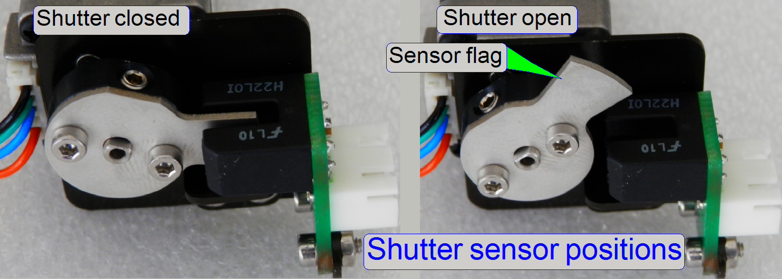
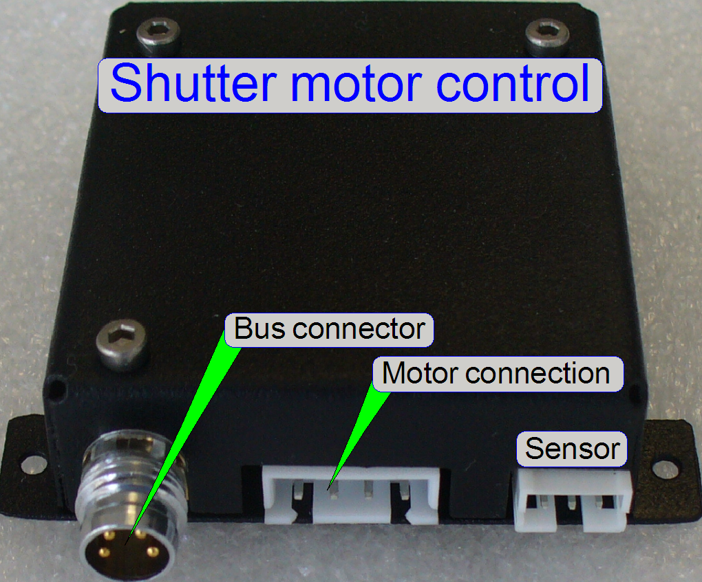
 The
mechanical shutter is used to cover the condenser optics during the Fluorescent
scan session and other, not brightfield illuminated scan sessions.
The
mechanical shutter is used to cover the condenser optics during the Fluorescent
scan session and other, not brightfield illuminated scan sessions.
The shutter mechanics was removed from the focus unit
(in relation to previous scanners) and the shutter motor is placed onto the
scanner plate from beneath.
� The
possible movement of the shutter guide is approximately 110º and this is
defined by the number of steps, executed between shutter on to shutter off and
vice versa.
See also:������ �Shutter
mechanics�, �Focus unit�, �Mechanical shutter� and �Shutter sensor�
Define the shutter open and closed position by setting
the values of the sensor in [Motor steps] in the file
�MicroscopeConfiguration.ini�.
�  Check
the correct values with the service program!
Check
the correct values with the service program!
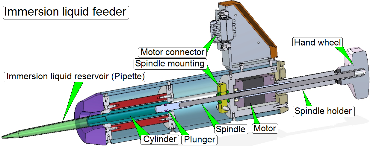 The
immersion liquid feeder is used to spend drops of distilled water onto the
cover slip of the tissue to be scanned with the 40x immersion liquid objective.
The
immersion liquid feeder is used to spend drops of distilled water onto the
cover slip of the tissue to be scanned with the 40x immersion liquid objective.
The distilled water is filled manually into the
pipette and will be spend automatically by the use of the stepper motor before
the scan process starts.
The stepper motor has a resolution of 200 full
steps/revolution (3200 micro steps) and is used to drive the spindle and so the
plunger.
See also:������ �Liquid feeder stepper
motor�, �Immersion
liquid feeder unit� and �Image gallery�
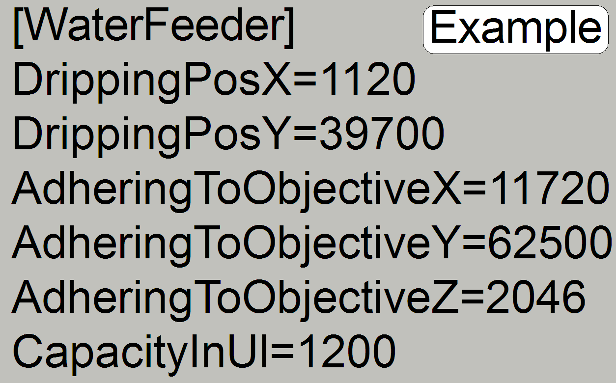
� Values in the file
�MicroscopeConfiguration.ini� (example)
� Please
connect the appropriate cable to the corresponding connector!
Connected
LEDs
5W HI-POWER LED White���������� Data Sheet
Power:���������������������� 5W
Forward Voltage:���� 3.8V�������������� (4.3V max peak)
Current:�������������������� 1400mA�������� (1500mA max peak)
�
Driving LED without heat sinking device is forbidden.
� It is strongly
recommended that the temperature of lead be not higher than 55ºC.
See also:������ �Power LED module�
and �Brightfield RGB
illumination unit�
X-Y-Z-motor control
electronics
The unit realizes the control, connections and interfacing of the
following units:
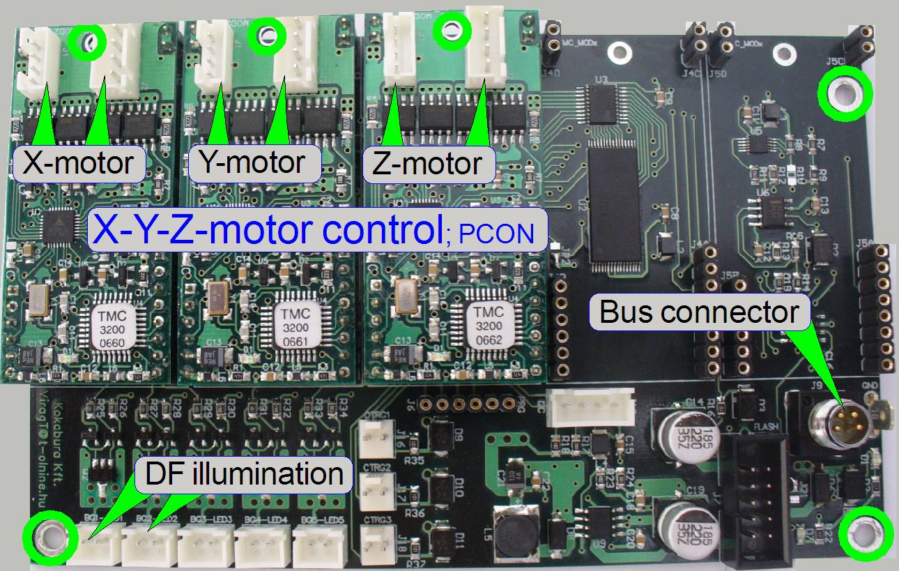
- X-motor
- Y-motor
- Z-motor
(focus)
- Darkfield illumination
- The power
supply and the control of the addressable unit are realized via the Bus
connector.
Darkfield illumination
connector
� The two connectors
�DF illumination� provide the power for the darkfield illumination and are
interchangeable; the intensity can not be affected.
� The connection to
the DFP illumination unit is realized with the pins 14 ~ 17 of the connector �CON1�
 The X-, Y-,
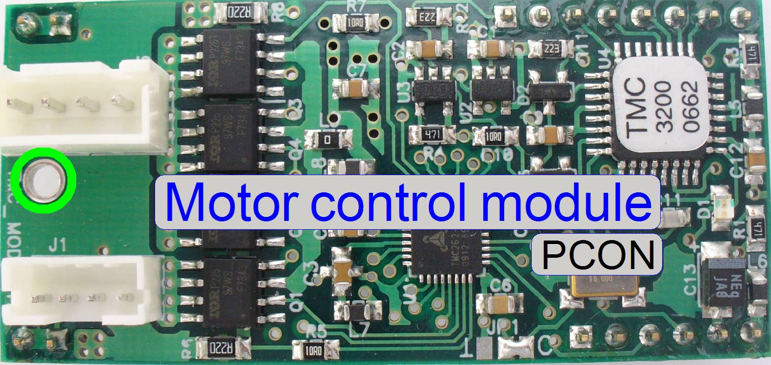
Z-stepper motor control electronics is realized with the appropriate
module; these motors itself does not contain control electronics.
The X-, Y-,
Z-stepper motor control electronics is realized with the appropriate
module; these motors itself does not contain control electronics.
- The motor
modules are all from the same type and are interchangeable without address
modifying.
 Important
Please do not use pliers to
loosen or tighten the cable header lock nuts. If there is too much force used
on the connectors, the soldering of the connector may be destroyed or broken
and the appropriate motor will not work or may working very noisy.
The wires of the appropriate
stepper motor as well as the wires of the sensors are directly connected to the
electronics via the motor cable headers.
The construction of the
connectors does not allow an interchanging of the two cables to each other, but
the motor can be connected to another module; e.g. for fault detection with the
service program.
�
The sensors Home1 and Home2 are also connected via the
motor cable headers.
More detailed information about the internal construction can be found
in the �Power tower slide show�
and �Power tower gallery�
|
Motor cable headers; working
connections |
||
|
Unit |
Connector |
Identifier |
|
Z-motor; female |
CF12 |
|
|
Z-motor; male |
CF13 |
|
|
Y-motor; female |
CF14 |
|
|
Y-motor; male |
CF15 |
|
|
X-motor; female |
CF16 |
|
|
X-motor; male |
CF17 |
|
|
Power for Aurox CC 88 |
|
|
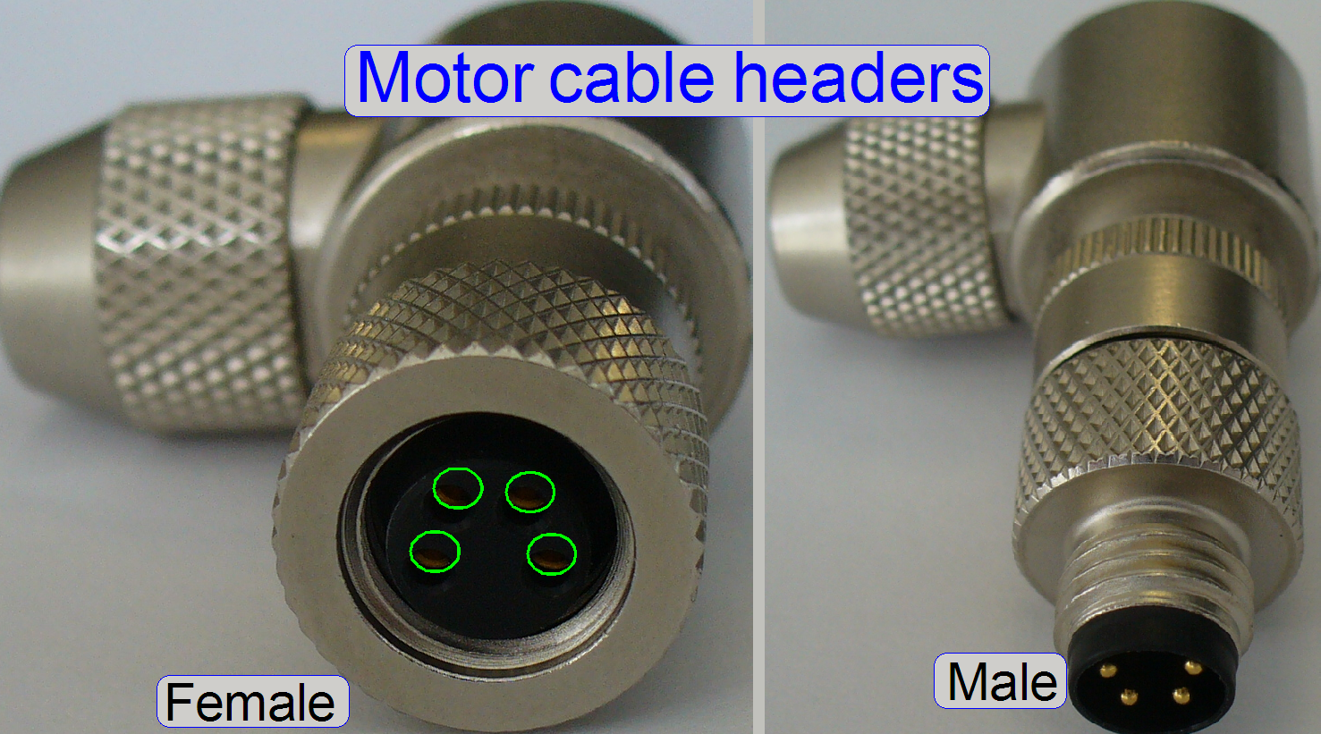
� The length of the cables
is so dimensioned, that every motor connector pair may be reached with any
motor cable header pair.
Important
� For
test purposes and fault detection, the motor cable header pair may be connected
to another motor output; e.g. the X-motor headers are connected to the Y-motor
output.
� In
this example, the service program Y-direction tools will be used to move the
X-stage!!
� Before
SlideScanner.exe will be started, the motor cable headers have to be connected
to their original, correct motor connection!
Stepper
motor
 See:����� Stepper
motors
See:����� Stepper
motors
About
basics, theory and principles please refer to:
http://www.solarbotics.net/library/pdflib/pdf/motorbas.pdf
Stepper
motor basics�������������������� (stored)
Drive circuit basics������������������������ (stored)
Stepper motor and driver�������������� (stored)
External
recirculation diodes������� (stored)
Stepper motor
driving�������������������� (stored)
Stepper motors 2011��������������������� (stored)
Background
(preview) brightfield illumination
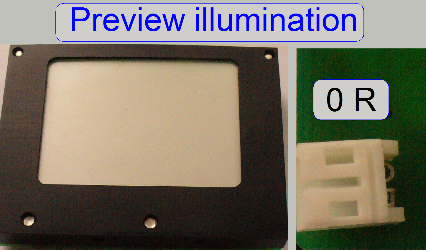 The
preview illumination consists of 6 LED�s and is
used to illuminate the scan area of the slide and makes so the sample visible
for the preview camera.
The
preview illumination consists of 6 LED�s and is
used to illuminate the scan area of the slide and makes so the sample visible
for the preview camera.
The preview illumination exists as a 0R version only.
The output for the preview illumination is driven by a
current generator. The intensity of the backlight can be adjusted in the range
between 1 and 255 (maximum) in the service program only, 0 means the backlight
is switched off. The parameter is removed since the software version 1.15 from
the file �MicroscopeConfiguration.ini� section [PreviewAndBarcodeScanning].
Connector
label:���� CF01A
 The
�Tray Sensor� and the �Slide Sensor� are
realized with Hall elements.
The
�Tray Sensor� and the �Slide Sensor� are
realized with Hall elements.
- If the south pole of a magnet is over the Hall element or the north
pole on the opposite side, the switch is closed and this state is
recognized by the software.
- If the polarity of the permanent magnet is inverted or a magnetic
field is not present, no action occurs.
- The sensors are so implemented, that the south pole of the
permanent magnet stays over the sensor surface if the action position is
reached.
� The
sensor position is often adjustable. For adjustment procedures see the
appropriate chapters.
� The
sensor does not need maintenance.
See also:������ Hall effect���������������� Wikipedia
����������������������� TLE4905L �������������� Datasheet; stored
|
Tray and
slide sensor |
||
|
Sensor |
Name |
Label |
|
Tray |
TMC-HAL1(2) |
CF01E |
|
Slide |
TMC-HAL1(1) |
CF01F |
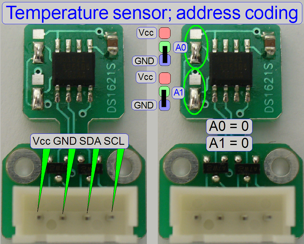
Voltage:�������� 3.6V ~ 5.5V max
Data sheet:�� DS1621S
Address coding
Because the sensor is
used in a bus system (I2C), the sensor needs an address; the address
have to be A0=A1=0.
� Other address
combinations may be used in other systems or in further solutions.
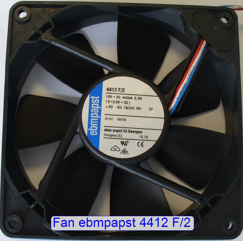
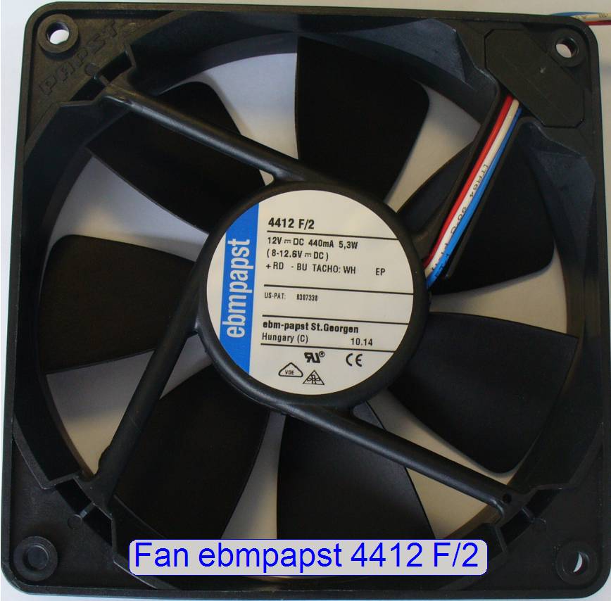 Type:���������������������������������� ebmpapst 4412
F/2
Type:���������������������������������� ebmpapst 4412
F/2
Power:������������������������������� 12V-DC 440mA;
5.2W with spinning sensor (operating range = 8V- to 15V)
Max spinning
speed:������ 2700 rpm
By control of the fan�s voltage via the PIC on the �Power
distribution and switch board�, the spinning speed of the blades will be
affected; and so the air quantity, blown into the scanner.
 The fan speed can
be calculated by the following formula:
The fan speed can
be calculated by the following formula:
Fan speed = (2700 / maximal speed
value) x actual value.
In the example on the right the fan speed is:
Fan speed = (2700 / 255) x 26 = 275
rpm.
See also:������ Power supply; Service program
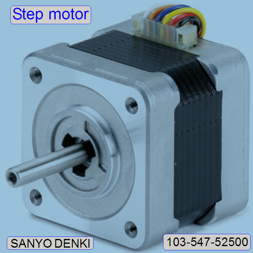
 Type:������������� Nanotec L2018S06054- T3.5X1
Power:���������� 4.3V � 0.8A
Resolution (full
steps):������ 200 steps / revolution
� The stepper motor is
used to rotate the spindle and spends so software controlled the immersion
liquid onto the cover slip via the plunger.
See also:������ �Motors� galery�
Liquid
feeder stepper motor control
Attention
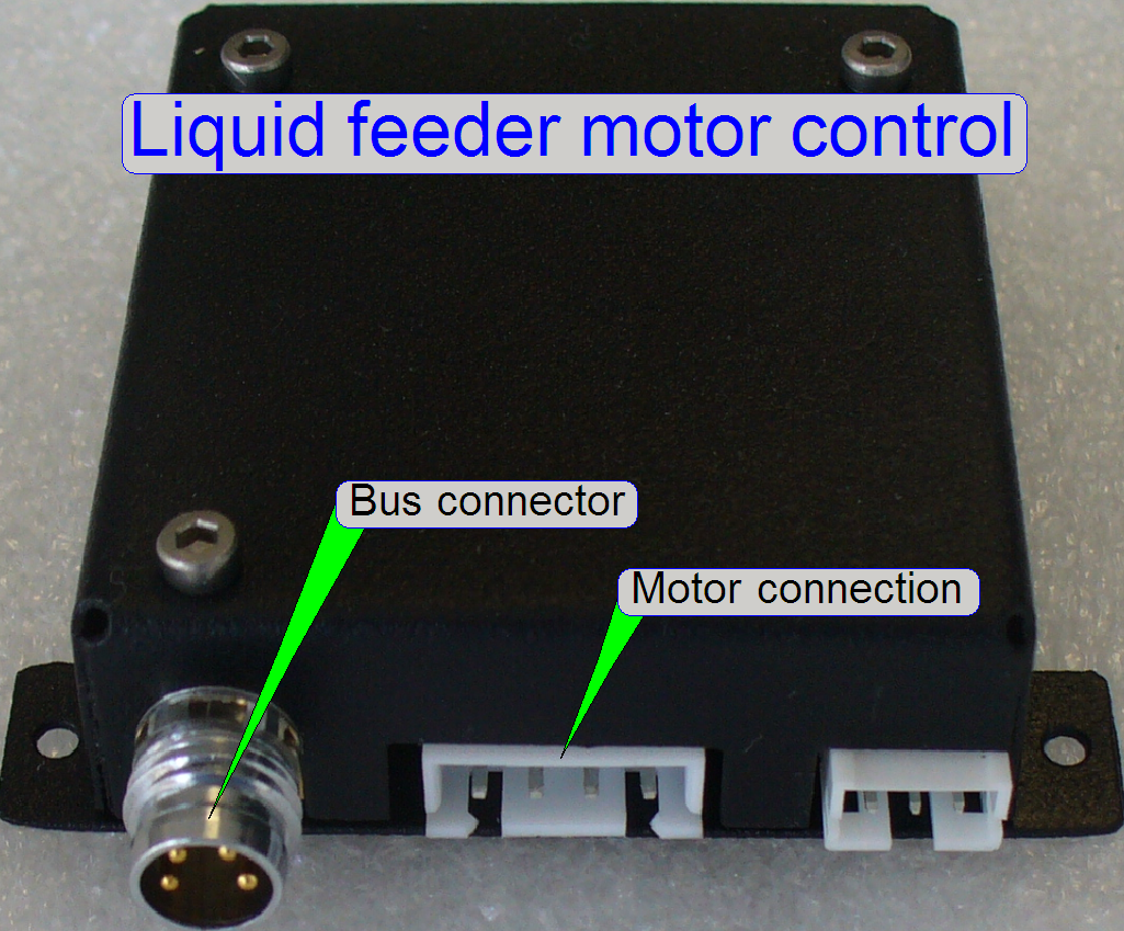 The PCB�s
construction of the �Liquid feeder control� and the �Shutter control� is
identical, but they have a different address!
The PCB�s
construction of the �Liquid feeder control� and the �Shutter control� is
identical, but they have a different address!
� From outside, the control units are
undistinguishable!
Address of �Liquid feeder control� ������ = ����� 13
Address of �Shutter control� ����������������� =������ 14
See also �Addresses� and �Address assigning tool�
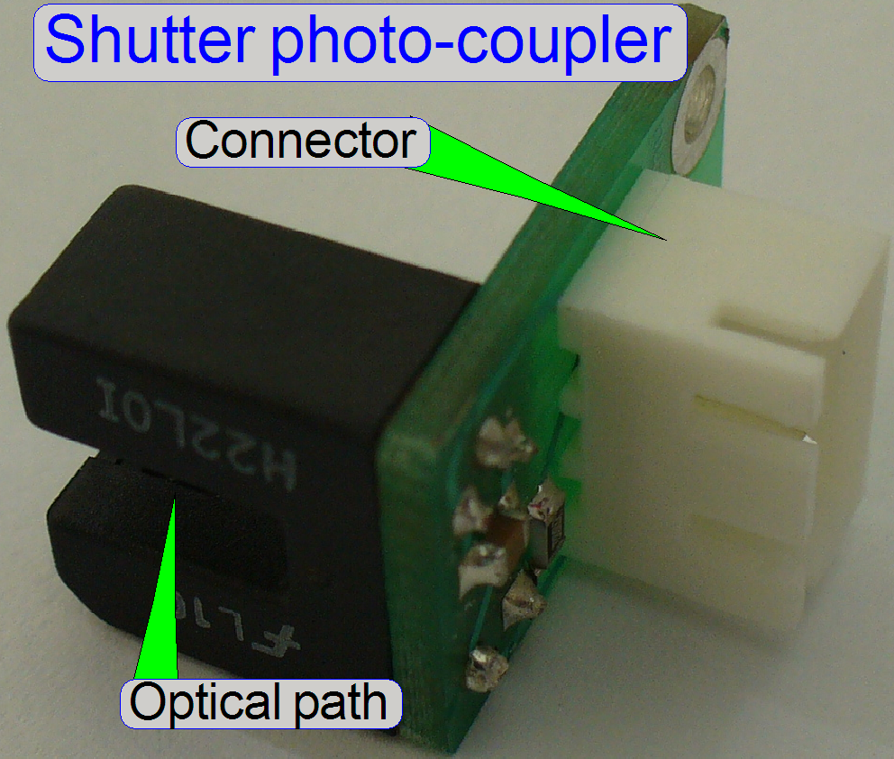
Coupler type:���������� H22L� Data sheet
The light path of the sensor is broken if the sensor
flag is moved against the limiter.
 If the
flag of the shutter sensor stays in the optical path of the photo-coupler, the
optical path is broken; this is also the Home position of the mechanical
construction.
If the
flag of the shutter sensor stays in the optical path of the photo-coupler, the
optical path is broken; this is also the Home position of the mechanical
construction.
To change the shutter position from on to off or vice
versa, the stepper motor is rotated by a predefined number of steps.
� The
Home position is identical with the position �Condenser cover on; (shutter
closed)�
� To operate
the shutter, the rotor of the stepper motor is rotated by about 350 steps.
A mechanical limiter ensures, that the stepper motor
can not be moved in negative direction,
By adjusting the shutter clamp position and the sensor
clamp position, defined requirements are fulfilled.
 See
also:������ �Mechanical shutter� and
�Shutter mechanics�
See
also:������ �Mechanical shutter� and
�Shutter mechanics�

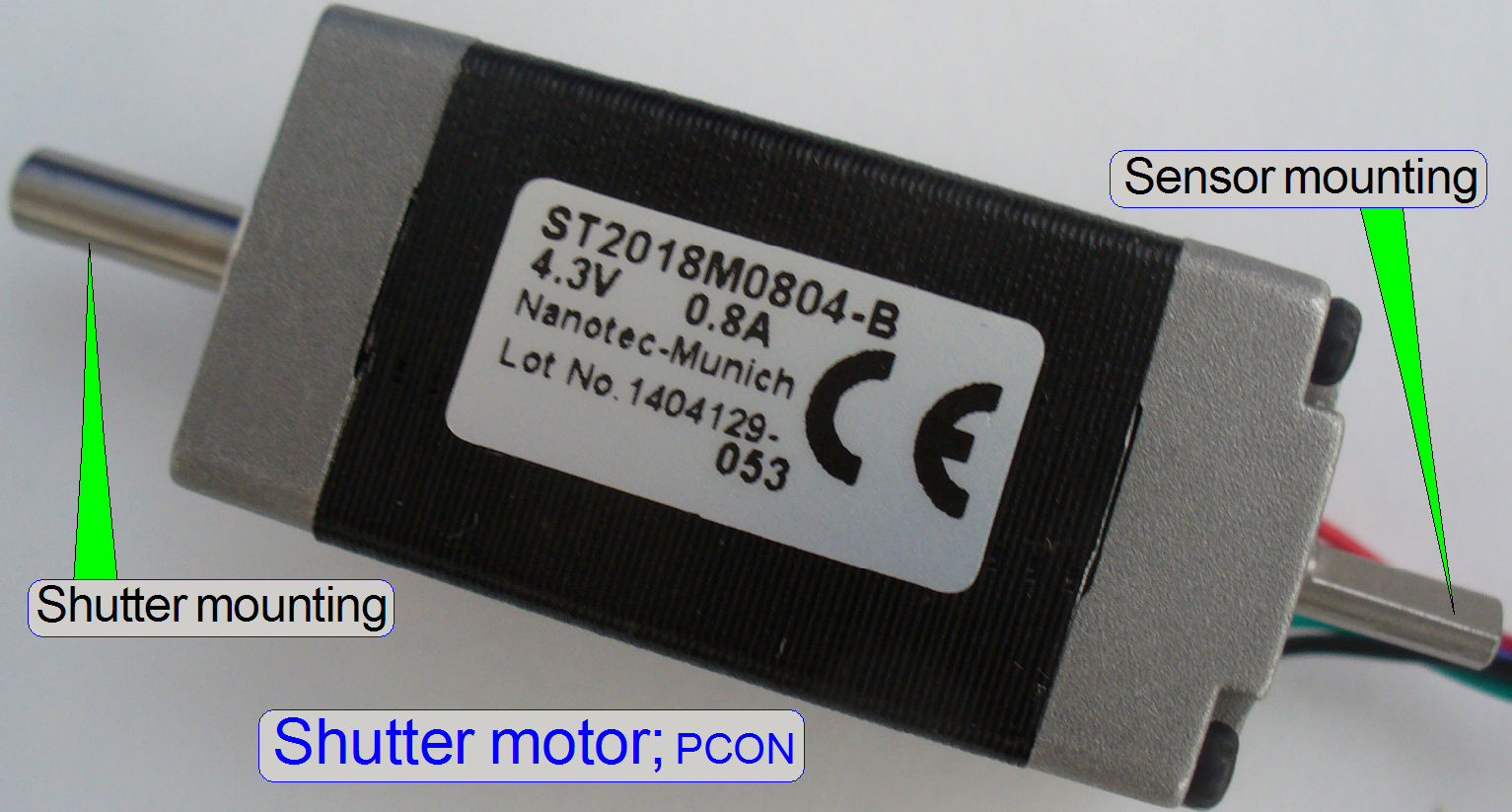 Type:� ST2018M0804-B
Power:����� 4.3V���������� 0.8A
Resolution (full
steps):������ 200 steps / revolution
� The stepper motor
is used to rotate the mechanical shutter into the brightfield illumination path
and keeps so a condenser�s cover, during fluorescent scan sessions.
See also:������ �Motors� galery�
Shutter
motor control
Attention
 The PCB�s
construction of the �Liquid feeder control� and the �Shutter control� is
identical, but they have different addresses!
The PCB�s
construction of the �Liquid feeder control� and the �Shutter control� is
identical, but they have different addresses!
� From outside, the control units are
undistinguishable!
Address of �Liquid feeder control� ������ = ����� 13
Address of �Shutter control� ����������������� =������ 14
See also �Addresses� and �Address assigning tool�
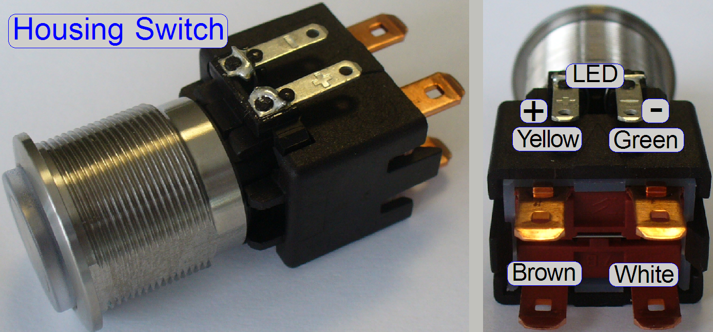 The Housing Switch
puts the power supply into running mode if the pins �Brown� and �White� are
shorted.
The Housing Switch
puts the power supply into running mode if the pins �Brown� and �White� are
shorted.
� The voltage is
about 15V- DC.
� The polarity of
the cable connectors is unimportant.
The LED is driven by the 12V- output of the power supply TDK-Lambda.
� The polarity is important!
See also:������ �Housing switch�
� 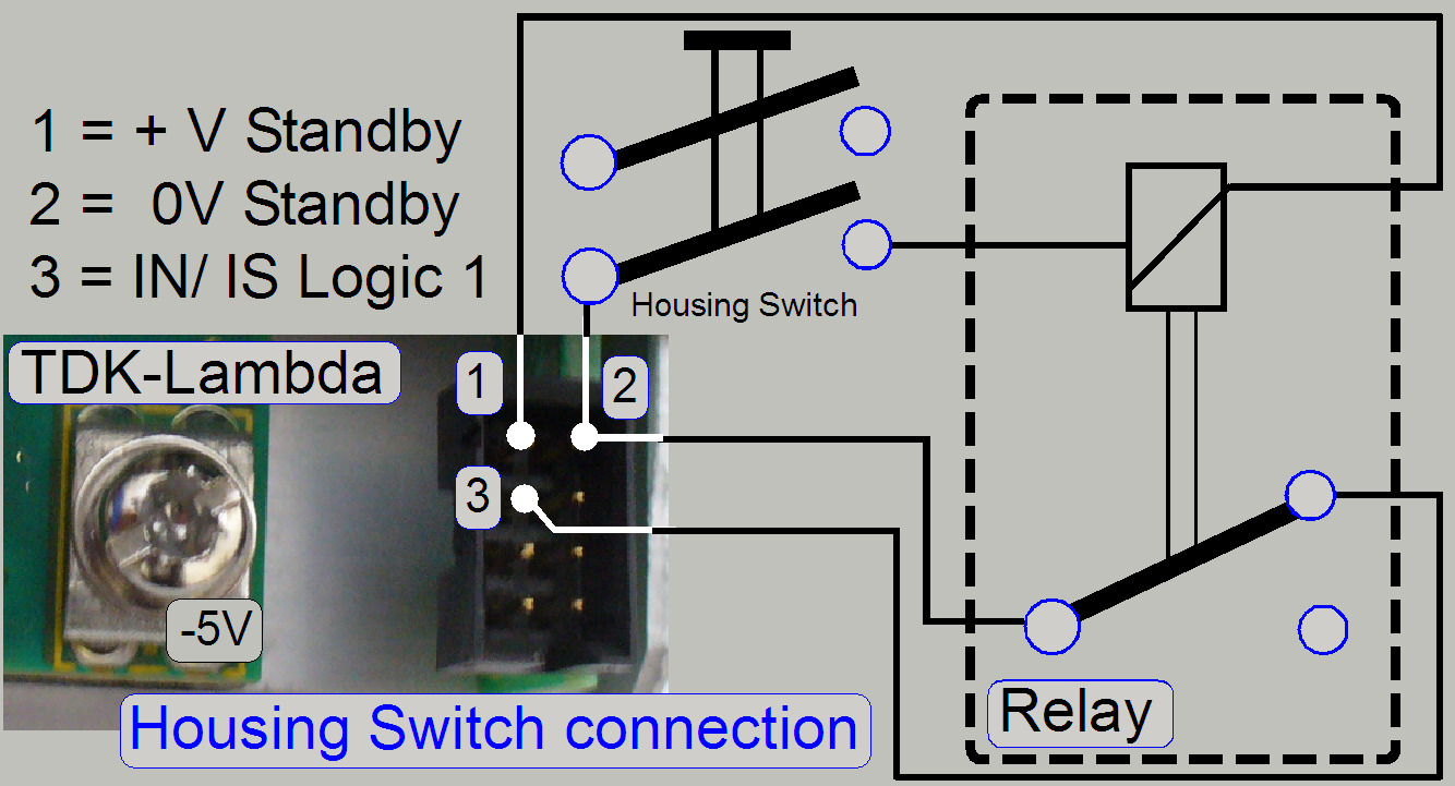 The relay is used to
invert the Housing Switch�s action!
The relay is used to
invert the Housing Switch�s action!
� 3 = open:������������������ Power is supplied
� 2 and 3 short:���������� Standby (power off state)
Trouble
shooting
If the standby connector is disconnected from the Housing Switch�s logic
and the power is supplied to the TDK-lambda, the power supply should run
continuously and all output voltages should be present!�
 The logo is
supplied by the output �
The logo is
supplied by the output �
� Check the power
path via the service program, if required
|
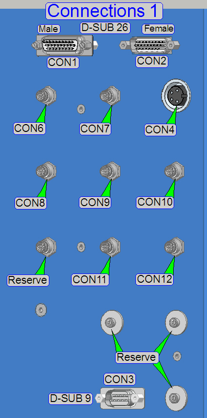
Connection; CON1 |
Connector |
Identifier |
Pins |
||
|
Sensors and illuminations |
CF01 |
+ |
- |
Signal |
|
|
Preview BF illumination |
CF01A |
10 |
11 |
|
|
|
Barcode illumination |
CF01B |
12 |
13 |
|
|
|
Preview DF illumination |
CF01C |
14 |
15 |
|
|
|
Preview DF illumination |
CF01D |
16 |
17 |
|
|
|
Tray sensor |
CF01E |
3 |
1 |
2 |
|
|
Slide sensor |
CF01F |
6 |
4 |
5 |
|
|
CON1:������ D-SUB 26p male ����������������������� Sensors,
illumination |
||||
|
Pin |
Function |
Wire color |
Type |
|
|
1 |
HAL1 (GND) slide |
YELLOW |
0,25 |
|
|
2 |
HAL1 (H1) slide |
|
0,25 |
|
|
3 |
HAL1 (VCC) slide |
RED |
0,25 |
|
|
4 |
HAL2 (GND) tray |
YELLOW |
0,25 |
|
|
5 |
HAL2 (H2) tray |
|
0,25 |
|
|
6 |
HAL2 (VCC) tray |
RED |
0,25 |
|
|
7 |
x |
x |
x |
|
|
8 |
x |
x |
x |
|
|
9 |
x |
x |
x |
|
|
10 |
BFP (LED5 +24V) |
YELLOW |
0,25 |
|
|
11 |
BFP (LED5 -24V) |
RED |
0,25 |
|
|
12 |
BC (LED4 +24V) |
YELLOW |
0,25 |
|
|
13 |
BC (LED4 -24V) |
|
0,25 |
|
|
14 |
DFP (DLD1 +24V) |
YELLOW |
0,25 |
|
|
15 |
DFP (DLD1 -24V) |
BLACK |
0,25 |
|
|
16 |
DFP (DLD1 -24V) |
YELLOW |
0,25 |
|
|
17 |
DFP (DLD1 +24V) |
BLACK |
0,25 |
|
|
18 |
x |
x |
x |
|
|
19 |
TEMP (RESERVE) |
BROWN |
0,25 |
|
|
20 |
TEMP (RESERVE) |
BROWN |
0,25 |
|
|
21 |
TEMP (RESERVE) |
WHITE |
0,25 |
|
|
22 |
TEMP (RESERVE) |
WHITE |
0,25 |
|
|
23 |
TEMP (RESERVE) |
BLUE |
0,25 |
|
|
24 |
TEMP (RESERVE) |
BLUE |
0,25 |
|
|
25 |
TEMP (RESERVE) |
BLACK |
0,25 |
|
|
26 |
TEMP (RESERVE) |
BLACK |
0,25 |
|
|
CON2:������ D-SUB 26p� female ����������������������� PCO.edge
Power |
||||
|
Pin |
Function |
Wire color |
Type |
|
|
1 |
+12V PCO |
RED |
0,75 |
|
|
2 |
+12V PCO |
RED |
0,75 |
|
|
3 |
x |
x |
x |
|
|
4 |
-12V PCO |
BLUE |
0,75 |
|
|
5 |
-12V PCO |
BLUE |
0,75 |
|
|
6 |
x |
x |
x |
|
|
7 |
x |
x |
x |
|
|
8 |
x |
x |
x |
|
|
9 |
x |
x |
x |
|
|
10 |
+12V PCO |
RED |
0,75 |
|
|
11 |
+12V PCO |
RED |
0,75 |
|
|
12 |
x |
x |
x |
|
|
13 |
-12V PCO |
BLUE |
0,75 |
|
|
14 |
-12V PCO |
BLUE |
0,75 |
|
|
15 |
x |
x |
x |
|
|
16 |
x |
x |
x |
|
|
17 |
x |
x |
x |
|
|
18 |
x |
x |
x |
|
|
19 |
x |
x |
x |
|
|
20 |
x |
x |
x |
|
|
21 |
x |
x |
x |
|
|
22 |
x |
x |
x |
|
|
23 |
x |
x |
x |
|
|
24 |
x |
x |
x |
|
|
25 |
x |
x |
x |
|
|
26 |
x |
x |
x |
|
|
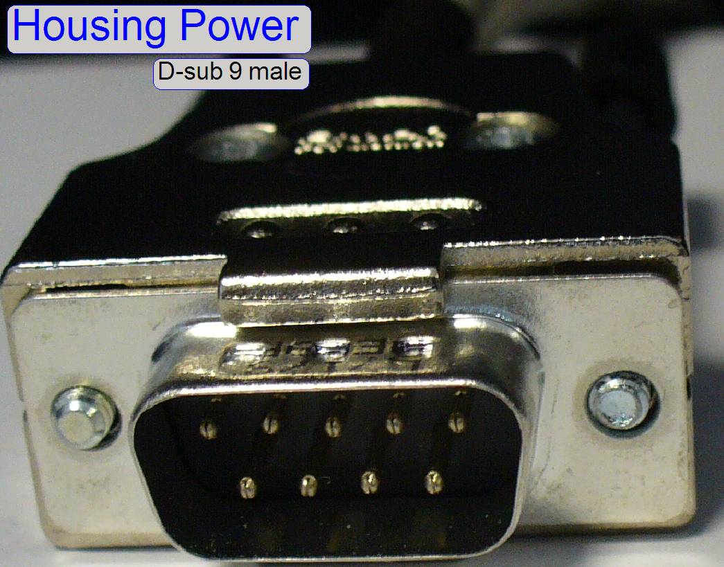
CON3:������ D-SUB 9p female ����������������������� Housing |
||||
|
Pin |
Function |
Wire color |
Type |
|
|
1 |
12V Relay A2(1) |
YELLOW |
0,25 |
|
|
2 |
PWS J3-PIN2 (-12V) |
BLACK |
0,25 |
|
|
3 |
x |
x |
x |
|
|
4 |
LED (switch) +12V |
RED |
0,75 |
|
|
5 |
LED (switch) -12V |
BLUE |
0,75 |
|
|
6 |
LOGO +12V |
RED |
0,75 |
|
|
7 |
||||
|
8 |
LOGO -12V |
BLUE |
0,75 |
|
|
9 |
||||
|
CON4:������ 4P
Binder� female ����������������������� Lumencor Power |
||||
|
Pin |
Function |
Wire color |
Type |
|
|
1 |
+24V |
RED |
0,75 |
|
|
2 |
+24V |
RED |
0,75 |
|
|
3 |
-24V |
BLUE |
0,75 |
|
|
4 |
-24V |
BLUE |
0,75 |
|
|
CON5:������ 5P
Binder female ����������������������� Confocal
Power |
||||
|
Pin |
Function |
Wire color |
Type |
|
|
1 |
+12V |
BLACK |
1,5 |
|
|
2 |
+12V |
BLUE |
1,5 |
|
|
3 |
GND |
GREEN-YELL. |
1,5 |
|
|
4 |
-12V |
BROWN |
1,5 |
|
|
5 |
-12V |
WHITE |
1,5 |
|
|
CON6:������ 4P
Binder male ����������������������� Mechanical
Shutter |
||||
|
Pin |
Function |
Wire color |
Type |
|
|
1 |
+24V |
BROWN |
0,25 |
|
|
2 |
-24V |
WHITE |
0,25 |
|
|
3 |
LIN |
BLACK |
0,25 |
|
|
4 |
LIN |
BLUE |
0,25 |
|
|
CON7:������ 4P
Binder male ����������������������� Tray
Loader |
||||
|
Pin |
Function |
Wire color |
Type |
|
|
1 |
+24V |
BROWN |
0,25 |
|
|
2 |
-24V |
WHITE |
0,25 |
|
|
3 |
LIN |
BLACK |
0,25 |
|
|
4 |
LIN |
BLUE |
0,25 |
|
|
CON8:������ 4P
Binder male ����������� Immersion liquid feeder |
||||
|
Pin |
Function |
Wire color |
Type |
|
|
1 |
+24V |
BROWN |
0,25 |
|
|
2 |
-24V |
WHITE |
0,25 |
|
|
3 |
LIN |
BLACK |
0,25 |
|
|
4 |
LIN |
BLUE |
0,25 |
|
|
CON9:������ 4P
Binder male ����������������������� Slide
Loader |
||||
|
Pin |
Function |
Wire color |
Type |
|
|
1 |
+24V |
BROWN |
0,25 |
|
|
2 |
-24V |
WHITE |
0,25 |
|
|
3 |
LIN |
BLACK |
0,25 |
|
|
4 |
LIN |
BLUE |
0,25 |
|
|
CON10:��� 4P
Binder male ����������������������� RGB BF
illumination |
||||
|
Pin |
Function |
Wire color |
Type |
|
|
1 |
+24V |
BROWN |
0,25 |
|
|
2 |
-24V |
WHITE |
0,25 |
|
|
3 |
LIN |
BLACK |
0,25 |
|
|
4 |
LIN |
BLUE |
0,25 |
|
|
CON11:��� 4P
Binder male ����������������������� Objective changer unit |
||||
|
Pin |
Function |
Wire color |
Type |
|
|
1 |
+24V |
BROWN |
0,25 |
|
|
2 |
-24V |
WHITE |
0,25 |
|
|
3 |
LIN |
BLACK |
0,25 |
|
|
4 |
LIN |
BLUE |
0,25 |
|
|
CON12:��� 2P
Binder male ����������������������� BLUM
Servo Door Opener |
||||
|
Pin |
Function |
Wire color |
Type |
|
|
1 |
+24V |
RED |
1,5 |
|
|
2 |
-24V |
BLUE |
1,5 |
|
|
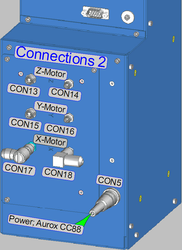
CON13:��� 4P
Binder female ����������������������� Z-Motor |
||||
|
Pin |
Function |
Wire color |
Type |
|
|
1 |
MOD2-J2-1 (OA1) |
BROWN |
0,25 |
|
|
2 |
MOD2-J2-2 (OA2) |
WHITE |
0,25 |
|
|
3 |
MOD2-J2-3 (OB1) |
BLACK |
0,25 |
|
|
4 |
MOD2-J2-4 (OB2) |
BLUE |
0,25 |
|
|
CON14:��� 4P
Binder male ����������������������� Z-Motor |
|||||
|
Pin |
Function |
Wire color |
Type |
||
|
1 |
MOD2-J1-1 (VCC) |
BROWN |
0,25 |
||
|
2 |
MOD2-J1-2 (IMP1) |
WHITE |
0,25 |
||
|
3 |
MOD2-J1-3 (IMP2) |
BLACK |
0,25 |
||
|
4 |
MOD2-J1-4 (GND) |
BLUE |
0,25 |
||
|
|||||
|
CON15:����� 4P
Binder female ����������������������� Y-Motor |
||||
|
Pin |
Function |
Wire color |
Type |
|
|
1 |
MOD2-J2-1 (OA1) |
BROWN |
0,25 |
|
|
2 |
MOD2-J2-2 (OA2) |
WHITE |
0,25 |
|
|
3 |
MOD2-J2-3 (OB1) |
BLACK |
0,25 |
|
|
4 |
MOD2-J2-4 (OB2) |
BLUE |
0,25 |
|
|
CON16:��� 4P
Binder male ����������������������� Y-Motor |
||||
|
Pin |
Function |
Wire color |
Type |
|
|
1 |
MOD2-J1-1 (VCC) |
BROWN |
0,25 |
|
|
2 |
MOD2-J1-2 (IMP1) |
WHITE |
0,25 |
|
|
3 |
MOD2-J1-3 (IMP2) |
BLACK |
0,25 |
|
|
4 |
MOD2-J1-4 (GND) |
BLUE |
0,25 |
|
|
CON17:��� 4P
Binder female ����������������������� X-Motor |
||||
|
Pin |
Function |
Wire color |
Type |
|
|
1 |
MOD2-J2-1 (OA1) |
BROWN |
0,25 |
|
|
2 |
MOD2-J2-2 (OA2) |
WHITE |
0,25 |
|
|
3 |
MOD2-J2-3 (OB1) |
BLACK |
0,25 |
|
|
4 |
MOD2-J2-4 (OB2) |
BLUE |
0,25 |
|
|
CON18:��� 4P
Binder male ����������������������� X-Motor |
||||
|
Pin |
Function |
Wire color |
Type |
|
|
1 |
MOD2-J1-1 (VCC) |
BROWN |
0,25 |
|
|
2 |
MOD2-J1-2 (IMP1) |
WHITE |
0,25 |
|
|
3 |
MOD2-J1-3 (IMP2) |
BLACK |
0,25 |
|
|
4 |
MOD2-J1-4 (GND) |
BLUE |
0,25 |
|