Objective Changer; PCON
For technicians and
partly for sales managers!
These instructions describe the
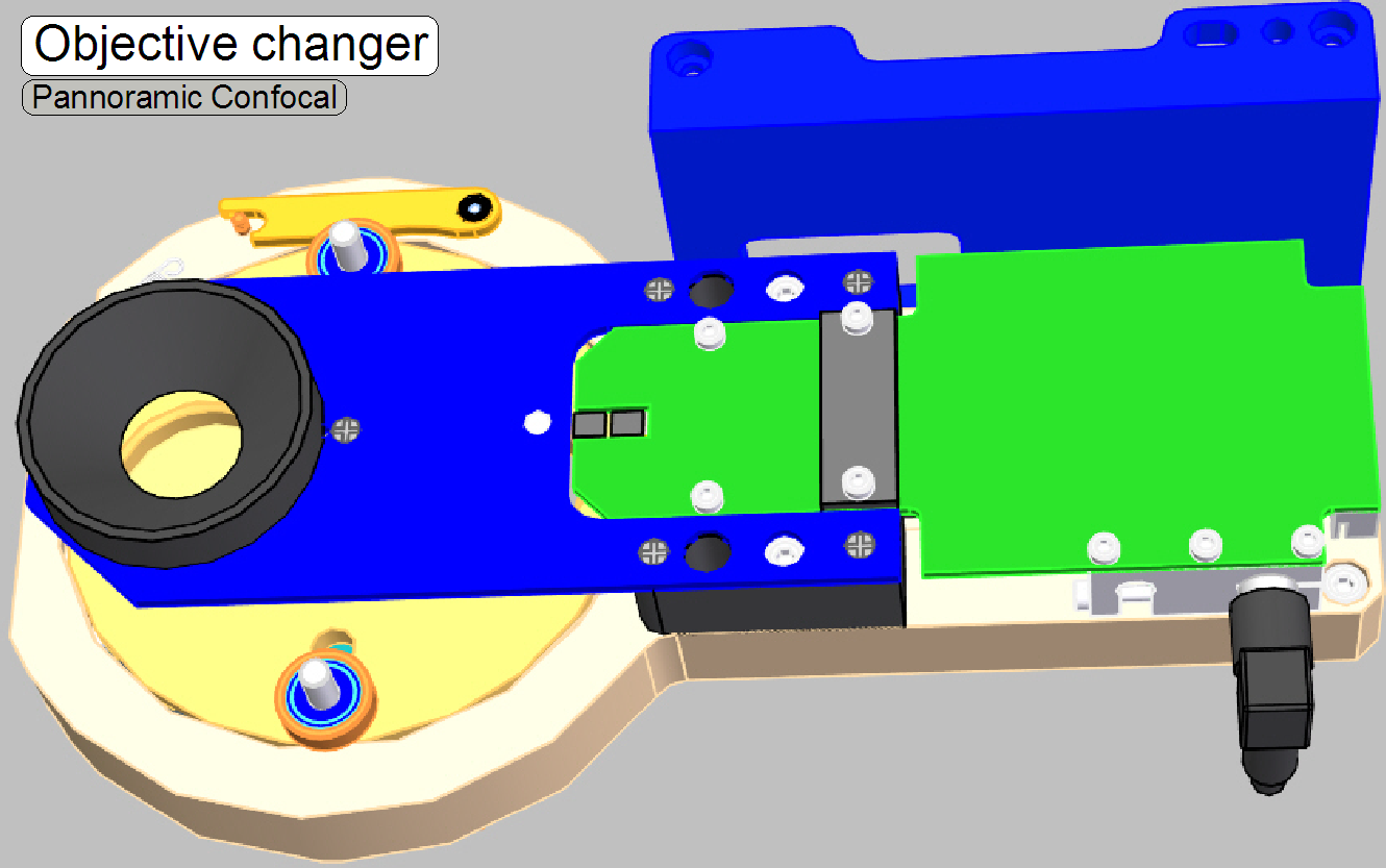
procedures to install and adjust the Objective Changer of the scanner
Pannoramic Confocal. The Objective Changer is a separate unit in the optical
path. To help resolve problems with the Objective Changer a hardware
description of the implemented components and adjustment procedures are added.
Software relevant settings are based
on the software version 1.19.
· The unit is derived from the Objective Changer Unit of
the scanner P250.

Contents
- General
- Configure
- Working principle
- Change the objective
(Software)
- Use the service
program
- Components,
construction
- Dismount
- Assembling
- Adjustments
- Setup
implemented objectives
- Align
the Objective position

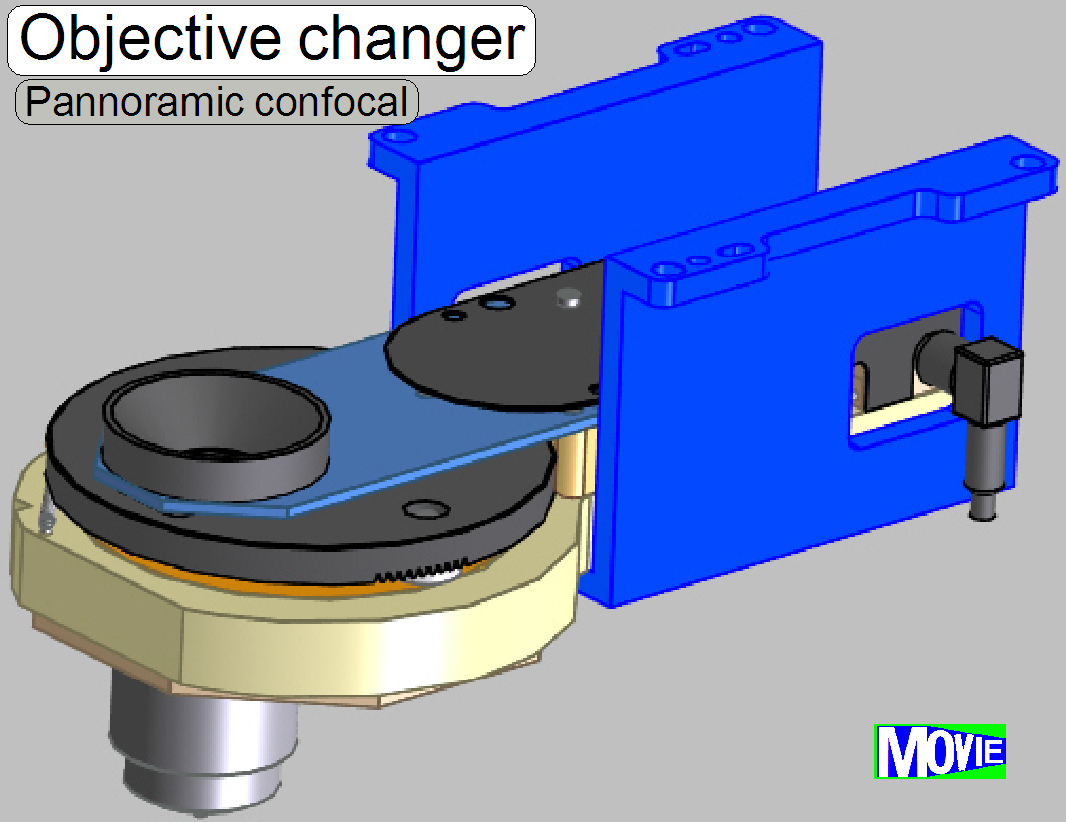
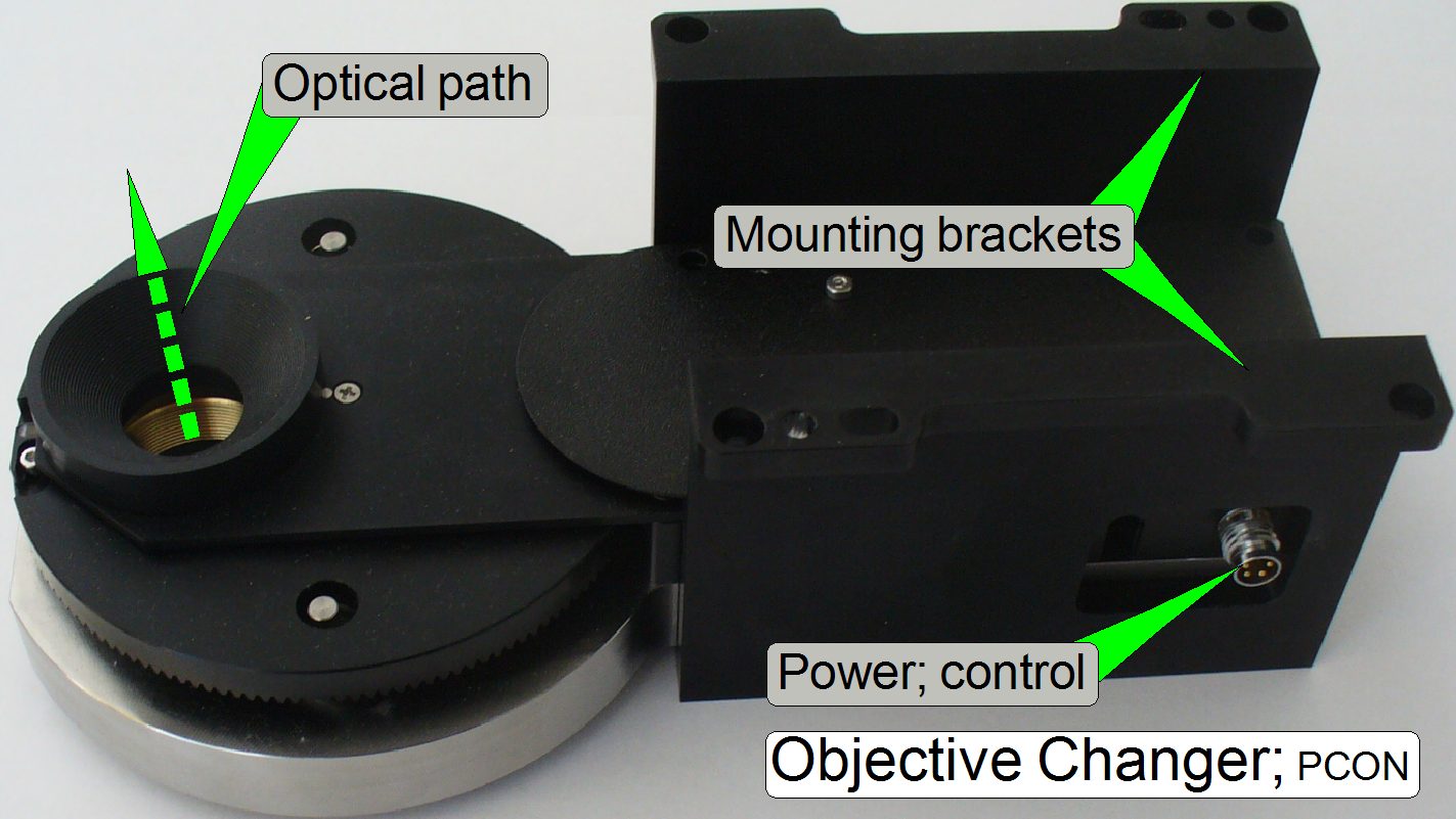
The Objective Changer unit (OC) is mounted into the optical path separately and allows the consecutive
use of two, preinstalled objectives. The selection or changing of the objective
is initiated by software before a slide scan session is started and may be
altered between 2 slide scan procedures. The movement of the objective holder
disc is executed via a DC-motor and the position is sensed via Hall sensors.
Each objective position has a separate hall sensor, so the software knows
always which objective is actually in use. To guarantees the proper position of
the objective in the light path, the final objective position is fixed in the
optical path via a form-fit mechanism.
 The unit was
developed for the use of objectives of the following types:
The unit was
developed for the use of objectives of the following types:
Plan-APOCHROMAT
20x/0.8 and C-APOCHROMAT 40x/1.2 W Corr M27
If the mechanical dimensions
do not exceed the size of the C-APOCHROMAT 40x/1.2W type objective, the
mechanical mounting is identical and the focus distance of the objective to the
tissue is not closer then 0.25mm, other kind of objectives can be used also but
it is strongly not recommended!
Important
·
Always
check with 3DHISTECH first if a different objective should be used!
Automatic scan
In the slide scan table of
the scan program “SlideScanner.exe” you can assign the objective with which the
slide should be scanned. In other words, the objective can be changed any time
between two slide scanning procedures. If the slide scan table does not contain
information about the objective, the scan procedure will be done with the
actually selected objective.
Manual scan
The objective can be changed any time, before
the scan procedure is started.
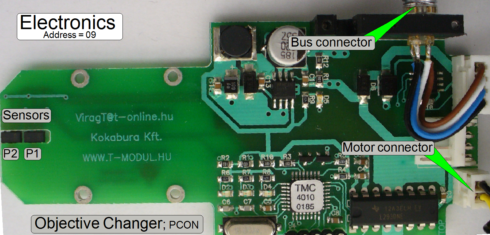
The bus connector supplies power
and control information for the Objective Changer via the cable CON-12.
The exchange of the Objective Changer is
possible:
- If the DC motor or the electronics of the
Objective Changer unit is faulty.
- If the shape of any part is deformed or a part is
broken.
- If the focus unit or the Objective Changer has any fault and you are unable to
fix it.
Requirements
- Service program for slide scanners (SlideScannerService.exe) with
actual license file
- Slide scanner (version 1.19 or higher) and Slide
scanner Viewer software (SlideScanner.exe, MView.exe) with actual dongle
or license
- 1.5, 2.5, 3 and
- Hardware and
construction knowledge of the scanner Panoramic Confocal
 Attention: Do not mix the versions of SlideScanner.exe and
SlideScannerService.exe! Always use these programs with the same version
number. Otherwise the SlideScannerService.exe program could produce unwanted
results and SlideScanner.exe does not work correctly or even freeze!
Attention: Do not mix the versions of SlideScanner.exe and
SlideScannerService.exe! Always use these programs with the same version
number. Otherwise the SlideScannerService.exe program could produce unwanted
results and SlideScanner.exe does not work correctly or even freeze!
Main differences to the
Objective Changer Unit of the P250
·
 The unit is
separated from the focus unit and is mounted to the tilting table by two
brackets.
The unit is
separated from the focus unit and is mounted to the tilting table by two
brackets.
·
Bus extender cable is removed
·
Mechanical mounting of parts is modified.

Working distances of
objectives
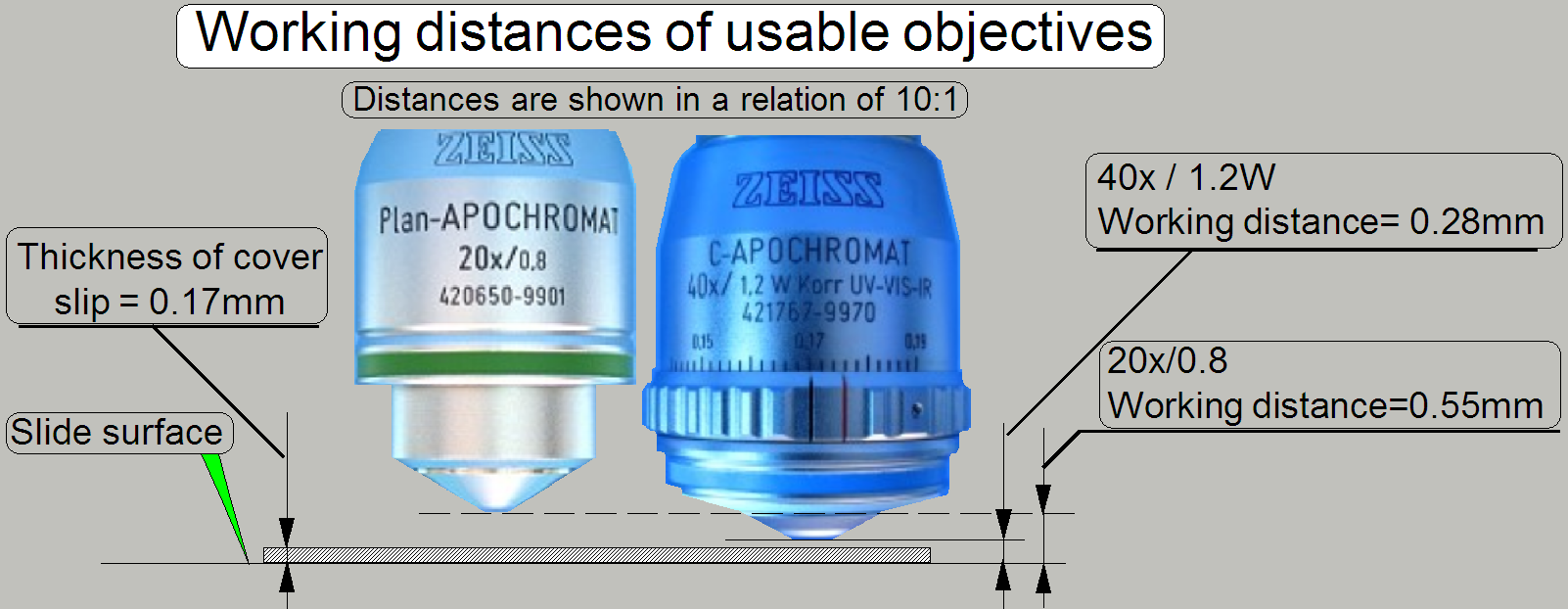 As you can see,
the gaps between cover slip and objective are very small, especially if the
objective C-APOCHROMAT 40x/1.2 W Corr M27
is used.
As you can see,
the gaps between cover slip and objective are very small, especially if the
objective C-APOCHROMAT 40x/1.2 W Corr M27
is used.
Because both objectives can
be used without adjustment of the objective position after exchange, the
previously developed focus unit (the focus unit for SCAN,
 On the scale of
the 40x objective, the thickness of the cover slip should be selected.
On the scale of
the 40x objective, the thickness of the cover slip should be selected.
- If the real thickness of the cover slip
differs from the selected or adjusted value, the quality of the scanned
FOV may be reduced!
Objective position
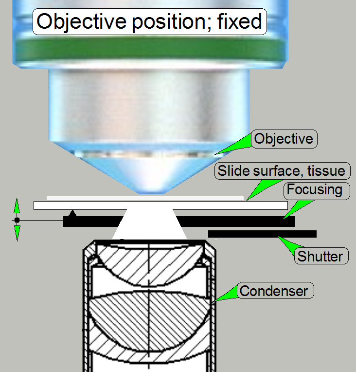 In Pannoramic type
scanners the objective is mounted into the middle of the focus range, offered
by the movement limits of the focus pin during focusing.
In Pannoramic type
scanners the objective is mounted into the middle of the focus range, offered
by the movement limits of the focus pin during focusing.
- It is very important, that the objective
position is adjusted well; otherwise, if the objective position does not
match the focus range, offered by the focus pin movement range, a focused
camera image can never be produced!
- Because the slide thickness can vary from
0.95 to
- See also “Adjust
the objective position”.
Configure the Objective Changer unit
Since the software version 1.15 the units of the scanner are configured
in the file “MicroscopeConfiguration.ini”, section [Microscope].
· The path
of the file MicroscopeConfiguration.ini, in the software version with the
operating system Windows® 7 is:
C:\ProgramData\3DHISTECH\SlideScanner\MicroscopeConfiguration.ini
[Microscope]
 SerialNumber=PCON_xxx
MicroscopeType=3DMic10
MicroscopeSubtype=Confocal
ScanCameraType=
PreviewCameraType=CVrmc_m8_pPro
BarcodeReaderType=PreviewCamera
LoaderType=SL_1Mag_12Slide_Sensor_Horizontal2
CameraChangerType=CC_none
ReflectorTurretType=RT_None
BrightfieldLightSourceType=RGBLedLight
ObjectiveChangerType=OC_2Pos
ObjectGuideXYZType=OGXYZ_FLASH4
FlashUnitType=NoFlashUnit
NDFilterType=NDType_None
PreviewLightType=PreviewLightUnitType_Type2
ShutterMotorType=Shutter_Motor
PowerSwitchBoardType=PowerSwitchBoard_Type1
ConfocalUnitType=ConfocalUnitType_Aurox
WaterFeederType=WaterFeeder_Type1
Software handling
Following
sequence describes the steps, done by software, to change the objective!
·
Please
do logically the same steps (depending on the task), if you are working with
the service program
1)
Memorize the actual position of the X- and Y-stage.
2)
Move the X- and Y-stage to a save position (collision
with the slide or the specimen holder must not be possible).
3)
Start the Objective Changer DC-motor in forward
direction.
4)
Watch the sensor states “Sensor
5)
Wait 500ms
6)
Move the X- and Y-stage return to the memorized
position.
7)
If live view: actualize the focus position (by using
the Z-offset, defined in “MicroscopeSettings.ini”).
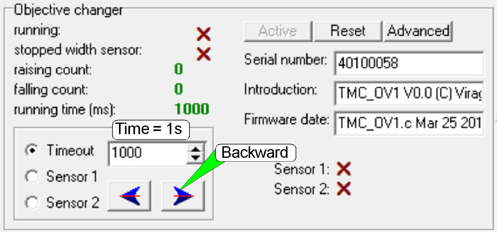
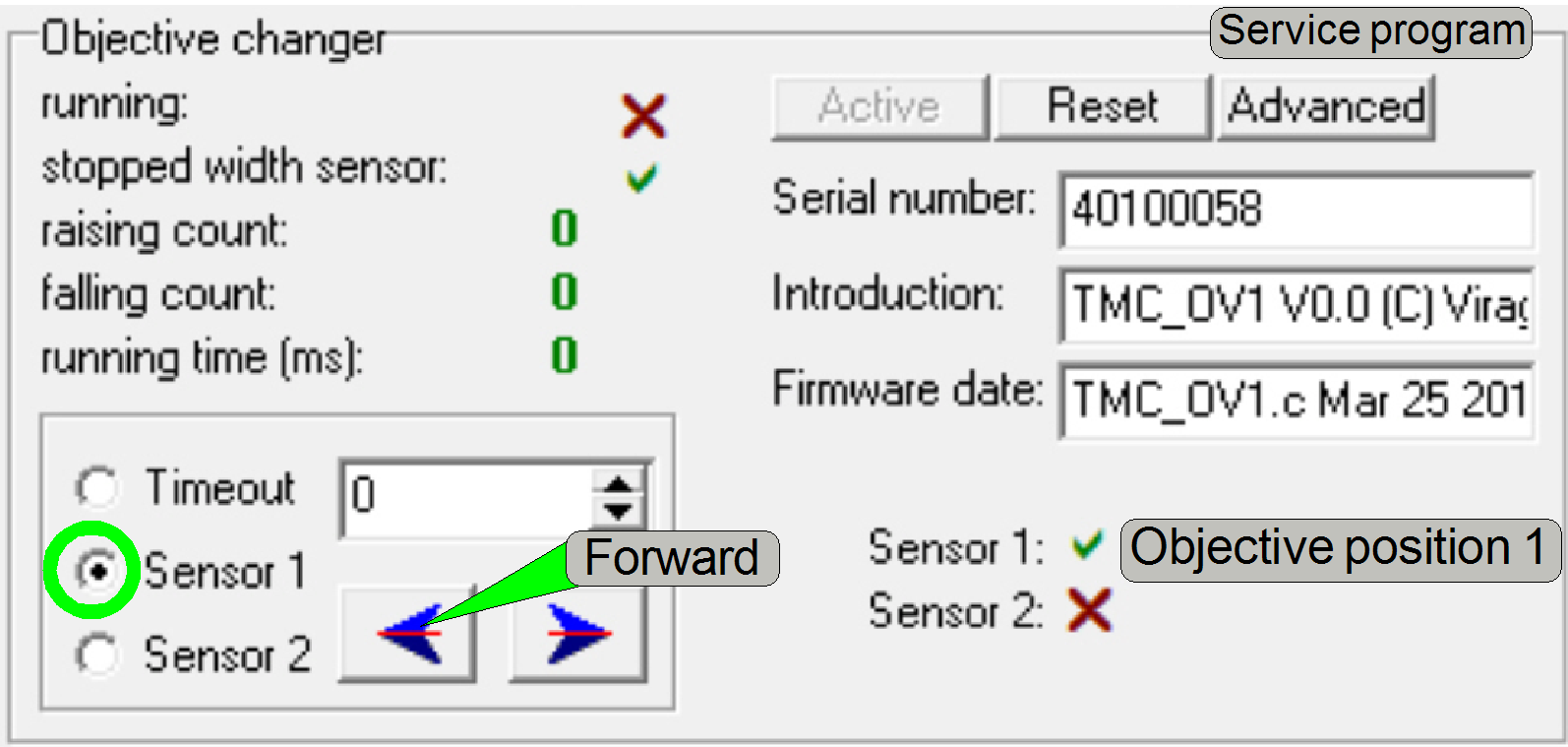
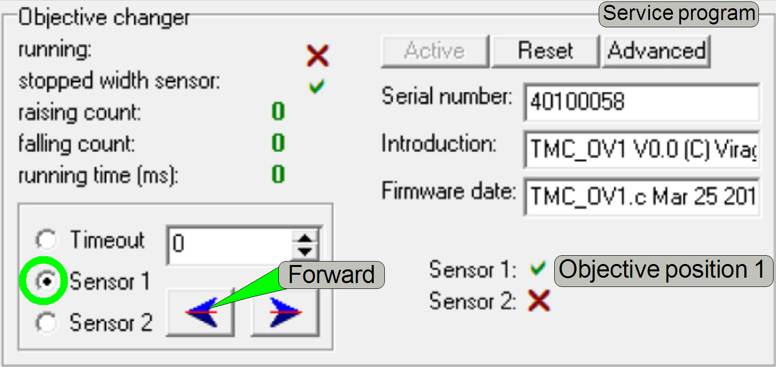
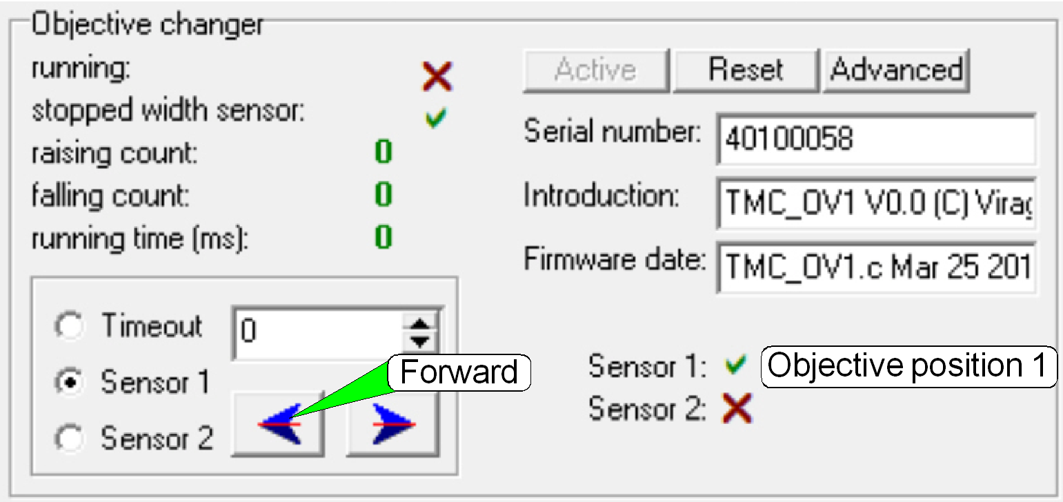 The tools of the Objective
Changer in the service program are shown on the right.
The tools of the Objective
Changer in the service program are shown on the right.
Check the Objective position 1
1.
With the service program set the Y-stage to Home1,2.
2.
Set the X-stage to Home1,2.
3.
In the tab “Objective Changer”, select the sensor 1
and press the button “Forward”; the 20x objective should move into the working
position of the Objective Changer unit, in the specified movement direction and
the form-fit mechanics should snap in correctly.
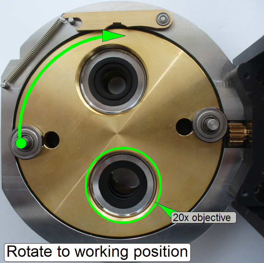
Set the Objective position 1
1.
If the working position 1 is not correct after the
check, remove the entire
Objective Changer unit.
2.
Connect the power and control cable
3.
In the service program, select “Sensor
4.
If now the 40x objective is in the working position, remove the Transport Disc.
5.
Rotate the Objective Disc by a ½ revolution so,
that the 20x objective stays in the optical path.
6.
Mount the Transport Disc
ant the PGB.
7.
Doe the check of the working position with both
objective positions several times; hereby, the Objective Changer unit should be
hold in its working position!
8.
Mount the PCB cover.
9.
Mount the Objective Changer.
See also: “Service
program” and “Objective
Changer”
 The objective
change procedure is initiated by the user, if the manual scan mode is selected,
or by software, if the automatic scan procedure is in progress. In both scan
modes, the objective change may be executed only between 2 slide scan sessions,
if momentarily a scan procedure is not in progress.
The objective
change procedure is initiated by the user, if the manual scan mode is selected,
or by software, if the automatic scan procedure is in progress. In both scan
modes, the objective change may be executed only between 2 slide scan sessions,
if momentarily a scan procedure is not in progress.
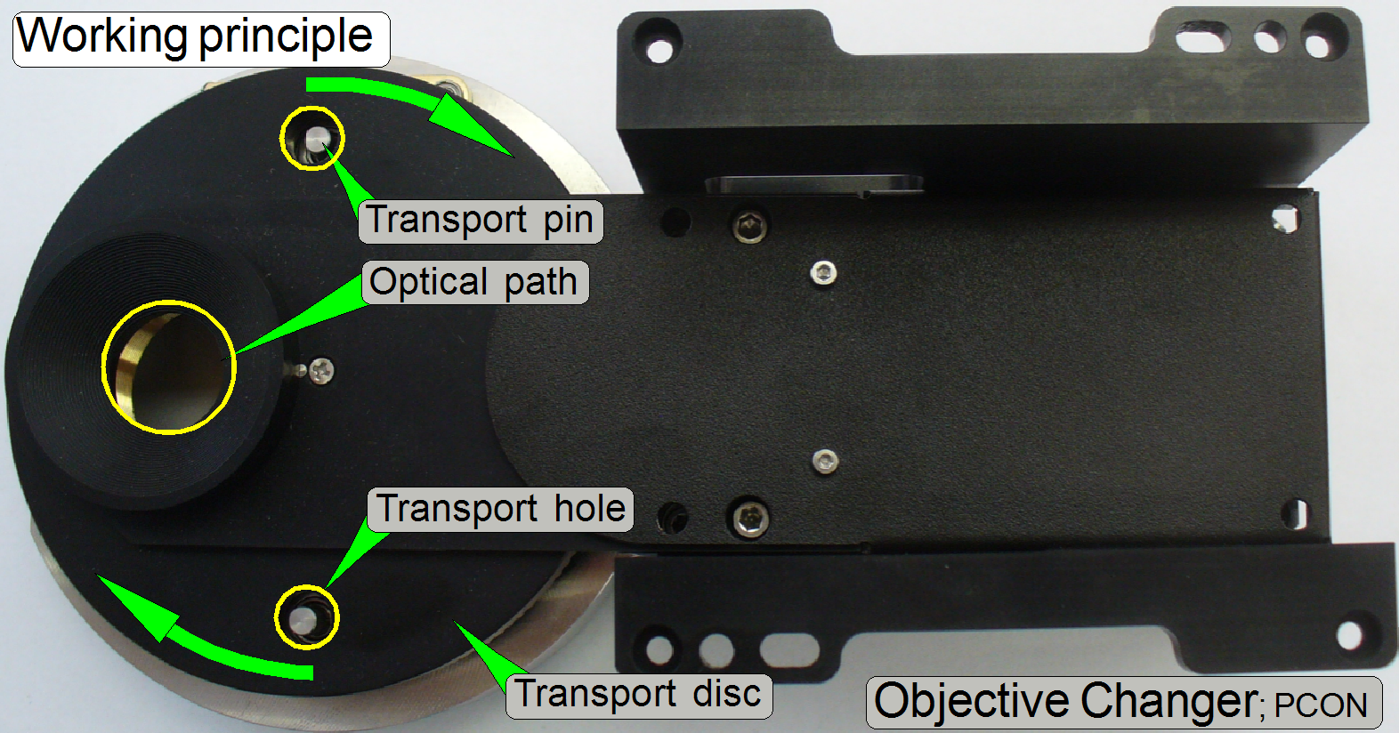
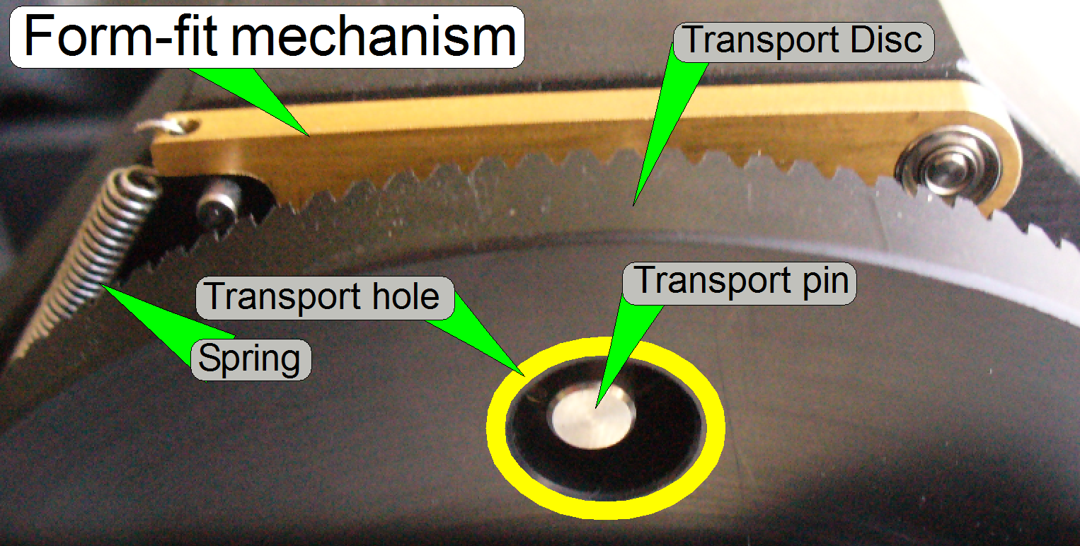
During the objective change
procedure, the Transport Disc is rotated by a DC motor; always in mathematical
positive direction, if we are looking onto the objectives.
The Transport Disc moves the
transport pins situated in the transport holes, by a half revolution.
Just before the working
position of the objective is reached, the DC motor will be switched off by the
appropriate sensor and the final movement into the exact working position (into
the optical axis), is done by the form-fit mechanism.
- The Transport Disc can be rotated manually,
but do it carefully!
- The unit does not need maintenance.
Watch video: “Change the objective” (P250)
Watch slide show: “OC_PCON”
 The geared ring of
the Transport Disc is driven by the gearwheel of a DC-motor gear.
The geared ring of
the Transport Disc is driven by the gearwheel of a DC-motor gear.
·
Together with the Transport Disc, the transport holes
will rotate also.
·
 The transport
pins, mounted on the Objective Disc and situated in the transport holes
rotating the Objective Disc.
The transport
pins, mounted on the Objective Disc and situated in the transport holes
rotating the Objective Disc.
·
By rotating the Objective Disc exactly by a ½
revolution, the other objective position will be moved into the working
position.
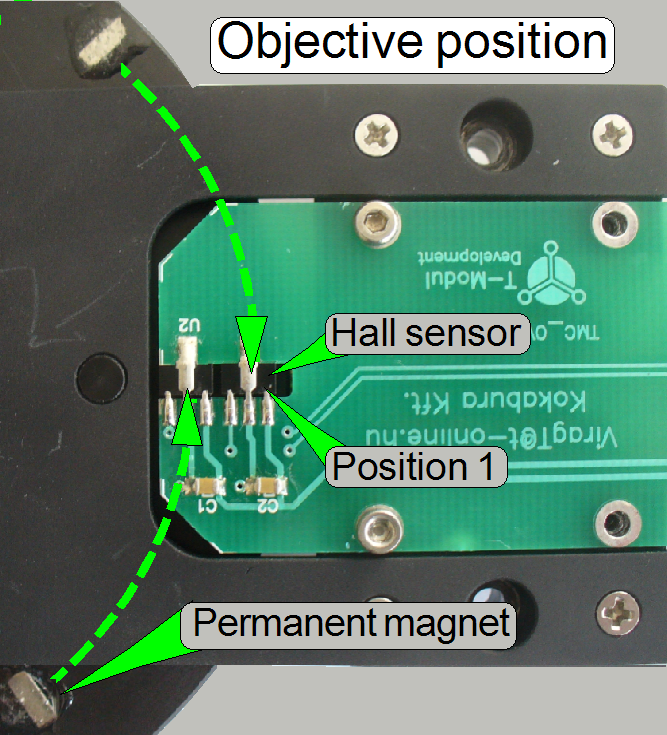 If the permanent
magnet, situated in the top part of the Transport Disc arrives to its
appropriate Hall sensor, the DC-motor stops driving the Transport Disc.
If the permanent
magnet, situated in the top part of the Transport Disc arrives to its
appropriate Hall sensor, the DC-motor stops driving the Transport Disc.
- Each objective (position) has its own
sensor and its own permanent magnet also; the positions are named as
“Objective position
- In the objective position 1 always the 20x
objective has to be mounted; in the objective position 2 the 40x objective
is situated.
- The objective positions 1 and 2 of the Objective
Disc are decided, if the Transport Disc will be mounted; see also: “Set the
objective position 1” and “Mount the Transport
Disc”
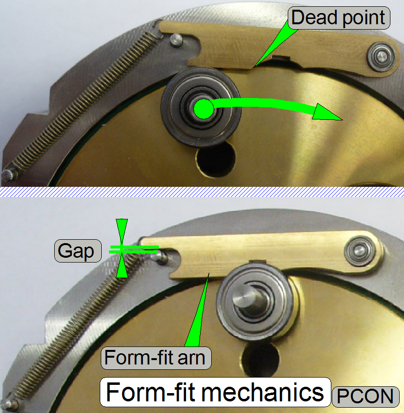
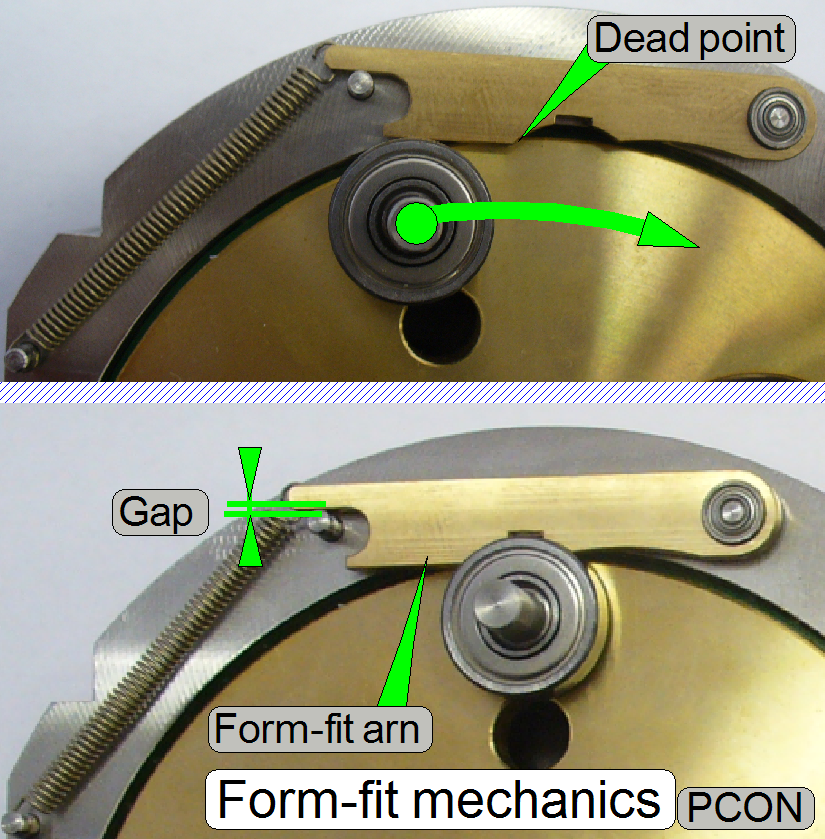 If the ball
bearing of the transport pin even crossed the dead point of the form-fit arm,
the permanent magnet arrived over the appropriate Hall sensor and the DC-motor stops driving the Transport Disc.
If the ball
bearing of the transport pin even crossed the dead point of the form-fit arm,
the permanent magnet arrived over the appropriate Hall sensor and the DC-motor stops driving the Transport Disc.
The form-fit arm, together
with the force of the spring presses the ball bearing of the transport pin into
the shape of the form-fit arm and the objective is correctly aligned into the
optical axis.
·
The position of the transport pin’s ball bearing in
relation to the dead point is critical for switching off the DC-motor.
·
The correct position will be found by adjusting the
permanent magnet position.
Watch video: “P250_Objective change”
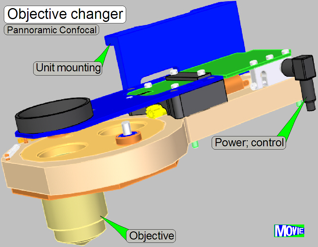
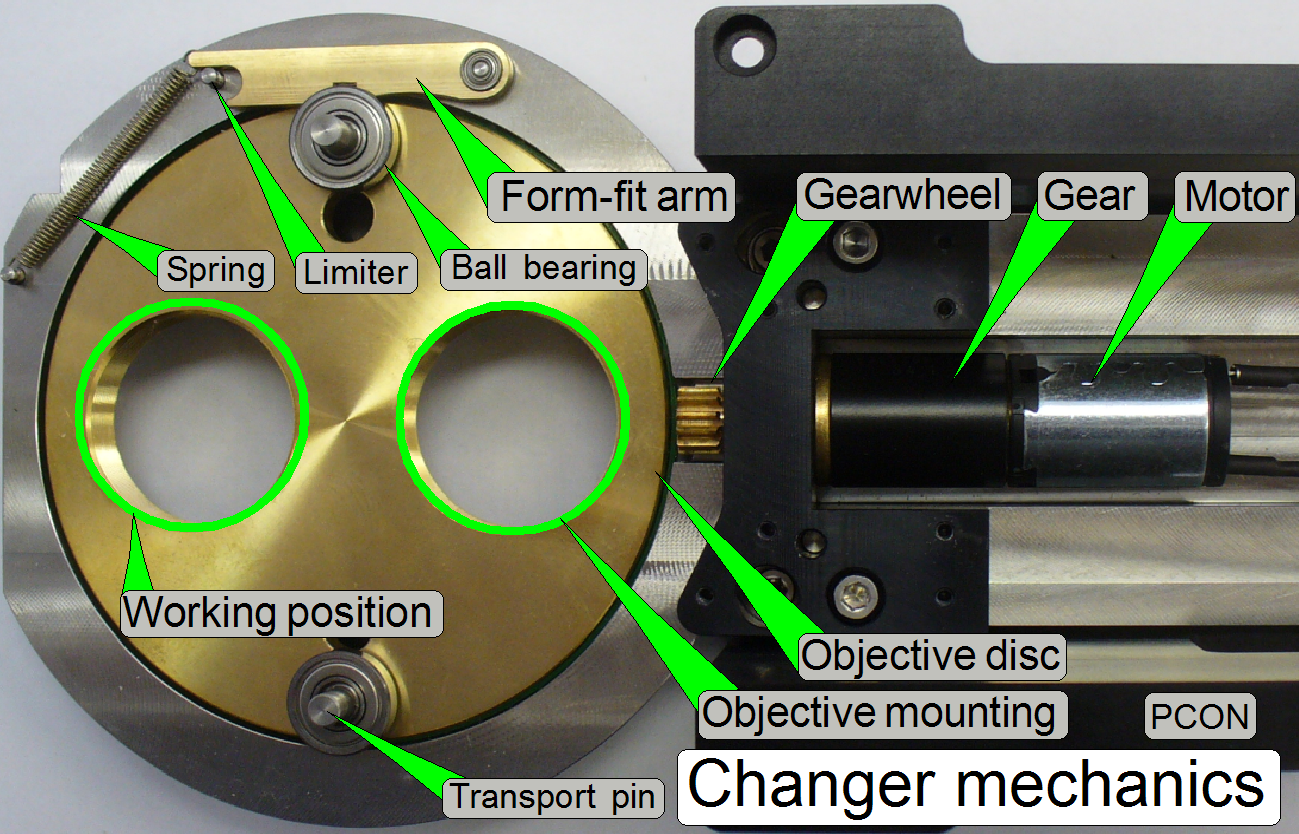
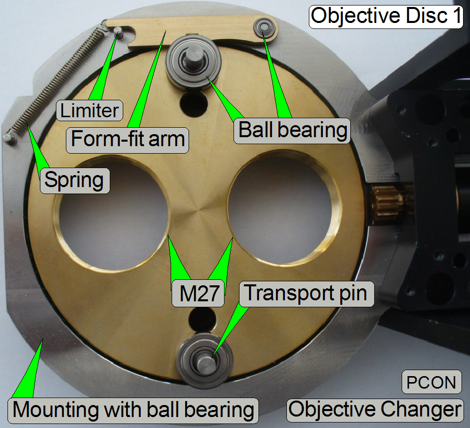
 The
Objective Changer consists of:
The
Objective Changer consists of:
·
Mounting brackets (holder)
·
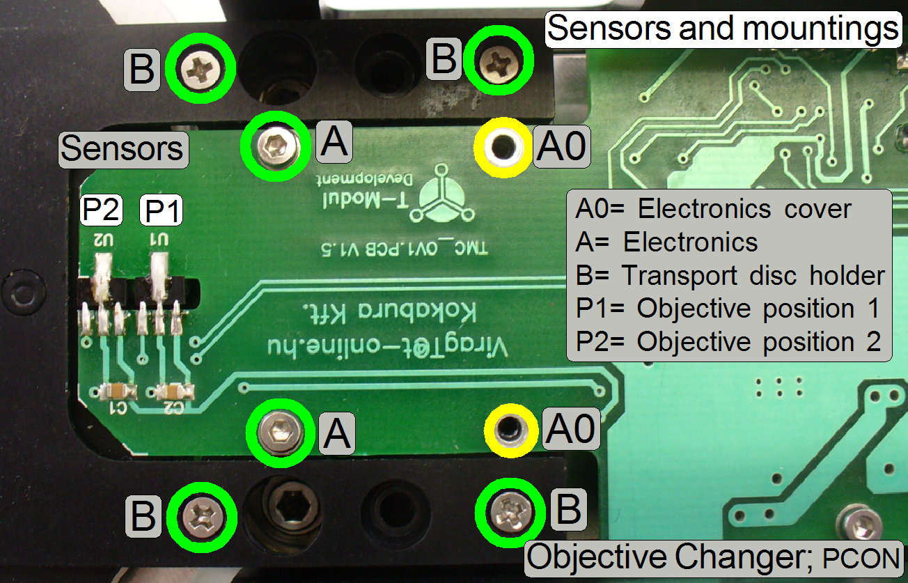
The drive unit with Transport Disc, DC motor and control electronics.
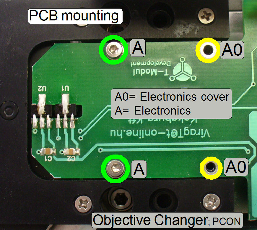
·
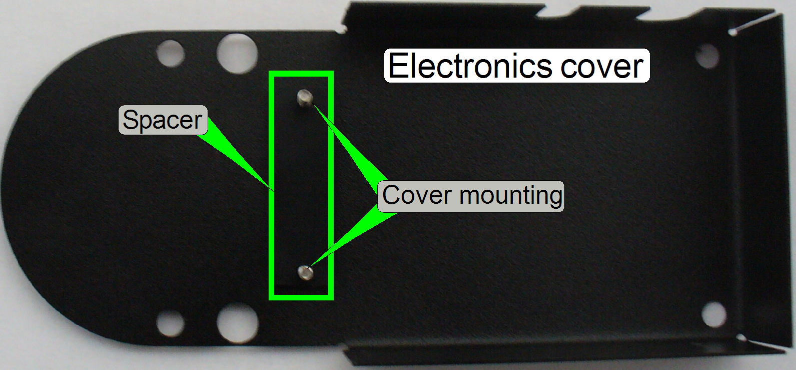
The electronics cover and
·
The Objective Changer mechanics with Objective Disc, form-fit mechanism and
objective mounting.
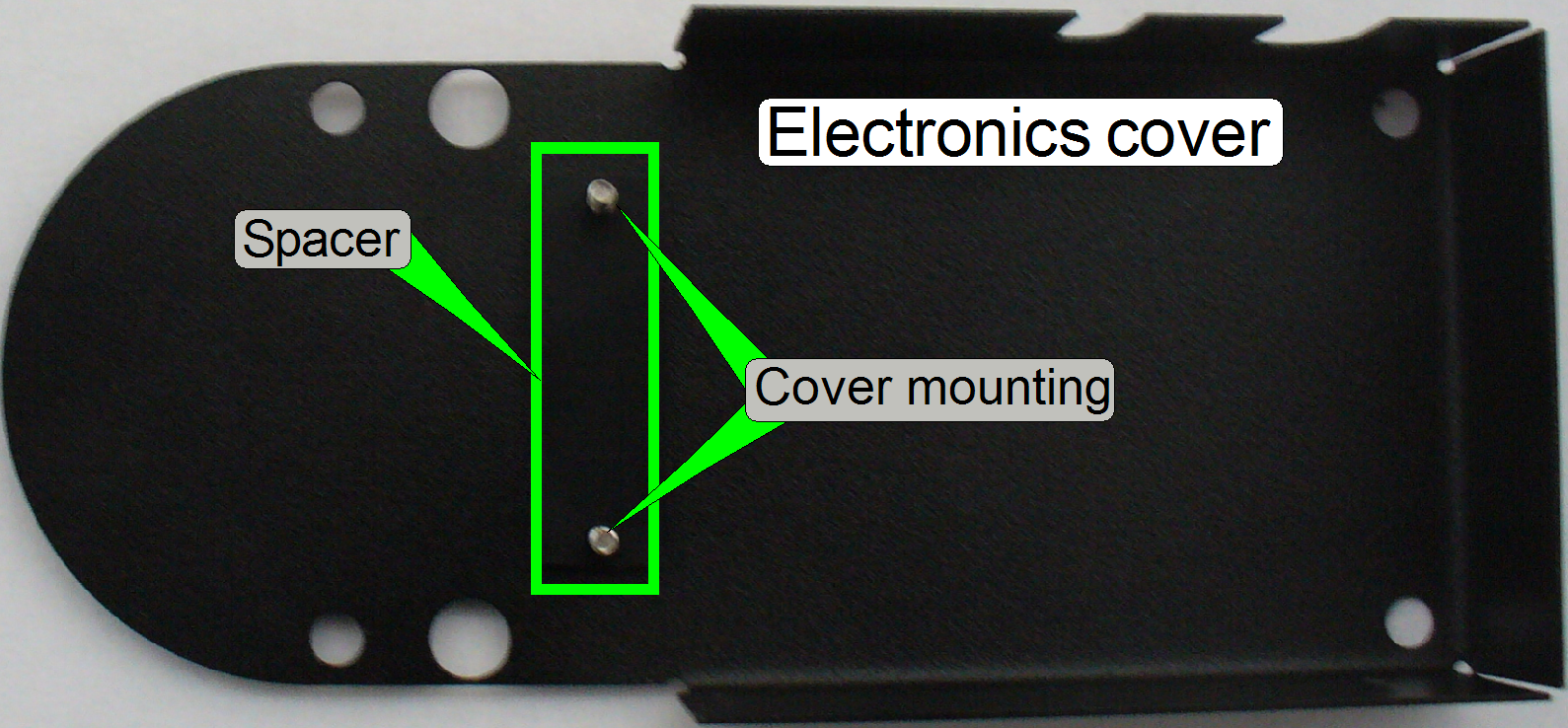 The spacer in the
electronics cover keeps a distance between cover and PCB and avoids so a
shortcut in the electronics.
The spacer in the
electronics cover keeps a distance between cover and PCB and avoids so a
shortcut in the electronics.
 The address of the
control electronics is 09.
The address of the
control electronics is 09.
- The units do not need maintenance or
adjustments.
 See also: “Power
and control” and “Addresses”
See also: “Power
and control” and “Addresses”
“USB-Controller”
and “Connections”
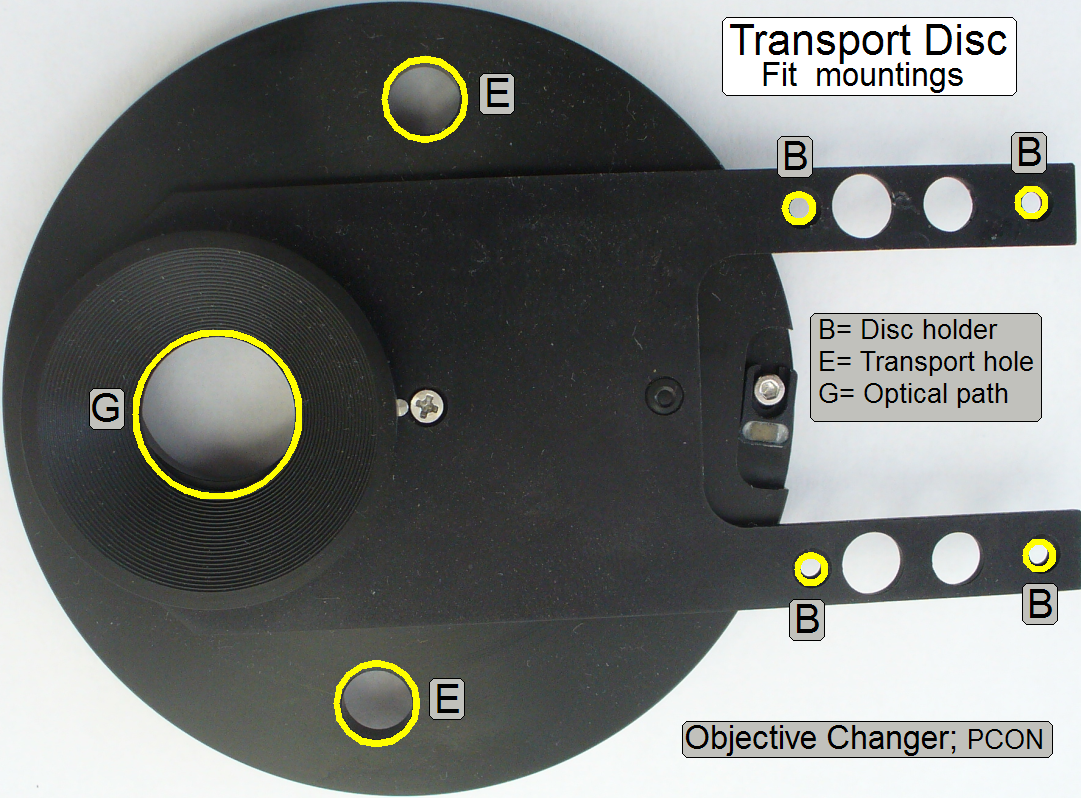
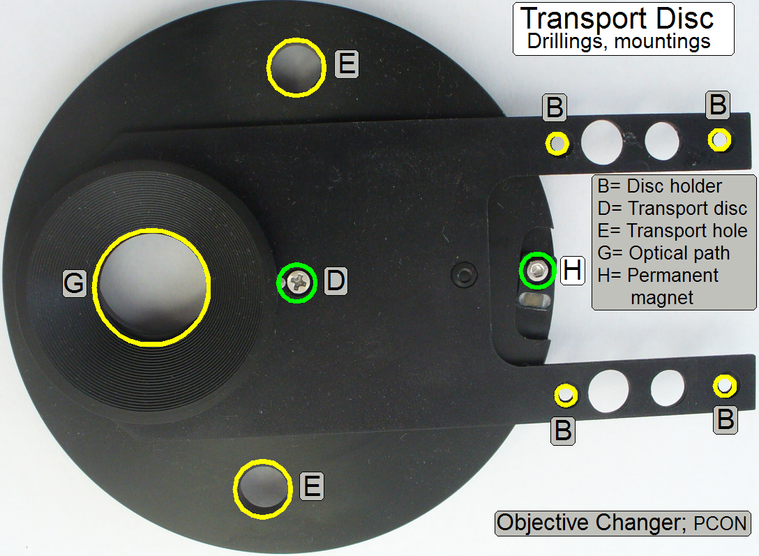 The Transport Disc
is used to rotate the Objective Disc.
The Transport Disc
is used to rotate the Objective Disc.
The permanent magnets are
deciding the objectives’ position via Hall sensors.
·
To cross the dead point of the form-fit arm safely,
the permanent
magnets’ position is adjustable!
- The unit does not need maintenance.
·
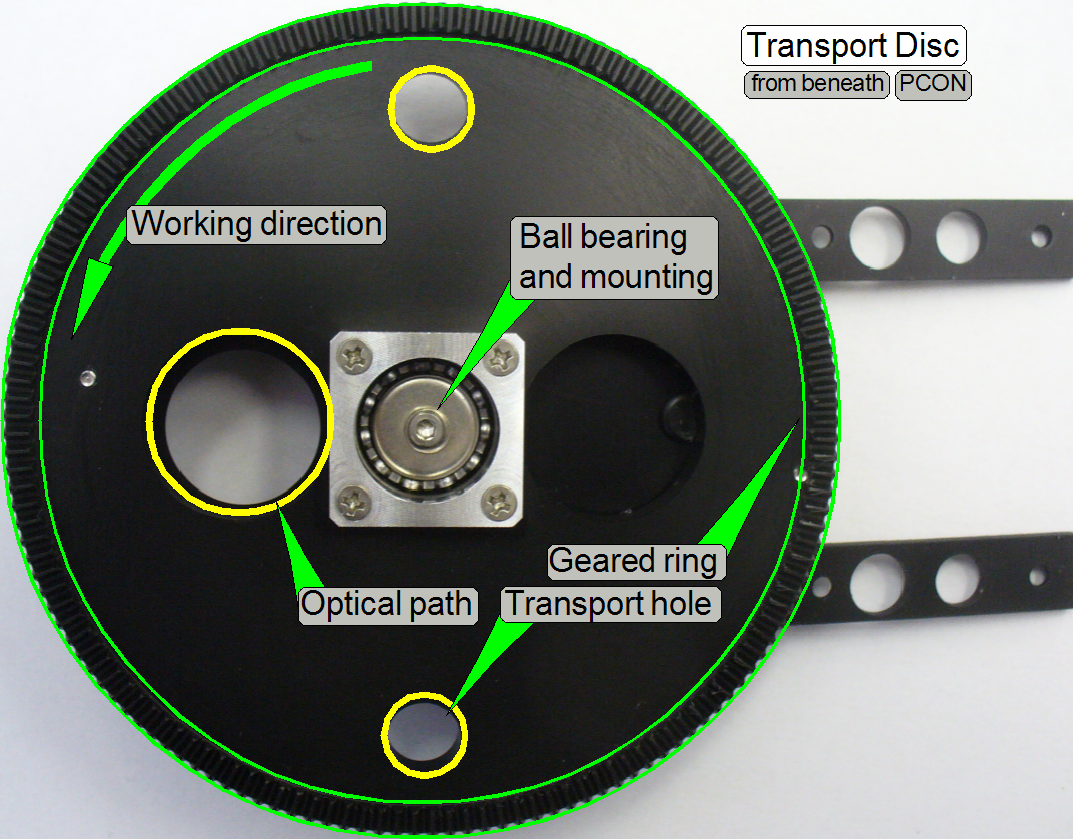 The geared ring is
driven by the DC-motor.
The geared ring is
driven by the DC-motor.
·
If the Transport Disc rotates, the transport holes are
rotating the Objective Disc
via the Transport Pins.
·
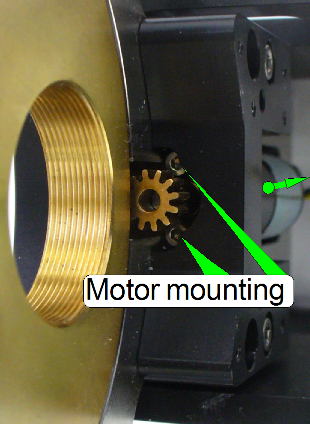
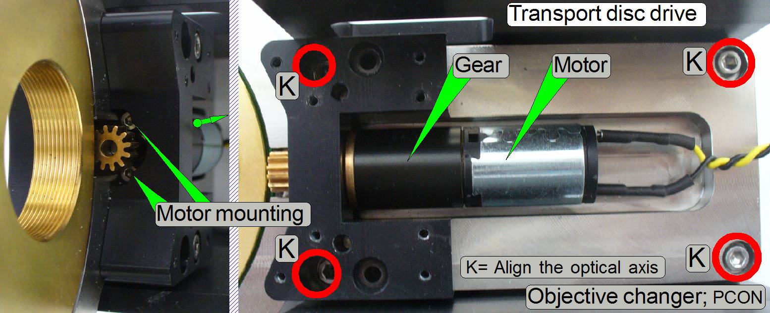 The gearwheel on
the motor (gear) axle drives the geared ring of the Transport Disc.
The gearwheel on
the motor (gear) axle drives the geared ring of the Transport Disc.
·
The motor with gear is mounted by two bolts as shown
- The unit does not need maintenance or
adjustments.
·
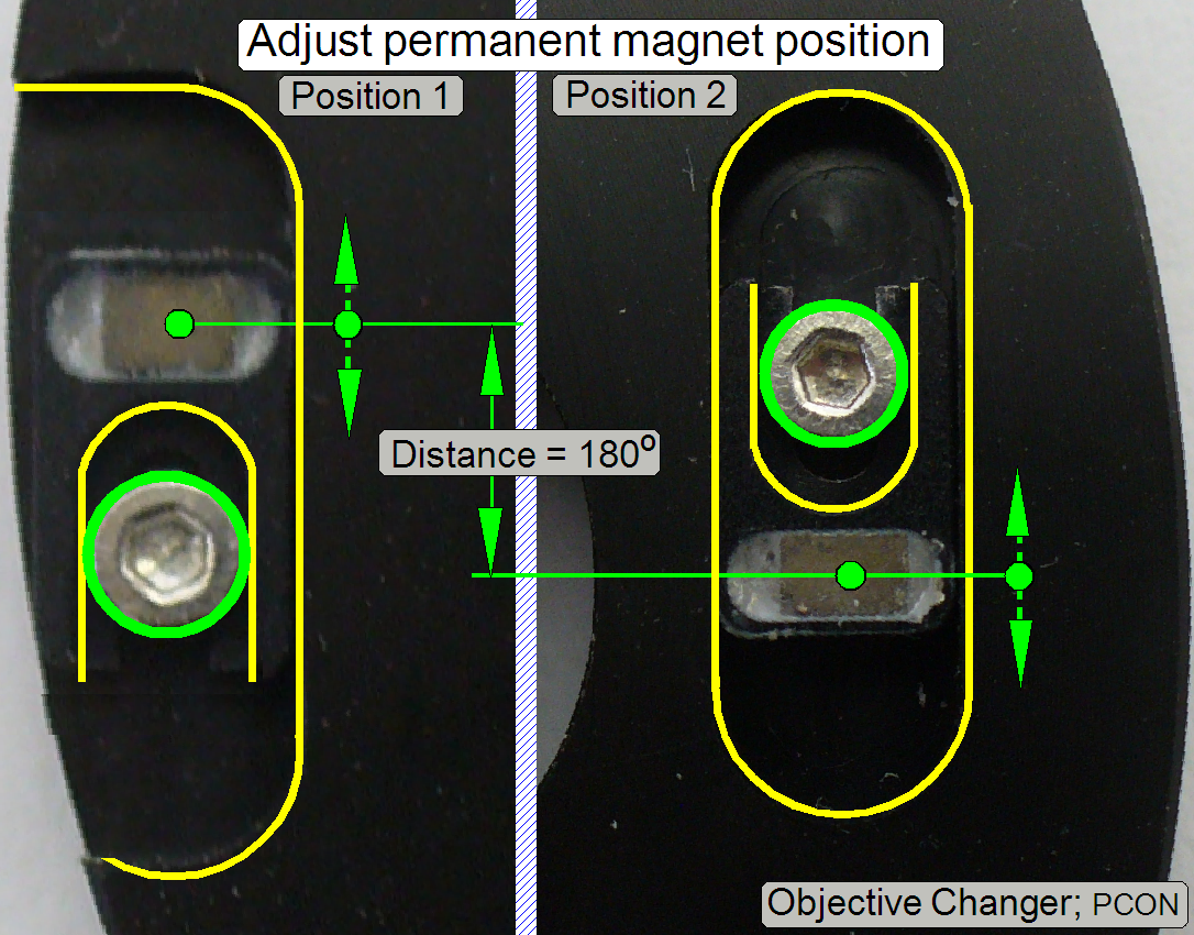
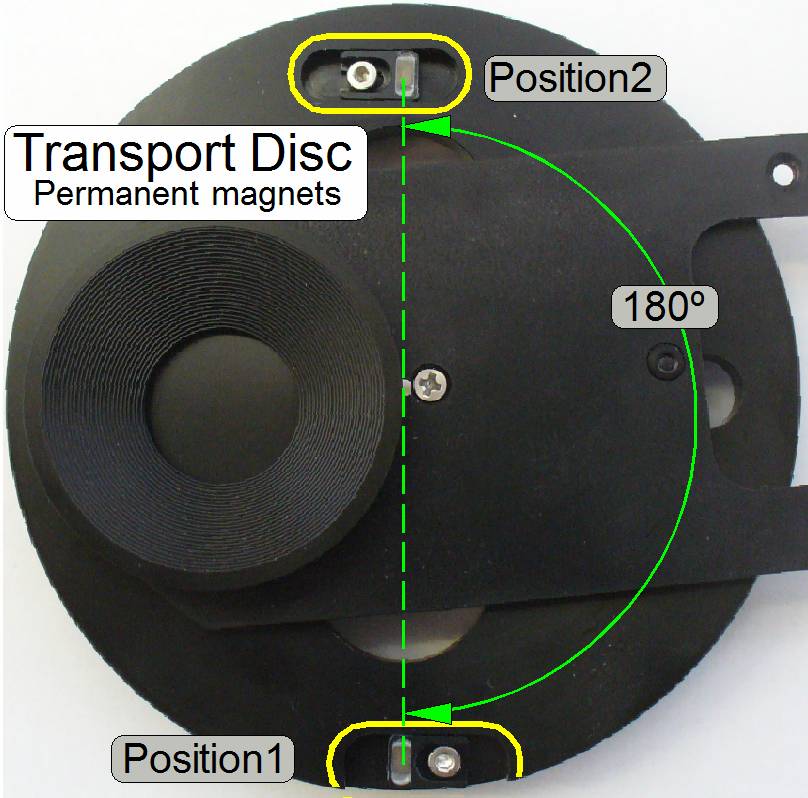 If one permanent
magnet position is moved backward (or forward) the permanent magnet in the
opposite position should be moved also backward (or forward) by the same
distance!
If one permanent
magnet position is moved backward (or forward) the permanent magnet in the
opposite position should be moved also backward (or forward) by the same
distance!
·
To
reach a correct adjustment, the distance of the permanent magnets to each other
has to be always 180º!!
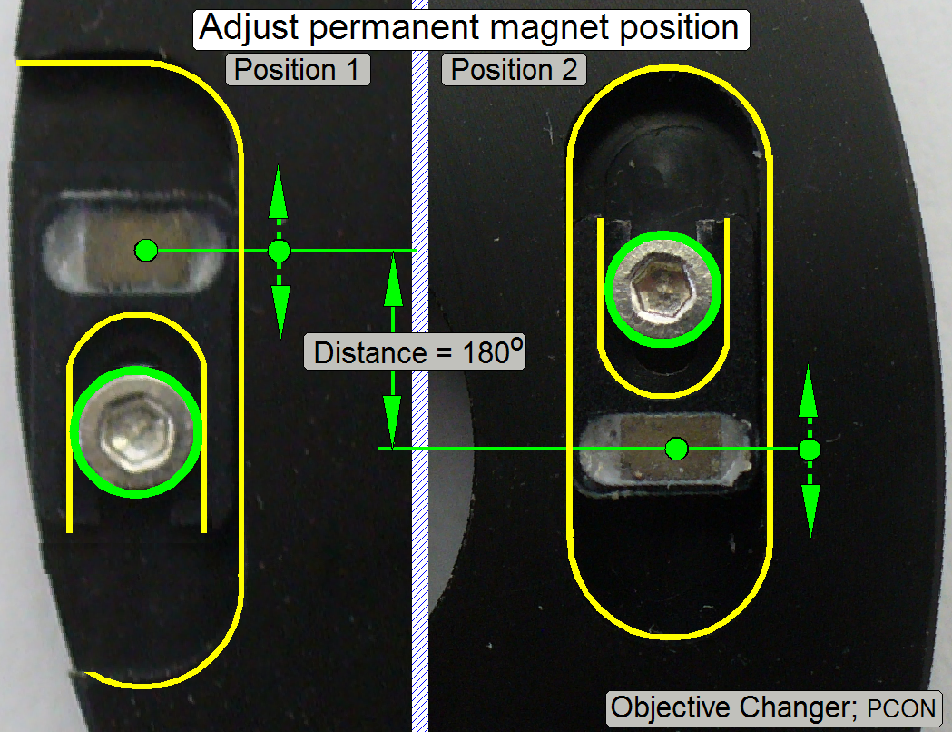 With this
solution, and by adjusting the magnet position, the dead point of the form-fit mechanism
can be always crossed surely.
With this
solution, and by adjusting the magnet position, the dead point of the form-fit mechanism
can be always crossed surely.
See: “Adjust permanent magnet position”
Watch video: “P250_Objective change”
·
If one permanent magnet position is moved backward (or
forward), the permanent magnet in the opposite position should be moved also
backward (or forward) by the same distance!
·
To
reach a correct adjustment, the distance of the permanent magnets to each other
has to be always 180º!!
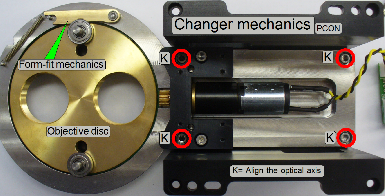 The Objective Disc holds the
objectives and is driven by the transport pins.
The Objective Disc holds the
objectives and is driven by the transport pins.- The form-fit arm, together
with the ball bearing of the transport pin guarantees the proper and
constant objective position in the light path, even if the objective has
been exchanged.
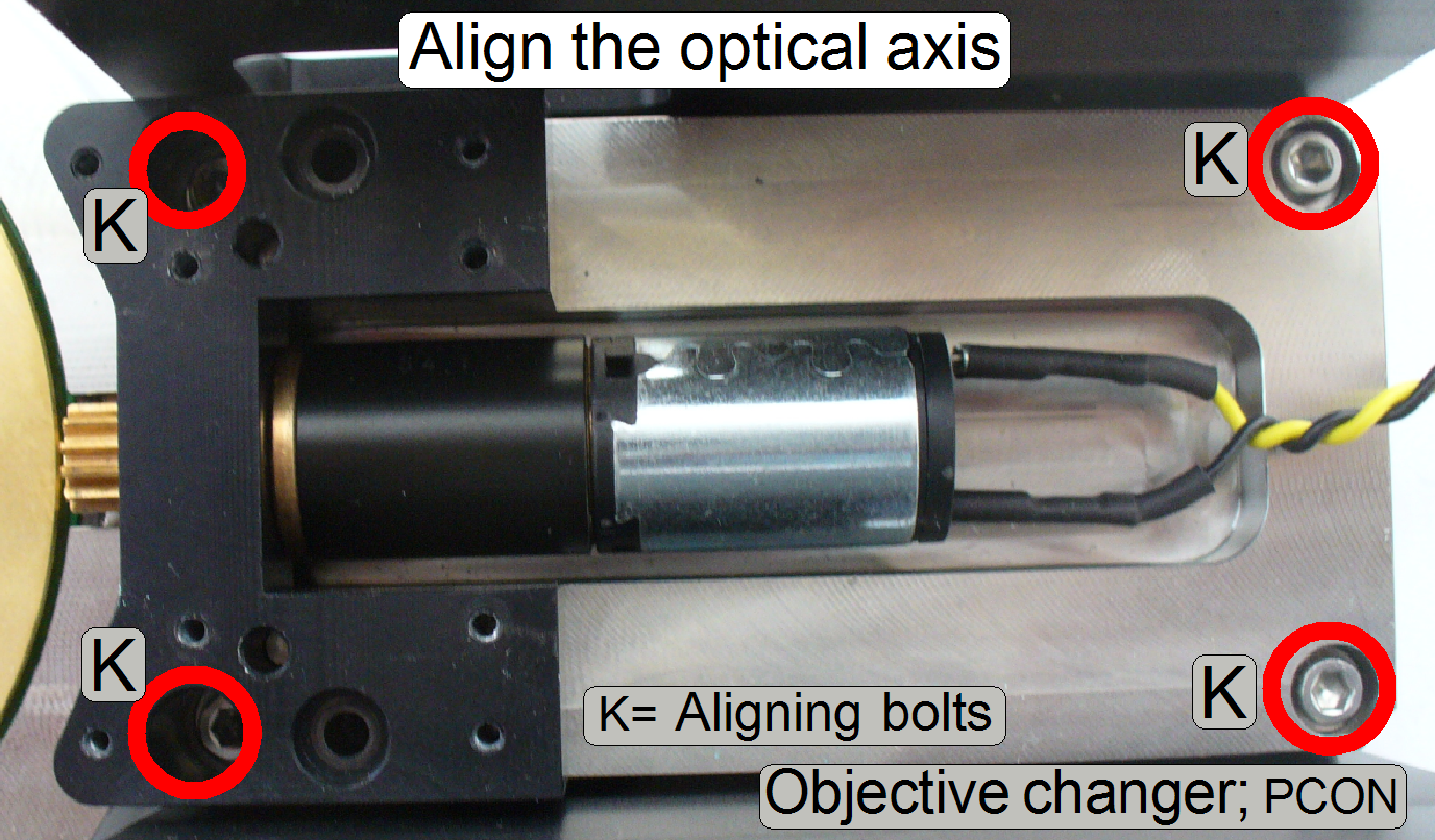
- The unit
mounting of the Objective Changer mechanics should not be loosened or removed (bolts, named wit “K”), because
the working position of the objective in relation to the optical axis is
adjusted here; see first “Align
the objective”.
Important
The Transport Disc can be
separated from the Objective Changer mechanics unhesitatingly, but please do not remove the Objective Changer
mechanics from the holder brackets (bolts, named wit “K”); see “Align
the objective into the optical axis” first!
 The Objective Disc
realizes the exchange of the objective between two slide scan sessions.
The Objective Disc
realizes the exchange of the objective between two slide scan sessions.
If the Transport Disc (not shown)
rotates by a half revolution, the Objective Disc will be rotated also as long
as the connection between transport hole and transport pin exists. The force of
the form-fit mechanism is defined by its spring and this holds so the objective
(the ball bearing of the transport pin) always in the proper position until a
new objective change command is executed.
·
The Objective Disc can be rotated manually in any
direction to reach the required objective position.
·
The form-fit mechanism
should always fix the objective position; otherwise, the optical axis will be
incorrect!
- The unit does not need maintenance or
adjustments.
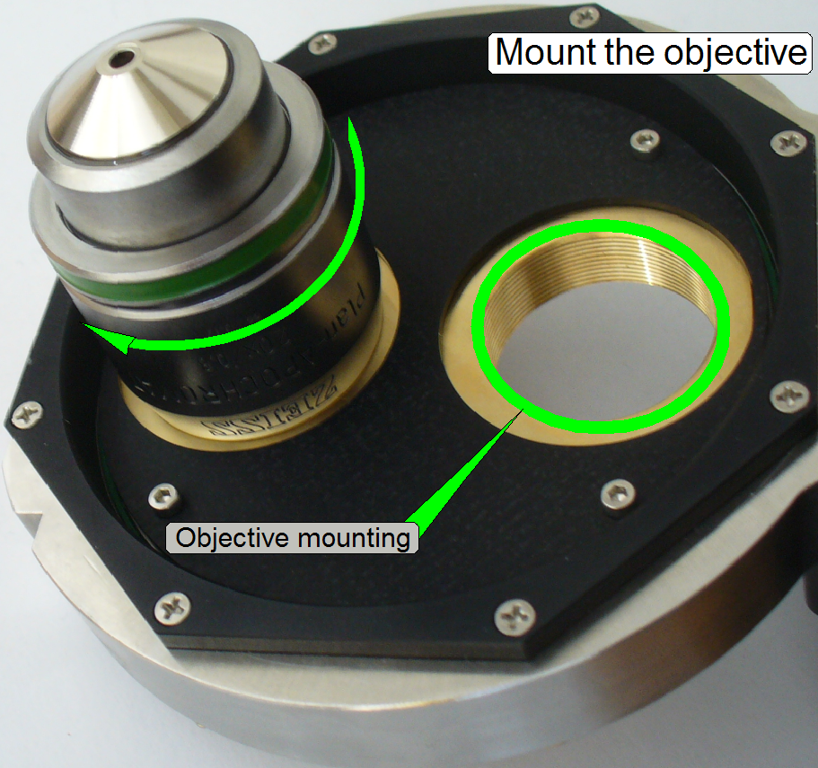
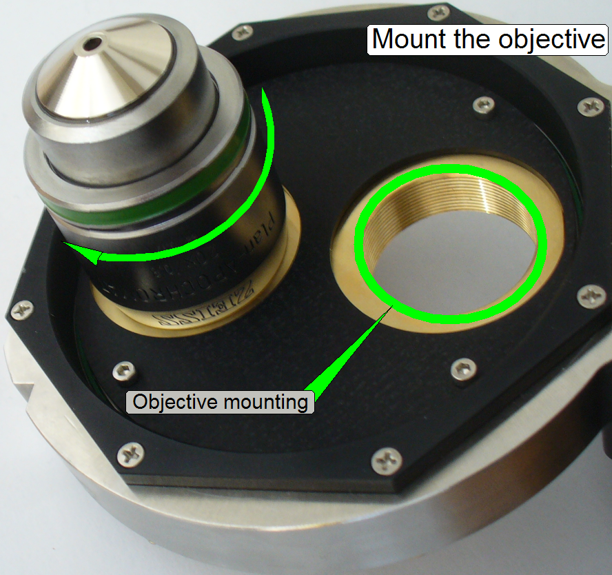 The objective
is driven into the threaded M27 mounting until it stops. The
adjustment of the objective position is done elsewhere, not on the
Objective Changer unit.
The objective
is driven into the threaded M27 mounting until it stops. The
adjustment of the objective position is done elsewhere, not on the
Objective Changer unit.- See: “Adjust the objective position”
Remove the objective
·
Drive the appropriate objective out of its mounting
Mount the objective
·
Drive the appropriate objective in
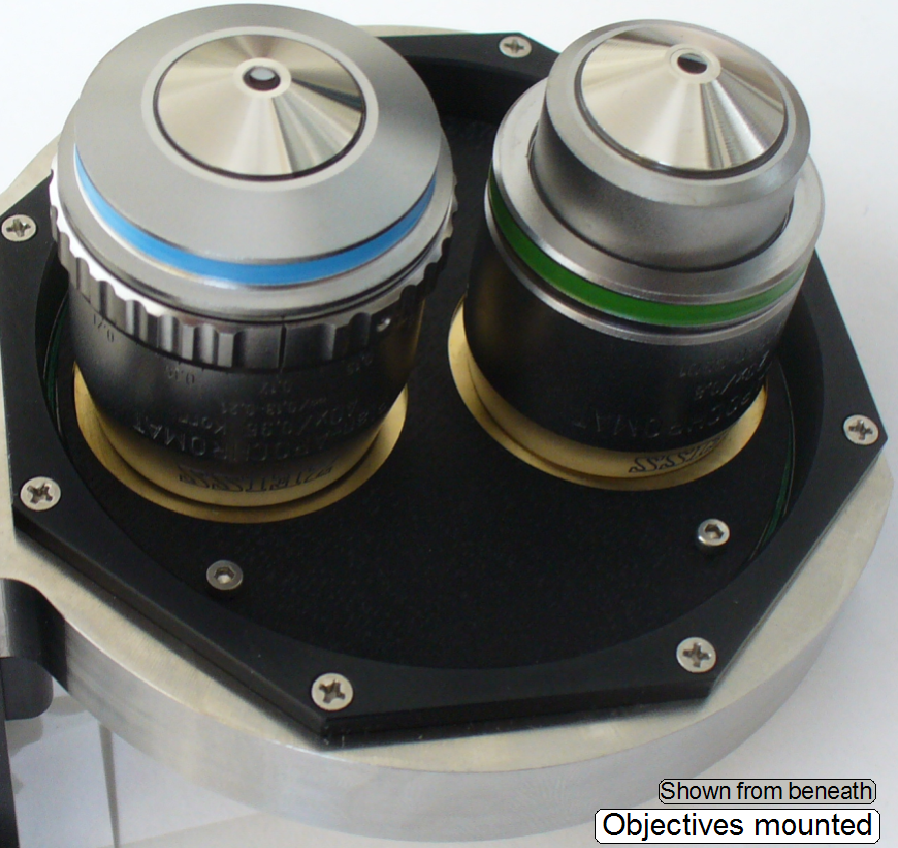
After finishing the objective
mounting procedure, please check the tightness of each objective (again)!!
- See also “Adjust objective position”
 See also “Setup
and define the implemented objectives”
See also “Setup
and define the implemented objectives”
 The form-fit
mechanism acts in the Transport Disc’s
stop position; the final objective position (the real working position) will be
reached and the transport pins will be disconnected from the transport holes.
The form-fit
mechanism acts in the Transport Disc’s
stop position; the final objective position (the real working position) will be
reached and the transport pins will be disconnected from the transport holes.
The force of the spring as
well as the shape of the form-fit arm guaranties always the proper and constant
position of the objective in relation to the optical axis.
- See also “Align
the objective”
·
Because the dead point must be crossed, the transport
pin will not stay in the center of the transport hole if the optical axis is
reached, but a gap has to exist between both transport holes and pins in the
working position; the transport hole has to release the transport pin if the
DC-motor is switched off.
 The disc is always
driven in direction from the spring to the mounting of the form-fit arm (while
normal operation); the reason for this is the shape of the form-fit arm.
The disc is always
driven in direction from the spring to the mounting of the form-fit arm (while
normal operation); the reason for this is the shape of the form-fit arm.
The use of ball bearings on
essential, important mountings guarantees the proper position of the objective
in the image path.
If the ball bearing of the
transport pin arrives to the form-fit arm, and the dead point of the form-fit
mechanism is even crossed, the transport wheel stops the movement and the ball
bearing of the transport pin will be locked in the shape of the form-fit arm by
the force of the spring.
The transport hole of the
Transport Disc moves the Objective Disc with the help of the transport pin
until the appropriate magnet
arrives over its sensor. This position is so defined, that the dead point
of the form-fit mechanism is even crossed.
 The following procedure
assumes that the Objective Changer is mounted and should not be
dismounted.
The following procedure
assumes that the Objective Changer is mounted and should not be
dismounted.- If the
Objective Changer is already removed from the tilting table, you can
easily dismount or mount the
objectives.
1.
With the
program SlideScannerService.exe Set the X-Y-stage to the positions Y-Home1,2
and X-Home1,2.
2.
In the tab “Objective Changer” of the service program
move the objective (position), to be dismounted or mounted into the working
position.
3.
Select the option “Time out”, set a numerical value of
1300 ms and press the button Backward.
4.
Dismount
or mount the objective by hand.
5.
Select the appropriate sensor and press the button
forward; the actual dismounted position or the mounted objective should move
into the working position.
6.
Repeat the steps 2 to 4 with the other objective
(position), if required.
7.
If the 40x objective was mounted, check and set the
thickness of the cover slip; see also “The 40x objective”.
Remove the Objective Changer unit
·
 Disconnect the
power and control cable.
Disconnect the
power and control cable.
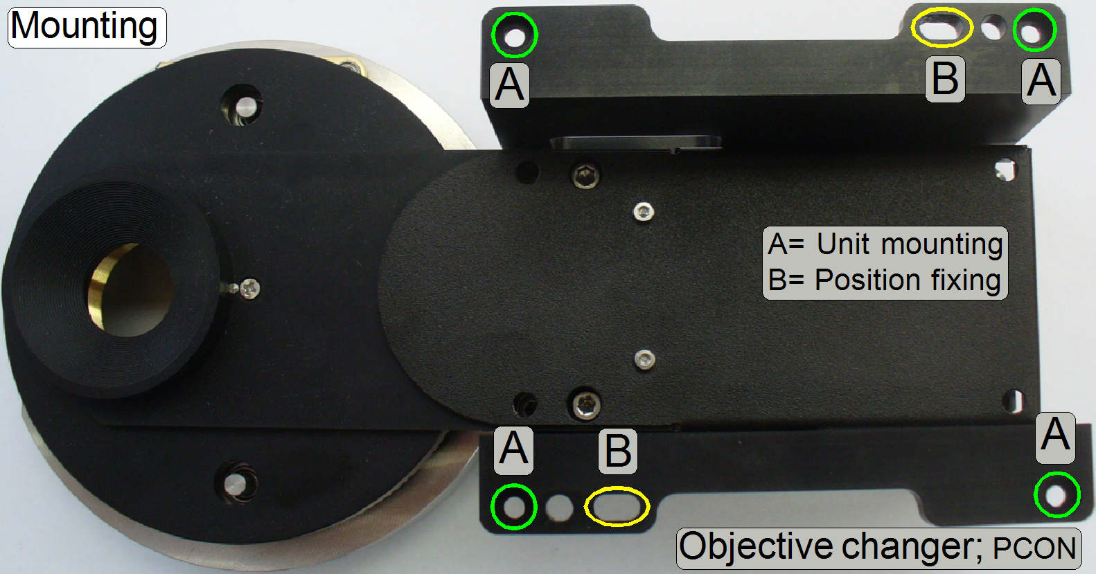
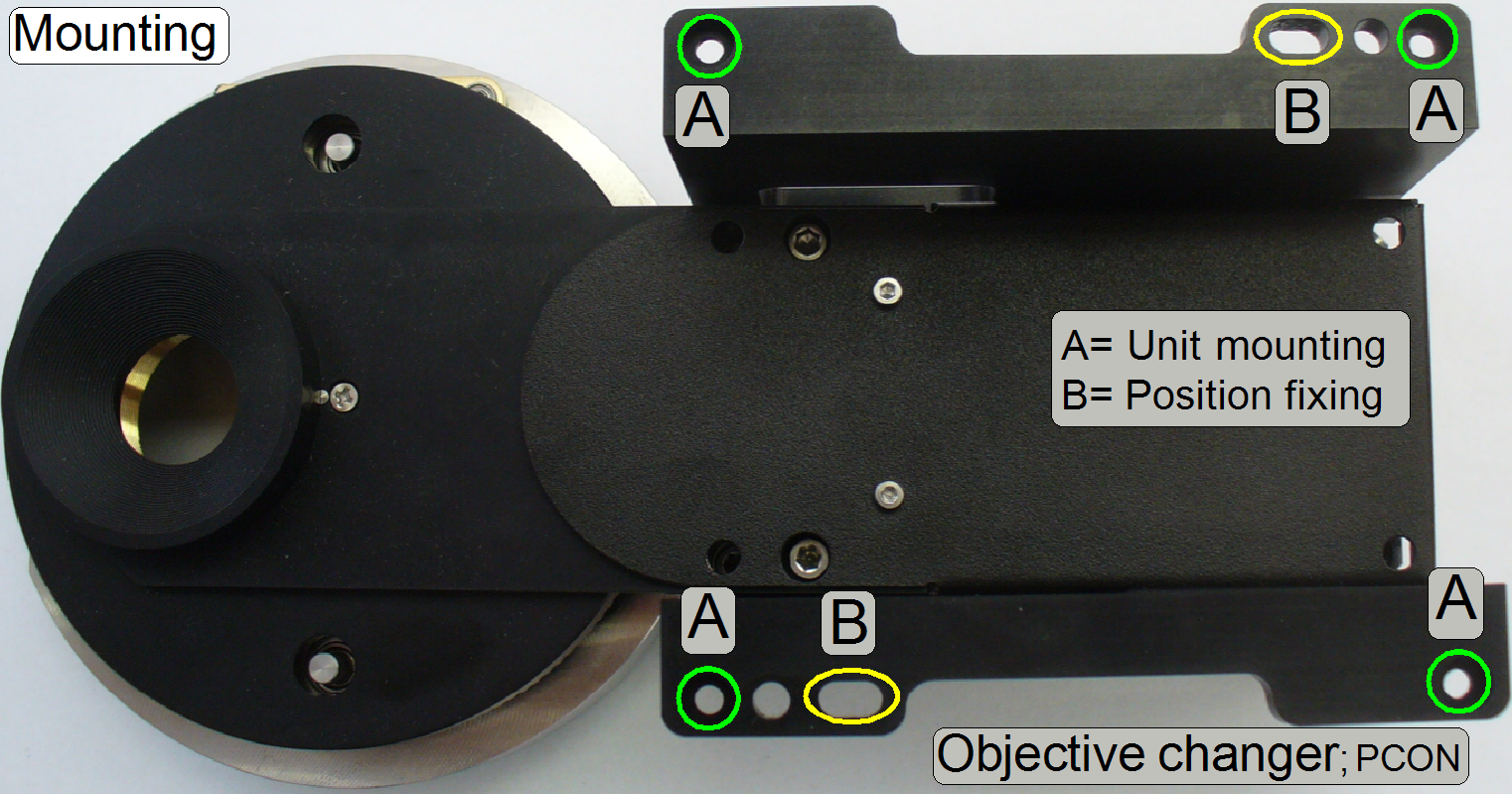
·
Remove the bolts “A”.
·
Pull the unit upward and remove it from the tilting table.
·
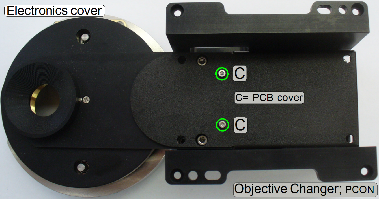 Remove the bolts
“C” and
Remove the bolts
“C” and
·
Pull the electronics cover upward
Remove the spacer also
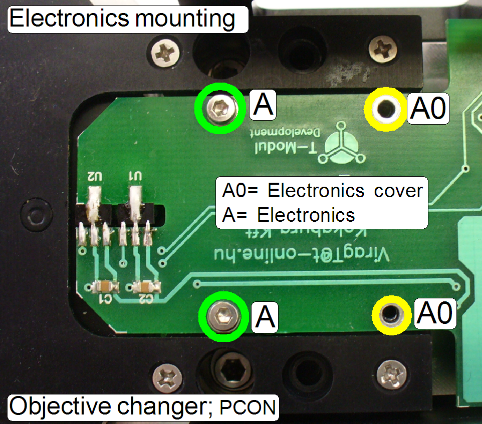
·
Remove the bolts “A” then
·
Remove the electronics upward and to the right.
·
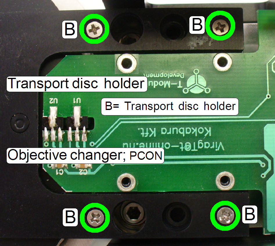
Remove the bolts “B” and move the Transport Disc with
holder to the left.
1.
Remove the
Objective Changer unit.
2.
Remove
the PCB cover and the electronics mounting bolts.
3.
Remove the mounting
bolts of the Transport Disc.
4.
Easily separate the Transport Disc from the Objective
Changer mechanics.
·
Remove the motor mounting bolts and pull out the motor
to the right.
·
 Drive the
objective manually into its mounting until it stops!
Drive the
objective manually into its mounting until it stops!
·
Momentarily, if the Transport Disc is not mounted, the
position is likewise.
If the Transport Disc is mounted:
With the service program set:
·
the objective position 1
and mount the 20x objective.
·
the objective position 2
and mount the 40x objective.
If the Objective Changer
unit should not be dismounted
 With the service program
·
Rotate the appropriate objective position into the
working position
·
Rotate the objective position by 1300ms backward with
the option “Timeout”.
·
Drive in the objective manually, until it stops.
·
Rotate the Objective Disc into the working position by
using the radio buttons “Sensor 1 and
·
Check the functionality of the Objective Changer in
its mounting position with the service program several times; rotate the disc
always forward!
Watch video: “P250_Objective change”
·
 Rotate
the 20x objective into the working position manually
Rotate
the 20x objective into the working position manually
·
Rotate the Transport Disc in
relation to its holder so, that the permanent magnet of the “Position
·
Fit the transport holes “E” onto the
transport pins and
·
Fit the mounting “B” of the Transport
Disc holder to the appropriate drillings
·
The gearwheel should engage the
geared ring
·
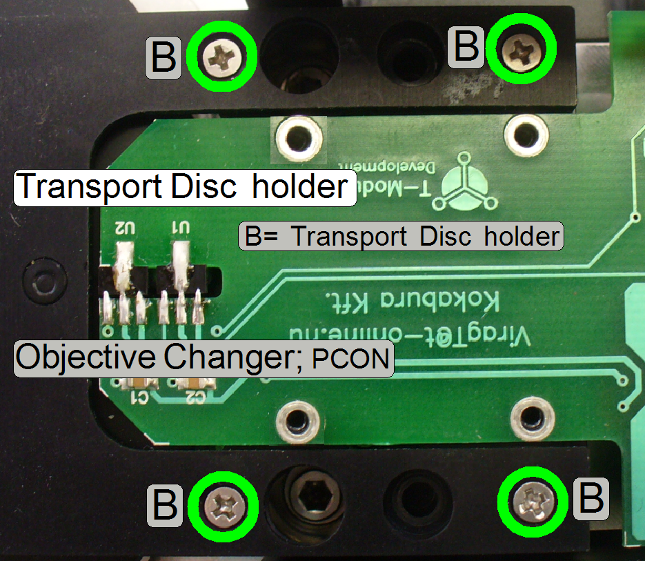 Drive
in the bolts “B”
Drive
in the bolts “B”
.
·
Fit the control cable connector
mechanically into the bracket
·
Place the PCB as shown and
·
Drive in the bolts “A”
1.
Connect the cable CON-12 to the bus
connector.
2.
In the tab “Objective Changer”, of the service program
select the sensor 1 and press the button “Forward”.
3.
Check the correct
movement of the Objective Changer and its mechanics with the service program.
4.
If the form fit mechanism does not snap in during the
normal exchange operation, modify a little bit the appropriate permanent magnet
position until the dead point of the form fit mechanism is crossed correctly.
5.
Continue with the next step.
Check Objective position 1 and 2
4.
Connect the power and control cable.
5.
 Start the service
program.
Start the service
program.
6.
Hold the Objective Changer unit in its mounting
position! In the tab “Objective Changer”, select the “Sensor
7.
Doe the check of the working position with both
objective positions several times!
Set the Objective position 1
10.
If the working position 1 is not correct after the
check, remove the Transport Disc and adjust the Transport Disc correctly.
11.
If the form-fit mechanics does not snap in (the dead
point will not be crossed surely), adjust the permanent magnet position more
precise.
Watch video: “P250_Objective change” and
listen the sound also!
·
 Fit
the bolts into the appropriate drillings
Fit
the bolts into the appropriate drillings
·
Fit the spacer onto the bolts
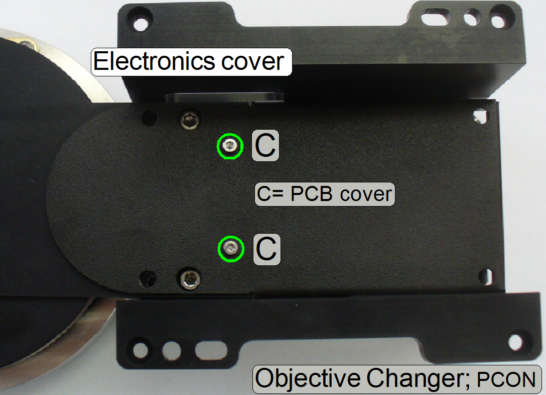
·
Mount the PCB cover; drive in the
bolts “C”.
·
 Remove
the power and control cable.
Remove
the power and control cable.
·
Place the Objective Changer unit
into the tilting table and drive in the bolts “A”.
·
Connect the power and control cable
and Check the working position of both objectives several times with the
service program!
Watch video: “P250_Objective change”
Check
the objective position
See above “Check the Objective
position”
Check the “Stage skew”
Check and adjust the
objective distance to the slide
Adjust the scanner unit base plate
position in height to the nominal focus position!
- This adjustment
assumes that the ex-center position of the focus unit is adjusted well and
so, the sine wave crosses the X-axis at +500 steps and the appropriate
objective is mounted.
To adjust the focus position
you can use a slide with a thickness in the range from 0.95 to
8.
Start the program SlideScanner.exe with the service
password.
9.
Clean the
cover slip and the slide bottom, then insert the measured slide with the
known thickness.
10.
Check the correct holding of the slide in the specimen
holder!
11.
Check the tightness of the objective(s)!
12.
Select a FOV of the tissue inside the preview window
with the positioning tool.
13.
Select the focus tab and live view.
14.
Press auto focus.
15.
If the found focus position is equal with the calculated
focus position for that slide (a deviation of + - 50 steps is possible) the
objective position does not need adjustments; the check is finished.
16.
If an adjustment of the objective position is
required, set the calculated number of focus steps in the live view.
17.
Drive the bolts of the base plate and so, the entire
scanner module, toward or away from the objective until the tissue becomes into
focus and the focus position is reached.
Important!
Please drive all 3 bolts by
the same angle 1/4 revolution or 1/3 revolution or ½ revolution!
Otherwise, the entire scanner part will not move perpendicular and the slide’s
Z-axis will be inclined in relation to the optical axis! See also: “Stage Skew Check”
18.
If the tissue reached the focus position; press the
button “Auto focus” and repeat from step 17.
19.
Check the result again by pressing the button “Auto
focus” some times.
20.
If there are more then 50 steps difference to the
nominal (calculated) focus position, repeat the adjustment from step 18.
21.
Check the focus position on different positions of the
tissue.
22.
Change to the other objective position (tab “Service”,
“Microscope control” select the other objective position and go back to the tab
“Focus”, adjust the exposure time) and check or adjust the focus position for
the other objective by repeating the previous adjustment from step 13.
23.
If the 40x objective was adjusted, check and select
the thickness of the cover slip; see also “The 40x objective”
24.
After finishing the objective position adjustment
check the tightness of each objective (again)!!
25.
Execute the “Stage Skew Check”
26.
If the objective position and parallelogram adjustment
is correct, check
and adjust the condenser position (again)!
Check the objective position alignment
Important
By executing the alignment check, adjustments might be
lost!
1.
 With the service
program set the Objective Changer into the default position by pressing the
radio button “Sensor
With the service
program set the Objective Changer into the default position by pressing the
radio button “Sensor
2.
Disconnect the cable of the Objective Changer.
3.
Remove the
Objective Changer.
4.
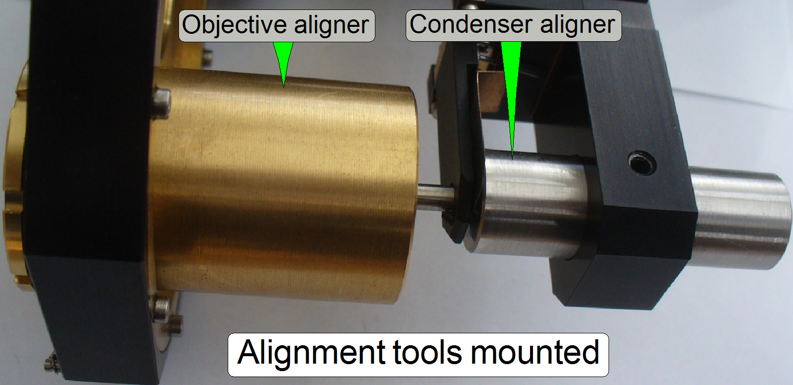
Exchange
the 20x objective with the
objective aligner.
5.
Mark the condenser position (e.g. with a pen), then remove the condenser.
6.
Make sure, the mechanical shutter is open.
7.
Insert the condenser aligner
into the condenser mounting.
8.
If the condenser aligner moves easily in or out in the
condenser mounting (if it would falling out by gravity) and the form-fit
mechanics fix the objective position correctly, the adjustment is correct.
9.
If the condenser aligner can not be inserted or moves
strong, the objective is misaligned; execute the aligning procedure.
10.
If the aligning result is acceptable, remove the
condenser aligner and mount
the condenser again (until the previously signaled position).
11.
Remove the objective aligner and mount the 20x objective
again.
12.
Connect the cable.
13.
With the service program check the functionality of
the Objective Changer unit as well, the 20x objective has to be in the working
position if ‘Sensor
14.
Check or adjust the objective
distance to the slide.
15.
Check
the focus position
16.
Check or adjust the
condenser position.
The mechanics of the Objective Changer unit does not need adjustments;
the positions of the Hall sensors are fixed, the form-fit mechanics adjustment
is done by adjusting the position of the permanent magnets.
The adjustment is limited to
the following parts:
- Check or
set the working position 1 of the Objective Changer unit.
- Adjust the objective
position
- Adjust the
condenser position
8.
 With the service
program set the Y-stage to Home1,2.
With the service
program set the Y-stage to Home1,2.
9.
Set the X-stage to Home1,2.
10.
In the tab “Objective Changer”, select the sensor 1
and press the button “Forward”; the 20x objective should move into the working
position of the Objective Changer unit, in the specified movement direction and
the form-fit mechanics should snap in correctly.
Set the working position 1
12.
If the working position 1 is not correct after the
check, remove the entire Objective Changer.
13.
Remove the Transport Disc.
14.
Rotate the Objective Disc by a ½ revolution so,
that the 20x objective stays in the optical path.
15.
Mount the Objective Changer drive unit.
16.
Mount the entire focus unit with Objective Changer.
Adjust permanent magnet position
 With the service
program rotate the Transport Disc in forward direction.
With the service
program rotate the Transport Disc in forward direction.
If the motor is switched off,
the form-fit mechanics should act and the final objective position should be
reached surely.
Otherwise, a small gap should
also exist between transport hole and transport pin, if the objective stays in the
optical axis.
Check this behavior in both
objective positions several times with the service program!
Watch video: “P250_Objective change”
·
If one permanent magnet position is moved backward, the
permanent magnet in the opposite position should be moved also backward by the
same distance!
·
To
reach a correct adjustment, the distance of the permanent magnets to each other
has to be always 180º!!
Setup and define implemented
objectives
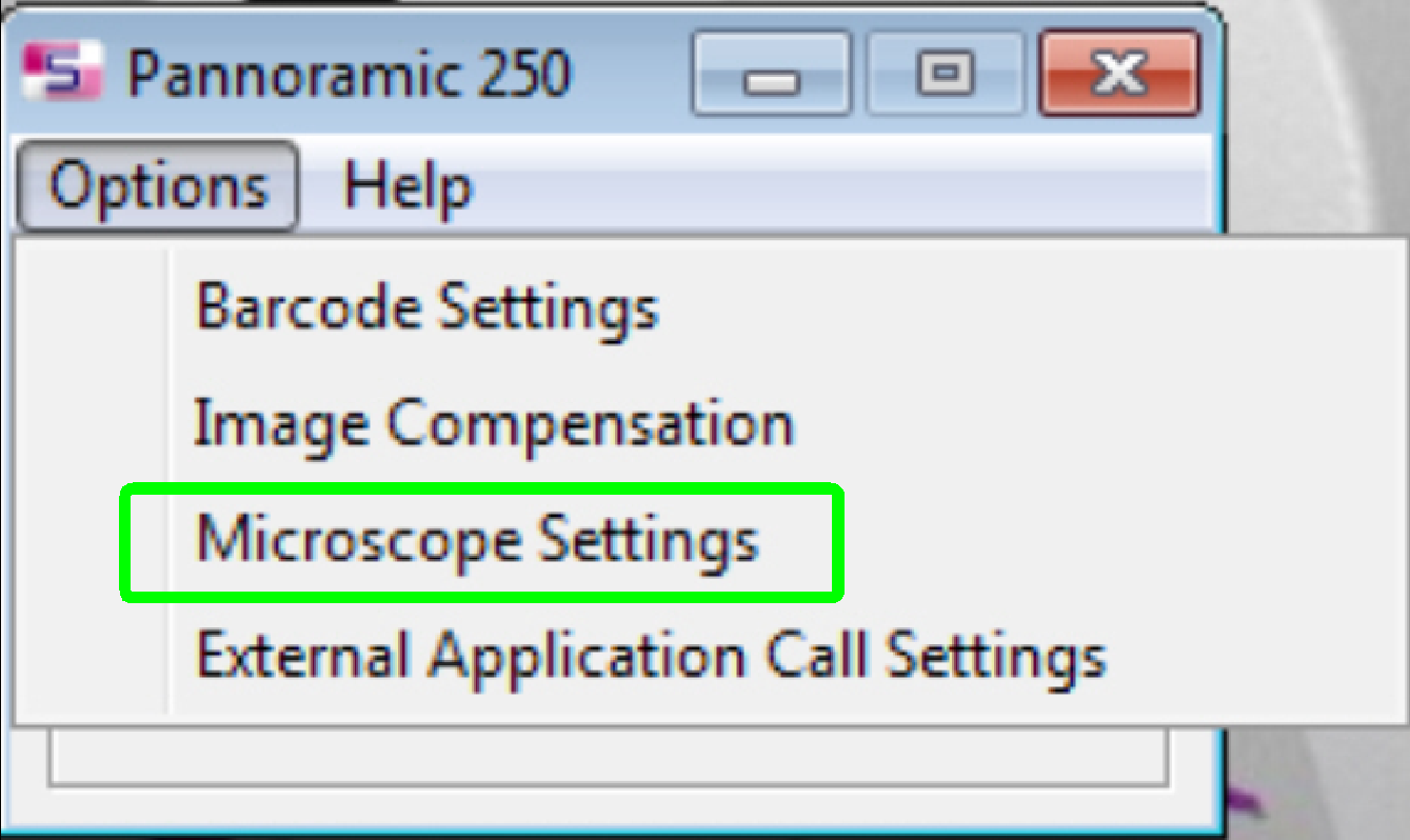 If the
objective(s) are implemented and the program “SlideScanner.exe” finished the
start up procedure, select the option “Microscope Settings” in the menu
“Options”.
If the
objective(s) are implemented and the program “SlideScanner.exe” finished the
start up procedure, select the option “Microscope Settings” in the menu
“Options”.
- The setup of the objective(s) is done
mostly together with the install of the present cameras.
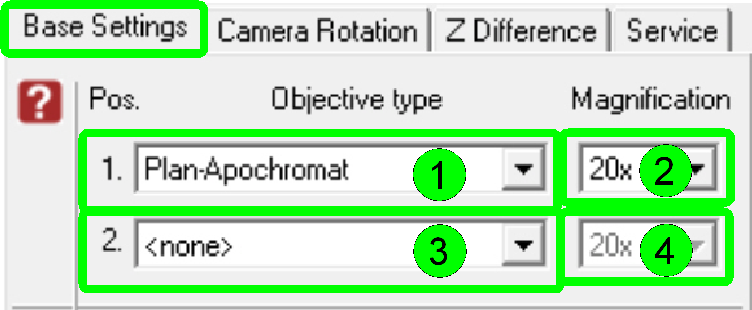 In the dialogue
“Base Settings” the implemented objectives are selected and parameterized.
In the dialogue
“Base Settings” the implemented objectives are selected and parameterized.
By default and in the scanner P250
- Select the type “Plan-Apochromat” (1) and the
magnification of 20x (2) in the objective position 1
- Select the type “Plan-Apochromat” (3) and
the magnification of 40x (4) in the objective position 2.
§
If there is only a 20x objective implemented into the
scanner, select “<none>” (3) in the objective position 2.
Remark
Of course, the dialogue
accepts any kind of magnification in any objective position, but in the
Pannoramic Confocal the 20x objective should be always in the objective
position 1 because this is the default objective and some adjustment procedures
(e.g. the preview
calibration process) uses the 20x objective in the objective position 1!
Align the
objective position into the optical axis
Attention
 The alignment of the objective position to the optical
axis is already done and finished; this is not a usual adjustment.
The alignment of the objective position to the optical
axis is already done and finished; this is not a usual adjustment.
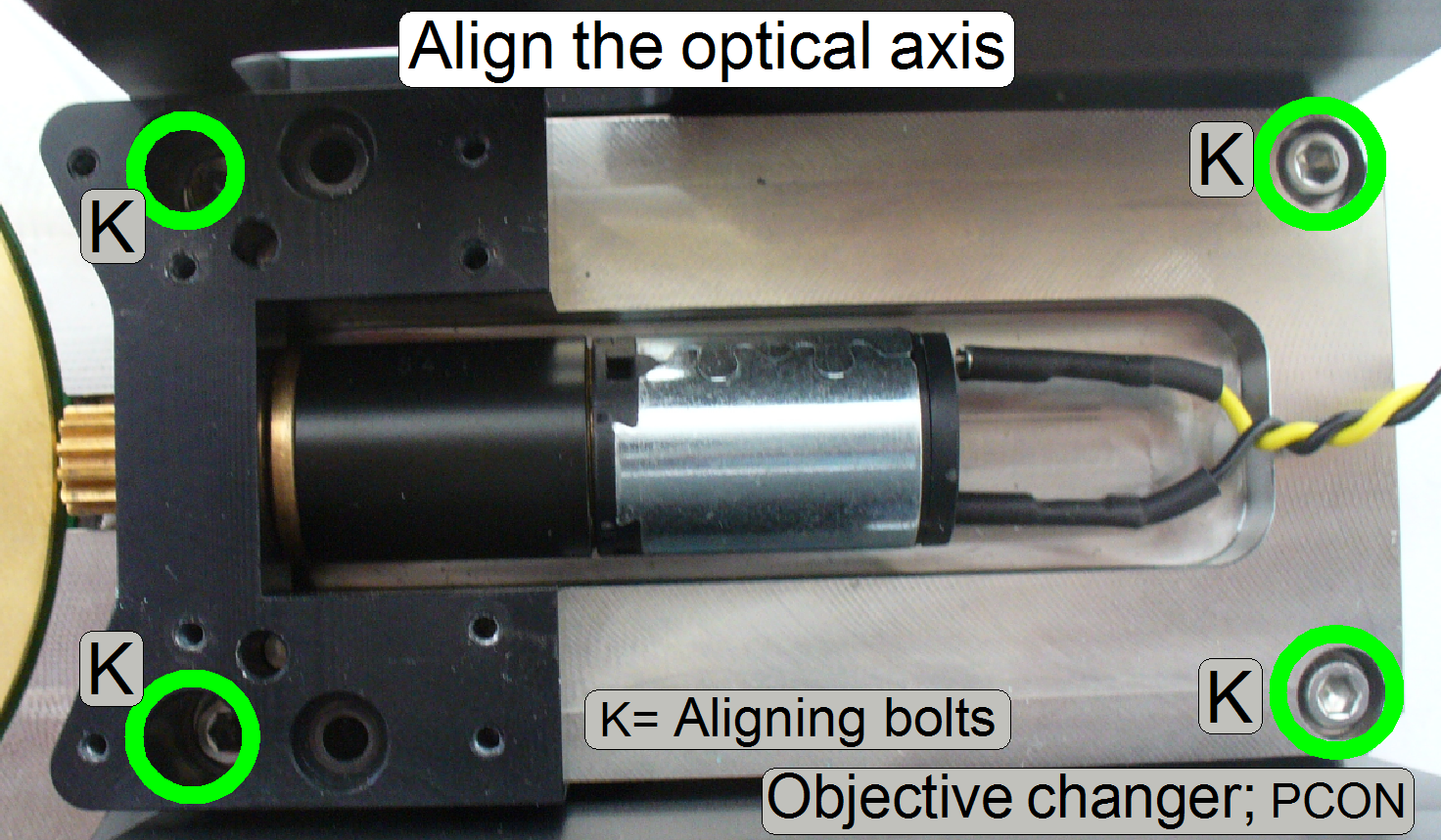
The following calibration
should be done only, if the Objective Changer unit aligning bolts (K) was
loosened, altered or the Objective Changer unit was separated and reassembled
to the mounting brackets; so the optical axis will not be strait.
Please check first
- The following procedure will be used to fit
the objective (position) into the optical axis correctly.
- In any cases, check the alignment
first, before starting the adjustment.
- Check the correct working of the form-fit mechanics
also.
Remark
The aligning procedure is
advised and described for the 20x objective and the objective position 1.
If technical difficulties
exist, you can use unhesitatingly the 40x objective position to align the
Objective Changer unit!
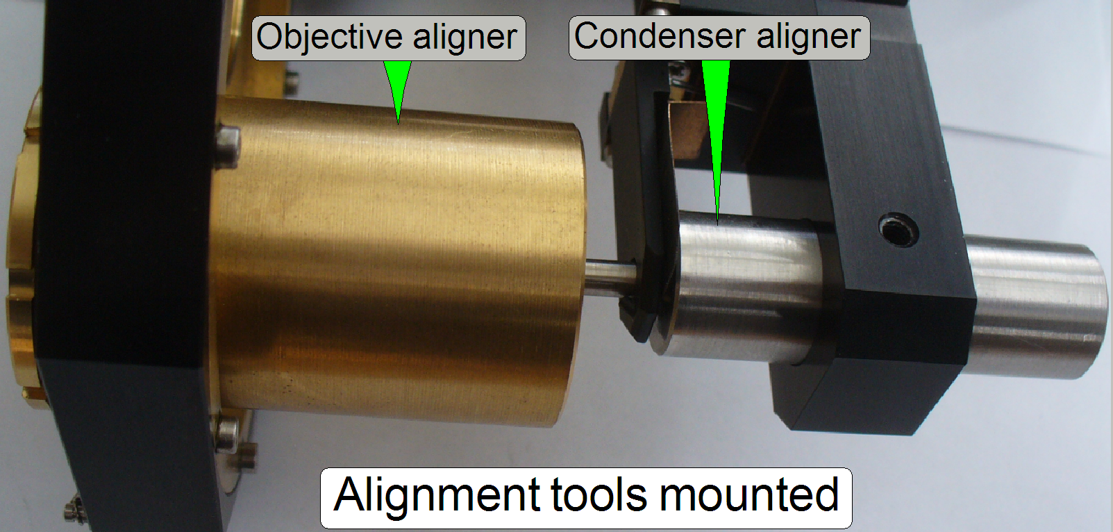
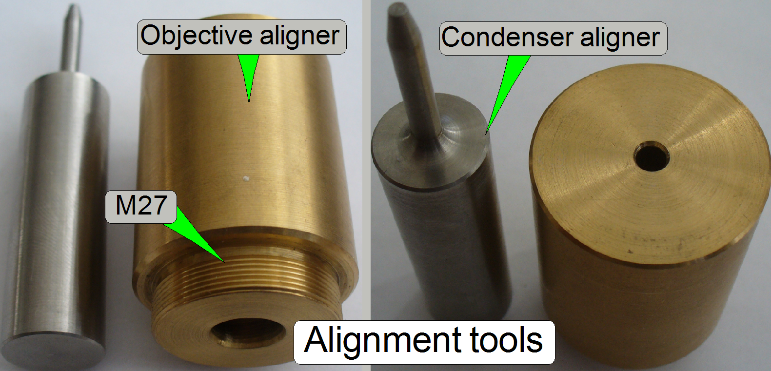 The alignment is
done mechanically; the objective pupil position (represented by the drilling of
the objective aligner) will be fit into the optical axis by the help of the
condenser aligner pin. During this fitting operation the Objective Changer unit
mounting is barely loosened (except you are checking the correctness of the
alignment). The Objective Disc unit mounting bolts will be tightened, if both
adjustment tools fitting easily and the form-fit mechanics fix the objective
position correctly.
The alignment is
done mechanically; the objective pupil position (represented by the drilling of
the objective aligner) will be fit into the optical axis by the help of the
condenser aligner pin. During this fitting operation the Objective Changer unit
mounting is barely loosened (except you are checking the correctness of the
alignment). The Objective Disc unit mounting bolts will be tightened, if both
adjustment tools fitting easily and the form-fit mechanics fix the objective
position correctly.
- In all cases, the objective aligner tool
should be fully tightened during the aligning procedure.
- The alignment tools can also be used to
check the objective position alignment if the Objective Changer unit
mounting is tightened!
1.
 With the service
program set the Objective Changer into the default position by pressing the
radio button “Sensor
With the service
program set the Objective Changer into the default position by pressing the
radio button “Sensor
2.
Disconnect the cable of the Objective Changer.
3.
Remove the 20x objective!
4.
Drive the objective aligner into
the objective mounting of the 20x objective until it stops.
5.
Mark the condenser position (e.g. with a pen), then remove the condenser.
6.
Loosen the unit mounting bolts of the entire Objective
Changer unit so, that the unit becomes barely moveable.
7.
Make sure, the mechanical shutter is open.
8.
Insert the condenser aligner
into the condenser mounting and adjust the entire Objective Changer unit
position in relation to the mounting brackets.
9.
If the condenser aligner moves easily in or out in the
condenser mounting (if it would falling out by gravity) and the form-fit
mechanics fix the objective position correctly, the “Aligning bolts” should be
tightened.
10.
Check the easily movement of the condenser aligner in
the condenser mounting again; hereby the form-fit mechanics should fix the
objective position correctly also.
11.
If the condenser aligner moves strong, repeat this
procedure from step 8.
12.
If the aligning result is acceptable, remove the
condenser aligner and mount
the condenser again (until the previously marketed position).
13.
Remove the objective aligner and mount the 20x objective
again.
14.
Put the 20x objective into the working position.
15.
 With the service
program check the functionality of the Objective Changer unit as well, the 20x
objective have to be in the working position if the radio button “Sensor
With the service
program check the functionality of the Objective Changer unit as well, the 20x
objective have to be in the working position if the radio button “Sensor
16.
Check or adjust the objective
distance to the slide.
17.
Check
the focus position
18.
Check or adjust the
condenser position.