Power, control; P250
For technicians and partly for sales managers!
The Pannoramic scanner P250 got a lot of modifications concerning the
power supply and the electronics also, these modifications are mostly based on the
experiences with the Pannoramic SCAN and the Pannoramic MIDI scanners and the
newly implemented components.
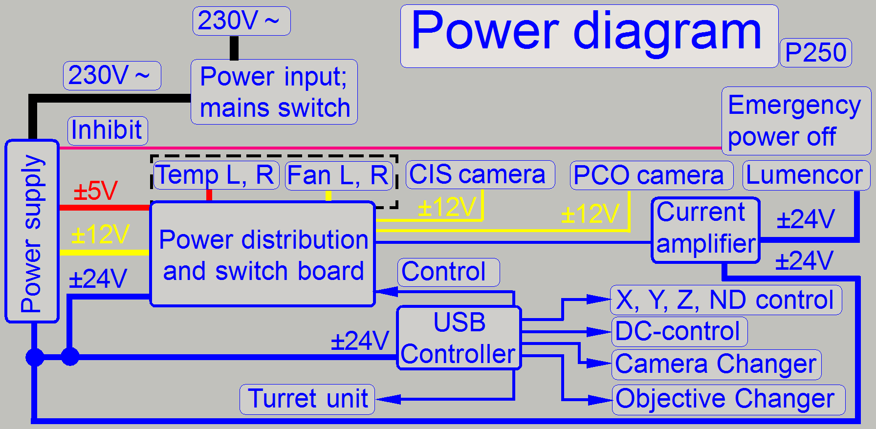
The power supply and control electronics consists of the following
components and units:
- Power input
connector and main switch
- Power supply
- Emergency power off
(standby) switch
- Power
distribution & switch board
- USB Controller with EEPROM
- DC Controller
- X-Y-Z-ND-motor and
Flash light control
- Stepper motor
- Temperature
and fan control.
 The P250
power supply is realized as an internal OEM power supply
module.
The P250
power supply is realized as an internal OEM power supply
module.- The power
distribution for momentarily unused units or in emergency situations
(overheating) can be
switched off by the PIC controller firmware.
- The focus
unit stepper motor was changed to a motor with higher resolution
(6400µ-steps / revolution).
- Control of
the objective changer
- Control of
the camera changer
- Brightfield
flash light control.
- The Neutral
Density (ND) stepper motor.
- The X-Y- Z-
and ND stepper motors does not contain control electronics; the control
electronics for these motors was separated.
- Independent
temperature sensing and regulation by the control of the fans speed.
- Further
sensors are implemented.
- A darkfield
preview illumination was implemented.
- Power supply
and control of the Lumencor SPECTRA light engine.
Important remark
· After
maintenance or
services and performed tests of the scanner are 100% finished, protective
ground connections and other safety regulations related to hazardous voltages,
accessible conductive parts and dangerous to life parts have to be checked
(again).
·
For safety regulations regarding
human health and scanner functionality please refer to: Precautions
Configure electronics components
Since the
software version 1.15 the units of the scanner are configured in the file
“MicroscopeConfiguration.ini”, section [Microscope].
The actual version of the electronics components in the scanner
Pannoramic 250 is defined as follows:
[Microscope]
SerialNumber=xxxx
MicroscopeType=3DMic9
ScanCameraType=
PreviewCameraType=CVrmc_m8_pPro
BarcodeReaderType=PreviewCamera
LoaderType=SL_9Mag_25Slide_Sensor_Vertical
CameraChangerType=CC_None
ReflectorTurretType=RT_None
BrightfieldLightSourceType=FlashLight2010
ObjectiveChangerType=OC_2Pos
ObjectGuideXYZType=OGXYZ_FLASH3
FlashUnitType=FlashUnit_Type2; see
also: The X-,X-,Z-,ND-
and flash controller
NDFilterType=NDType2
PreviewLightType=PreviewLightUnitType_Type1
PowerSwitchBoardType=PowerSwitchBoard_Type1; see also: The power
distribution & switch board
Remark
To enable the X-,X-,
FlashUnitType=FlashUnit_Type2
Actually, the most recent
“Type2” is used.
To disable the X-,X-,
FlashUnitType=FlashUnit_None
To enable the switch board:
PowerSwitchBoardType=PowerSwitchBoard_Type1
Actually, the most recent
“Type1” is used.
To disable the switch board:
PowerSwitchBoardType=PowerSwitchBoard_None
Electrical and
electronics units
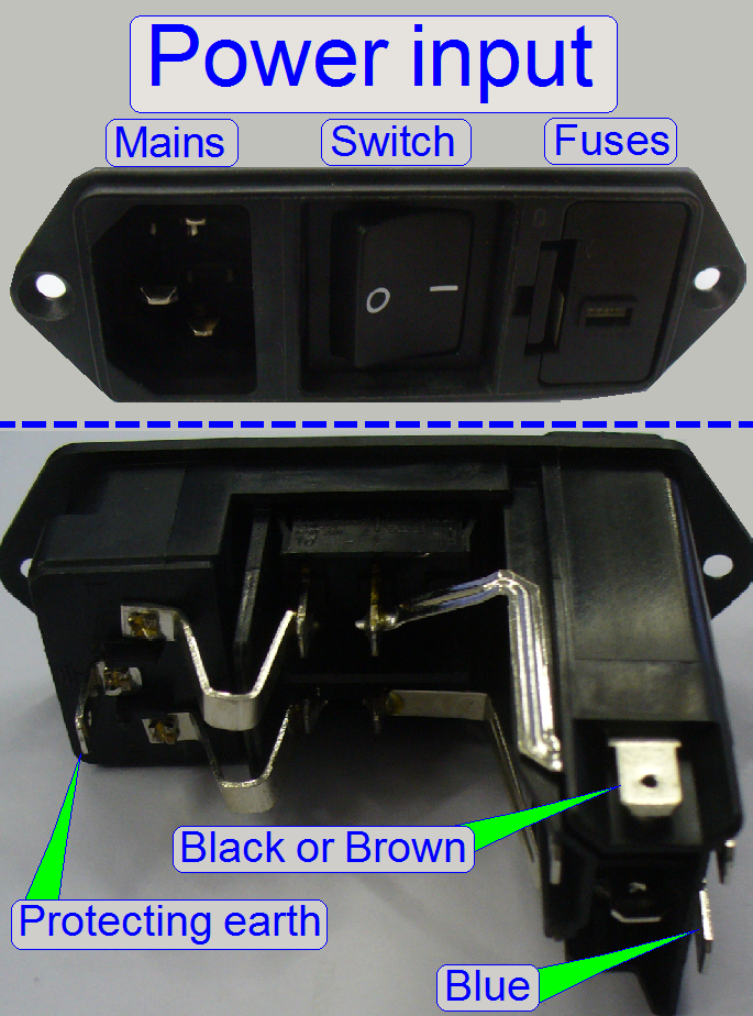
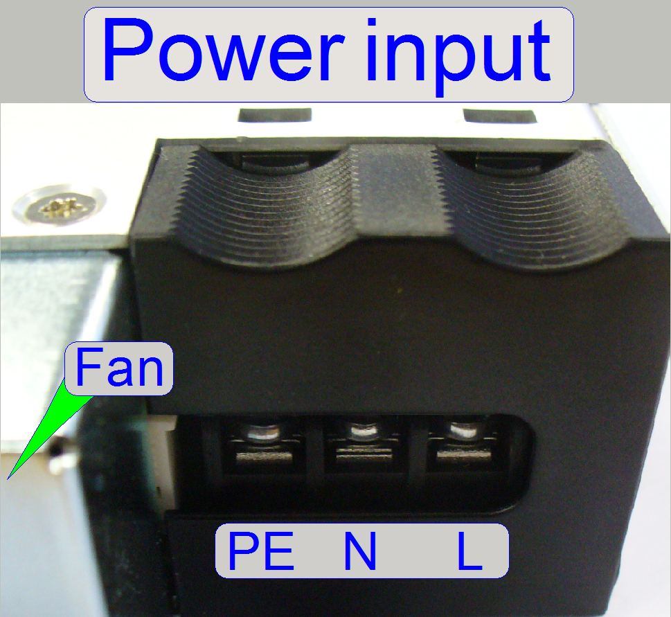
The power input connector and main switch consists of:
- Power cord
connector (Mains)
- Main switch
- Fuse housing
with fuses
The double-pole main switch disconnects the mains power from the
internal power supply.
Each pole is secured by a slow-blow fuse of T3.15 A / 250V.
More information can be found in the “Power input gallery” and the “Power input slide show”
230V~
or 100V~
The alteration of the mains power input in the range from 100V~ to 240V~
is reduced to the use of the appropriate mains power cable!
If the mains power is changed from 230V~ to 100V~ or vice versa, no
alterations are required inside the scanner; the change of the mains power is
fully handled by the input voltage range of the power supply.
![]() “The power supply TDK -Lambda”.
“The power supply TDK -Lambda”.
Check or replace fuses
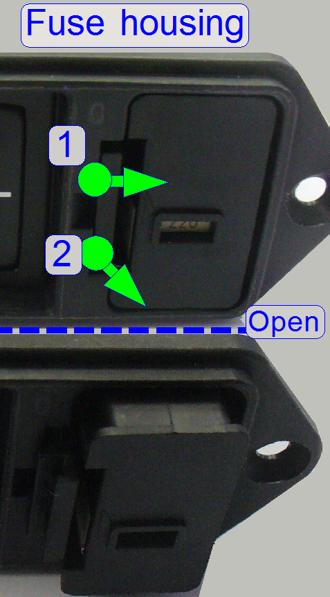
- Disconnect
the power cable.
- Open the fuse
housing and remove the fuse container.
·
Push the fuse container lock guide (1) to the center
of the fuse container (e.g. with a flat screw driver) and pull it out (2) of
its housing.
- If the fuses
are dismounted, please use an Ohmmeter to
check the fuses.
- If a fuse
exchange is necessary, please use always a slow-blow fuse of T3.15 A /
250V (110V~ or 230V~ power input is unimportant).
More information can be found in the “Power input gallery”
Power supply TDK -Lambda
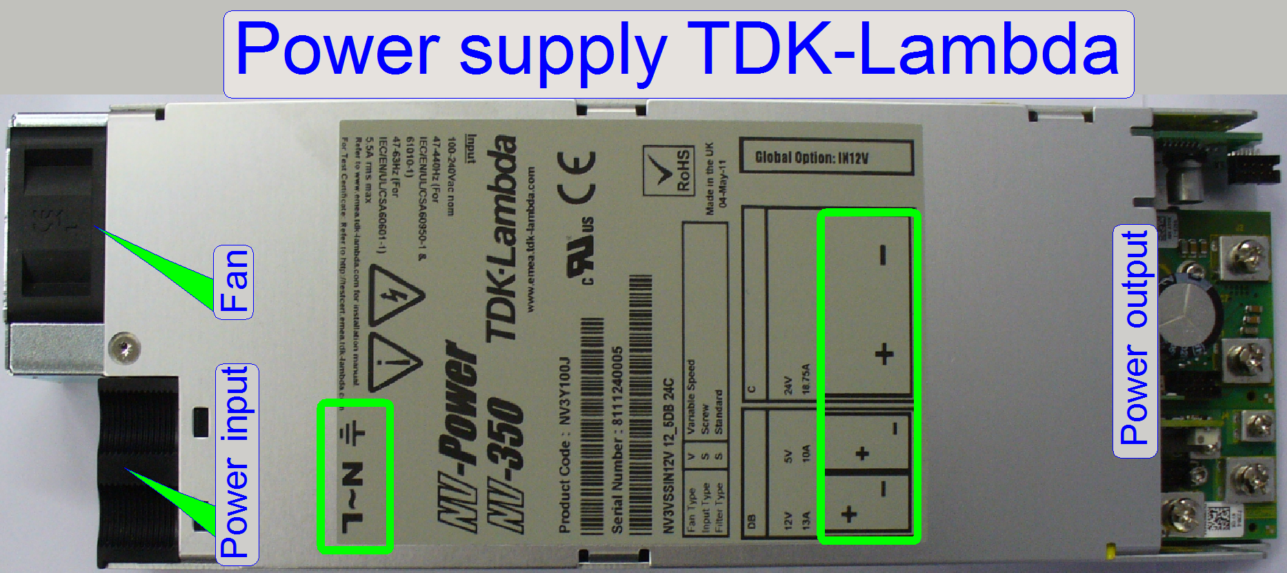
The internal OEM power supply TDK-Lambda with an input voltage range of
100V~ to 240V~ AC and output voltages
of 5V-, 12V- and 24V- DC supplies the internal units of the P250 with power.
Inside the controller units (
·
The power supply is short circuit protected.
·
The “Emergency power off” switch can be used to switch
off the entire scanner if mechanical jamming or any other emergency situation
occurs!
·
If the input voltage is changed from 230V~ to 110V~ or
vice versa, no alterations are required inside the scanner!
Power input
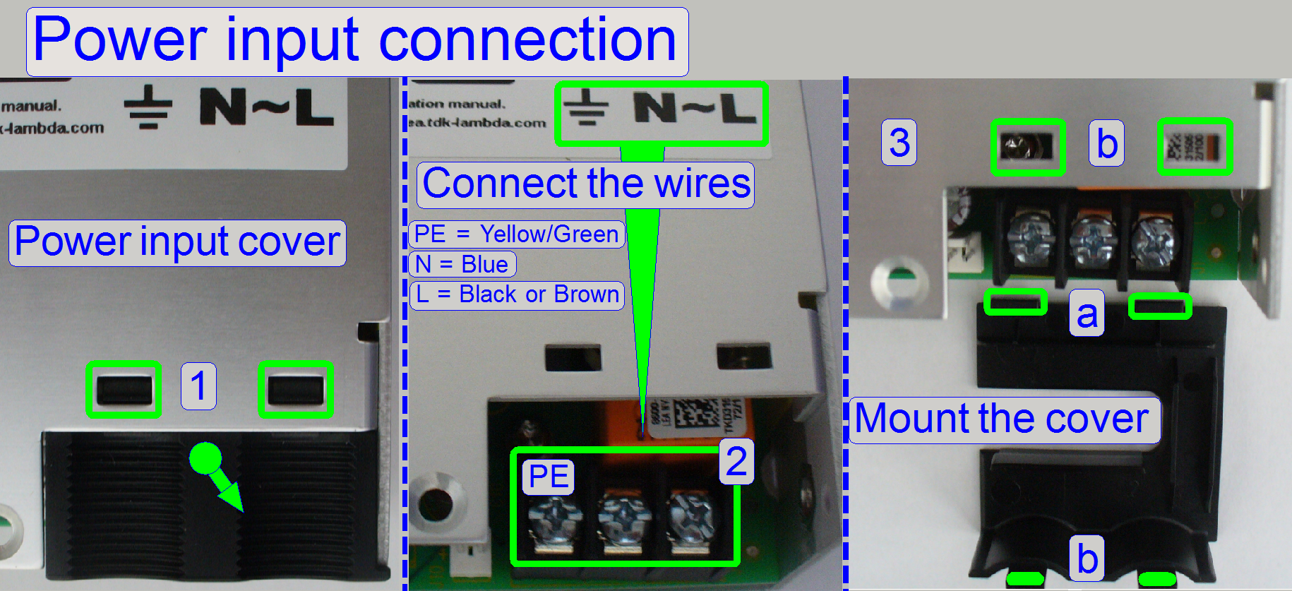
· Press the power
input cover a bit downward until the clamps (1) are disconnected from the upper
housing part and remove the cover.
· Connect the power
wires as shown (2).
· Fit the parts (a)
into the slots of the base cover and the clamps (b) into the appropriate slots
of the top cover.
![]() “Installation manual” (in more languages); stored
“Installation manual” (in more languages); stored
Output voltages; power
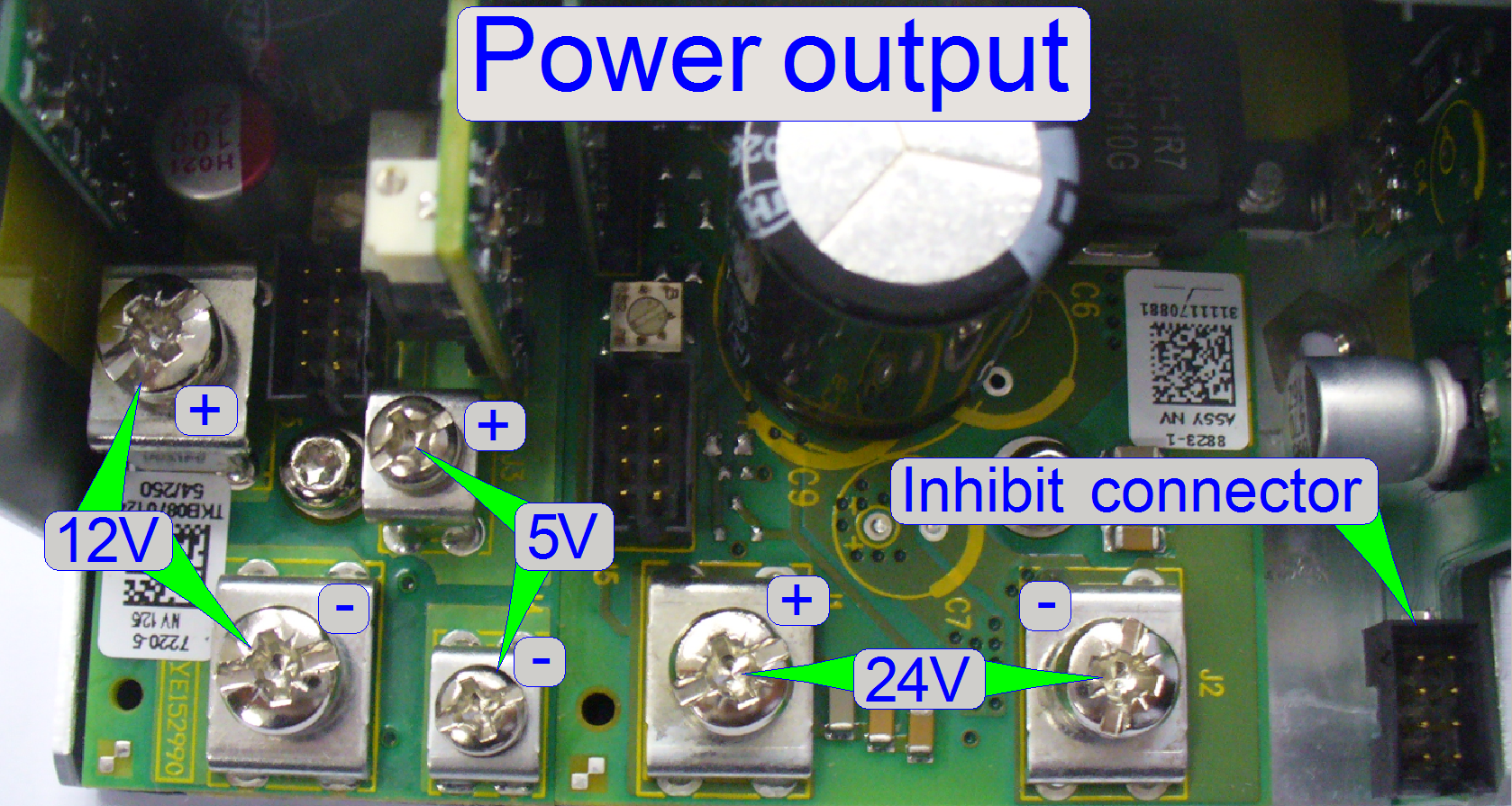
- 5V- /10A DC
- 12V- / 13A DC
- 24V- / 18.75A
DC
The outputs are short circuit protected and are ground independent (the
minus pole is not connected to GND)
so each voltage has a plus (+) and a minus (-) pole.
![]() Power_supply_tdk_Lambda_REV
18.1.pdf (stored in this
description)
Power_supply_tdk_Lambda_REV
18.1.pdf (stored in this
description)
Emergency standby
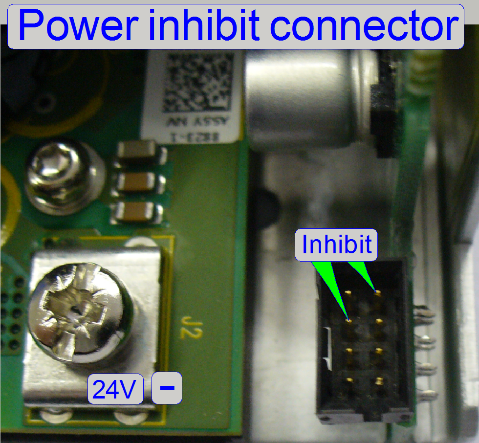
 The Emergency switch inhibits
and stops the switching power supply, but the mains voltage of 110V~ or 230V~
is not interrupted; the power supply goes to standby!
The Emergency switch inhibits
and stops the switching power supply, but the mains voltage of 110V~ or 230V~
is not interrupted; the power supply goes to standby!
By shorting the 2 pins “Inhibit” (the voltage between the two pins is
about 15V-) the power supply control is inhibited and all output voltages are
disabled (standby mode).
If there is no connection between the two pins (or the standby option is
not used), the power supply is running continuously.
- These two
pins will be shorted, if the “Emergency power off switch” is active and
closed!
![]() “Switch
“Emergency power off””
“Switch
“Emergency power off””
 The emergency
power off switch is situated in the right handed side wall of the scanner and is
used to inhibit the power supply; the power distribution is interrupted and all
movements are stopped immediately.
The emergency
power off switch is situated in the right handed side wall of the scanner and is
used to inhibit the power supply; the power distribution is interrupted and all
movements are stopped immediately.
- If the power
is supplied again to the scanner, the software has to be started
again!
Mounting of the power unit
 The entire power
unit (power supply, power distribution and switch board and the current
amplifier of the Lumencor SPECTRA) is mounted onto the power supply
“TDK-Lambda”.
The entire power
unit (power supply, power distribution and switch board and the current
amplifier of the Lumencor SPECTRA) is mounted onto the power supply
“TDK-Lambda”.
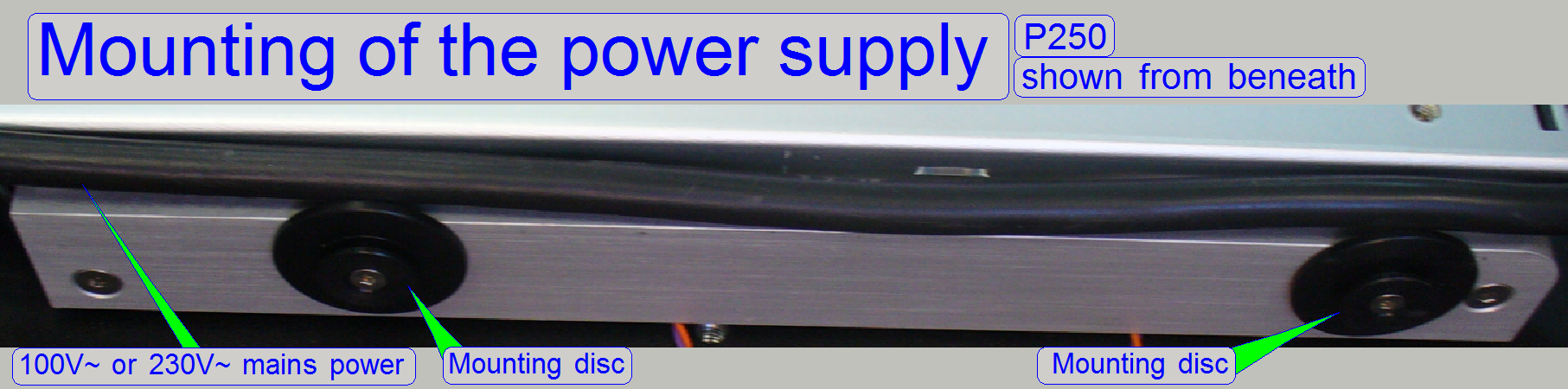
On the lower edge of the power supply mounting discs are situated from
beneath, so the power supply can be shifted in the mounting rail, situated on
the bottom of the power box.
Please shift the entire power unit only frontward or rearward.
If the power unit will be inclined sideward or upward during the removal
or insert procedure, the mounting discs will be destroyed!
![]() “Base plate
and housing truss”
“Base plate
and housing truss”
Power distribution and
switch board
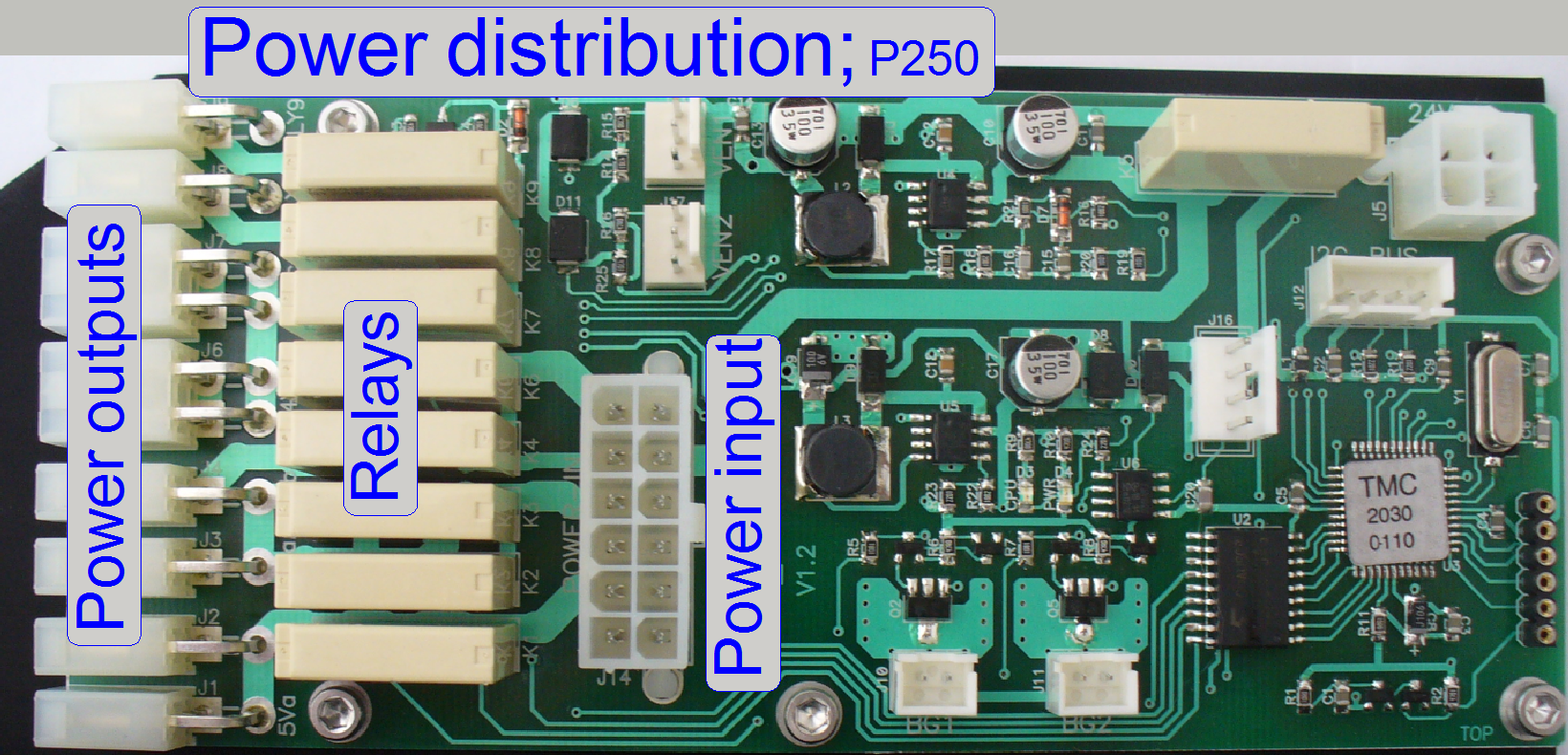 The power outputs can be
switched by software; so momentarily unused units can be switched off, like the
brightfield camera during fluorescent scan or any emergency event occurred.
The power outputs can be
switched by software; so momentarily unused units can be switched off, like the
brightfield camera during fluorescent scan or any emergency event occurred.
The outputs are switched by
the use of relays.
The communication between software and the power distribution board is
realized with the control bus connector; this is connected to the USB
controller and is used to switch on / off the power outputs and to transfer
status information to the USB-controller.
The temperature sensor input controls the fan outputs (Fan1 and Fan2)
directly, without any scan software control, bat the temperature value and the
fan speed can be read from the software; see also the service program, Low
level service, power supply. The fan speed is controlled via the PIC on this
switch board, depending on the sensed temperature value.
Mounting of the power
distribution and switch board
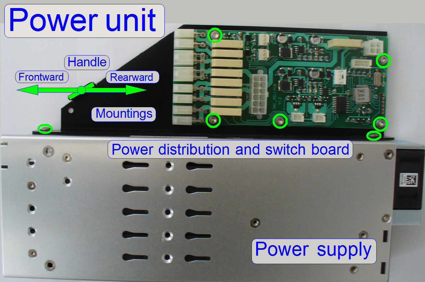
· By removing the appropriate
bolts, the switchboard and / or its holder can be removed.
· The handle is used
to shift the entire Power unit in its mounting rail.
Enable or disable of the switch board
For technical enhancements and upgrades, the type of the entire “Power
distribution and switch board” can be defined or the board might be disabled.
The relevant parameter and value is found in the section [Microscope] of the file “MicroscopeConfiguration.ini”.
To enable the switch board:
PowerSwitchBoardType=PowerSwitchBoard_Type1
Actually, the most recent
“Type1” is used.
To disable the switch board:
PowerSwitchBoardType=PowerSwitchBoard_None
Usually, the board is enabled.
If the entire “Power distribution and switch board” is disabled, the
power supply for the cameras and all other connected units is disabled; the scanner
will not start correctly or the powering of the appropriate units have to be
realized otherwise; e.g. with external power supplies.
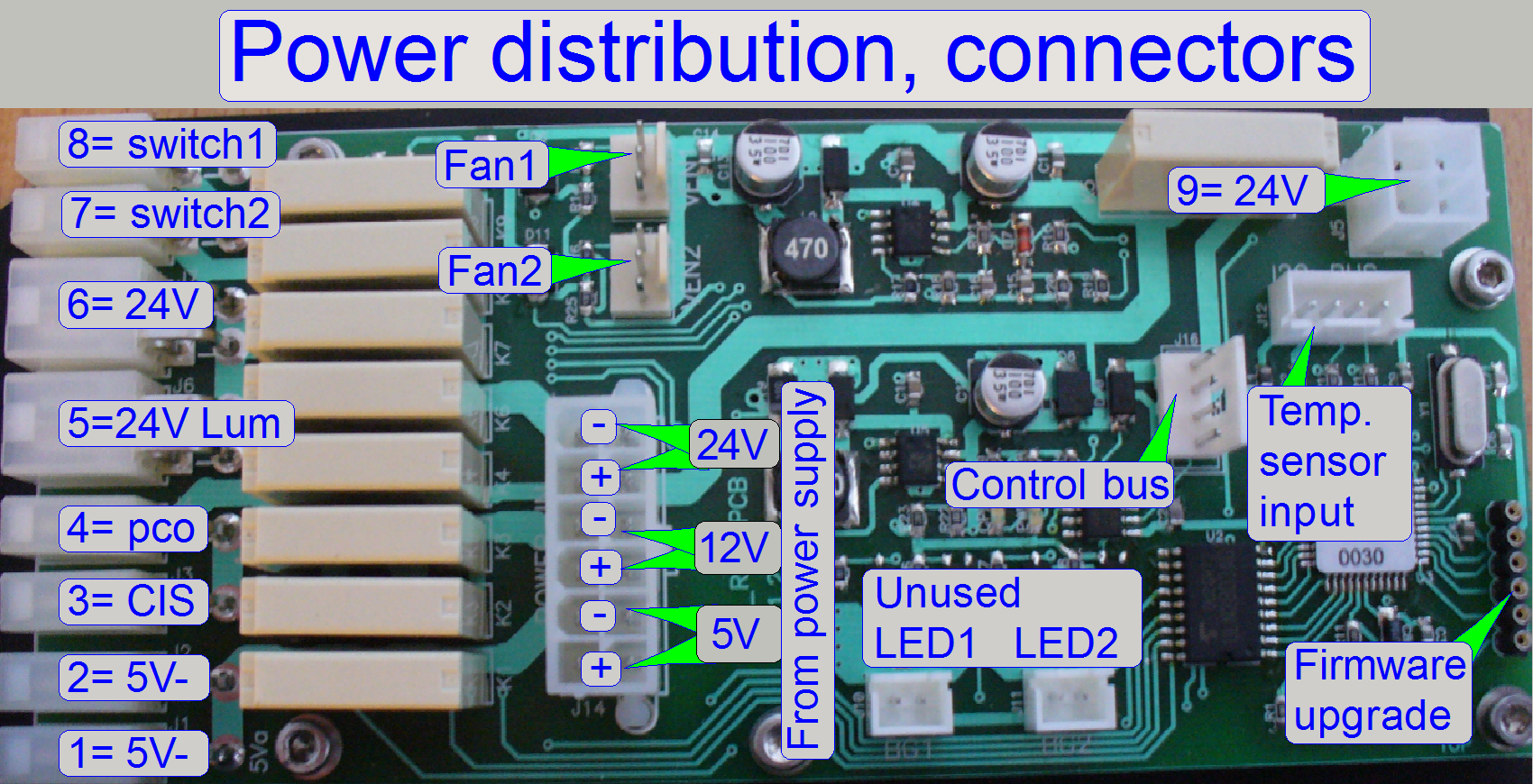
1= reserve 5V- output
2= reserve 5V- output
3= Power output 12V- for the
CIS brightfield scan camera
4= Power output 12V- for the
PCO edge fluorescent scan camera
5= Power output 24V- switches
the current amplifier.
7= reserve switch1
8= reserve switch2
9= reserve 24V- output
5V= Power input from the TDK-Lambda power supply
12V= Power input from the TDK-Lambda power supply
24V= Power input from the TDK-Lambda power supply
The switched outputs are ground independent (the minus pole is not
connected to GND) so each voltage has a plus (+) and a minus (-) pole.
Connectors
Fan1 and Fan2
Via these connectors the fans in the rear wall are connected.
Both fans are handled in parallel mode so any fan can be connected to
any connector; the fan connection is interchangeable.
Temperature
sensor input
The temperature sensor input is an I2C bus input and the
temperature sensors are connected with the cable TMJ-1, TMJ-2.
Temperature
sensor, fan and fan control
 Because the
cameras needs cooling (their temperature must not exceed 60º C (140º F)),
temperature sensing and active cooling of the scanner is required.
Because the
cameras needs cooling (their temperature must not exceed 60º C (140º F)),
temperature sensing and active cooling of the scanner is required.
The sensed temperature value is used to control the speed of the fans
directly; without any interaction of the scan software “SlideScanner.exe”.
In the service program, the sensed temperature is shown in [ºC],
the fan speed is shown in a value between 1 and 255; 255 is the full speed of
the fan.
- The sensed
temperature value and the fan speed can be read with the service program
any time.
If the field “Error” is different from zero, a HW error exists in the
temperature sensor and fan control electronics.
Error
codes
16 Fan error; the spinning speed of one or both
fans is too slow; check and clean the dust filters
or the fan blades moving too strong; they have too much resistance in the
bearing.
32 Fan error; the blades of one or both fans
are not spinning; check cabling, connection; try to rotate the fan blades
manually; check for any mechanical reason also.
64 The temperature of 60º C (140º F)
reached; check and clean the dust filters of the fans; check the fans
connection and the movement of the blades also.
128 Scanner overheated; the relays are
switching off; the power to the connected units is interrupted; the temperature
reached 70º C.
· Because the error
bits are arranged in a byte, other values are possible if more errors existing
at the same time; e.g. 96= 64 + 32.
· If the units are
switched off by overheating, the scan software SlideScanner.exe shows the error
message “Error
occurred” and stops working.
 The temperature inside the
P250 is sensed via two, a left and a right sided temperature sensor by the help
of the PIC on the switch board.
The temperature inside the
P250 is sensed via two, a left and a right sided temperature sensor by the help
of the PIC on the switch board.
Probably errors may be:
- 1 or both
temperature sensors are not connected; any wire is broken or has no
contact.
- Sensor is
defective.
- Power
distribution and switch board is defective.
- Identical
address of both sensors (after exchange).
![]() “Temperature sensor”
and Construction of the P250 “Base plate
and housing truss”.
“Temperature sensor”
and Construction of the P250 “Base plate
and housing truss”.
 Both fans are
handled in parallel mode; but the spinning of the blades of each fan is also recognized
by the PIC separately; there must not be a significant difference between the
fans spinning speed.
Both fans are
handled in parallel mode; but the spinning of the blades of each fan is also recognized
by the PIC separately; there must not be a significant difference between the
fans spinning speed.
Probably errors may be:
- The signal of
any fan spinning sensor (situated inside the fan) is not recognized by the
fan control logic, because the fan is not or not well connected; the fan
blades does not rotate (any mechanical or cabling reason) or the fan is
defective.
- If the fan
speed is too slow please check and clean the dust and particle
filters or the fan blades moving too strong; they have too much
resistance in the bearing.
- The power
distribution and switch board is defective.
![]() “The
fan”
“The
fan”

To clean the dust and particle filter please
Current amplifier for the
Lumencor SPECTRA light engine®
 The current (power)
amplifier is realized by the use of a relay; it is switched on or off by the
output 5 of the “Power distribution and switch board”.
The current (power)
amplifier is realized by the use of a relay; it is switched on or off by the
output 5 of the “Power distribution and switch board”.
Because the relay on the “Power distribution and switch board” output 5
can not handle the required current of 5A DC a second relay is used.
The relay is found in the common housing of the power supply and the
“Power distribution and switch board”; see also: Construction of the P250 “Base plate and housing truss”.
 The USB controller
connects, supplies and controls all the addressable units and outputs; these
are:
The USB controller
connects, supplies and controls all the addressable units and outputs; these
are:
- X-Y-Z-ND-motor and
Flash light control electronics
- DC-Controller
- Objective changer unit (OC)
- Turret unit (stepper motor)
- Camera changer unit (CC)
- Power
distribution & switch board.
- Brightfield preview illumination
- Barcode illumination
- The USB
controller gets its +-24V power directly via the cable PWJ-1 from the
tdk lambda
OEM power supply.
Control, cables and connections
The USB controller receives the command for the units from the program
SlideScanner.exe (the scan program) or the SlideScannerService.exe (the service program) via the USB
control port of the PC and the USB cable.
All units contain separate electronics and are connected via a bus
system. To differentiate the units, connected to the USB controller, some
stepper motor electronics and the unit-controller as well has an address. Each
data transfer starts with the specified address for the unit and is listen by
all units at the same time, but only this unit receives the message, which
internal address and the message address is identical. The stepper motor
electronics can receive commands (number of steps to go and direction) and can
send status information (desired position reached and the status of the sensors
Home1 and Home2). The status information
is sent via the USB cable to the software, hereby the address of the unit is
used also.
With this solution it is possible to change the “Hirschmann” connection
with another “Hirschmann” cable (e.g. for fault detection) without any risk or
functional restrictions. The label of the cable for digital electronics has no
reason in functionality; it differentiates the cables from each other instead,
because some cables are shorter than others.
Important
The construction of the controller powering on the board
does allow the drive of maximal 3 stepper motors at the same time!
· Please take this into account, if you are working with
the service program and the batch test program module!
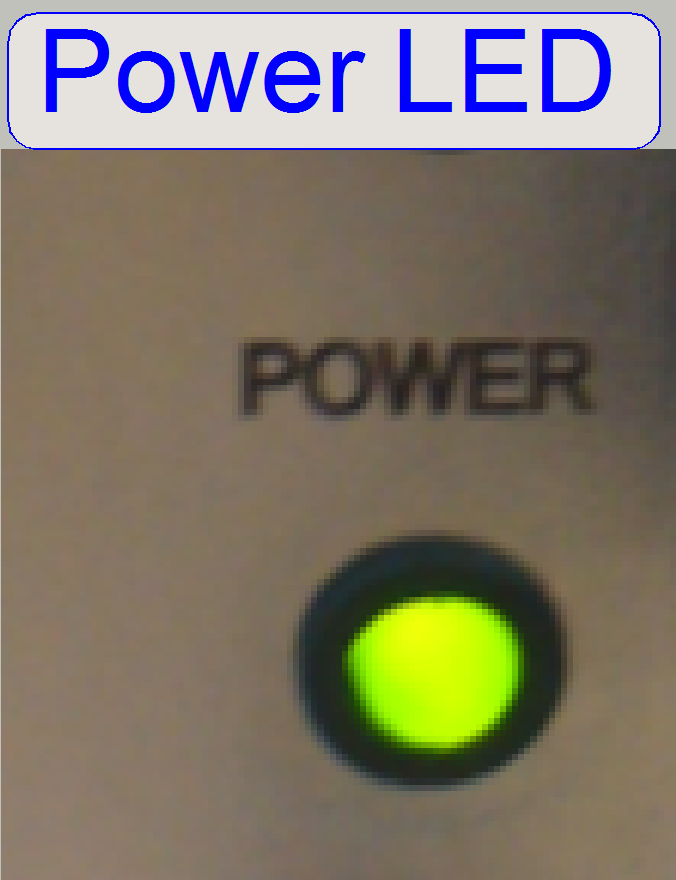 Power LED
The power LED is lighting if the
power is supplied to the Pannoramic scanner (the power cable is connected; the
power supply and the emergency switch are switched on).
If the power LED is not lighting
- Check the mains power in the connector outlet.
- Check the power
cable and its
right connection.
- Check the mains
power switch state on
the rear.
- Check the emergency switch state.
- Check the fuses.
- Check the conductivity of components “Power input and
mains switch”
- Check the output voltages of the power
supply.
- The USB-controller gets the
24V- from the power supply?
If the power LED is flashing
If there is a shortcut inside the
scanner, the power supply is switched off by overload; every 200 ms the power supply
will switch on itself and tries to supply the output voltages. This behavior
makes slightly flashing the power LED; the fans may rotate.
- Switch off the mains
power of the
power supply and measure with the
ohmmeter the
resistance between the positive and the negative pole of the output
voltages 24V, 12V and 5V of the power supply “tdk
Lambda”. (Do not
measure the +pole in relation to ground, because the voltages are ground
independent!)
- If the resistance is 1 or 2ohms only or nearly 0
ohm, the defective (shortcut) output is found.
- Remove the power output connectors of the “Power
distribution and switch board” and switch on the power supply again and
measure any output voltage of the power supply.
- Remove the Power input connector of the “Power
distribution and switch board” and switch on the power supply again and
measure any output voltage of the power supply.
- Remove the power output connections of +24V of
the power supply “tdk
Lambda” and
switch on the power supply again and measure any output voltage of the
power supply.
- Remove the power output connections of +12V of
the power supply “tdk Lambda” and switch on the power supply again and
measure any output voltage of the power supply.
- Remove the power output connections of +5V of the
power supply “tdk Lambda” and switch on the power supply again and measure
any output voltage of the power supply.
If the shortcut disappeared, measure
the resistance of the disconnected paths / wires with the ohmmeter against the
negative pole of the appropriate output voltage or reconnect the appropriate
connections singly, separately to find the faulty path.
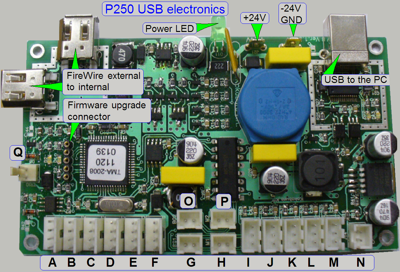 Nominal “wire to board” connector positions:
B = PCJ-1; Power distribution and switch board
C = DCJ-1; DC-Controller
D = DOJ-1; Objective changer
E = STJ-5; Camera changer
F = CUJ-1; X-Y-Z-ND-motor and Flash control
G = BGJ-2; Barcode illumination
H = Reserve
I = Reserve
J = Reserve
L = Reserve
M = Reserve
N = Reserve
O = BGJ-1; brightfield preview (background) illumination
P = Reserve
Q = Trigger connector for the camera Sony DFW-X710
- The USB
controller gets its +-24V power directly from the tdk lambda
OEM power supply; the minus pole (-) is connected to the pin, named as
GND!
The addressable units are connected via the “Hirschmann” connector. The
cable contains the power supply for the unit (24V-) and the serial bus (I2 C). Via the
serial bus the connected units are addressed, receive command and control
information and returns status information.
Each connected unit contains a local power supply to create further,
required voltages.
Cabling of addressable units
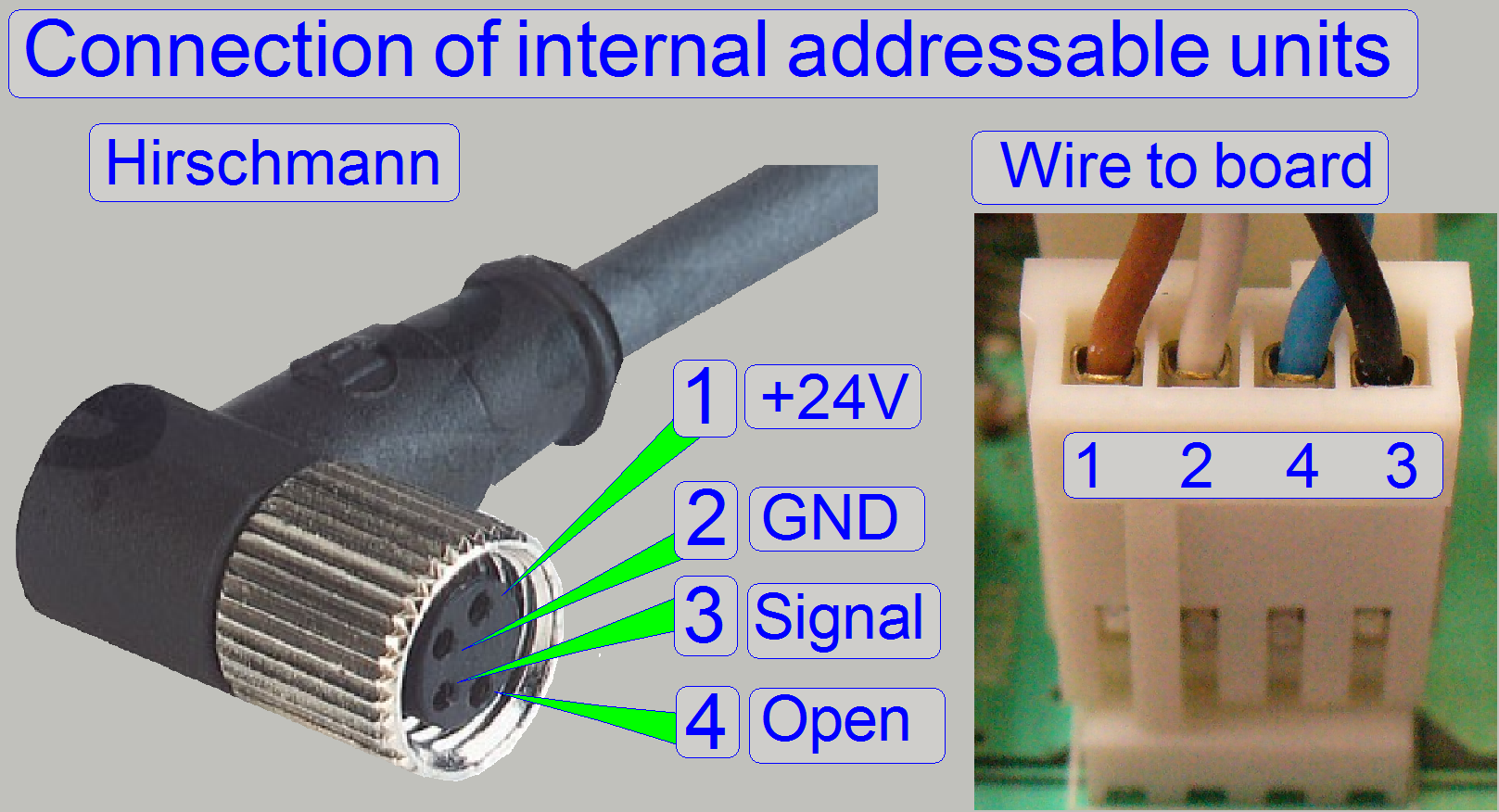 The addressable units are
connected with the “Hirschmann” connector (except the Power distribution &
switch board); the connection is secured with a knurled nut. On the other end
of the cable a “wire to board” connector is used.
The addressable units are
connected with the “Hirschmann” connector (except the Power distribution &
switch board); the connection is secured with a knurled nut. On the other end
of the cable a “wire to board” connector is used.
Important
Please do not use pliers to loosen or tighten the cable header lock nut.
If there is too much force used on the connectors, the soldering of the
connector may be destroyed and broken and the appropriate motor or unit will
not work.
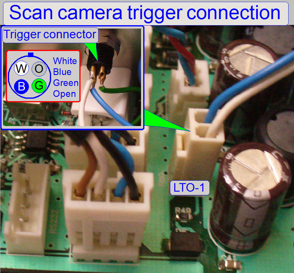 The trigger connector is used
for the
Sony camera or the Grashopper camera.
The trigger connector is used
for the
Sony camera or the Grashopper camera.
If the camera is not recognized after changing the USB controller box,
please check the correct cabling and the connections as shown on the right.
for the camera Sony DFW-X710
 On the right side
of the rear the USB controller box is situated; it is covered by the right side
corner cover.
On the right side
of the rear the USB controller box is situated; it is covered by the right side
corner cover.
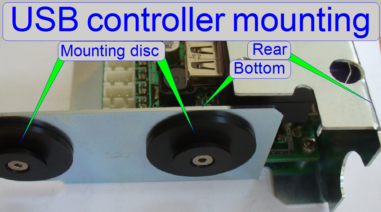
On the bottom of the USB controller box a mounting rail is situated in
which the mounting discs of the USB controller unit are shifted in.
Important
Please shift the entire USB controller unit only
frontward or backward.
· If the USB
controller will be inclined sideward or upward during the removal or insert
procedure, the plastic mounting discs will be destroyed!
Remove the USB controller
- Switch off
the scanner.
- Disconnect
all USB controller cables (on the rear part).
- Remove the
right corner cover.
- Pull the
entire USB controller unit evenly and straightly backward; otherwise, by
moving it up- downward or left / right the mounting discs may be damaged
or destroyed!
- Disconnect
the cables if necessary.
 Remove the controller board
- Disconnect
all the internal cables and wires.
- Remove the
mounting bolts, situated in the corners of the PCB.
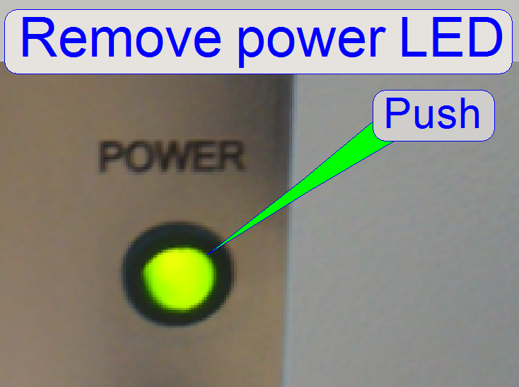
- Push the
power LED carefully out of its socked from the rear; then the PCB can be
removed easily.
Mount the controller board
- Connect the
wires +24V and -24V to GND of the board first to the appropriate
connectors.
- Fit and push
the power LED into its socked of the rear.
- Fit the PCB
corner drillings to the PCB standoffs and mount the PCB.
- Connect all
the internal cables as shown above.
Mount the USB controller
- Fit the
mounting discs into the mounting rail on the bottom of the USB controller
box and shift the unit straightly frontward until the unit stops.
- Mount the
right corner cover.
- Connect the
interface cables.
- Switch on the
power supply.
|
Addresses of scanner
units |
||
|
Unit |
Address |
Type |
|
X-Y-Z
control |
00 |
C_P |
|
USB-controller |
01 |
All |
|
DC-controller |
02 |
P_S_M_D
|
|
X-motor |
03 |
S_M_D |
|
Y-motor |
04 |
S_M_D |
|
Z-motor |
05 |
S_M_D |
|
Turret
unit |
06 |
S_M_P |
|
Tray
loader motor |
07 |
M_C |
|
Slide
loader motor |
08 |
M_C |
|
Objective
changer |
09 |
C_P_S_M
|
|
Camera
changer |
10 |
P |
|
RGB
illumination |
11 |
C |
|
Not
used |
12 |
----- |
|
Immersion
liquid unit |
13 |
C |
|
Mechanical
shutter |
14 |
C |
|
Switch
board |
15 |
C_P |
|
Legend:
C=Confocal; P=P250; S=SCAN; M= |
||
The addresses are used by the scan program and the
service program to select the unit; these addresses are programmed into the
specified unit and can be changed via special
software only. It is important, that none of these addresses should
exist twice inside of one Pannoramic scanner, otherwise command and status
mismatch occurs.
If data transfer is in progress, all addressable units
listen to the address of the data stream.
If the address of the unit is identical with the
address of the data stream, the addressed unit is found and this receives the
information.
 The
EEPROM stores the scanner specific parameters and these are collected in the
files MicroscopeConfiguration.ini and
MicroscopeSettings.ini. To ensure an always proper functioning of the scanner,
the content of the EEPROM should be updated after adjustments are done or units
are exchanged and parameter values are modified. The EEPROM is a part of the
USB controllers PCB.
The
EEPROM stores the scanner specific parameters and these are collected in the
files MicroscopeConfiguration.ini and
MicroscopeSettings.ini. To ensure an always proper functioning of the scanner,
the content of the EEPROM should be updated after adjustments are done or units
are exchanged and parameter values are modified. The EEPROM is a part of the
USB controllers PCB.
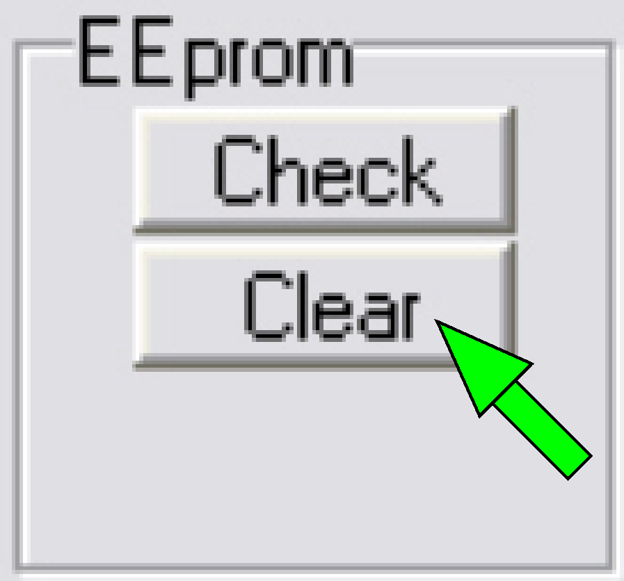
· To update the
content, the EEPROM should be cleared with the service program.
· If the scan
software is started and the EEPROM is empty, the content of the appropriate
*.ini files will be written automatically from the appropriate folder of the
HDD into the EEPROM.
1.
 Start
the program “SlideScannerService.exe”.
Start
the program “SlideScannerService.exe”.
2.
Click in the field
“Clear EEPROM” of the selector menu.
3.
Answer the dialogue with “Yes”; then the
EEPROM is cleared.
4.
Exit the service program with “EXIT”
5.
Start the program SlideScanner.exe; the
*.ini-files will be automatically saved from the appropriate HDD folder into
the EEPROM during startup of the program.
Compressed content of the EEPROM (P250, SCAN,
The compression of the EEPROM content is required since the software
version 1.16, because there are newly implemented parameters and the capacity of
the EEPROM is limited to be 2kB.
· By compressing the
content, memory space is freed up.
In systems, delivered with the version 1.16 the modified handling of the
EEPROM content will not be noticed by the user; the files
“MicroscopeConfiguration.ini” and “MicroscopeSettings.ini” staying on the HDD
in uncompressed form.
· If the EEPROM
content is written, the files “MicroscopeConfiguration.ini” and
“MicroscopeSettings.ini” will be compressed before these are stored in the
EEPROM.
· If the EEPROM is
read, the content will be uncompressed before it is stored as file
“MicroscopeConfiguration.ini” and “MicroscopeSettings.ini” on the HDD.
If an upgrade is made (from the version 1.15 to the version 1.16) the
content in the EEPROM is uncompressed but the version 1.16 expects a compressed
content; therefore:
Before you are installing the software version 1.16
· Make sure; the
content of the files “MicroscopeConfiguration.ini” and “MicroscopeSettings.ini”
is the most recent content on the HDD.
· Save these files
to a save place also
Install the software version 1.16
· Start the program
“SlideScanner.exe” first time.
· The compression of
the EEPROM content will be done automatically.
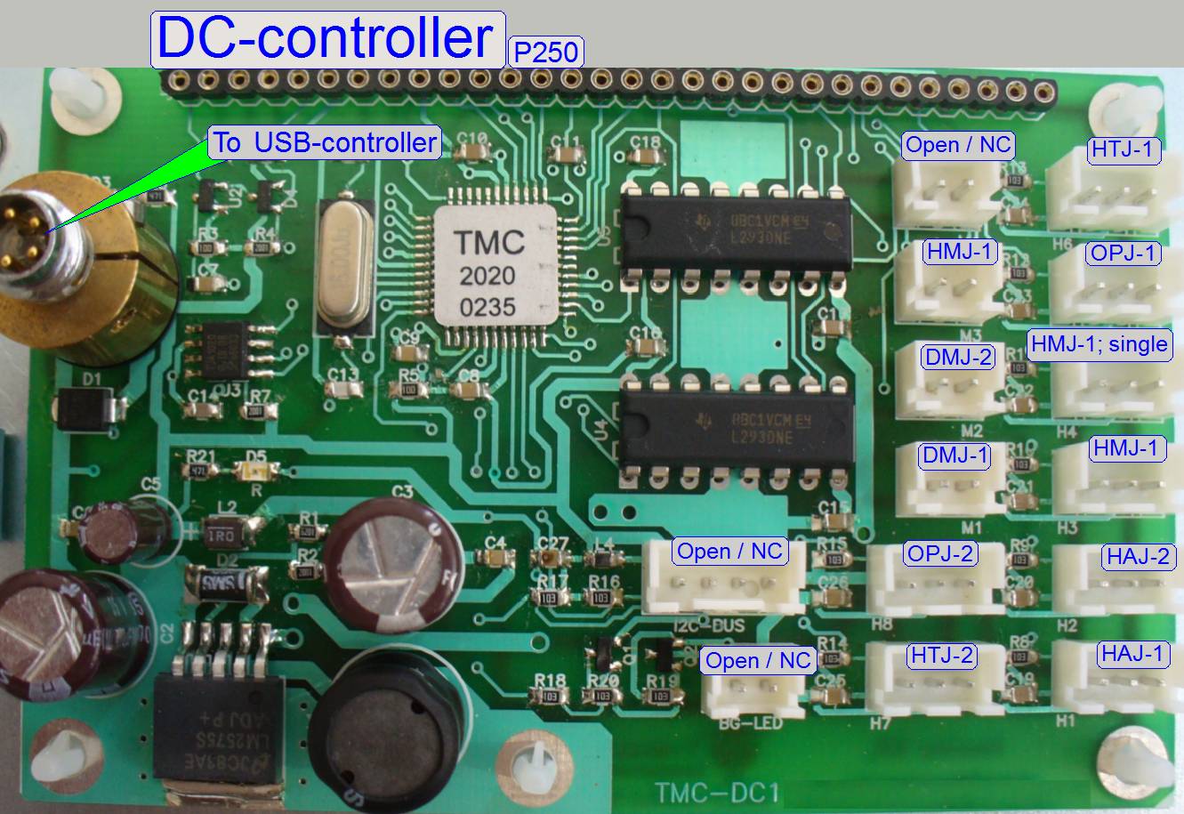
The DC electronics box is mounted onto the magazine unit from beneath.
The DC-controller switches the DC-motors on or off;
collects the status information of the connected sensors and transmits this to
the USB-controller.
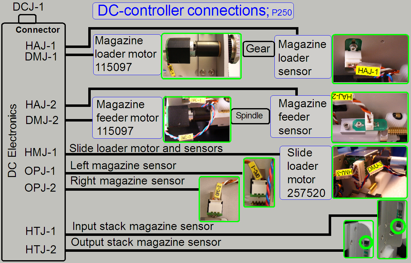
To prevent the DC-motors from overload if hardware jamming occurs, all
commands, starting the DC motors have a time out (started by the scan
software). Normally, the motor is stopped with the sensor action before the time
is run out. If the sensor action is missed (jamming occurred) the time out
event will switch off the motor.
X-Y-Z-ND-motor and Flash
light control
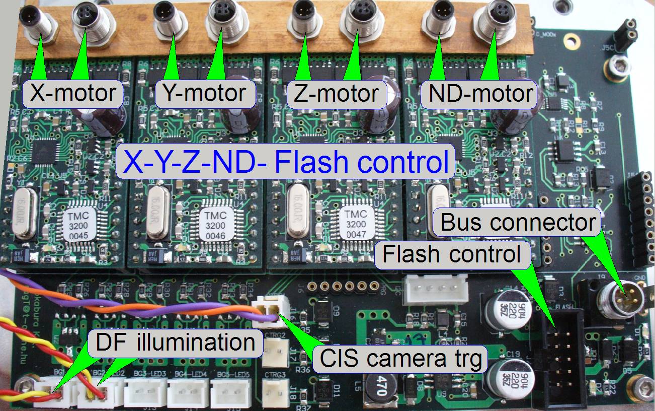 Because in the P250 the
ND-motor is additionally implemented, the Flash light control has to be
resolved and the focus motor is of a different type, a new electronics box was
implemented.
Because in the P250 the
ND-motor is additionally implemented, the Flash light control has to be
resolved and the focus motor is of a different type, a new electronics box was
implemented.
The unit realizes the control, connections and interfacing of the following
units:
- X-motor
- Y-motor
- Z-motor
(focus)
- ND-motor
- Flash light
control for brightfield scan
- Trigger
connection of the
CIS-camera
- Darkfield illumination
- The power
supply and the control of the addressable unit are realized with the
“Hirschmann” connector (Bus connector).
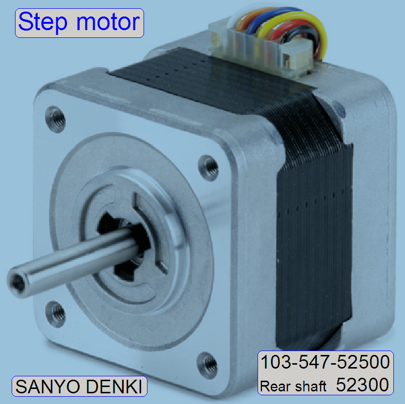
- The X-, Y-,
Z- and ND-stepper motor control electronics is realized with the
appropriate module; these motors itself does not contain control
electronics.
- The motor
modules are all from the same type and are interchangeable without address
modifying.
Flash light control
The arc frequency
of the Flash light source is controlled via the software.
The connector
“CIS-camera trg” is software controlled and defines the shutter time and pulse
width for the CIS-camera.
Darkfield illumination connector
·
The two connectors “DF illumination” provide the power
for the darkfield illumination and are interchangeable; the intensity can not
be affected.
 Important
Please do not use pliers to
loosen or tighten the cable header lock nuts. If there is too much force used
on the connectors, the soldering of the connector may be destroyed or broken
and the appropriate motor will not work or may working very noisy.
The wires of the appropriate
stepper motor as well as the wires of the sensors are directly connected to the
electronics via the motor cable headers.
The construction of the
connectors does not allow an interchanging of the two cables to each other, but
the motor can be connected to another module; e.g. for fault detection.
·
The sensors Home1 and Home2 are also connected via the
motor headers.
Important
· For test purposes and fault detection, the motor cable
header pair may be connected to another motor output; e.g. the X-motor headers
are connected to the Y-motor output.
· In this example, the service program Y-direction will
be used to move the X-stage!!
· Before SlideScanner.exe will be started, the motor
cable headers have to be connected to their original, correct motor connection!

About
basics, theory and principles please refer to:
http://www.solarbotics.net/library/pdflib/pdf/motorbas.pdf
Stepper
motor basics (stored)
Drive circuit basics (stored)
Stepper motor and driver (stored)
External
recirculation diodes (stored)
Stepper motor
driving (stored)
Stepper motors 2011 (stored)
Background
(preview) brightfield illumination
 The preview
illumination consists of 6 LED’s and is
used to illuminate the scannable part of the slide and makes so the sample
visible for the preview camera.
The preview
illumination consists of 6 LED’s and is
used to illuminate the scannable part of the slide and makes so the sample
visible for the preview camera.
The preview illumination exists as a 0R version only.
The output for the preview illumination is driven by a
current generator. The intensity of the backlight can be adjusted in the range
between 1 and 255 (maximum) in the service program only, 0 means the backlight
is switched off. The parameter is removed in the software version 1.15 from the
file “MicroscopeConfiguration.ini” section [PreviewAndBarcodeScanning].
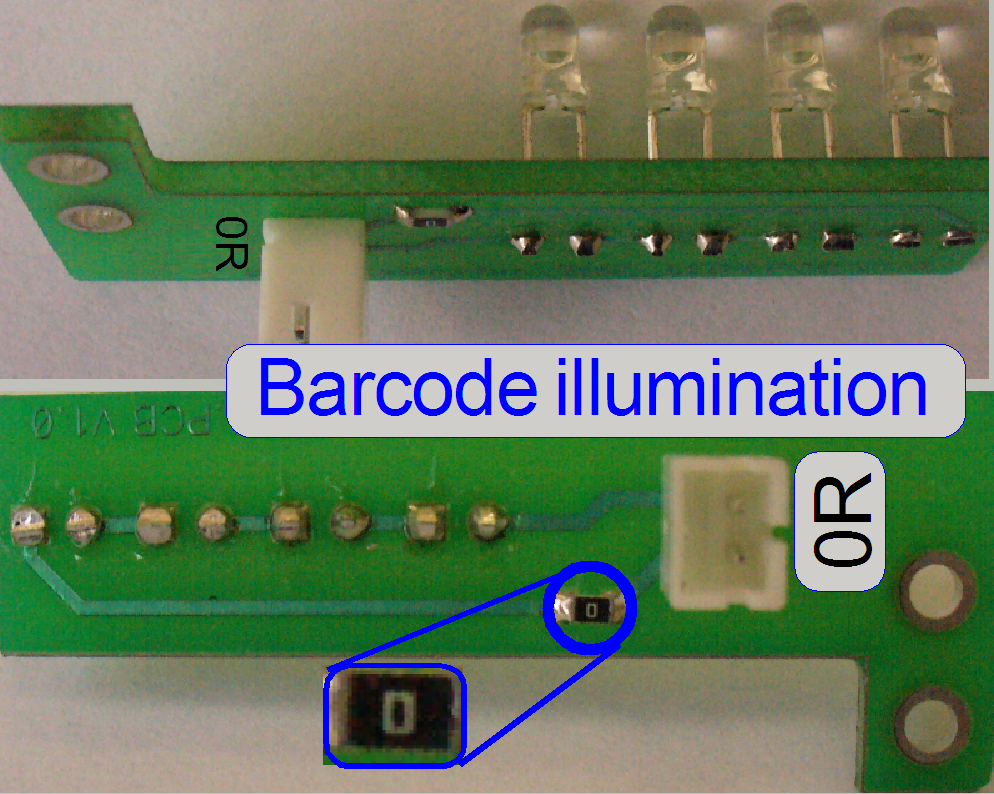 The barcode
illumination consists of four LED’s and is
used to illuminate the barcode area of the slide and makes so the barcode
visible for the preview camera.
The barcode
illumination consists of four LED’s and is
used to illuminate the barcode area of the slide and makes so the barcode
visible for the preview camera.
The barcode illumination exists as a 0R version only.
The output for the preview illumination is driven by a current generator. The
intensity of the backlight can be adjusted in the range between 1 and 255
(maximum) in the service program only, 0 means the backlight is switched off. The
parameter is removed in the software version 1.15 from the file
“MicroscopeConfiguration.ini” section [PreviewAndBarcodeScanning].
Optical
sensors OPJ-1 and 2
(left and right magazine sensor)
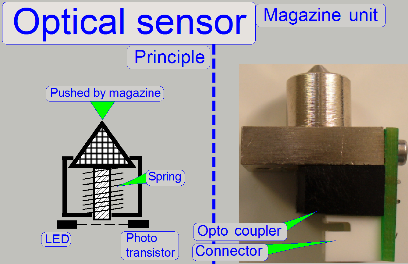 If the
optical sensor is pushed by the magazine, the light path between LED and photo
transistor will be broken by a pin. This action is recognized by the software.
If the
optical sensor is pushed by the magazine, the light path between LED and photo
transistor will be broken by a pin. This action is recognized by the software.
The sensors are
situated on the
magazine feeder channel bottom plate and their positions are fixed.
- The sensors do not need adjustment.
- The sensors should be kept clean. Because the action path is very
short, even small glass shards or dust is able to prevent the sensor from
correct switching.
![]() “How to exchange the sensors OPX_1_2”
“How to exchange the sensors OPX_1_2”
Optical interrupter H22LOI Datasheet; stored
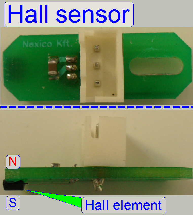 The “Magazine
Loader Sensor”, the “Magazine feeder
sensor”, the “Input stack
sensor”, the “Output
stack sensor” and the “External
home sensor” of the turret unit are
realized with Hall elements.
The “Magazine
Loader Sensor”, the “Magazine feeder
sensor”, the “Input stack
sensor”, the “Output
stack sensor” and the “External
home sensor” of the turret unit are
realized with Hall elements.
- If the south pole of a magnet is over the Hall element or the north
pole on the opposite side, the switch is closed and this state is
recognized by the software.
- If the polarity of the permanent magnet is inverted or a magnetic
field is not present, no action occurs.
- The sensors are so implemented, that the south pole of the
permanent magnet stays over the sensor surface if the action position is
reached.
The sensor position is often adjustable. For
adjustment procedures see the appropriate chapters.
- The sensor does not need maintenance.
![]() Hall sensors Wikipedia
Hall sensors Wikipedia
TLE4905L Datasheet; stored
Input and output stack sensors
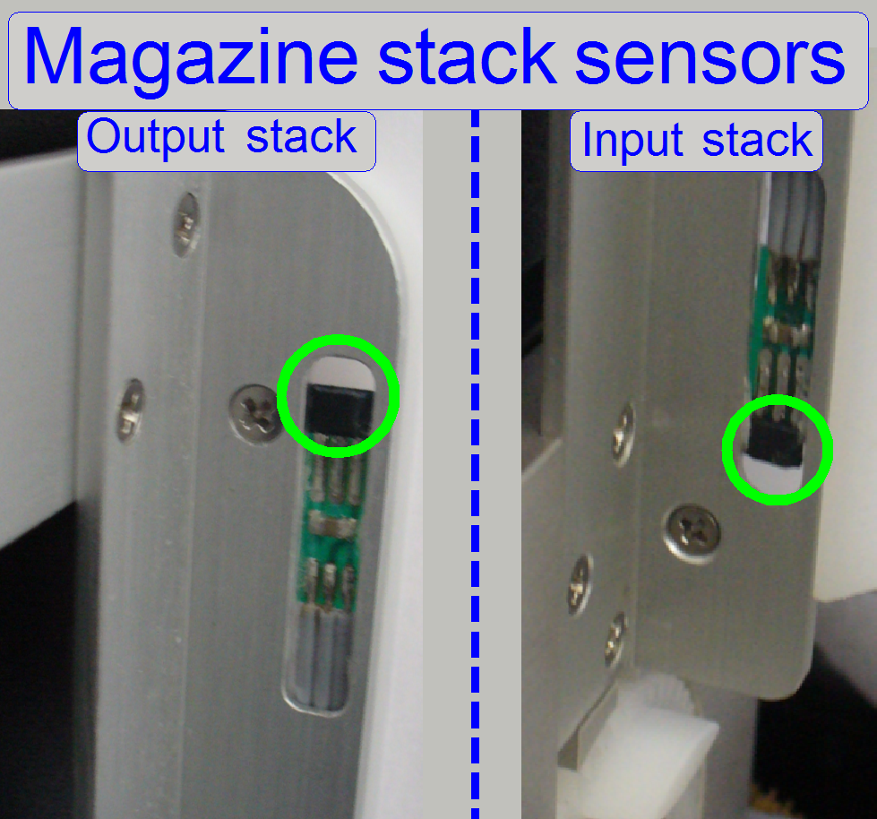
Each
magazine has a permanent magnet, implemented beside the rear upper left
corner. The sensors, implemented into the left-sided rail of the input and the
output stack are used to detect the presence of a magazine.
![]() “Stack rails”.
“Stack rails”.
The hall elements are glued in their positions. If an exchange of the
hall element has to be done, the correct position of the sensor in relation to
the acting range is important during gluing!
· Please check the
acting range with the service program
Acting range in the input
stack
· If the Magazine is
placed onto the magazine input stack wheels, the sensor “tray Hall
· If the magazine is
manually moved upward in the input stack, the signal should be inactive if a
gap of about 1mm to the input stack wheels is reached. This way the correct
insertion of the magazine will be checked also.
Acting range in the output
stack
· If 9 Magazines are placed onto
the magazine output stack wheels, the sensor “tray Hall
· If the magazine is
manually moved upward in the output stack, the signal should be inactive if a
gap of about 2mm to the previous magazine is reached.
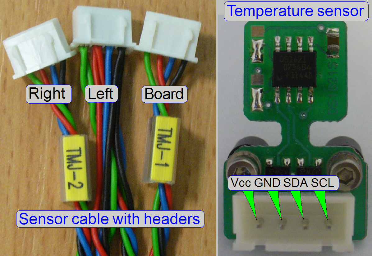
Voltage: 3.6V ~ 5.5V max
Data sheet: DS1621S
Address coding
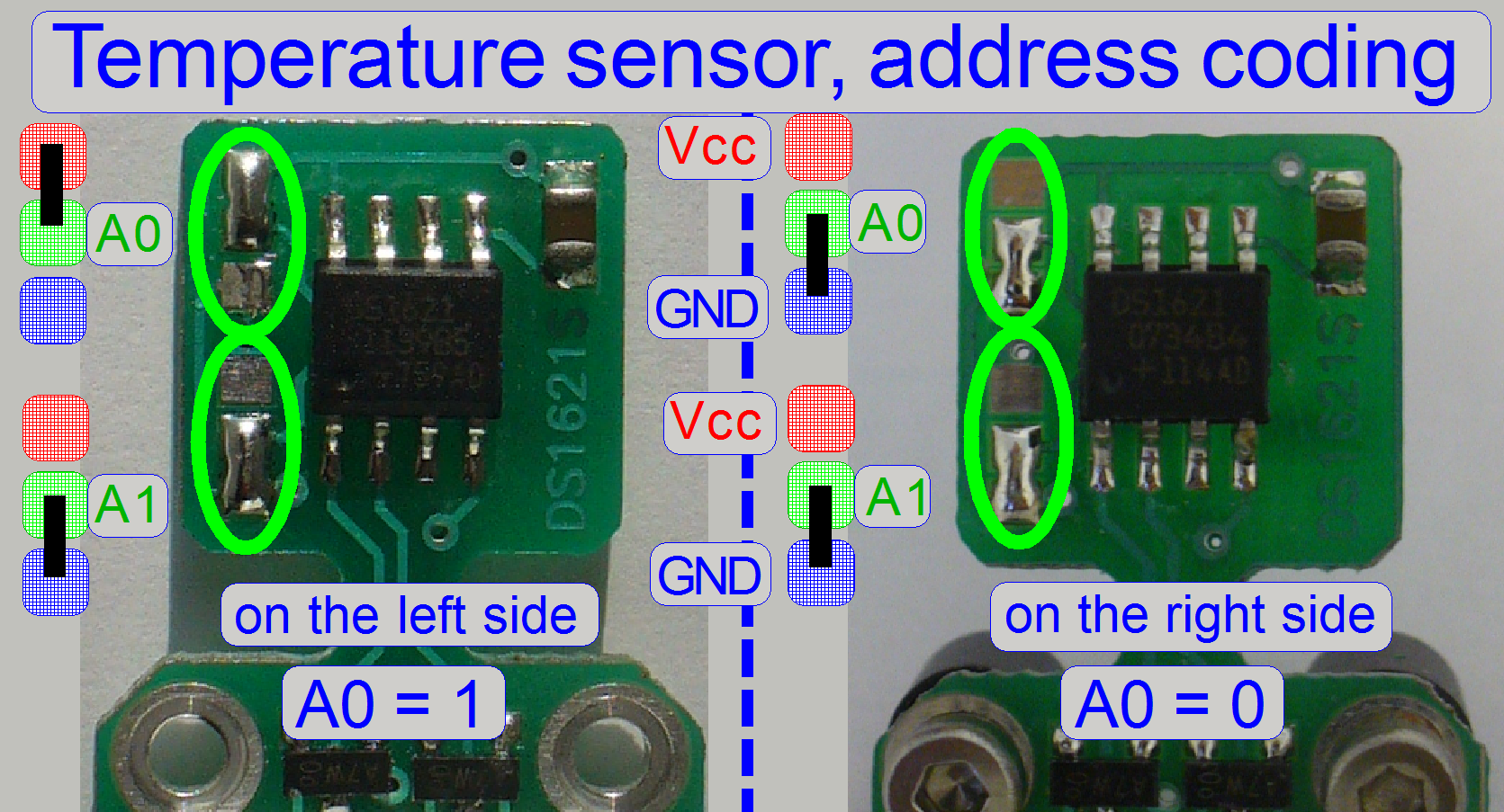
Because the sensors are used
in a bus system (I2C), the sensors are distinguished from each other
by their address. The position of the appropriate sensor address on the left
side or on the right side of the scanner is not important, but the sensors must
have a different address, otherwise, data mismatch occurs.
· The address line
A1 is always 0; it may be used in the future, in other solutions.
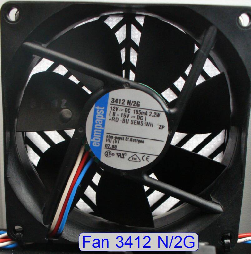 Type: ebmpapst 3412 N/2G
Power: 12V-DC 185mA; 2.2W with
spinning sensor (operating range = 8V- to 15V-
Max spin speed: 2700 rpm
By control of the fan’s voltage via the PIC on the “Power
distribution and switch board”, the spinning speed of the blades will be
affected; and so the air quantity, blown into the scanner.
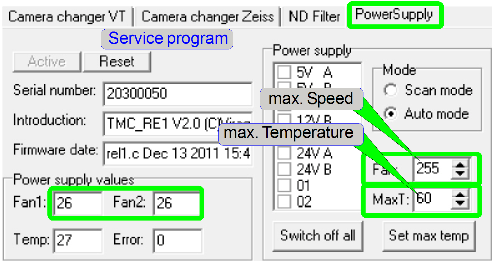
The fan speed can be calculated
by the following formula:
Fan speed = (2700 / maximal speed
value) x actual value.
In the example on the right the fan speed is:
Fan speed = (2700 / 255) x 26 = 275
rpm.
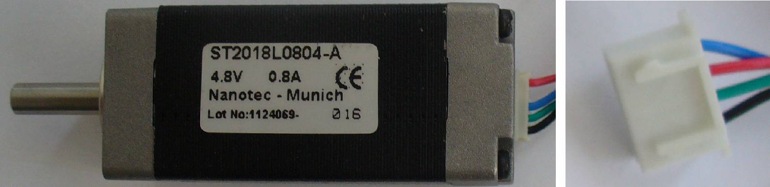
Type: Nanotec ST2018L0804-A
Power: 4.8V 0.8A
Resolution (full
steps): 200 steps/revolution
· The stepper motor
is used to rotate the ND filter disc in the ND filter housing
to adjust the brightness of the illumination for the brightfield scan
procedure.
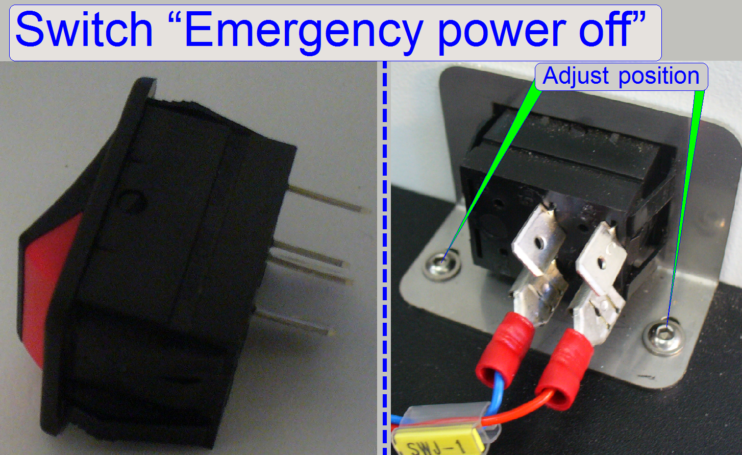
The emergency power off switch puts the power supply into standby mode if
the connectors of the cable SWJ-1 are shorted.
· The voltage is
about 15V- DC.
· The polarity of
the cable connectors is unimportant.
![]() “Emergency power off (standby)
switch”
“Emergency power off (standby)
switch”
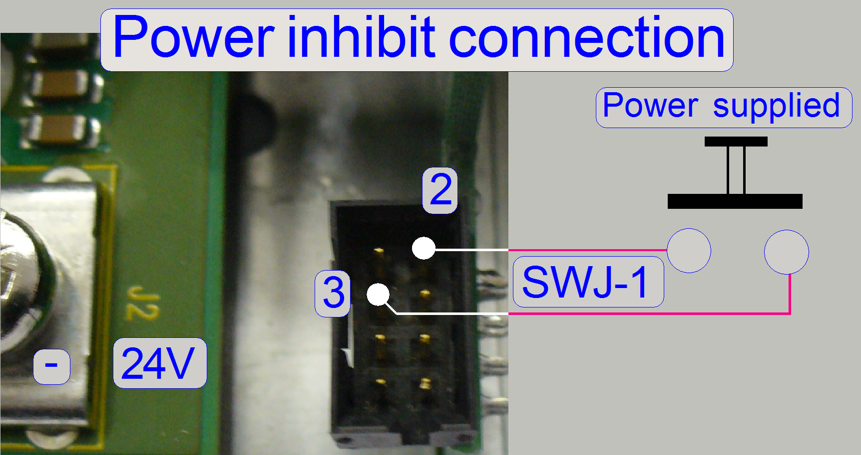
· 3 = open: Power is supplied