Housing, construction; P250
For
technicians and partly for sales managers!
Housing
The
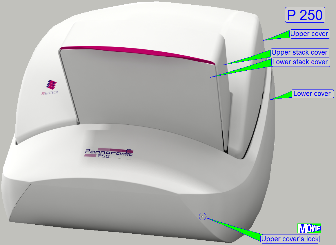
housing of the scanner P250 consists of
·
Base plate
(with 6 rubber feet and
4 handles for
movements of the scanner).
·
Lower housing with the mountings to the
housing truss and the mounting hinge to the upper cover.
·
Lock mechanism and
the opening in the lower housing to operate the lock.
·
Upper cover with the
mounting hinge to the lower cover; it can not be separated from the lower
cover.
·
Stacks’
cover upper part with the mountings to the upper cover; it can not be
separated.
·
Lower stack cover; it is mounted to the lower cover
and can not be separated.
·
Rear
cover with power input, cable entry guide for the camera and other cables
and the fan covers.
Allowed
slide dimensions are:
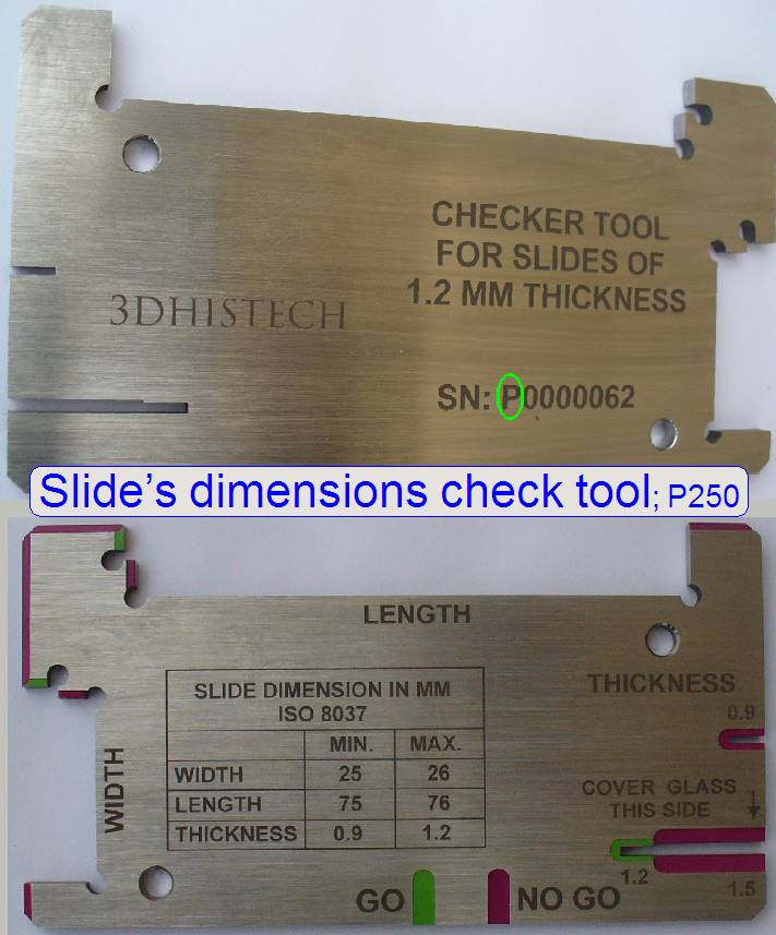
Length: 75.00
to
Width: 25.00
to
Thickness: 00.95
to
Since January
- If the first character of the serial number is an
“S” the tool is used to check the slide dimensions
of the scanners “SCAN, “
- If the first character of the serial number is a “P” the tool is used to check the
slide dimensions of the scanner “P250”.
·
Please check
the slide dimensions before filling the magazine!
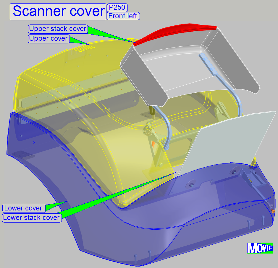
The entire housing of the scanner is
divided in functional parts.
While normal scan is in progress, all the covers are closed.
- Opening of
any cover is freely done any time, there are no software controlled lock
mechanisms.
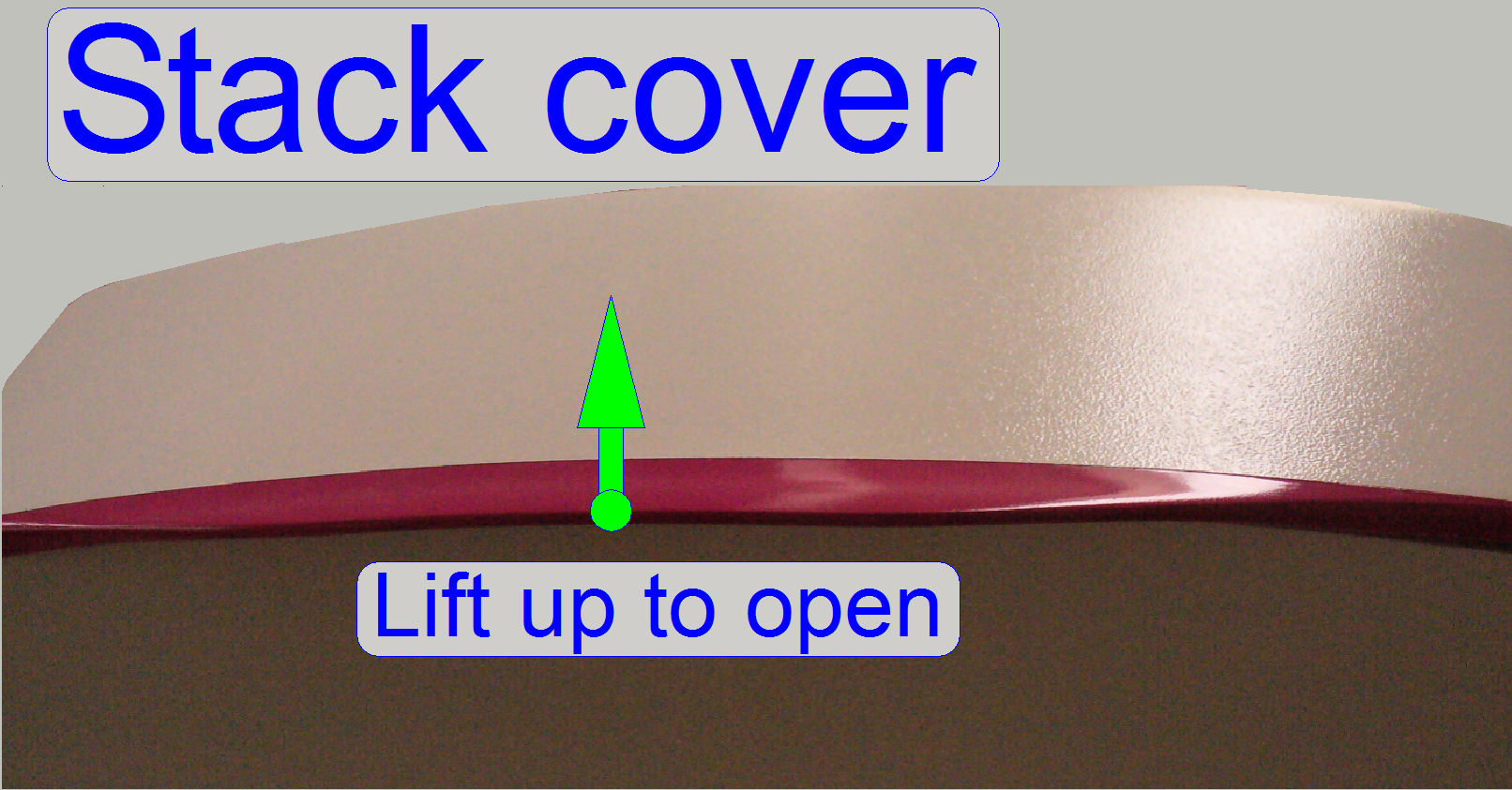
Stack cover
The stack cover is opened to insert magazines with slides into the input
stack for scanning and to remove finished magazines from the output stack.
The stack cover may be opened without stopping the scan process; but the
actual slide scan process should be finished.
- To avoid
vibrations, magazine filling actions should be done during slide insert or
removal actions or the preview capturing process of a slide.
- Thanks the
stack cover mechanics the stack cover will close itself by gravity; it can
not stay open.
Upper cover
The upper cover is opened to execute small maintenance or service
actions of any kind.
- The upper
cover is opened easily by pushing the upper covers lock button.
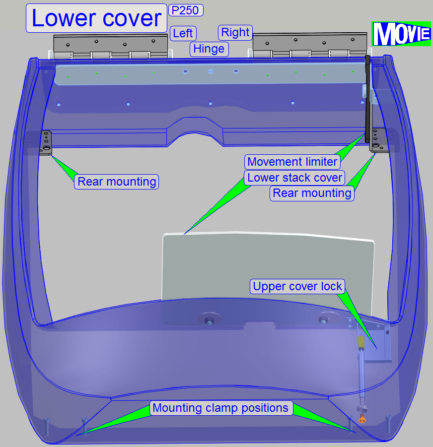
Lower cover
The lower cover is mounted to the housing truss; it is not designed for
easily opening or remove.
![]() Scanner cover mounting
Scanner cover mounting
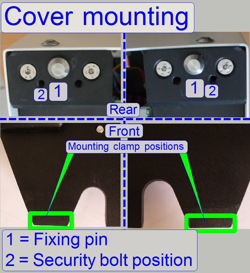
The entire cover is mounted at 4 positions, two in the front and two
positions above the rear wall.
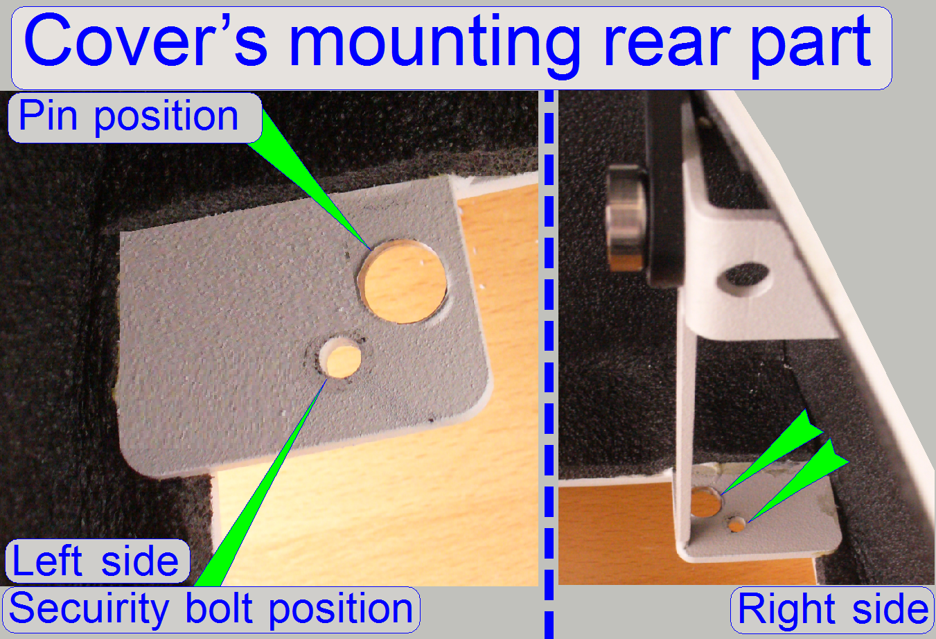
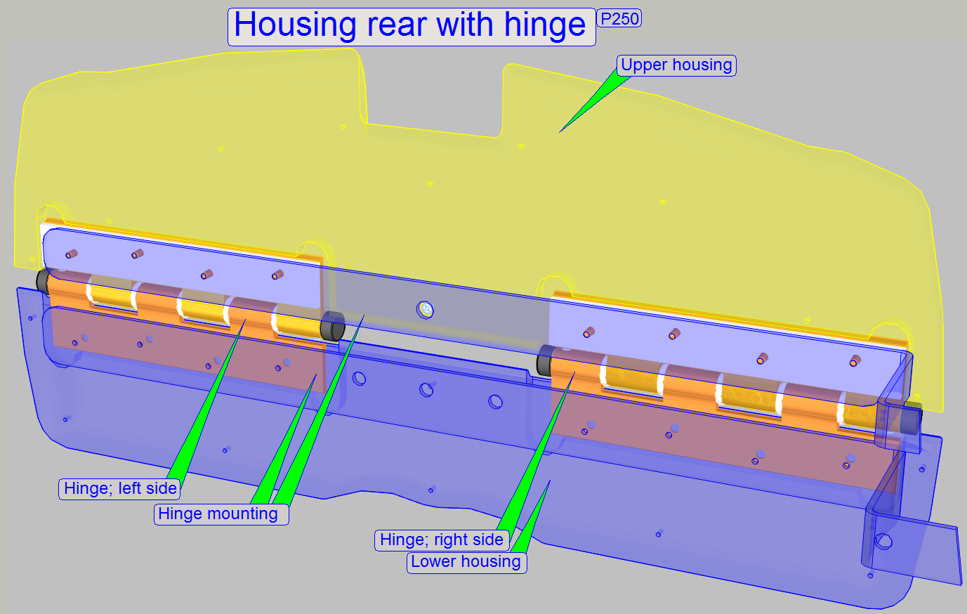
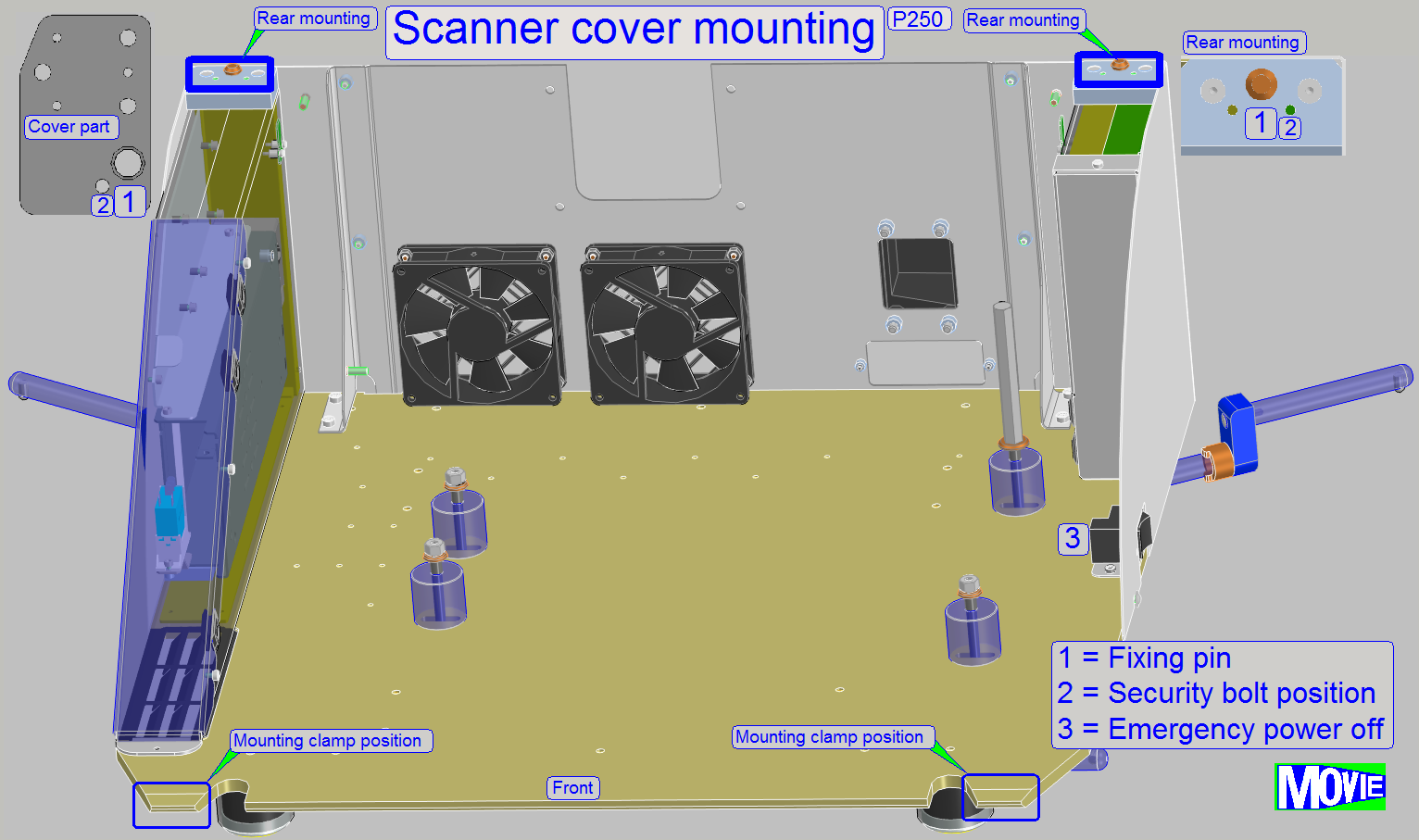 The rear mounting solution
consists of a mounting pin on the left and right side respectively; onto these
pins the drilling of the cover mounting mechanics is placed. The security bolt
fixes the cover mounting.
The rear mounting solution
consists of a mounting pin on the left and right side respectively; onto these
pins the drilling of the cover mounting mechanics is placed. The security bolt
fixes the cover mounting.
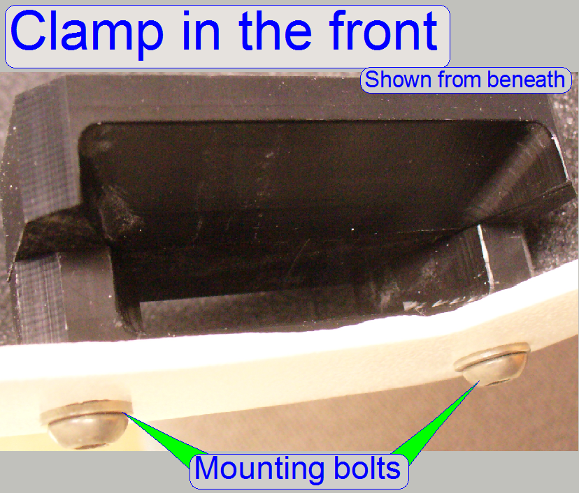 In the front of the lower cover there are two mounting
clamps, one on the left and one on the right side. These clamps are acting independently
if the lower cover is moved frontward (during removal of the cover) or if the
cover is moved backward (during mounting the cover).
In the front of the lower cover there are two mounting
clamps, one on the left and one on the right side. These clamps are acting independently
if the lower cover is moved frontward (during removal of the cover) or if the
cover is moved backward (during mounting the cover).
The entire cover is mounted at 4 positions, two in the front and two
positions above the rear wall.
The rear mounting solution consists of a mounting pin on the left and
right side respectively; onto these pins the drilling of the cover mounting
mechanics is placed. The security bolt fixes the cover mounting position.
Remove the housing
1)
Open the lock of the upper cover by using a 1.5mm hex
key wrench or an equivalent tool and open the upper cover until it stops.
2)
Remove the security bolts of the lower cover rear
mounting on the left and on the right side respectively.
3)
Remove all the camera cables of the fluorescent scan
camera (data, power and trigger).
4)
Pull the rear part of the lower cover mounting on the
rear upward about
5)
Move the entire lower cover carefully frontward, until
the clamps in the front are disconnected from the base plate mounting.
6)
Pull the lower cover upward on the front side about
7)
Now, the entire cover can be removed upward, nearly in
an angle of 30 degrees.
1)
Make sure, all the cables of the pco edge camera (for
fluorescent scan) are disconnected.
2)
Put the cover over the scanner so, that the rear part
is higher than the front part (nearly in an angle of 30 degrees) until the rear
and the front mounting positions are reached.
3)
Fit the clamps in the front part first.
4)
Fit the pins and holes on the rear part next.
5)
If all four mountings fit correctly, drive in the
security bolts.
6)
Connect the power, data and trigger cables to the
camera pco edge.
7)
Close all covers.
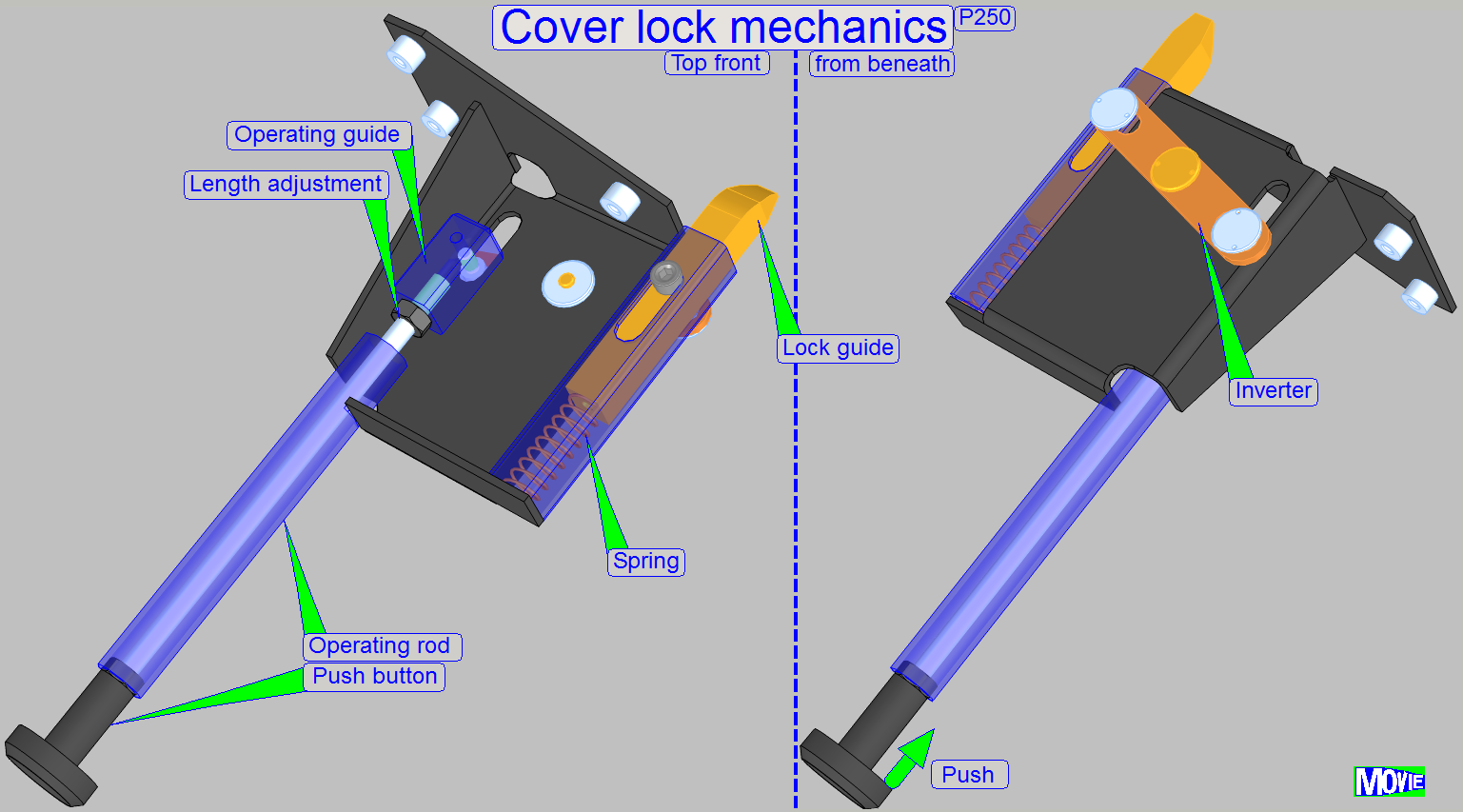 By pushing a 1.5mm hex key
wrench or an equivalent tool in thickness into the lock opening of the lower
cover the lock operating rod is pushed, via a movement inverter the lock guide
is moved backward and the lock guide keeper in the upper cover will be
released; the lock is opened.
By pushing a 1.5mm hex key
wrench or an equivalent tool in thickness into the lock opening of the lower
cover the lock operating rod is pushed, via a movement inverter the lock guide
is moved backward and the lock guide keeper in the upper cover will be
released; the lock is opened.
 The upper cover can be opened easily and quickly if
any kind of service action has to be done inside the scanner.
The upper cover can be opened easily and quickly if
any kind of service action has to be done inside the scanner.
To open the upper cover, release the upper cover’s lock by pushing a
1.5mm hex key wrench into the lock opening until the upper cover is released.
- Now, lift up
the upper cover and move it upward in direction to the rear of the scanner
until it stops; in the end position, the upper cover should stay open.
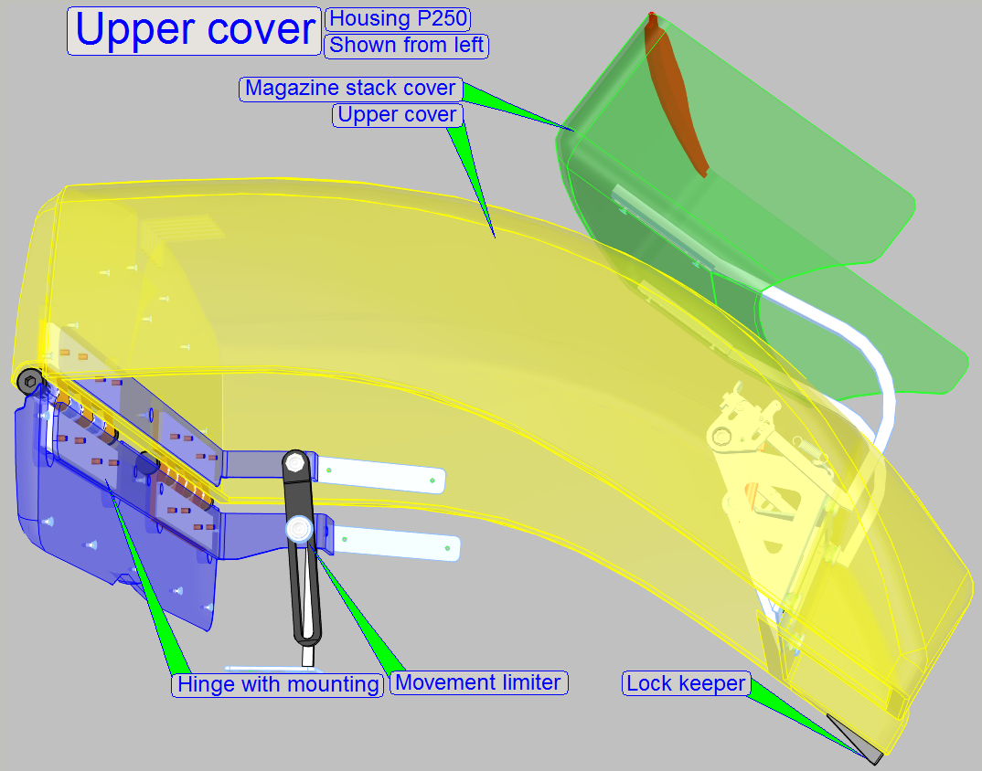
 The rear part of the upper cover is mounted to the
lower cover by using 2 hinges. Inside the hinges torsion springs are situated.
The rear part of the upper cover is mounted to the
lower cover by using 2 hinges. Inside the hinges torsion springs are situated.
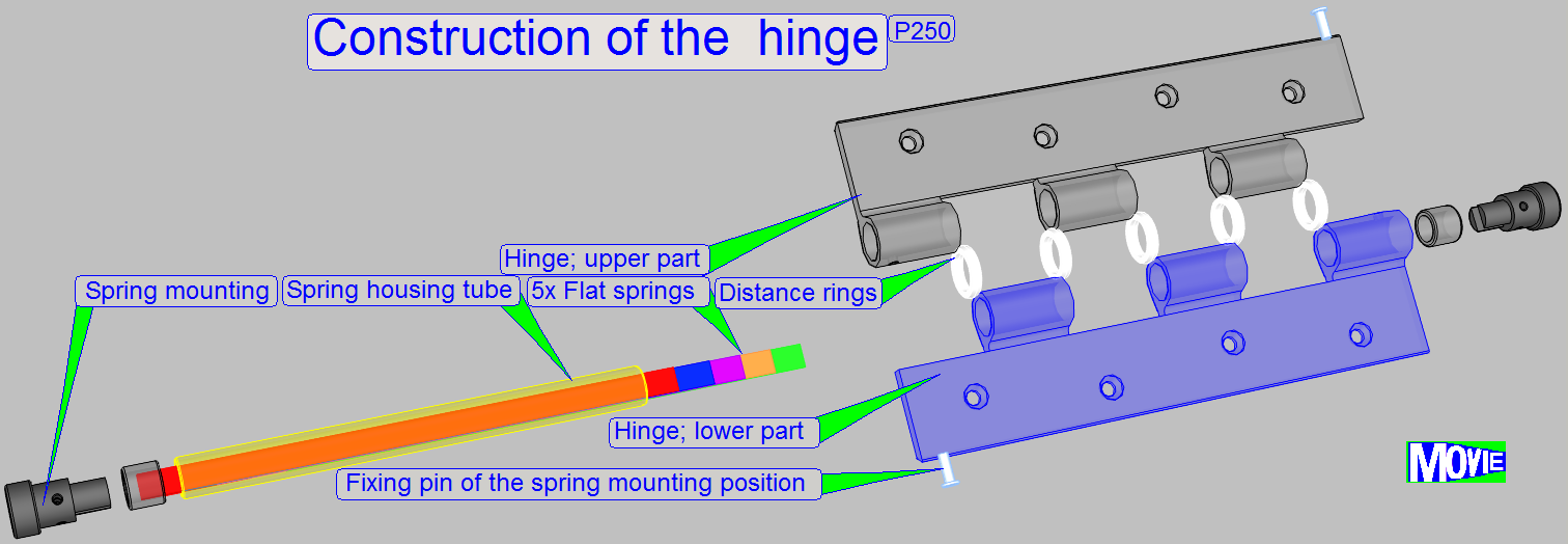
Hinge
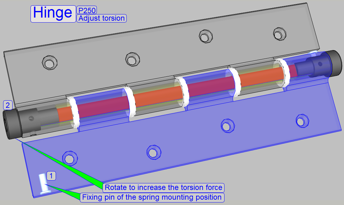 As mentioned, the hinge is equipped with a torsion
spring. After the fixing pin (1) of the spring mounting is removed, the spring
mounting (2) may be rotated by a hex key wrench. With this adjustment the
weight of the upper housing can be balanced by the torsion force of the spring.
The torsion can be defined in a fourth revolution of the spring mounting.
As mentioned, the hinge is equipped with a torsion
spring. After the fixing pin (1) of the spring mounting is removed, the spring
mounting (2) may be rotated by a hex key wrench. With this adjustment the
weight of the upper housing can be balanced by the torsion force of the spring.
The torsion can be defined in a fourth revolution of the spring mounting.
- The torsion
force of the springs in the left and right sided hinge together make the
upper cover to stay open.
Movement limiter
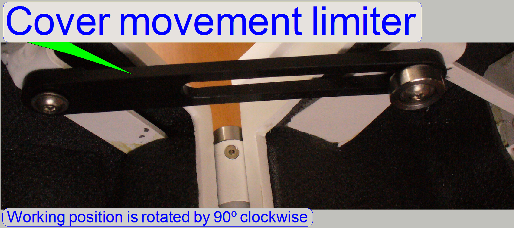 The torsion force of these springs, together with the upper
cover movement limiter makes the upper cover to stay open in its end position.
The torsion force of these springs, together with the upper
cover movement limiter makes the upper cover to stay open in its end position.
 The upper stack cover can be opened easily and quickly
to insert magazines into the magazine input stack or to remove magazines from the
output stack; it can not be separated from the upper cover.
The upper stack cover can be opened easily and quickly
to insert magazines into the magazine input stack or to remove magazines from the
output stack; it can not be separated from the upper cover.
- Lift up the
upper stack cover and move it upward in direction to the rear of the
scanner until it stops; in the end position, the stack cover should not
stay open.
- To close the
cover, easily release it, the cover closes itself by gravity.
- This cover
stays open only if you are holding it in its end position.
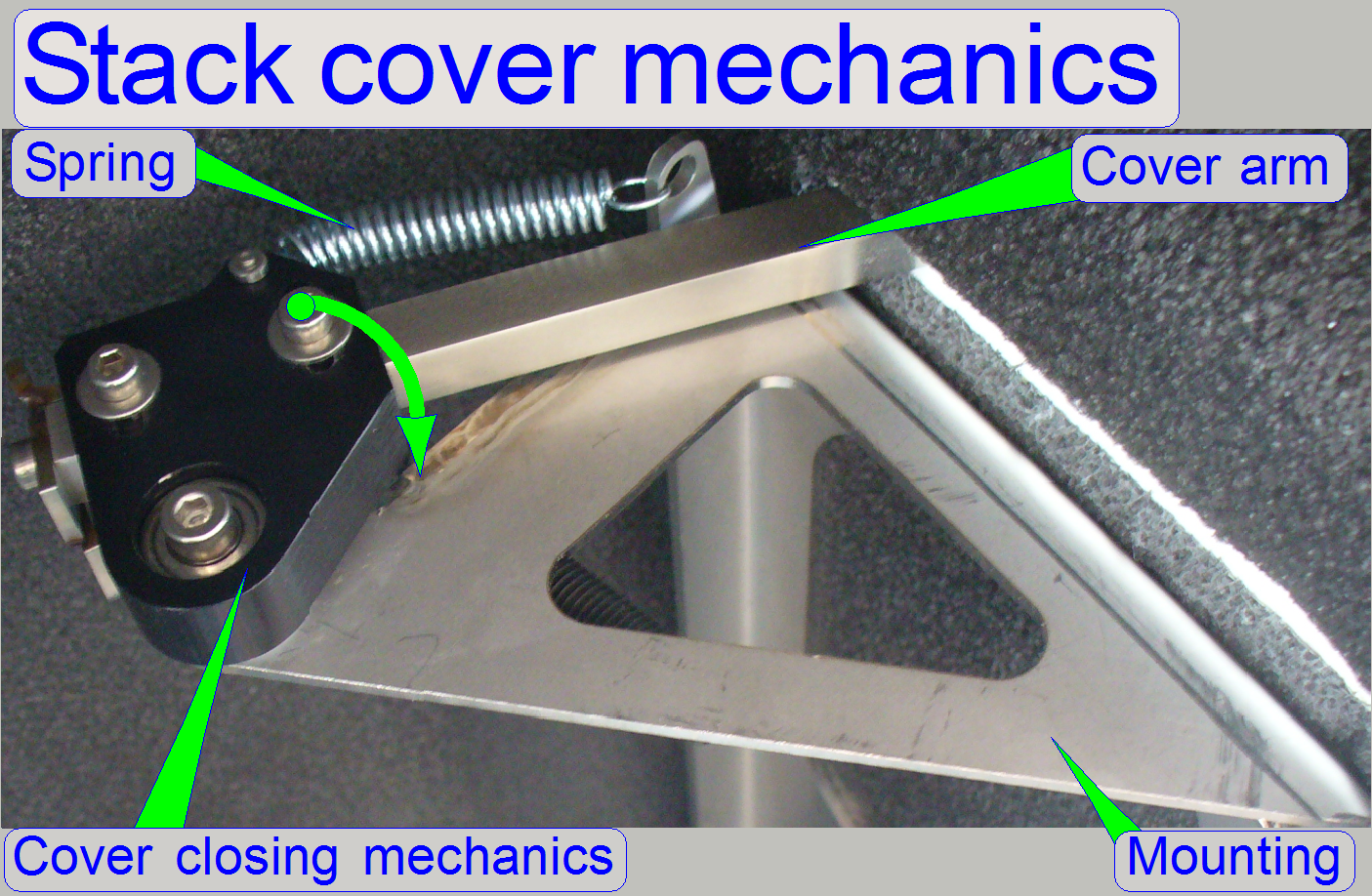 The stack cover mechanics is so constructed, that the cover
will close itself by gravity. To reach a smooth and slowly close operation on
both cover arms, springs are situated.
The stack cover mechanics is so constructed, that the cover
will close itself by gravity. To reach a smooth and slowly close operation on
both cover arms, springs are situated.
The springs create a force against the weight of the stack cover if the
stack cover will be closed and, if the stack cover is open, the springs
override the dead point by creating a little force to move the stack cover
downward until the gravity will acting.
- To fulfill
the requirements, the stack cover closing mechanics is adjusted.
 The emergency power off switch is situated in the
right handed side wall of the scanner and is used to inhibit the power supply;
the power distribution is interrupted and all movements are stopped
immediately.
The emergency power off switch is situated in the
right handed side wall of the scanner and is used to inhibit the power supply;
the power distribution is interrupted and all movements are stopped
immediately.
- If the power
is supplied again to the scanner, the software must be started again!
The rear cover of the housing is divided into three parts, the “Right
corner cover”, the ‘Rear wall” and the “Left corner cover”.
Rear wall
Mounting
· 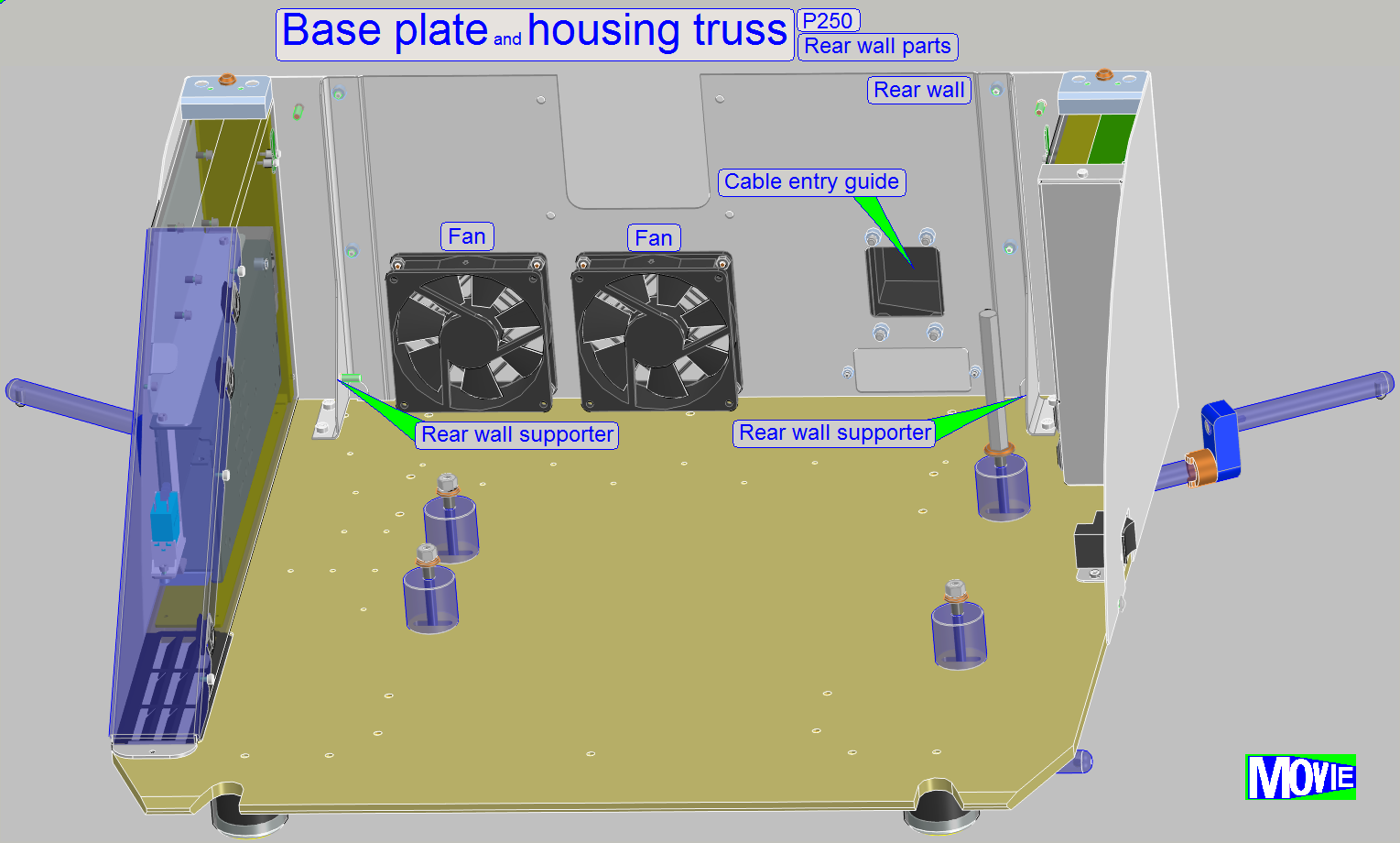 In the positions, where the
corner covers are mounted to the rear wall, two supporters are increasing the
mechanical stability of the rear wall.
In the positions, where the
corner covers are mounted to the rear wall, two supporters are increasing the
mechanical stability of the rear wall.
·  From outside, the rear wall is mounted to the base
plate with the bolts 1 and the corner covers are fixed to the rear wall by the
bolts 2 and 3 of the corner
covers.
From outside, the rear wall is mounted to the base
plate with the bolts 1 and the corner covers are fixed to the rear wall by the
bolts 2 and 3 of the corner
covers.
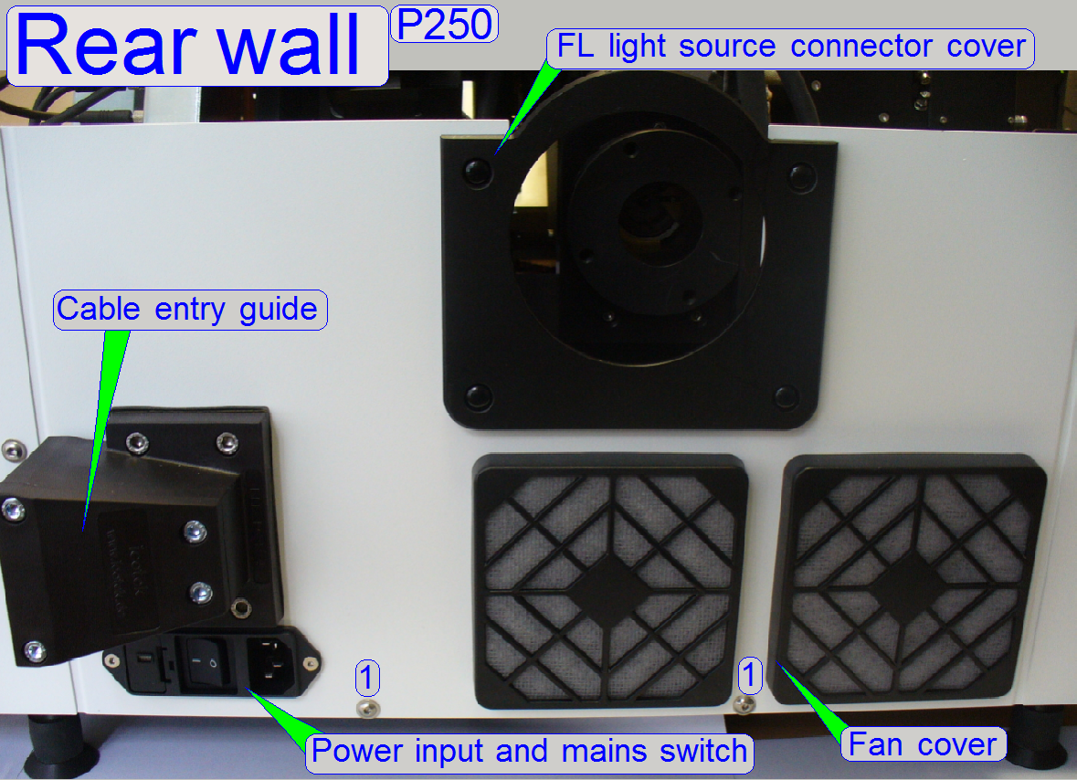
Power
input and mains switch
Cable
entry guide
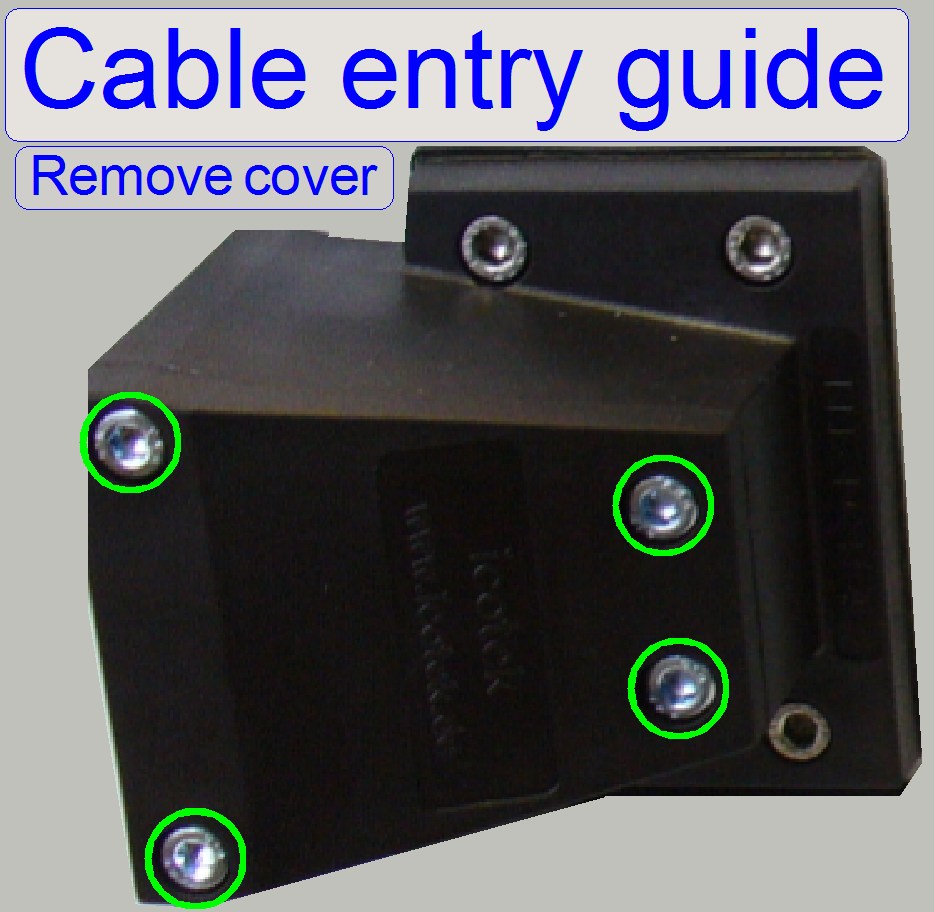 The cable entry guide covers the cable entry of the cameras
and other cables into the scanner.
The cable entry guide covers the cable entry of the cameras
and other cables into the scanner.
The cables are fixed by rubber inserts.
The following cables are guided (full
version)
· 2x camera link
cables of the camera “CIS”
· 2x camera link
cables of the camera “PCO.edge”
· 1x trigger cable of the
lumencor SPECTRA
· 1x power cable of
the lumencor SPECTRA
· 1x USB cable of
the preview camera
![]() Cable entry guide Type: KEL-FG B1; Page 14
Cable entry guide Type: KEL-FG B1; Page 14
Rubber inserts
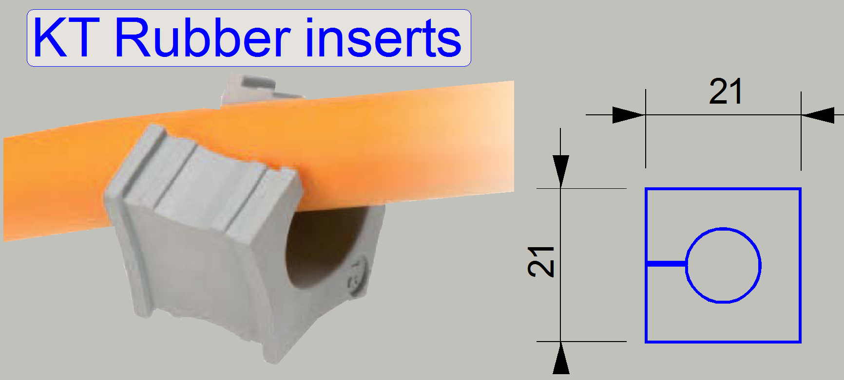 Because the configuration P250 BF and P250FL is
different regarding the amount of cables, different types of rubber inserts in
the cable entry guide are used.
Because the configuration P250 BF and P250FL is
different regarding the amount of cables, different types of rubber inserts in
the cable entry guide are used.
![]() Cable entry guide Type: KEL-FG B1; Page 20
Cable entry guide Type: KEL-FG B1; Page 20
![]() Differences between P250BF and P250FL
Differences between P250BF and P250FL
 The fan cover contains the particle and the dust
filter.
The fan cover contains the particle and the dust
filter.
The particle filter and the dust filter should be cleaned monthly, if
the room has an office character (carpeted floor).
If the scanner works in labor surroundings, the cleaning of the filter
inserts should be done four times at year.
· To reach the
filter inserts, please pull the fan cover (dust filter cover) easily backward.
How
to cleaning the filters
· If the fan cover
is removed, the filters can be separated easily.
· With canned air,
the dust can be blown off from the filters; first blow the air from the scanner
side of the filter, the cleaner surface.
· Fine dust can be
removed by using hand warm water mixed with a little bit non-aggressive
dishwashing liquid or hand washing lotion; wash the filter inserts, then rinse
these.
· The filters can be
blown dry by the use of any (heated) air blower (e.g. hairdryer or fan).
· Return the filter
inserts into the fan cover and mount it.
Mounting
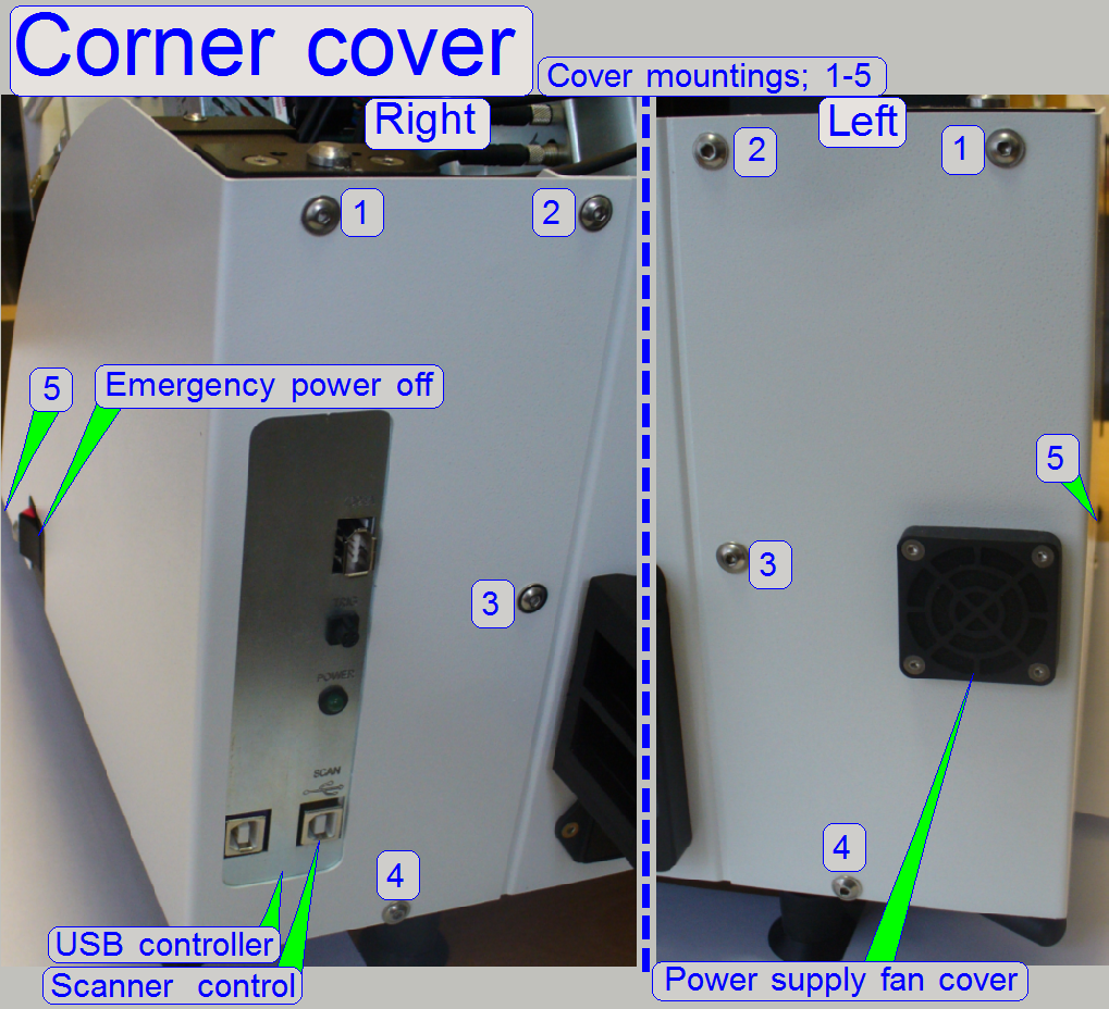 The right corner cover is mounted to the base plate
with the bolts 4 and 5 and is fixed to the housing truss with the bolt 1; the
bolts 2 and 3 are fixing it to the rear wall.
The right corner cover is mounted to the base plate
with the bolts 4 and 5 and is fixed to the housing truss with the bolt 1; the
bolts 2 and 3 are fixing it to the rear wall.
The left corner cover is mounted to the base plate with the bolts 4 and
5 and is fixed to the housing truss with the bolt 1; the bolts 2 and 3 are
fixing it to the rear wall.
- By removing
the bolts 1, 2 and 3 and loosening the bolts 4 and 5 the appropriate
corner cover can be removed upward.
- To reach the
USB controller unit, the right corner cover has to be removed; see also: USB controller
mounting.
Power
supply fan cover
If the 4 mounting bolts are removed, the dust filter can be reached
easily.
· To clean the
filter insert, please see above “Fan covers 1, 2”
Construction; P250
The scanner Pannoramic 250 consists if the following main components
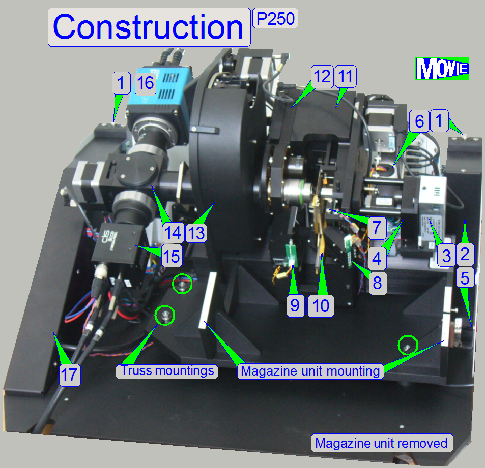
1.
Cover mounting
on the rear
3.
Pulsed xenon flash
light source for brightfield
scan mode
4.
Neutral density (ND)
filter unit with collimator lens
holder
5.
Emergency
power off switch
6.
X-Y-Z-ND-motor
and flash controller electronics
7.
Brightfield
preview illumination
8.
Darkfield
preview illumination
10. Specimen holder
11. Focus unit
13. Turret unit
15. CIS camera for
brightfield scan mode
16. PCO edge camera; used if fluorescent
scan mode is selected.
17. Power supply and distribution
electronics housing
18. Magazine unit (not shown here)
· For
safety regulations regarding human health and scanner functionality please
refer to: Precautions
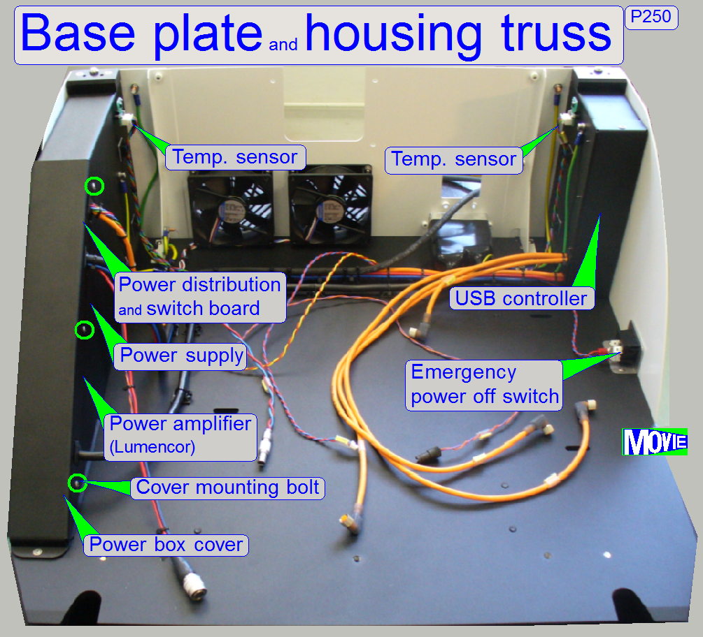
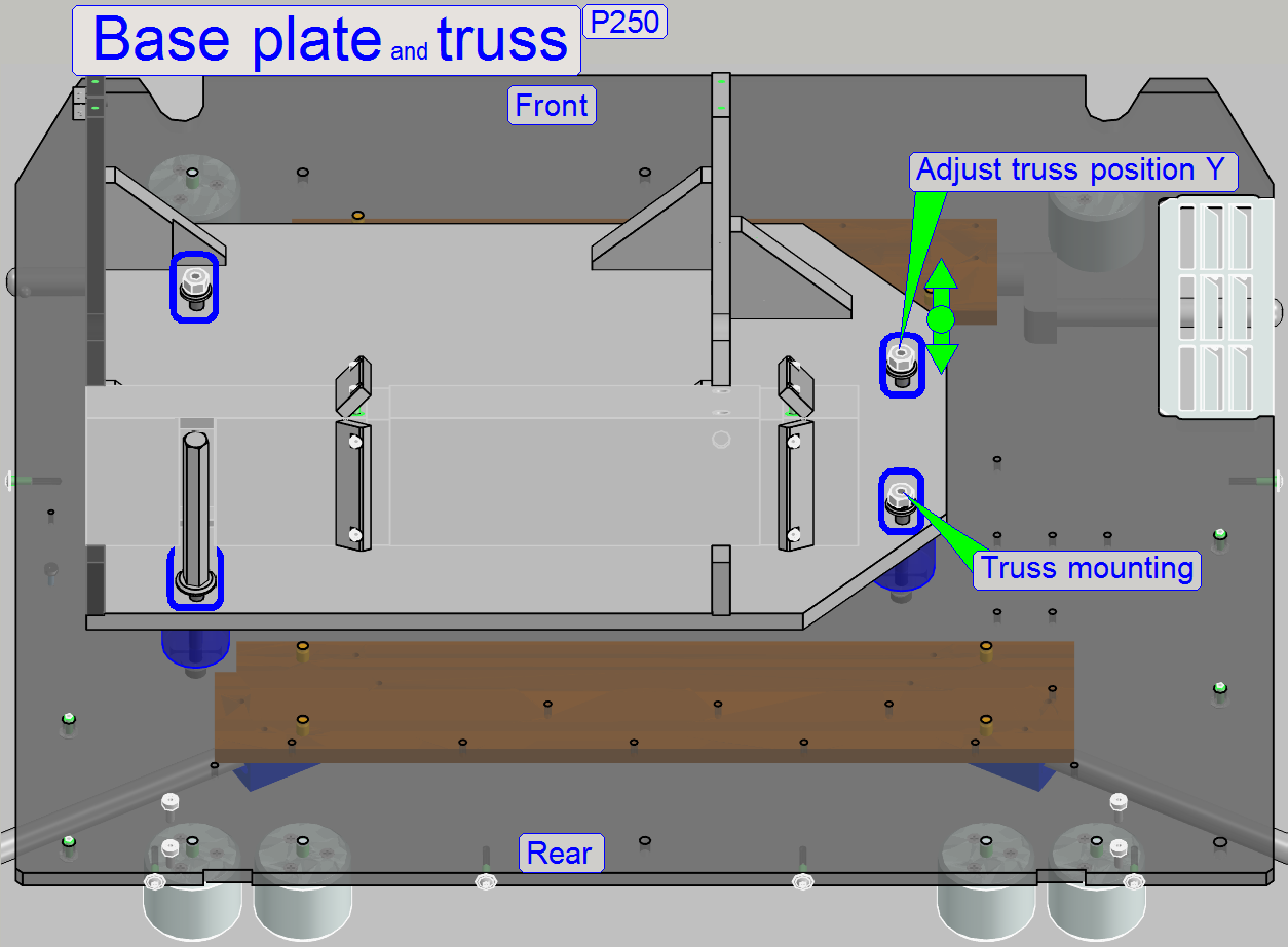
The base plate and
housing truss consists of the following main components:
· Base plate with rubber feet and handles; mounted
from beneath.
· Long holes to
mount and positioning
the scanner truss.
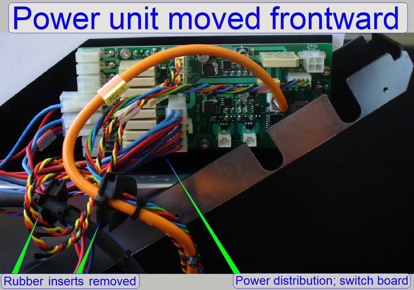
· Power box,
containing the power unit (power supply, distribution and
switch board and the power
amplifier).
· USB controller box
![]() “Adjust the truss
position”; “Mounting
of the current amplifier”; “Mounting of the
power unit”; “USB
controller”
“Adjust the truss
position”; “Mounting
of the current amplifier”; “Mounting of the
power unit”; “USB
controller”
· Loosen the upper
and lower power box cover mounting bolts and remove the mounting bolt in the
middle.
· Pull the power box
cover upward
 To move the P250, 4 handles are mounted near the
corners of the base plate from beneath.
To move the P250, 4 handles are mounted near the
corners of the base plate from beneath.
Pull the handles to the left (on the left side) and to the right (on the
right side) and rotate them upward. By using the handles, the scanner can be
moved safely by two persons.
1.
Pull the handle to the left or to the right
respectively until it stops, then
2.
Rotate the handle upward.
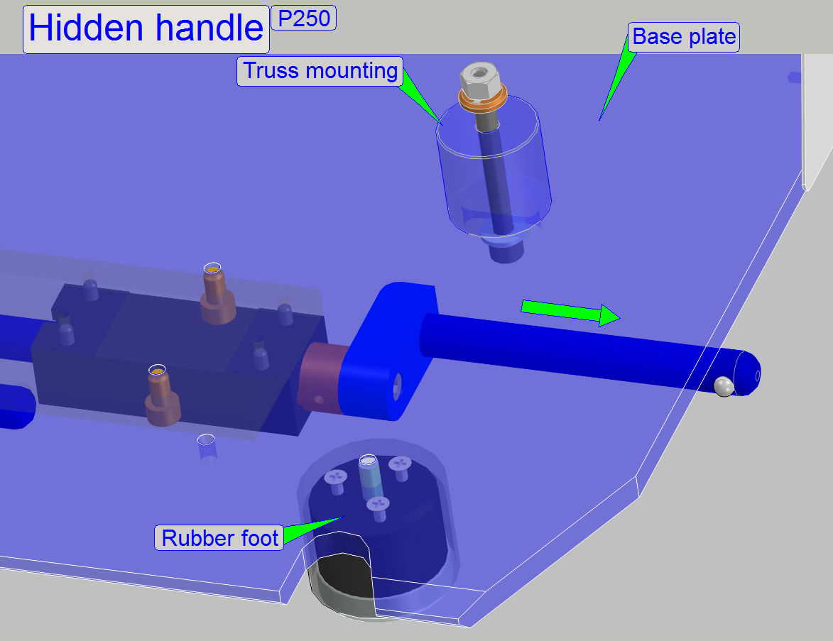
Hide handles
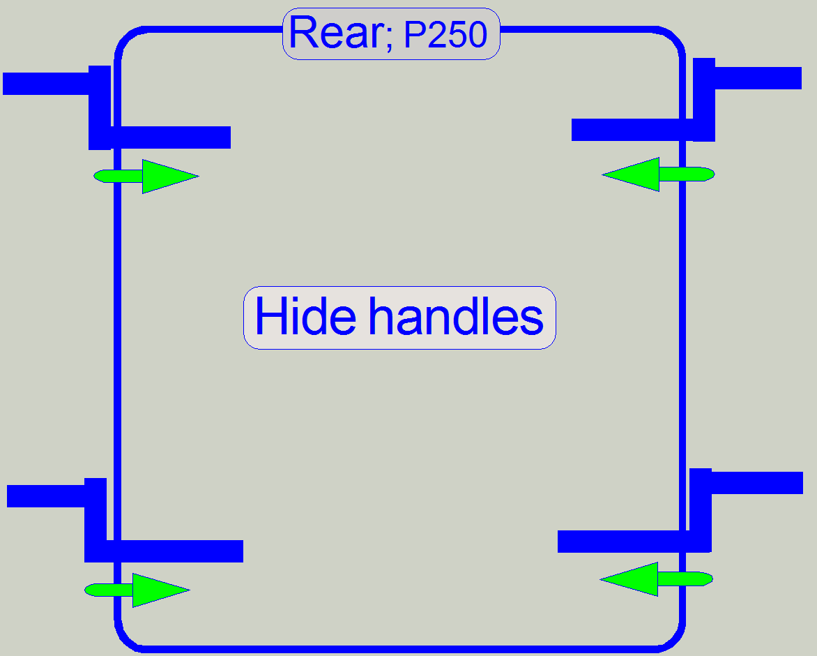 After the destination is reached, the handles can be
hided again.
After the destination is reached, the handles can be
hided again.
1.
Rotate the handle to the rear of the scanner as shown,
then
2.
Push the handle in direction to the center until it
stops.
· In the hidden
position, the handle will be fixed against rotating downward from itself.
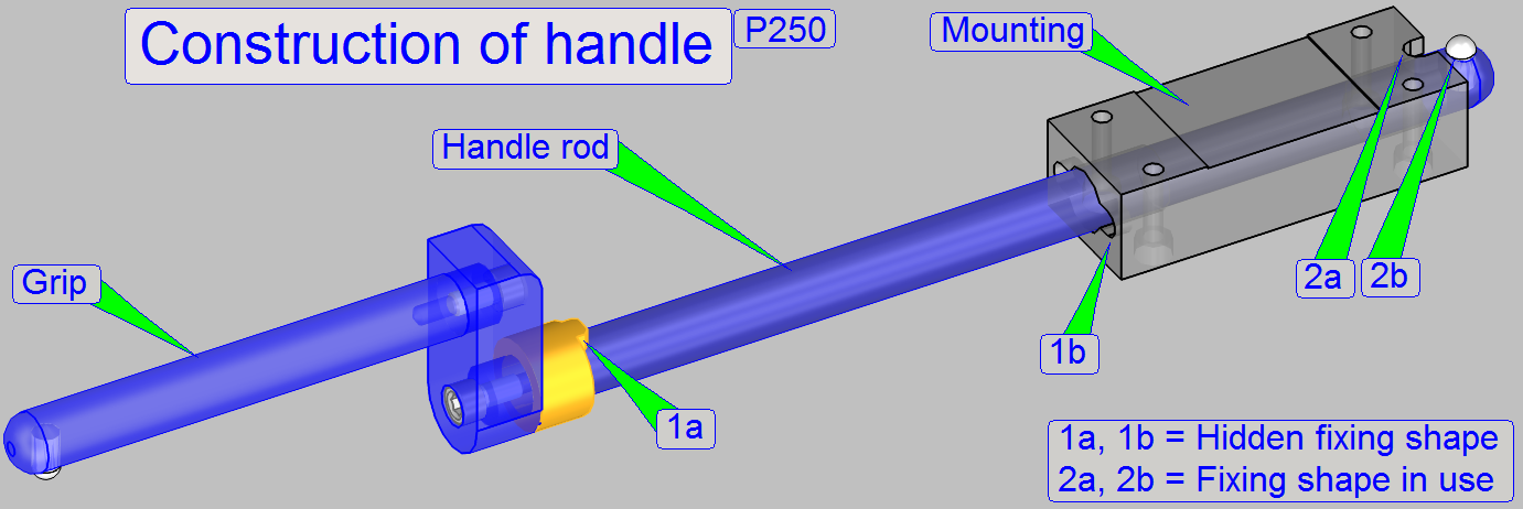 The handles are used to move the P250.
Each handle has two defined positions, the hidden position and the
position "in use" (as shown); in both positions a fixing is realized.
The fixing, shown as shapes 2a and 2b are used during moving the scan,
so the handle will not rotate, it stays always upward.
If the handle is pushed into its hidden position, the shapes 1a and 1b
fitting each other and the handle can not rotate downward by gravity.
- Before rotating
the handle sideward during hiding the handle, push the handle a bit to
release the fixing (2).
- If the hidden
position is reached, the fitting of the shapes (1) can be reached by
pushing and jarring the handle grip a bit upward and downward.
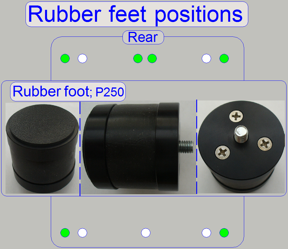 The P250 is placed on the table by the use of 6 rubber
feet; their positions on the base plate are shown on the right.
The P250 is placed on the table by the use of 6 rubber
feet; their positions on the base plate are shown on the right.
The number of the rubber feet and their arrangement reduce vibration and
resonance.
· Drive in the
rubber foot in the threaded drilling at the specified position until it stops.
Mounting of the power unit (power supply)
The entire power unit (power supply, power distribution and switch board
and the power amplifier of the lumencor SPECTRA) is mounted onto the power
supply “TDK-Lambda”.
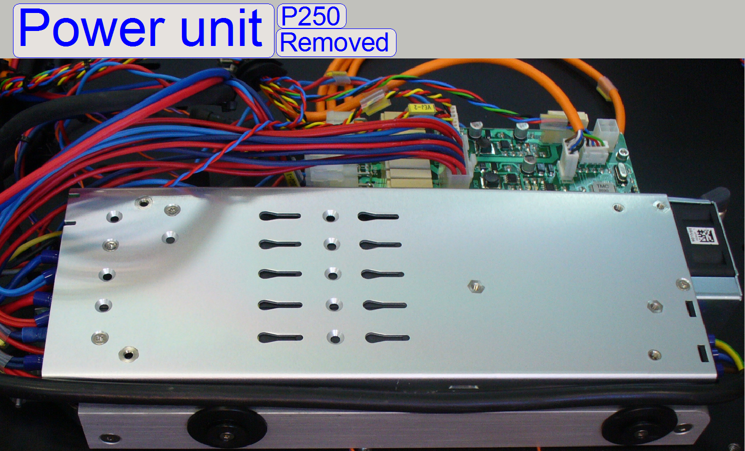
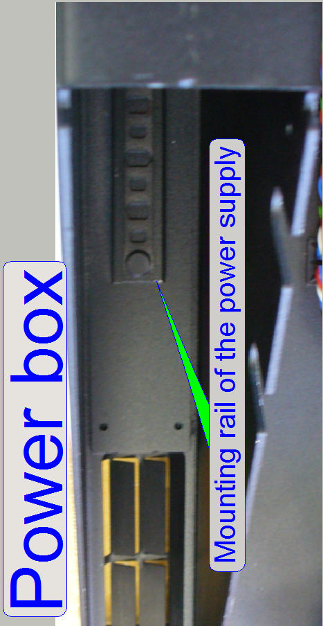 On the lower edge of the power supply mounting discs
are situated from beneath, so the power supply can be shifted in the mounting
rail, situated on the bottom of the power box.
On the lower edge of the power supply mounting discs
are situated from beneath, so the power supply can be shifted in the mounting
rail, situated on the bottom of the power box.
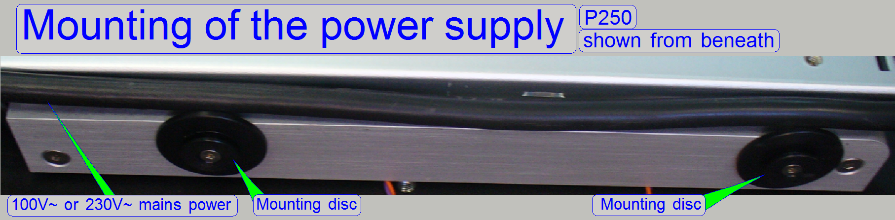
Please shift the entire power unit only frontward or
backward.
· If
the power unit will be inclined sideward or upward during the removal or insert
procedure, the mounting discs will be destroyed!
Remove
the Power supply
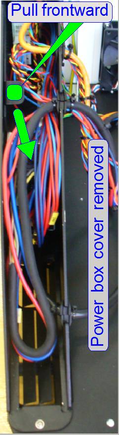
- Disconnect
the power cable or switch off the scanner on the main switch.
- Remove the
power box cover.
- Remove the
rubber inserts.
- Pull the
entire power unit straightly frontward as desired; see also “Important”
above.
- May be the power
box cover bolt in the middle must be removed.
Mounting of the current
amplifier
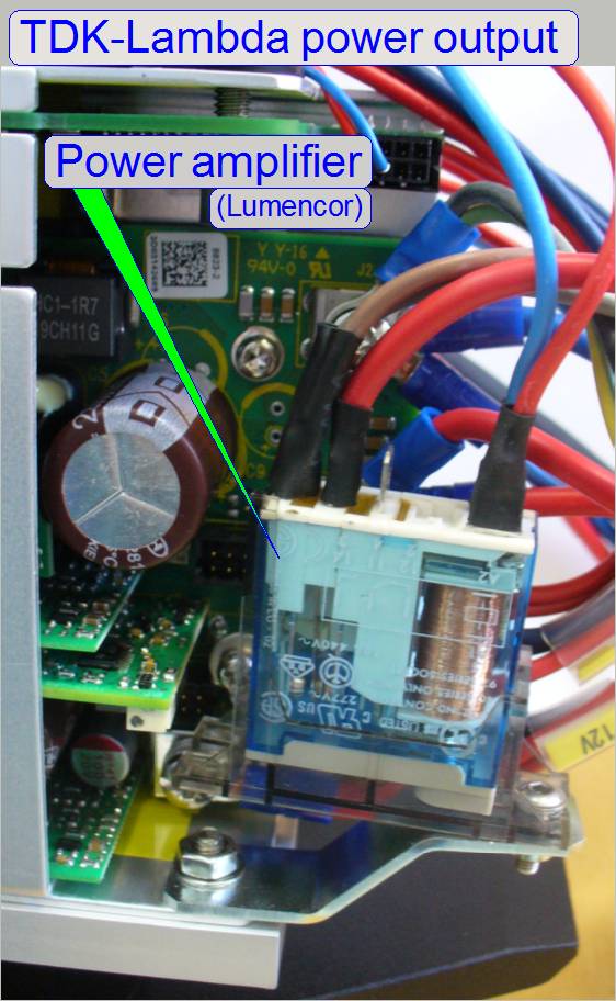
The relay, to switch the power for the lumencor SPECTRA light engine is
situated near to the power output of the power supply “TDK-Lambda”.
![]() “Current amplifier” and
“Lumencor SPECTRA light
engine”
“Current amplifier” and
“Lumencor SPECTRA light
engine”
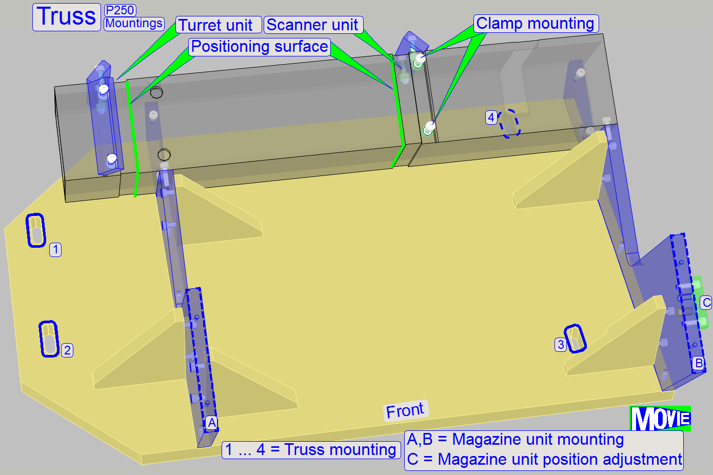 Main components of the truss are
· Magazine
unit mounting and position adjustment
The truss holds the entire scanner mechanics; the microscope part and
the scanner part as well, because the distance of the units to each other is
very important.
The positioning surfaces of the truss, together with the locating
surfaces of the scanner plate and the locating surface of the turret plate
define the distance of the units to each other and guarantee the straightness
of the optical axis also.
The magazine unit mounting defines the position of the magazine unit in
relation to the X-X-stage unit and scanner plate.
The long holes in the truss base plate are used to positioning the truss
in relation to the housing.
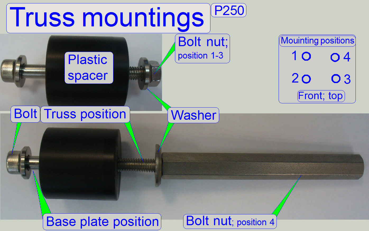 Each mounting of the truss consists of a bolt with
washer and a bolt nut with washer. The plastic spacer is situated between the
base plate and the truss.
Each mounting of the truss consists of a bolt with
washer and a bolt nut with washer. The plastic spacer is situated between the
base plate and the truss.
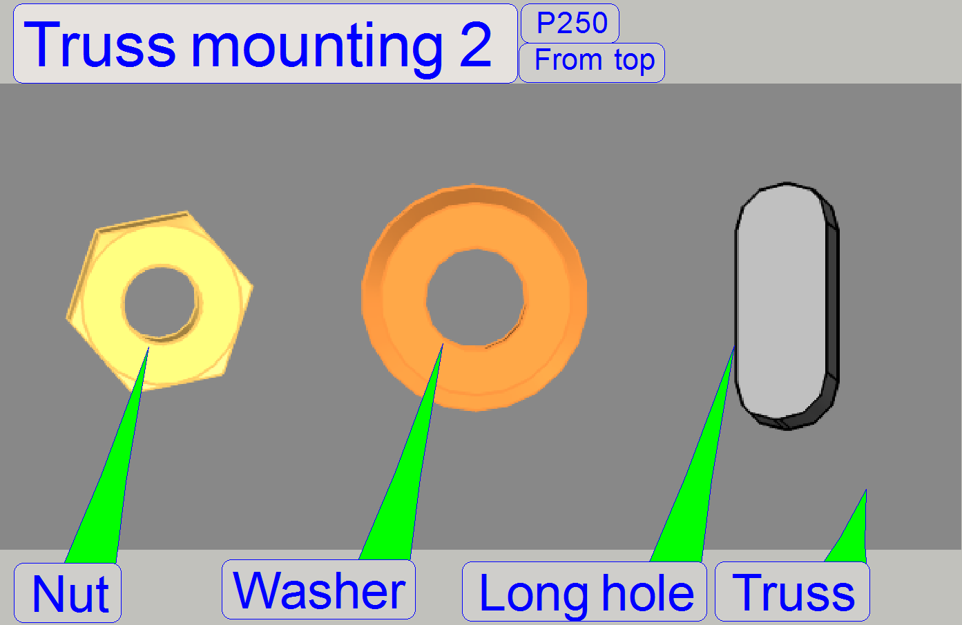
By loosening the mounting nuts, the long holes in the base plate
allowing the position adjustment of the entire truss in the mathematical
X-direction (left / right).
 The truss is mounted to the bolts by using a washer
and a bolt nut. With a long hole solution in the truss mounting plate, the
position of the truss (the entire scanner) can be adjusted in relation to the
housing; no parts of the scanner must touching the housing if all covers are
mounted.
The truss is mounted to the bolts by using a washer
and a bolt nut. With a long hole solution in the truss mounting plate, the
position of the truss (the entire scanner) can be adjusted in relation to the
housing; no parts of the scanner must touching the housing if all covers are
mounted.
By loosening the mounting nuts of the truss with a 10th
wrench, the long holes in the truss allow the position adjustment of the entire
scanner in the mathematical Y-direction (frontward / backward).
The long holes in the truss allow the positioning of the truss in the
direction frontward and rearward (the mathematical Y-direction)
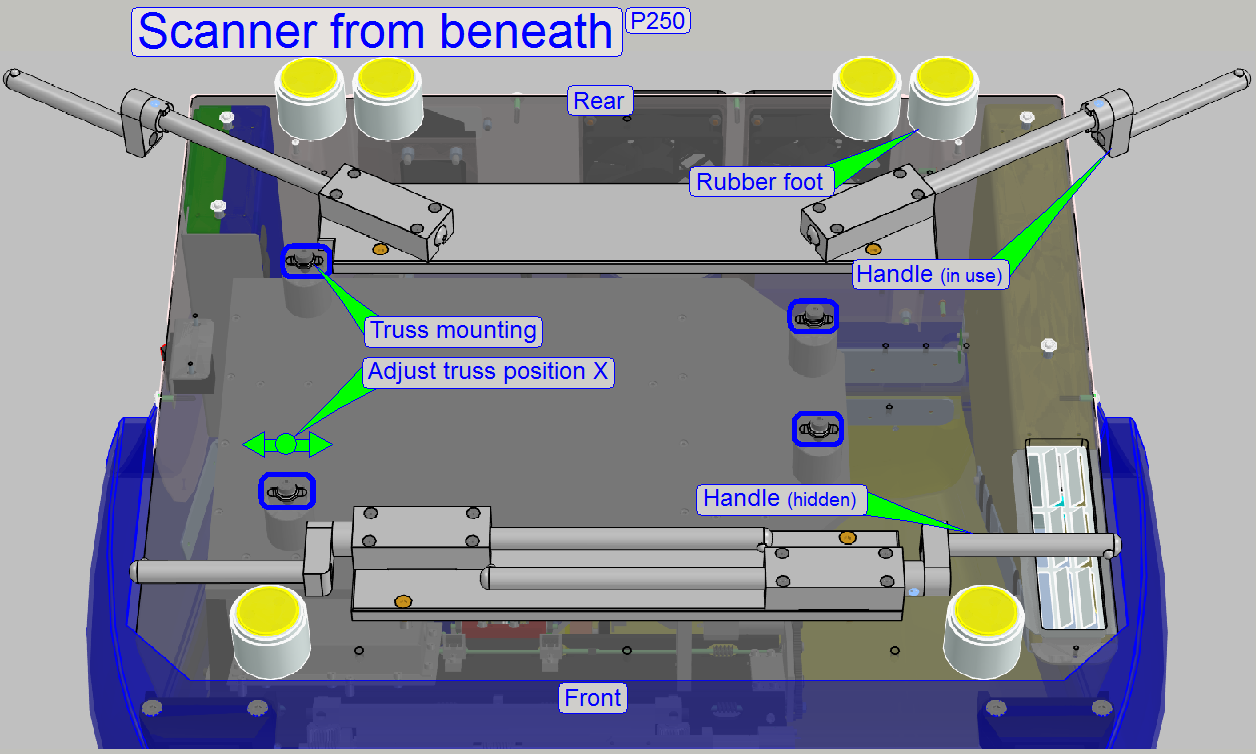
The long holes in the base plate allow the positioning of the truss in
the direction left and right (the mathematical X-direction).
 To ensure, that the entire scanner does not touch the
housing, and to positioning the stack cover, the position of the scanner truss
should be adjusted.
To ensure, that the entire scanner does not touch the
housing, and to positioning the stack cover, the position of the scanner truss
should be adjusted.
The spacers are mounted from beneath with 6mm hex key bolts and the
truss is mounted to the bolts by using a washer and a bolt nut; see also above
“Truss mounting””.
·
Adjust the position of the truss so, that no internal
part touches the housing and the input and output stacks are working correctly.
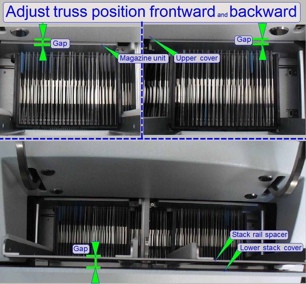
Adjust the truss
position in the direction frontward / backward (the mathematical Y-direction)
- Loosen the
truss mounting nuts with a 10th key wrench and pull the entire
truss frontward until the magazine channel side wall (the input and output
stacks) are not covered by the upper cover of the housing.
- The size of
the horizontal gap is not important; it can be about 1 or 2mm; see also
the gaps in the upper part of the figure on the right.
- There should
be also a gap between stack rail spacer and the lower stack cover; see the
lower part of the figure on the right.
- Tighten the
truss mounting nuts.
Adjust
the position of the truss in the direction left and right (the mathematical
X-direction).
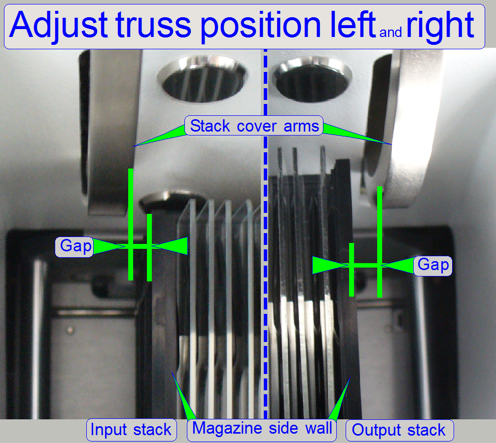 Insert 5 magazines into the input stack and insert the
other 5 magazines into the output stack.
Insert 5 magazines into the input stack and insert the
other 5 magazines into the output stack.
If the stack cover will be closed, the stack cover arms should not hit
the magazine side wall; there should be a gap to the magazine side wall on the
input stack side and on the output stack side as well.
Move the truss to the left or to the right respectively, until the
requirements are fulfilled; the size of the gaps should be nearly equal on both
sides, this has only an esthetic aspect.
- Loosen the
truss mounting bolts on the base plate side from beneath.
- Define the
position of the truss left and right, until the requirements are
fulfilled.
- Tighten the
mounting bolts.
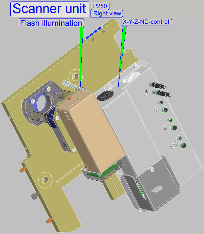 The scanner unit consists of:
Scanner plate with
the mounting to the truss
Focus unit with
objective changer
Brightfield scan illumination (ND-filter unit with xenon flash light
source)
Mounting standoffs for the X, Y, Z, ND controller
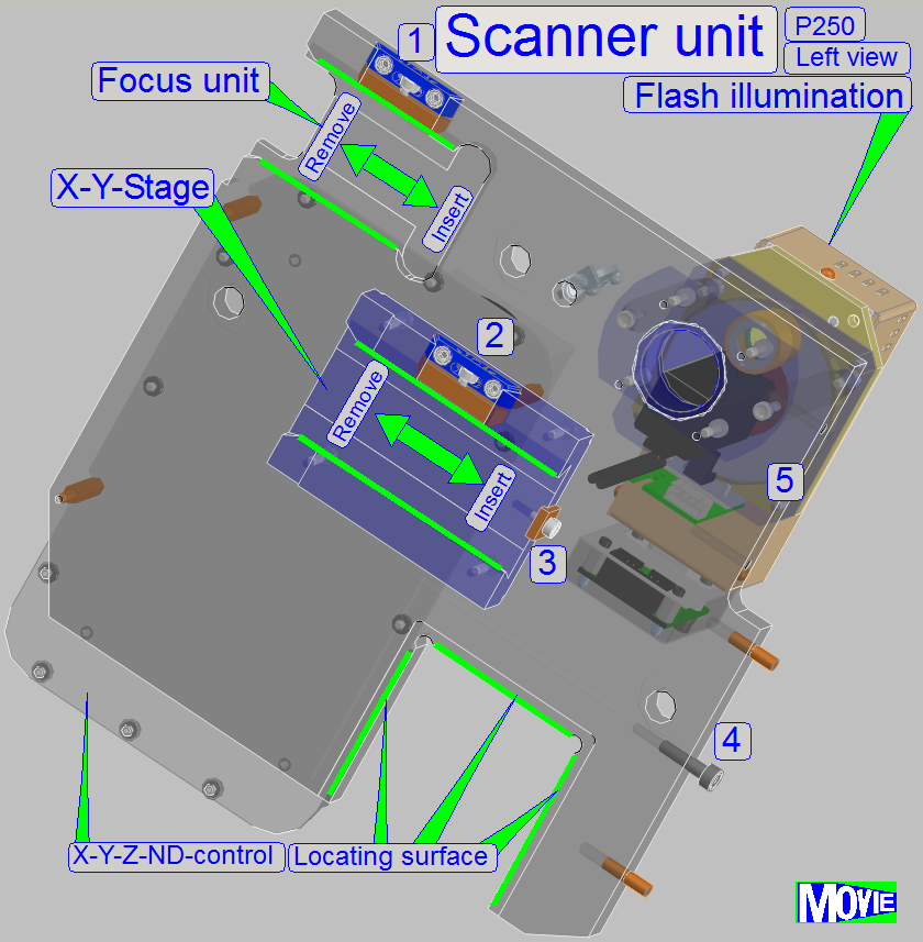
· Focus unit’s dovetail
mounting
· Focus unit’s dovetail
fixing (1)
· X-Y-stage unit’s
dovetail mounting
· X-Y-stage unit’s dovetail
fixing (2)
· Preview unit’s
horseshoe mounting (4)
· Preview
illumination unit’s mounting (5)
· Brightfield scan
illumination mounting (ND-filter unit)
· X-Y-stage unit
bumper with mounting (3)
· Mountings
for the X-Y-Z-ND
control
To define the distance of the scanner unit in relation
to the turret unit and to ensure the straightness of the optical axis, locating
surfaces are used.
![]() “Turret
and scanner unit mounting” and “Tightening
sequence”
“Turret
and scanner unit mounting” and “Tightening
sequence”
Focus and X-Y-stage unit’s dovetail mounting
Focus and X-Y-stage unit’s dovetail fixing
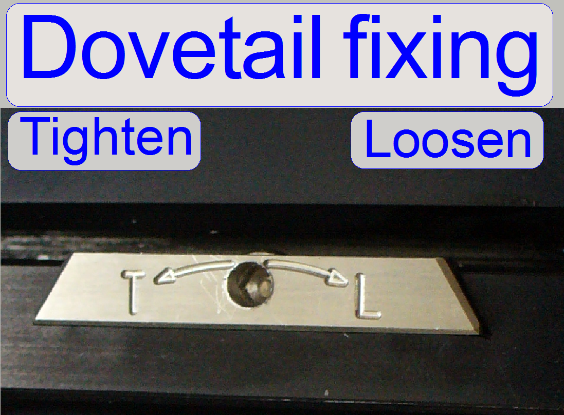 The mounting of the focus unit with objective changer
and the mounting of the X-Y-stage unit are realized with dovetails; these are
hold by dovetail fixing clamps.
The mounting of the focus unit with objective changer
and the mounting of the X-Y-stage unit are realized with dovetails; these are
hold by dovetail fixing clamps.
- Rotate the 2.5 hex key wrench
clockwise to open (loosen) the dovetail clamp.
Preview unit’s horseshoe mounting
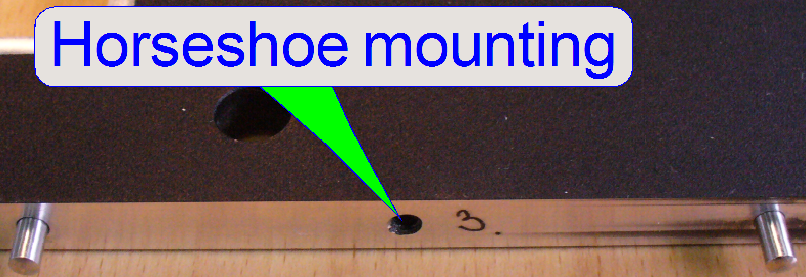 The horseshoe mounting contains two fixing
pins to define the position and a threaded hole for the mounting bolt.
The horseshoe mounting contains two fixing
pins to define the position and a threaded hole for the mounting bolt.
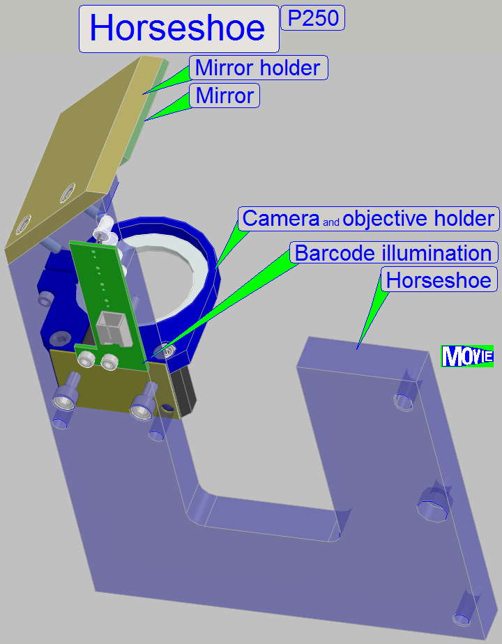
The horseshoe is
the mounting part of the preview unit, and contains the mountings of following
components:
- Objective
and camera holder
- Preview mirror mounting
- Barcode
illumination
The entire preview unit is situated on the edge of the
scanner plate, parallel to the magazine unit.
The position is fixed with two fixing pins and hold by
the mounting bolt.
Remove the
preview unit
· Remove
the mounting bolt and then the entire preview unit can be removed frontward.
Mount the preview
unit
· Fit
the fixing pins of the scanner unit into the position fixing holes of the
horseshoe and push the entire preview unit onto the edge of the scanner unit.
· Drive
in the mounting bolt.
Preview objective
and camera holder
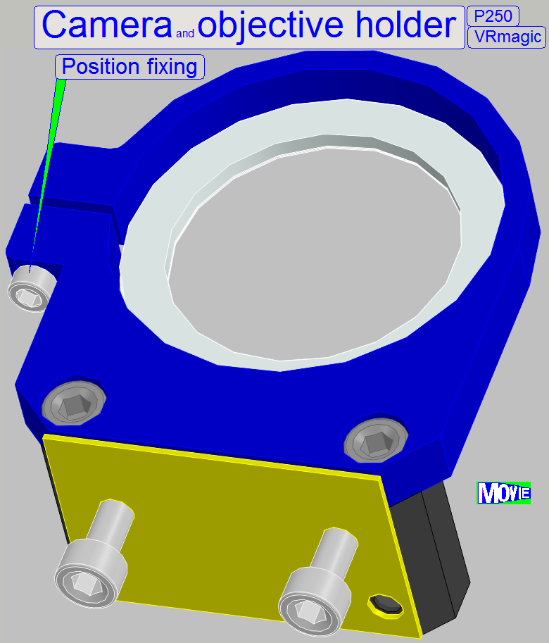 The
preview objective and camera holder allows the adjustment of the preview camera
rotation angle in a limited range.
The
preview objective and camera holder allows the adjustment of the preview camera
rotation angle in a limited range.
To adjust the camera rotation angle:
- Hold the camera from beneath (the rear of the camera) and loosen
the position fixing bolt a little bit until the camera becomes barely
rotate-able.
- By loosening one of the “Rotation angle” bolts and tightening the
opposite bolt, the rotation angle will be modified.
- If the correct camera rotation angle is found, tighten the
“Position fixing” bolt; further information can be found in the chapter “Adjust the
preview camera rotation angle”.
 Preview illumination unit’s mounting
The preview illumination unit consists of a
brightfield unit and a darkfield unit.
The entire unit is mounted with 2 bolts onto the edge
of the scanner plate, beside the horseshoe.
![]() “The preview illumination unit”
“The preview illumination unit”
Brightfield scan illumination mounting (ND-filter
unit)
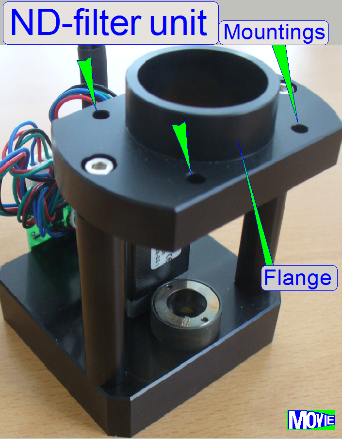
The flange of the
ND-filter unit is mounted with 4 bolts to the scanner plate.
![]() “Neutral density (ND) filter unit”
“Neutral density (ND) filter unit”
X-Y-stage unit mounting with bumper
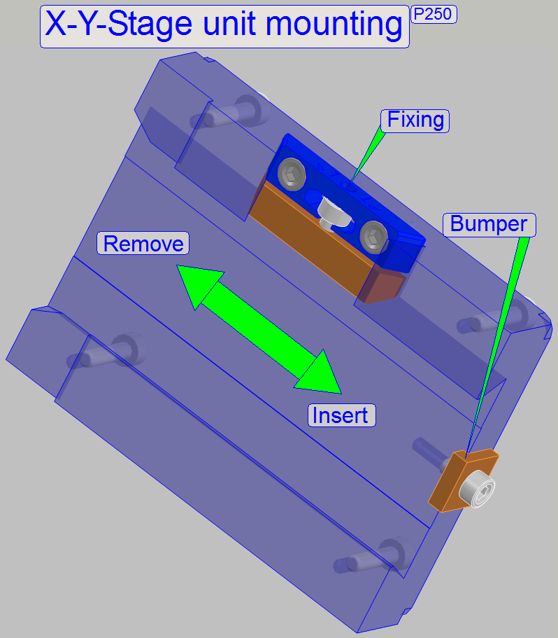
The distance of the X-Y-stage unit in relation to the
magazine unit is defined by the size of the X-Y-stage unit bumper.
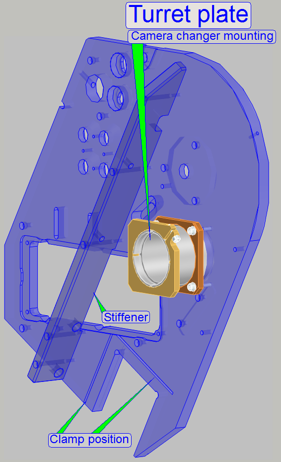 The turret plate is used if the P250 is delivered in the
version BF only and contains the mounting for:
The turret plate is used if the P250 is delivered in the
version BF only and contains the mounting for:
Camera
changer unit
In the drillings of the camera changer the clamp will hold the camera
changer mounting.
Supporter
position
In this position the supporter bolt with supporter tube is mounted.
Stiffener
(P250 and SCAN)
Because the turret plate is in vertical position in the P250 (and in the
SCAN also) a stiffener increases the mechanical stability.
![]() “Differences between P250BF and P250FL”;
“Turret plate”
“Differences between P250BF and P250FL”;
“Turret plate”
Attention
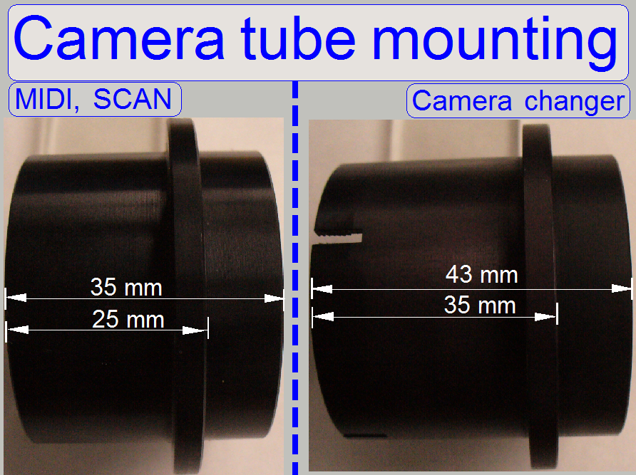 The camera changer mounting of the P250 differs in
length from the camera tube mounting in the SCAN 150 and the
The camera changer mounting of the P250 differs in
length from the camera tube mounting in the SCAN 150 and the
Turret and scanner unit mounting
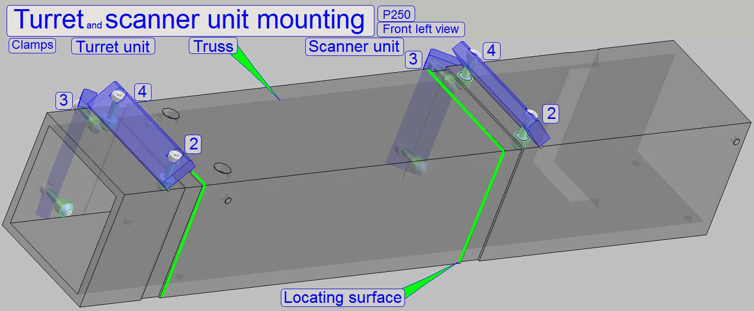 Because the distance between turret unit and scanner unit
is important, the mounting is realized by using a locating surface on the unit
and so, the unit is fixed to the truss by using clamps.
Because the distance between turret unit and scanner unit
is important, the mounting is realized by using a locating surface on the unit
and so, the unit is fixed to the truss by using clamps.
· The
construction of the clamps for the turret unit and for the scanner unit is
identical.
· The
correct mounting of the scanner unit and the turret unit is important for the
straightness of the optical axis.
Only by tightening the clamp bolts in the right
sequence, the locating surface fits correctly.
The scanner plate
is tightened logically in the same sequence.
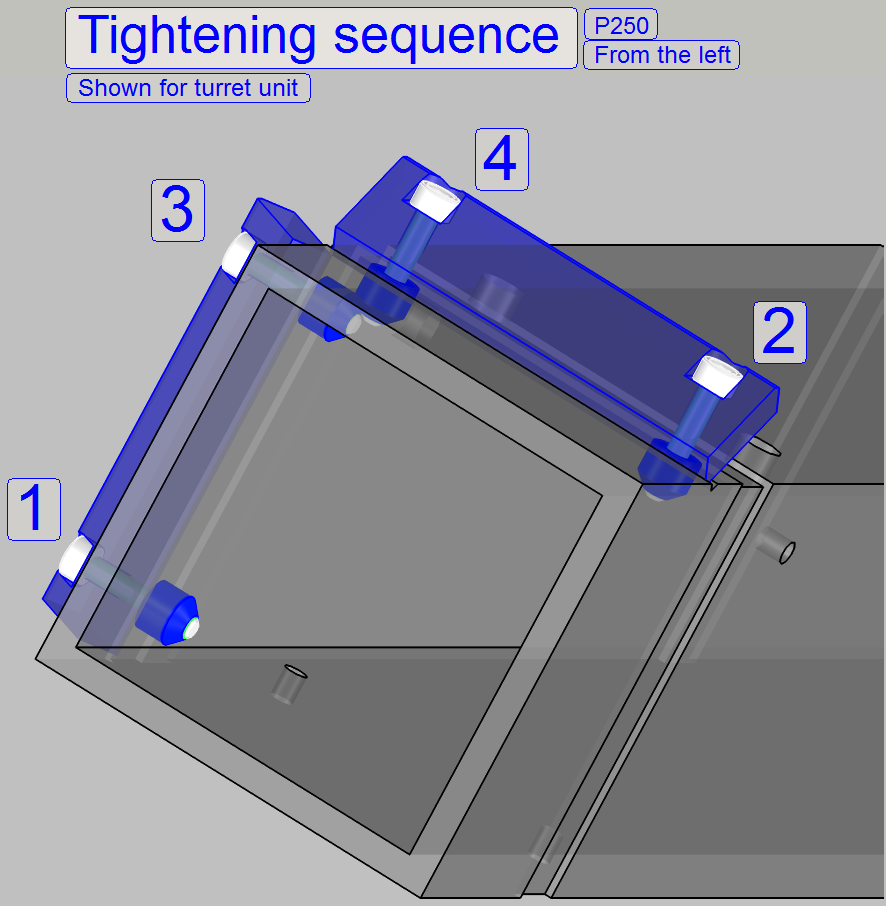
1
Lower rear bolt
2
Top bolt frontward
3
Upper rear bolt
4
Top rear bolt
During tightening the clamp bolt (1) move the turret
unit (turret plate) or the scanner plate on its upper part carefully sideward
(toward and away from the scanner unit or the turret unit respectively) until
no movements can be expired or the bolt is tightened. Then tighten the clamp
bolt (2). Only this way, the locating surface will fit correctly. The sequence
of the bolts (3) and (4) is less important because these bolts are near to each
other.
To remove the turret plate or scanner plate, loosen
the bolts 1 and 3 and remove the clamp, fixed with the bolts 2 and 4; then the
plate can be pulled upward and frontward in an angle of 30 degrees.
![]() Remove or mount the FL reflector turret unit
Remove or mount the FL reflector turret unit
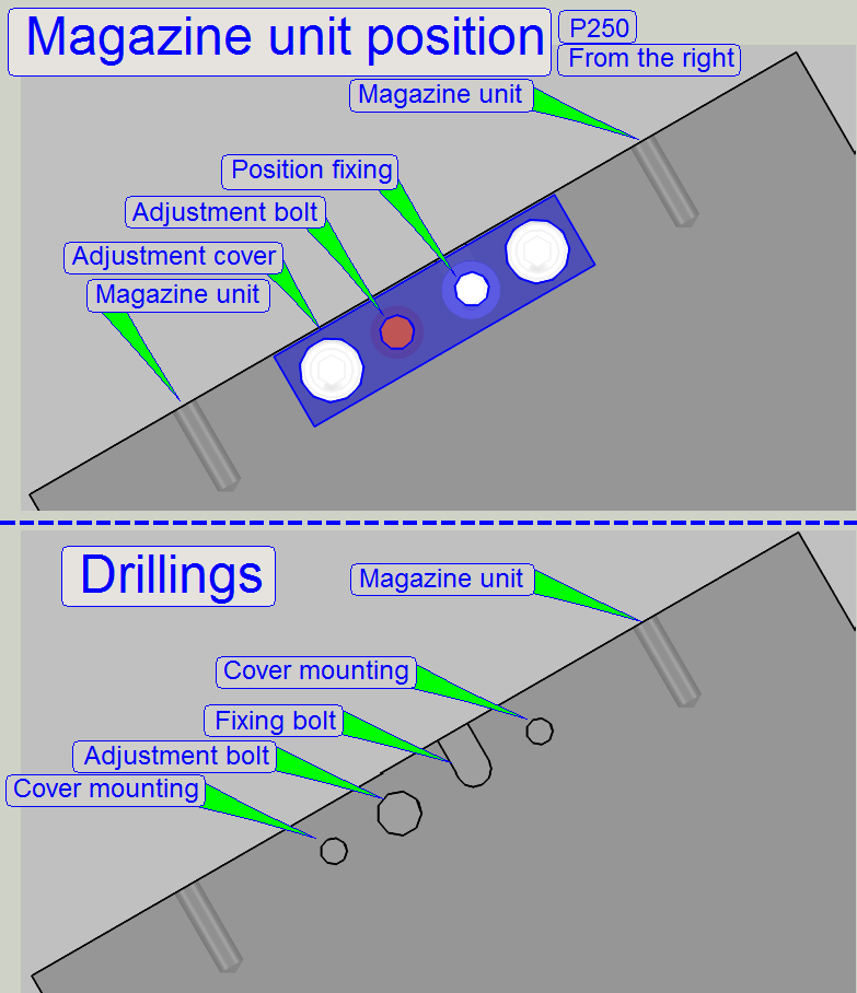 On the right
side of the magazine unit mounting, the magazine unit position adjustment and
fixing is realized.
On the right
side of the magazine unit mounting, the magazine unit position adjustment and
fixing is realized.
With this solution, many adjustments may be left out, if the magazine
unit was removed and mounted again.
Adjust
magazine unit position
The goal of the adjustment is the fitting of the slide loader position
in relation to the specimen holder position; so a smooth slide insert and slide
removal action can be reached.
- To adjust the
magazine unit position, loosen the magazine unit mounting bolts first.
By loosening the fixing bolt and driving the adjustment bolt inward or
by driving the adjustment bolt outward and tightening the position
fixing bolt, the position of the entire magazine unit can be shifted on the
mathematical X-direction (left/right).
- If the
desired position is reached, tighten the magazine unit mounting
![]() Adjust
the magazine unit position
Adjust
the magazine unit position