Housing, construction
For technicians and partly for sales managers!
 This chapter handles the
construction and components of the housing as well as the construction of the
entire Immunohistochemistry Staining automatic Cover slipping and Scanning
equipment (iSaCS). Mainly mountings of the units and components, relation of
the units to each other and the construction of mechanical units are discussed.
This chapter handles the
construction and components of the housing as well as the construction of the
entire Immunohistochemistry Staining automatic Cover slipping and Scanning
equipment (iSaCS). Mainly mountings of the units and components, relation of
the units to each other and the construction of mechanical units are discussed.
·
Description is based on the software version 1.20 and
the scanner’s part is based on “Pannoramic
·
For safety regulations regarding
human health and scanner functionality please refer to: Precautions
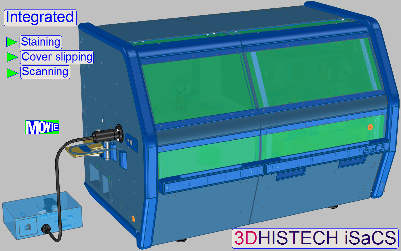
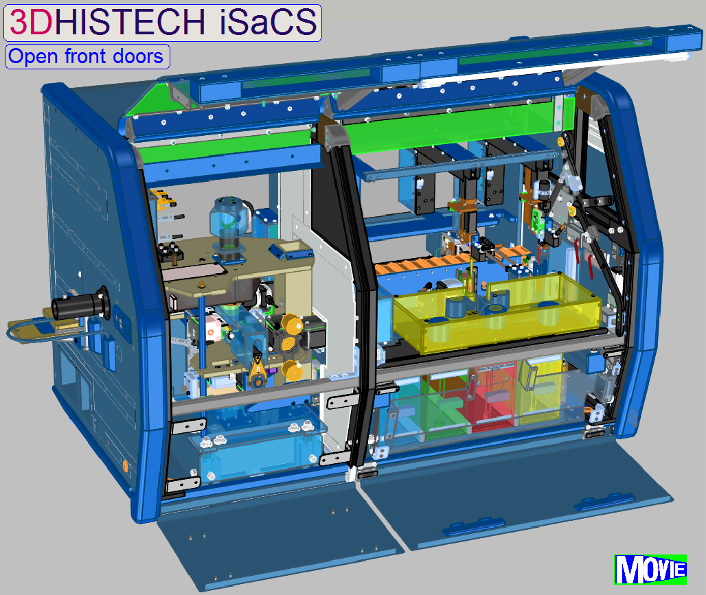
The housing
of the equipment consists of
- Base
frame with 4 rubber feet.
- Top cover; not removable.
- Rear wall; removable for service purposes.
- Right-side cover; designed as service door.
- Left-side cover; designed as service door.
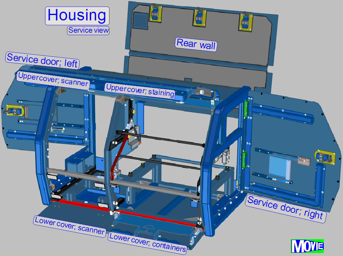
Four front covers
- Top right front cover to reach the staining
units.
- Top left front cover to reach the scanner.
- Bottom right cover to reach the wash and rinse
containers.
- Bottom left cover; always closed, no service parts behind.
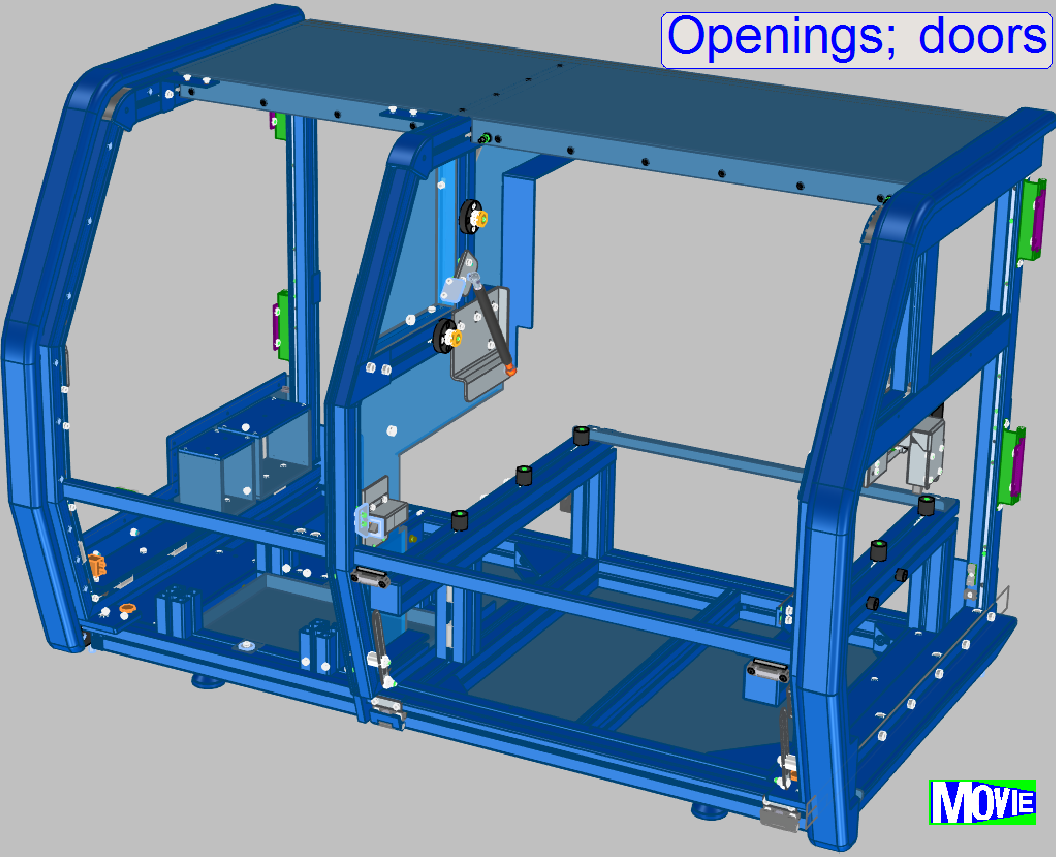
Bottom left front cover (see movie
"Openings; doors")
- Not removable for service purposes; always closed.
Bottom right front cover (see
movie "Openings; doors")
- Two cover handles
- Container supporter (inner side)
- Two safety labels
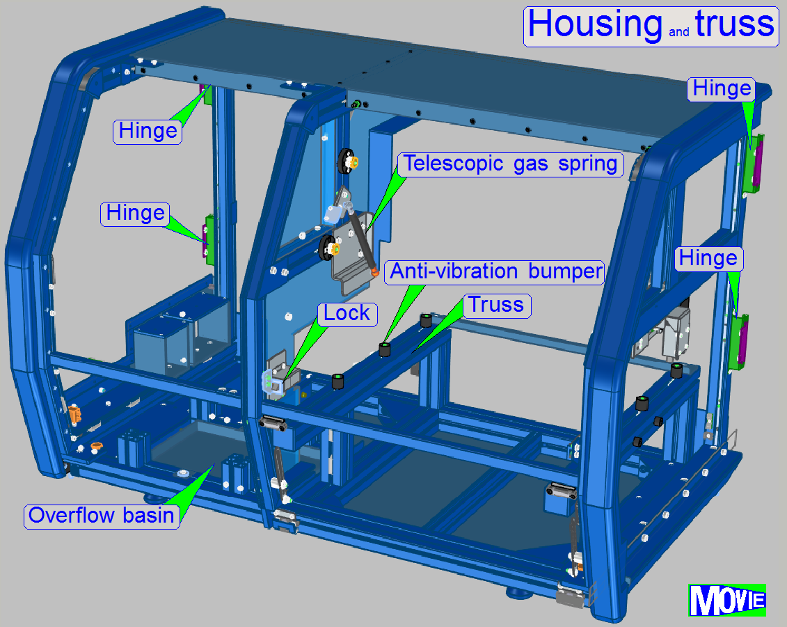 Top left front cover (see
movie "Openings; doors")
Top left front cover (see
movie "Openings; doors")
- Rod
linkage to support the open movement of the cover
- Cover
handle
- Cover
truss
- Telescopic
spring to keep open the cover
- Illuminated 3DHISTECH logo
Top
right front cover (see movie
"Openings; doors")
- Rod linkage to support the open movement of the
cover
- Cover opening switch
- Cover handle with product name
- Cover truss
- Telescopic spring to keep open the cover
Top cover (see
movie "Openings; doors")
- Increases stability for the entire housing truss
- Mounted permanently; not removable
Rear wall (see
movie "Openings; doors")
- Removable for service purposes
- Three door locks with Allen-key opening
- Upper and lower sponge for silencing purposes
(inner side)
- Cooling air exit
- Two cover fixing plate
Right-side
cover (see movie "Openings; doors")
- Functioning as service
door
- Door lock with Allen-key opening
 Slide rack window with
handle
Slide rack window with
handle- Micro switch (inner side)
Left-side cover (see
movie "Openings; doors")
- Functioning as service door
- Fluorescence frame for protection purposes
- Mounted fluorescence light opening
- Sliding door with handle (inner side)
- Door lock with Allen-key opening
- Safety label
- Tray insert opening
- Slide information label
- Bottom cover part
- Start-up switch with power LED
- Serial information label
- 4 USB ports
- Power input
- Label of electronics
- NAUSB-W port
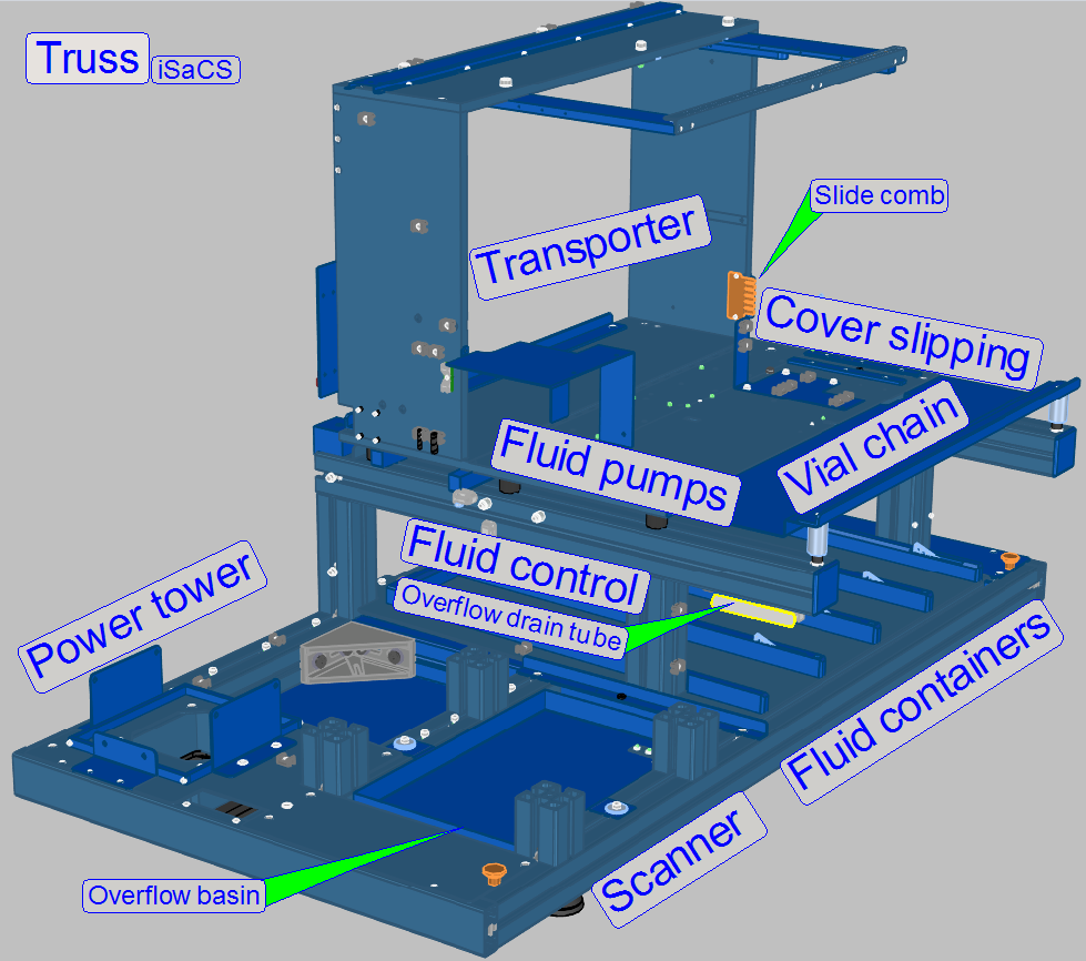
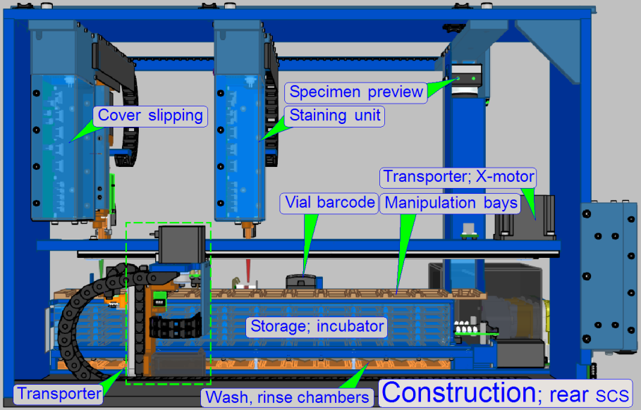
Construction; iSaCS
Behind the housing of the
iSaCS main units are easily distinguishably
· Truss
Mainly the construction and components of the units are shown, detailed information
will be found in the description of the unit itself.
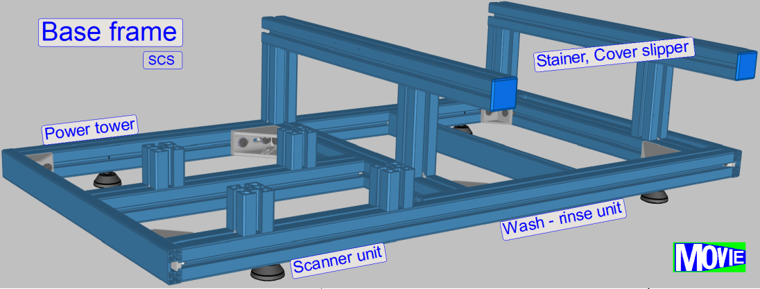
The base frame holds the entire equipment and the housing.
The truss defines the
mountings and the position of the units and components to each other.
Slide comb
If the slide rack will be inserted from the right side of the equipment,
the slide comb is used to check the correct position of the slides in the slide
rack.
· Slanted placed
slides in the slide rack or not fully inserted slides will prevent the
insertion of the rack!
Overflow basin
The overflow basin gathers fluid in emergency situations.
· To drain the
basin, remove the overflow drain tube from its holder and connect a syringe
with a capacity of 50ml and suck out the fluid.
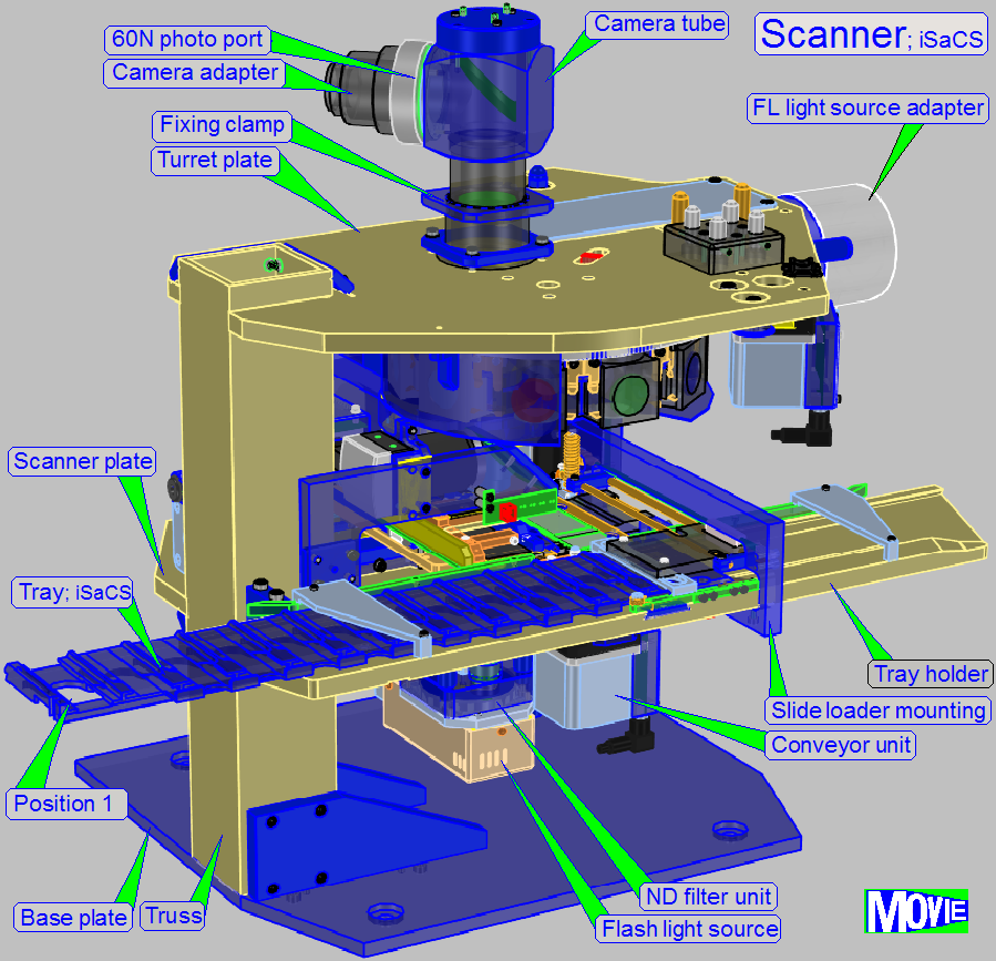
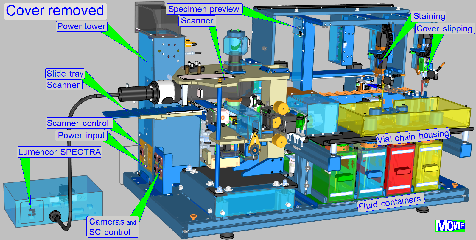
The scanner’s part of the
ISACS consists of the following main components:
1.
Mounting
(Base) plate with mountings to the ISACS truss
2.
Scanner
unit
3.
Image path with objective
changer and tube lens
4.
60N Photo port with Spinning
disk unit and scan camera PCO.edge
5.5Mp (not shown)
5.
Tilting table with immersion liquid feeder, objective
changer and entire image path
6.
Mounting for the FL illumination unit table; for Lumencor
SPECTRA light engine
7.
Power tower; with power supply and
main control electronics
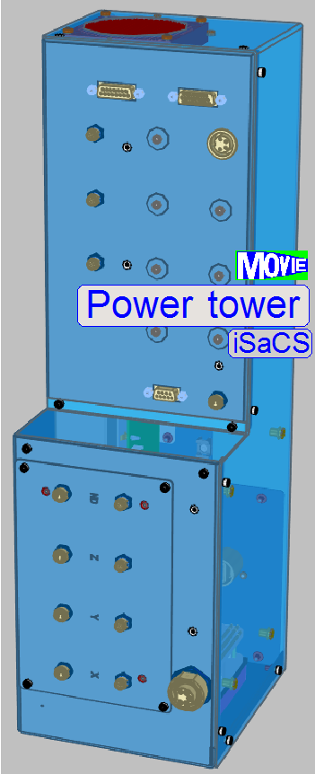
The power tower contains the
power supply and control electronics, mainly for the specimen scanner unit.
All other units, related to staining and cover slipping are controlled
via a separate, central and local electronics unit.
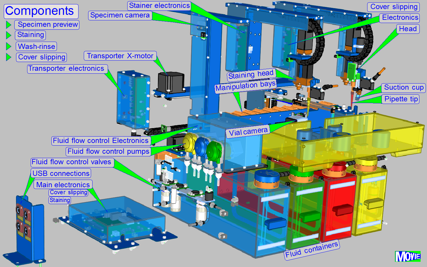
Main components are
·
Main control
·
Transporter control
·
Staining control
·
Vial chain control
·
Wash-rinse control
·
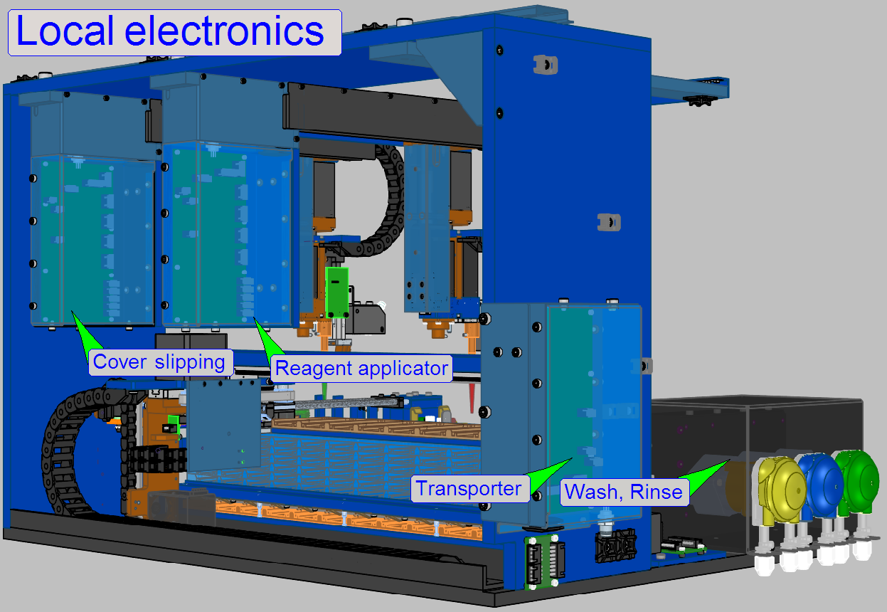 Cover slipping
control
Cover slipping
control
 The transporter unit is situated
behind the slide storage unit and moves the slide from the slide rack to any
required position in the storage, and returns into the slide rack.
The transporter unit is situated
behind the slide storage unit and moves the slide from the slide rack to any
required position in the storage, and returns into the slide rack.
The transporter is able to move the slide by the help of the slide mover
in X-Y-Z directions.
For more information about the transporter
![]() “Transporter”.
“Transporter”.
Slide storage
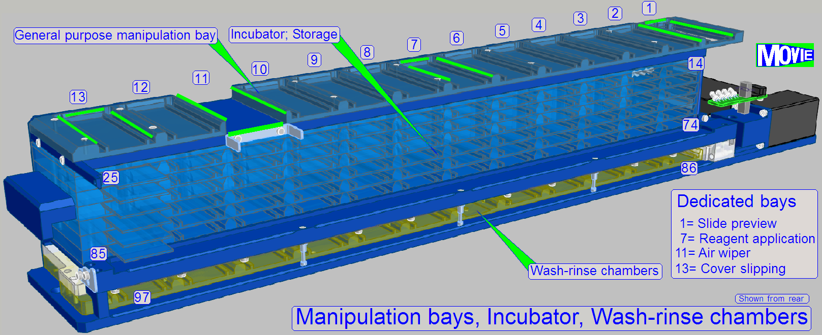 Slide storage can be divided
into following components
Slide storage can be divided
into following components
· Manipulation; 13
bays
· Slide rack,
Incubator; 72 slide bays
· Wash and rinse
chambers; 12 positions
As visible, 97 storage places are realized in the unit and these are
numbered as shown. Nevertheless, the maximal number of slides during a preparation
session is limited to be 72 slides, the capacity of the slide rack. All other
possible slide places are used during the creation process and have often
special tasks.
This arrangement allows the execution of different tasks simultaneously,
e.g. while one slide stays in the washing and rinsing process, the stain may be
applied to another specimen, a 3rd slide may be covered with the
cover slip during the capturing of the specimen preview may be done on a 4th
specimen and the transporter may move a slide into a required position during
scanning of a 5th slide.
This small example shows the modularity of the equipment and this
modularity helps to save execution and preparation time.
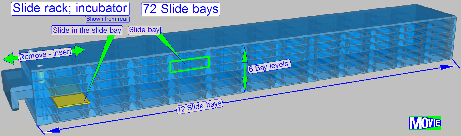
The slide rack (or
slide container or also named as incubator) is removed and inserted from the
right side of the equipment by the help of the handle.
· Insert the filled
slide rack and press it into the fixing position.
· The correct
inserted slide rack position is sensed via a micro switch.
The slides, containing the specimen and a barcode, can be inserted into
any slide bay, face up; a special sequence is not required. Slide bays may be
left blank, as desired!
· The slides with
specimen are inserted manually, face up into the slide container
· The container is
removed or inserted from the right side of the equipment
· Contains up to 72
slides for 1 creation process session.
· Important The slides are
not fixed in the bays
Slide
tray
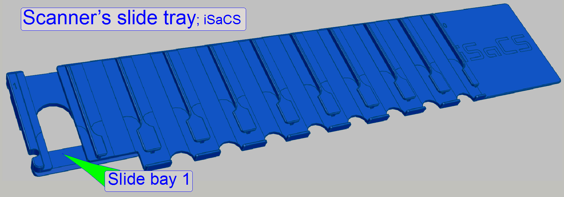
The slide transporter puts the slide into “Bay1” of the slide tray.
After this the scan process starts.
When the scanning of the slide is finished, the transporter removes the
slide from “Bay1”, and returns the slide to its original place in the slide
rack.
The action will be performed by moving the slide tray and the
transporter into appropriate positions.
The handover and takeover of the slides during the scanning process are
always done in “Bay1” of the slide tray.
Note! The slides are not
fixed in the slide bays, so they can fall out of the slide tray if the slide
storage is not held horizontally.
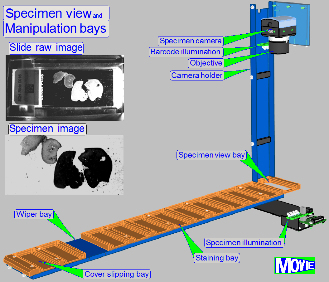
To execute the staining
procedure of the specimen, the position of the specimen in relation to the
glass slide is important. If more tissues are situated on the glass slide, all
parts have to be stained separately, because staining fluids are often very
expensive.
·
By making an image of the glass slide surface, the
position and size of the specimen’s area(s) are exactly known.
The barcode, assigned to the specimen contains information about the
specimen and staining values and staining procedures. The content is analyzed
by software and will be used to perform the staining procedure.
Main components are
·
Specimen illumination
·
Specimen camera
·
Objective
·
Barcode illumination
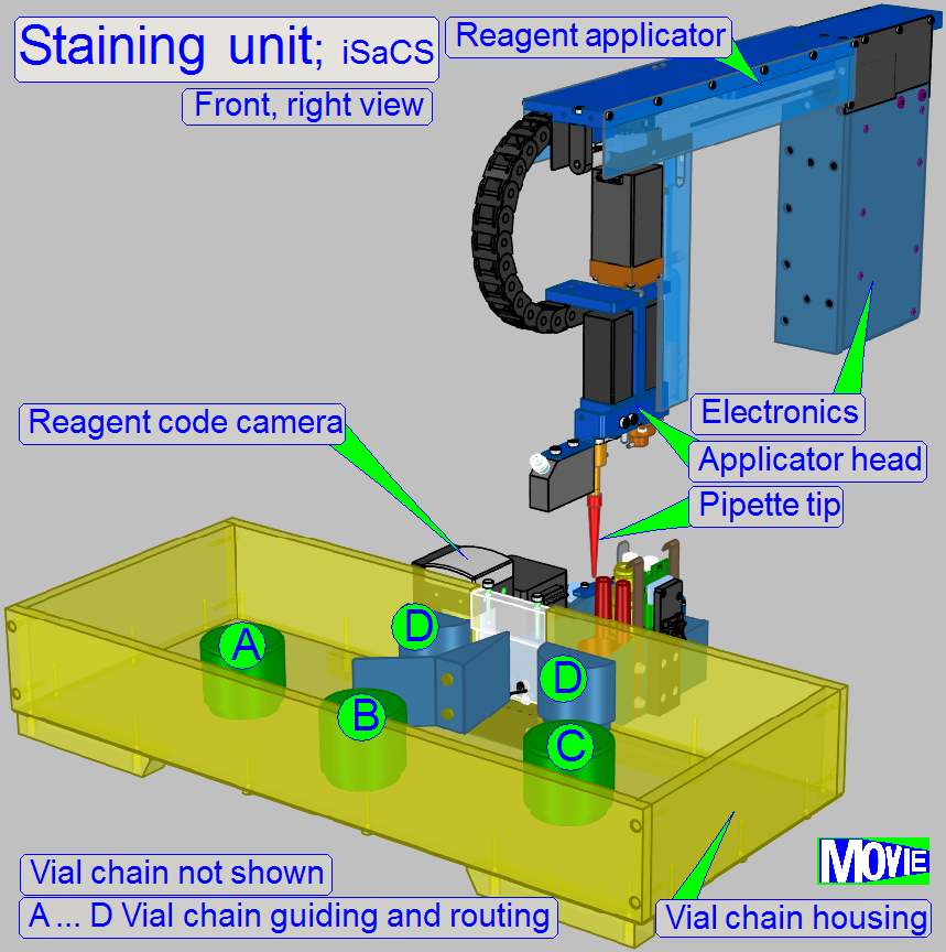
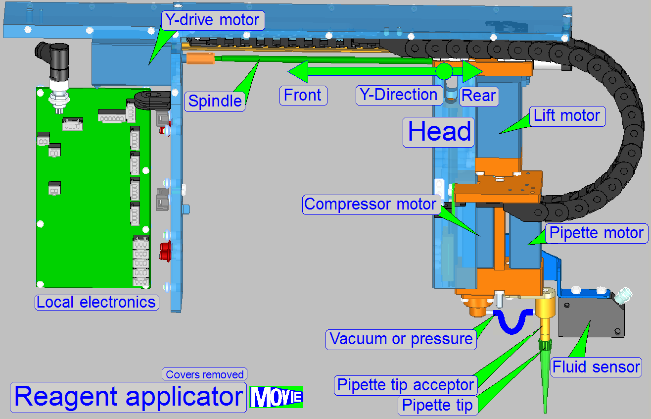
The staining unit is used to
apply the appropriate stain onto the specimen, so parts of the specimen will
fluoresce during the FL scan procedure. By using different fluorophores
(stains) different parts of the specimen will be seen in different colors. The
staining procedure of one specimen may be repeated several times, each
procedure with one stain.
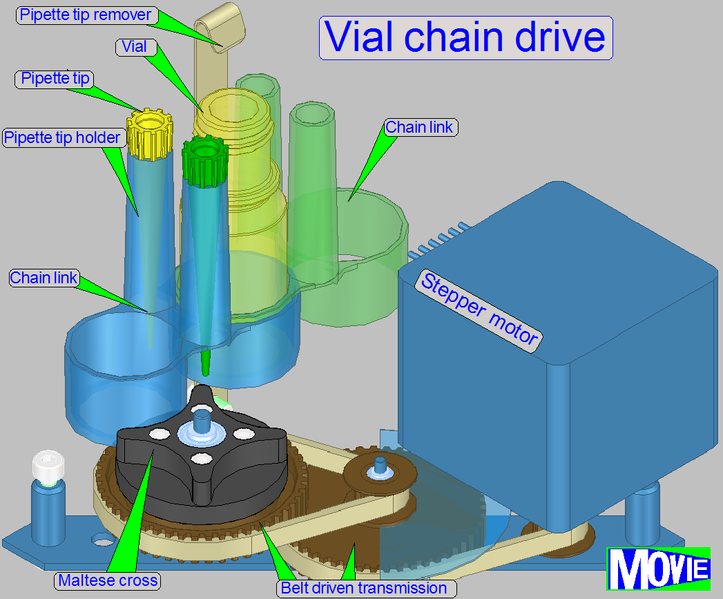
Main components are
·
Reagent vial
·
Vial chain
·
Vial chain drive unit
·
Reagent code reader
·
Reagent applicator
·
Pipette tip mover
·
Air pump
·
Pipette tip
![]() “Staining”;
“Staining”;
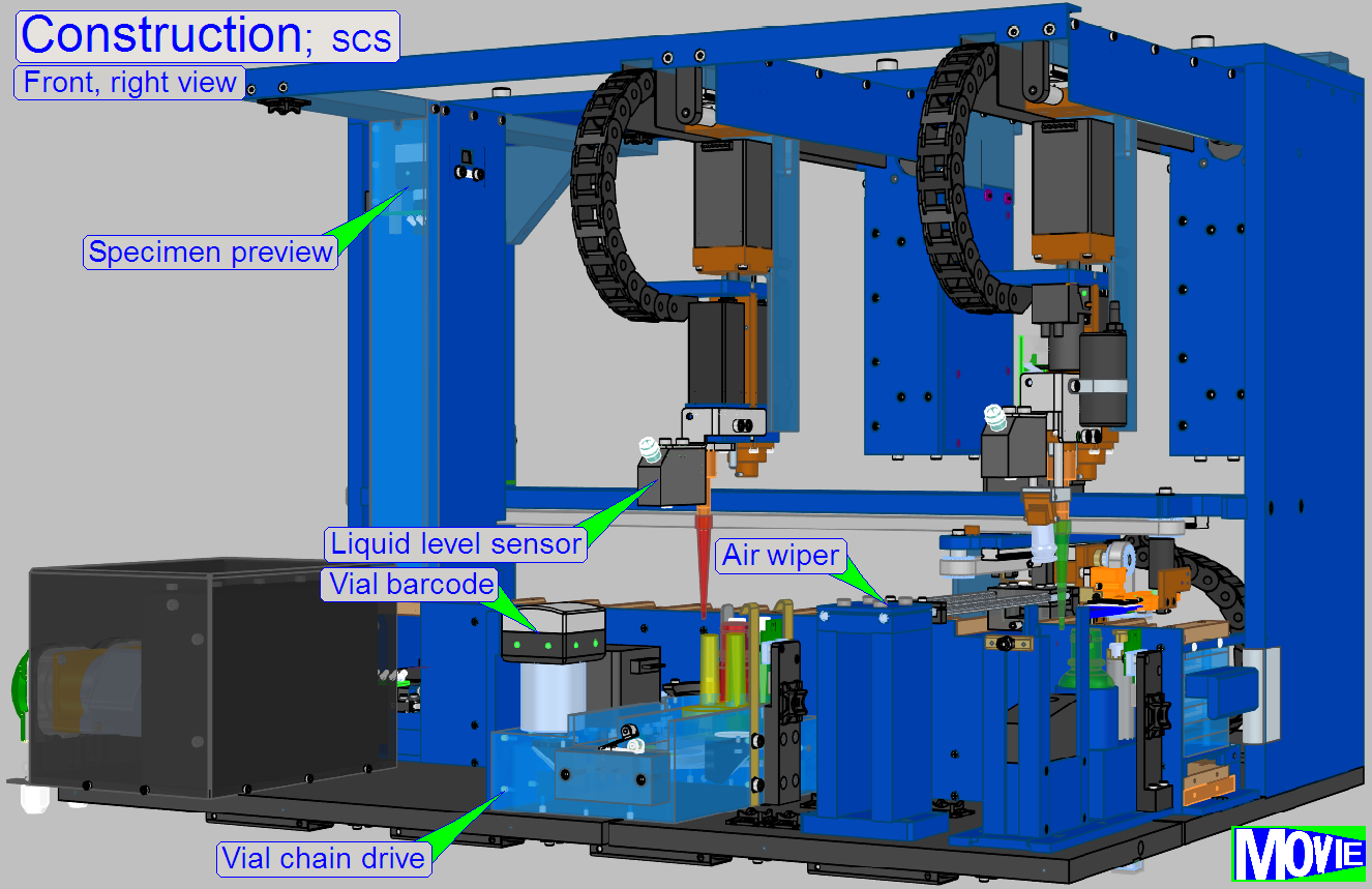
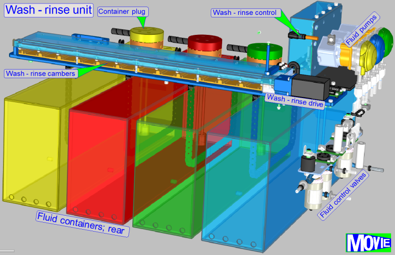 If the incubation time of one
staining procedure is over, the properties of the stain has to be fixed. The
fixing procedure is done with the washing fluid. Rinsing of the specimen
removes washing fluid residues. Residues of the rinsing process are removed
with the “Air wiper”; it is blowing up finest water droplets from the specimen
surface.
If the incubation time of one
staining procedure is over, the properties of the stain has to be fixed. The
fixing procedure is done with the washing fluid. Rinsing of the specimen
removes washing fluid residues. Residues of the rinsing process are removed
with the “Air wiper”; it is blowing up finest water droplets from the specimen
surface.
Main components are
·
Fluid containers
·
Container plug
·
Fluid pumps
·
Fluid flow control valves
·
Chamber selector
·
Wash-rinse chambers
Residues of the rinsing
process are removed with the “Air wiper”; it is blowing up finest water
droplets from the specimen surface.
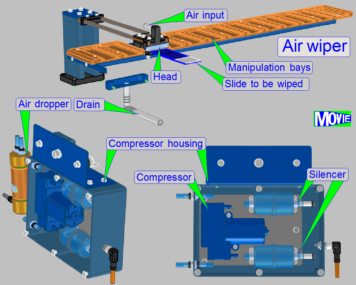
Main components are
·
Compressor
·
Silencer
·
Air wiper head with air input
·
Wiped fluid drain
·
Air dropper
·
Head holder
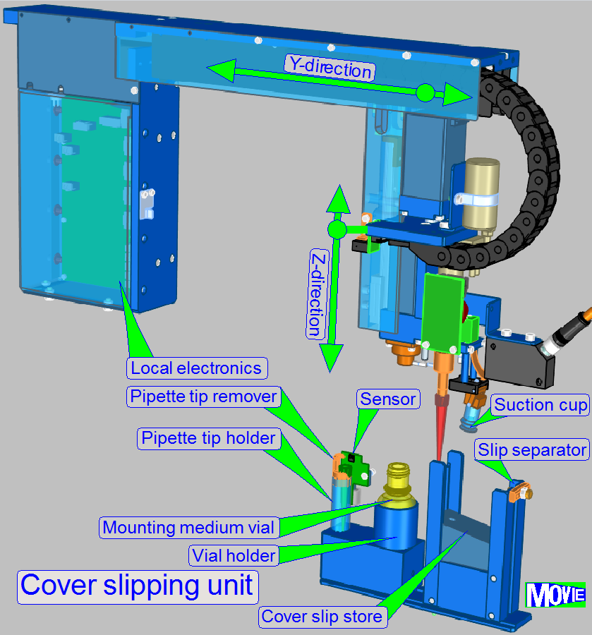 If the staining of
the specimen is finished, the specimen will be covered by a cover slip. The
mounting media is stored in a vial. The media applicator fills the pipette tip
with a defined quantity of the mounting medium and applies it onto the slide;
then, the suction cup takes a cover slip and places it correctly onto the
slide. By using defined pressure onto the coverslip, the coverslip will be
pressed onto the slide without remaining air bubbles.
If the staining of
the specimen is finished, the specimen will be covered by a cover slip. The
mounting media is stored in a vial. The media applicator fills the pipette tip
with a defined quantity of the mounting medium and applies it onto the slide;
then, the suction cup takes a cover slip and places it correctly onto the
slide. By using defined pressure onto the coverslip, the coverslip will be
pressed onto the slide without remaining air bubbles.
Main components are
·
Mounting medium vial
·
Pipette tip
·
Media applicator
·
Suction cup
·
Compressor