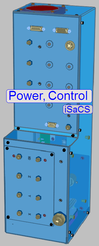
Power, control; iSaCS
For technicians and
partly for sales managers!
 The scanner
3DHISTECH iSaCS has modified power supply and electronics compare to the
Pannoramic 250. These modifications are required because the scanner is based
on a modular
The scanner
3DHISTECH iSaCS has modified power supply and electronics compare to the
Pannoramic 250. These modifications are required because the scanner is based
on a modular
·
The entire power unit has also got a separate housing
and is arranged in a tower; the so-called “Power tower”.
·
The internal construction and used components are
derived from the scanner Pannoramic 250 Flash and the Pannoramic Confocal.
·
Control of the staining and cover slipping units are
realized by the main control electronics and the local electronic units.
·
Power for the main electronics and connected
components is supplied from the Power tower.
·
The power supply of the Lumencor SPECTRA light engine
is realized with an external power supply.
·
Software-related settings and checks are based on the
software version 1.20.
Important remark
- After maintenance
or service and tests of the scanner are 100% finished, protective ground
connections and other safety regulations related to hazardous voltage,
accessible conductive parts and dangerous to life parts have to be checked
(again).
- For safety regulations
regarding human health and scanner functionality please refer to: Precautions
The power supply and control
electronics consist of the following components and units:
·
General
·
Scanner
·
Power distribution
and switch board
·
USB
Controller with EEPROM
Main control; Staining, Cover
slipping
 Main modifications in
relation to the modular
Main modifications in
relation to the modular
·
The iSaCS power supply is realized as an internal OEM power supply
module.
·
The power distribution
for momentarily unused units or all units in emergency situations (overheating)
can be
switched off by the PIC controller firmware.
·
The focus unit stepper motor was changed to a motor
with higher resolution (6400 steps / revolution).
·
Control of the objective
changer.
·
The X-Y-Z stepper motors do not contain control
electronics; the control
electronics for these motors was separated.
·
Independent temperature-sensing
and regulation by the control of the fan’s speed.
·
Further
sensors are implemented.
·
Illuminated logo.
Configure electronics components
Since the software version 1.15 the units of the
scanner are configured in the file “MicroscopeConfiguration.ini”, section
[Microscope].
The actual version of the
electronic components in the scanner iSaCS is defined as follows:
[Microscope]
SerialNumber=xxxxxx
MicroscopeType=3DMic10
MicroscopeSubtype=SCS
PreviewCameraType=CVrmc_m8_pPro
BarcodeReaderType=PreviewCamera
LoaderType=SL_1Mag_12Slide_Sensor_Horizontal
CameraChangerType=CC_None
ReflectorTurretType=RT_None
BrightfieldLightSourceType=RGBLedLight
ObjectiveChangerType=OC_2Pos
ObjectGuideXYZType=OGXYZ_FLASH4
FlashUnitType=FlashUnit_Type2; see
also: X-,Y-,Z-controller
NDFilterType=ND_None
PreviewLightType=PreviewLightUnitType_Type2
PowerSwitchBoardType=PowerSwitchBoard_Type1 see also: Power distribution
and switch board
Remark
To enable the X-,Y-,Z-controller:
FlashUnitType=FlashUnit_Type2
Actually, the most recent
“Type2” is used.
To disable the X-,Y-,Z-,controller:
FlashUnitType=FlashUnit_None
To enable the switch board:
PowerSwitchBoardType=PowerSwitchBoard_Type1
Actually, the most recent
“Type1” is used.
To disable the switch board:
PowerSwitchBoardType=PowerSwitchBoard_None
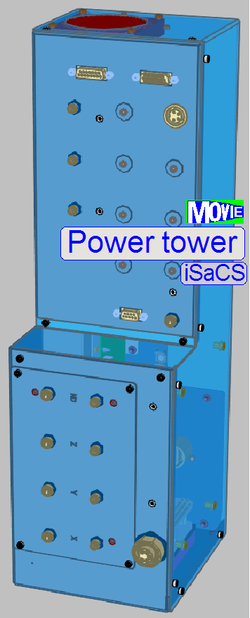
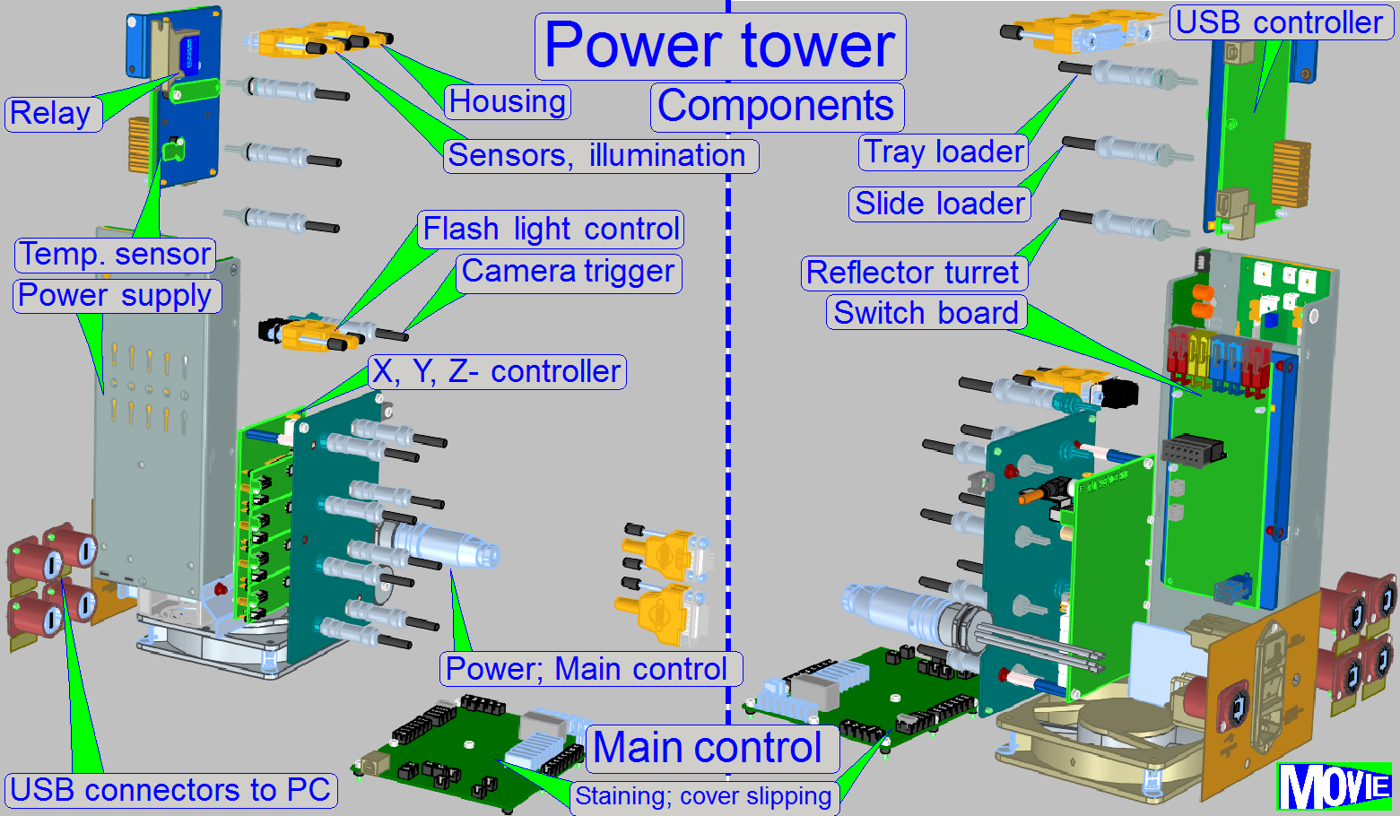
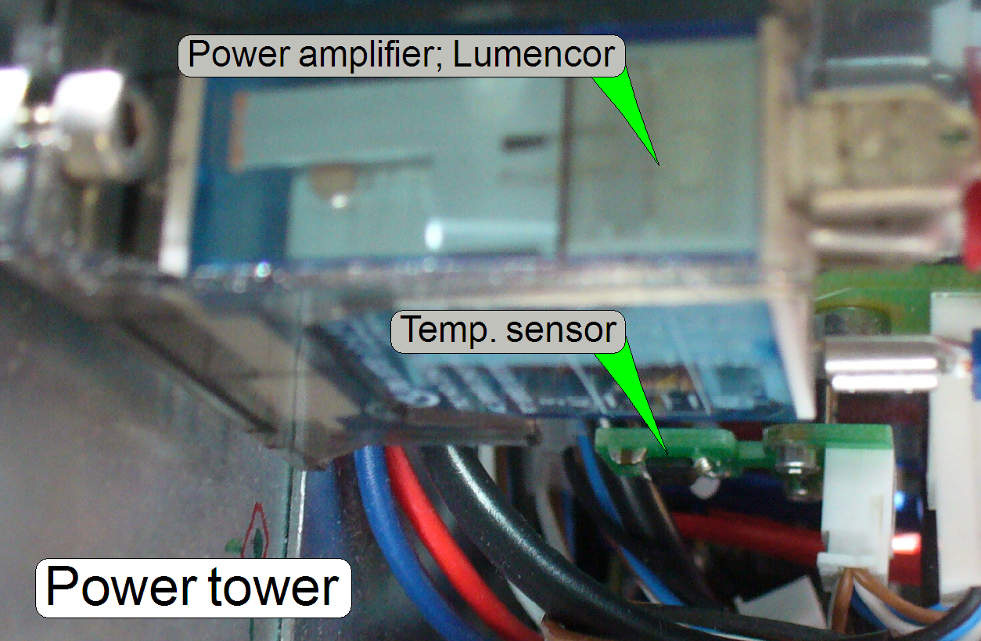
The main components of the
power supply and control electronics for the scanner are arranged in a “Power
tower”.
In the bottom part a fan with
particle filter is implemented, so the power supply and other electronic
components reach cooling.
A temperature sensor is
implemented to avoid probable overheating.
·
The entire power tower is mounted by 4 bolts to the
truss of the iSaCS.
More detailed information
about the internal construction can be found in the “Power
tower gallery”.
|
Connection |
Connector |
Identifier |
Pins |
||
|
Component |
|
+ |
- |
Signal |
|
|
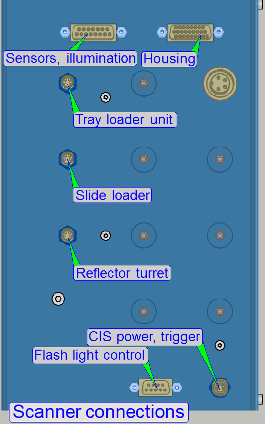
Preview BF illumination |
LBSL-1 |
10 |
11 |
|
|
|
|
|
12 |
13 |
|
|
|
|
|
14 |
15 |
|
|
|
Barcode illumination |
LCSL-1 |
16 |
17 |
|
|
|
Tray sensor |
HTSL-1 |
3 |
1 |
2 |
|
|
Slide sensor |
HSSL-1 |
6 |
4 |
5 |
|
Power distribution
and switch board
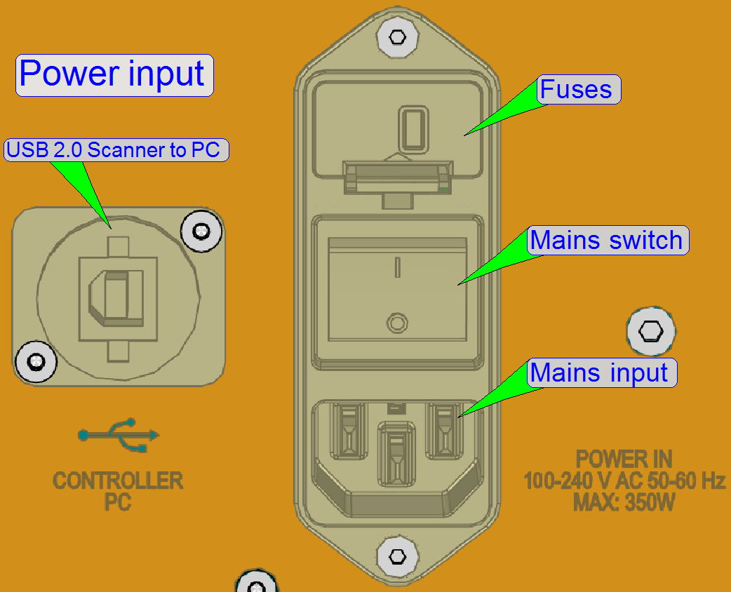
The power input connector and
mains switch consist of:
·
Power cord connector (Mains input)
·
Mains switch
·
Fuse housing with fuses
The double-pole mains switch disconnects
the mains power from the internal power supply.
Each pole is secured by a
slow-blow fuse of T3.15 A / 250V.
230V~
or 100V~
 The alteration of
the mains power input in the range from 100V~ to 240V~ is reduced to the use of
the appropriate mains power cable (additionally, various connector outlet
constructions are used in different countries worldwide).
The alteration of
the mains power input in the range from 100V~ to 240V~ is reduced to the use of
the appropriate mains power cable (additionally, various connector outlet
constructions are used in different countries worldwide).
If the mains power is changed
from 230V~ to 100V~ or vice versa, no alterations are required inside the
scanner. The change of the mains power is fully handled by the input voltage
range of the power supply; ![]() “Power supply TDK -Lambda“.
“Power supply TDK -Lambda“.
More information can be found
in the “Power input gallery” and the “Power input slide show”.
Check
or replace fuses
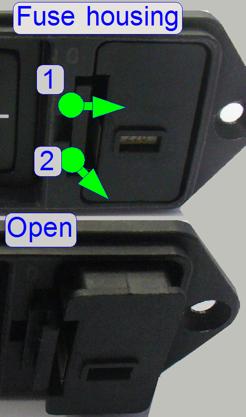 Disconnect the
power cable.
Disconnect the
power cable.
·
Open the fuse housing and remove the fuse container.
·
Push the fuse container lock guide (1) to the center
of the fuse container (for example with a flat screw driver).
·
Pull the container out (2) of the housing.
·
If the fuses are dismounted, use an Ohmmeter to check
the fuses.
·
If a fuse exchange is necessary, always use a
slow-blow fuse of T3.15 A / 250V (100V~ or 230V~ power input is unimportant).
More information can be found
in the “Power input gallery” and the “Power input slide show”.
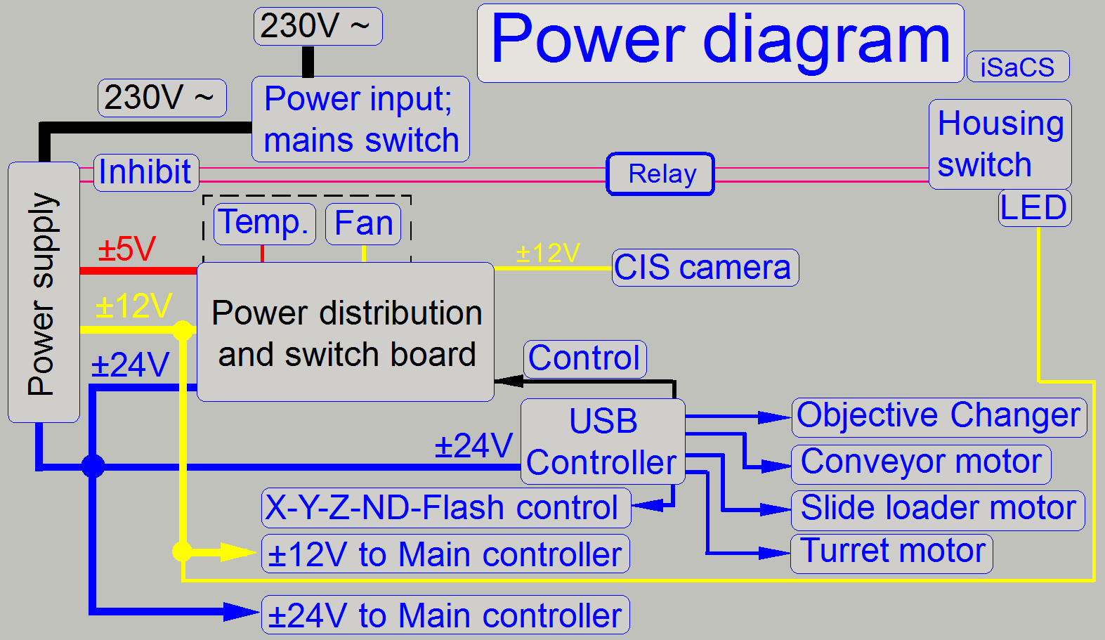
Power supply TDK -Lambda
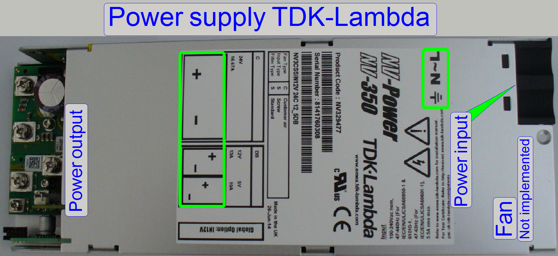

The internal OEM power supply
TDK-Lambda with an input voltage range of 90V~ to 264V~ AC, an input frequency
of 47Hz ~ 63Hz and output voltages of 5V-, 12V- and 24V- DC supplies the
internal units of the iSaCS with power. Inside the controller units (USB, X-,
Y-, Z-motor controller, power distribution board and some stepper motors) a
local power supply is located and this create further, required voltages.
·
The power supply is short circuit-protected.
·
The “Housing Switch” is used to switch off the entire
scanner if mechanical malfunction or other emergency situation occurs.
·
If the input voltage is changed from 230V~ to 100V~ or
vice versa, no alteration is required inside the scanner.
Remark
The fan of the power supply
is removed in the iSaCS; the cooling of the components is done by the central fan of the power tower.
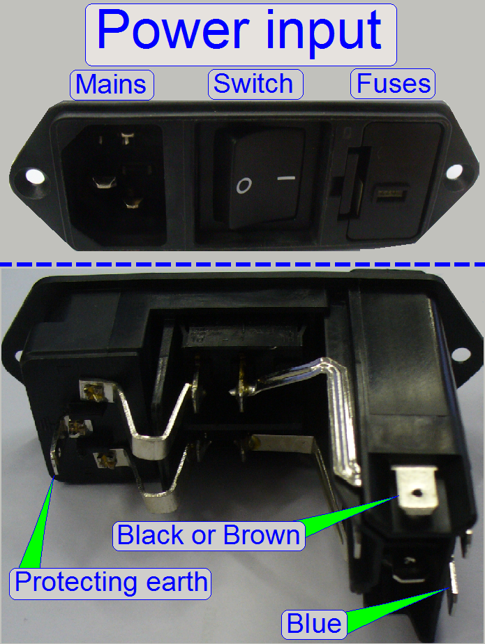
Power input
·
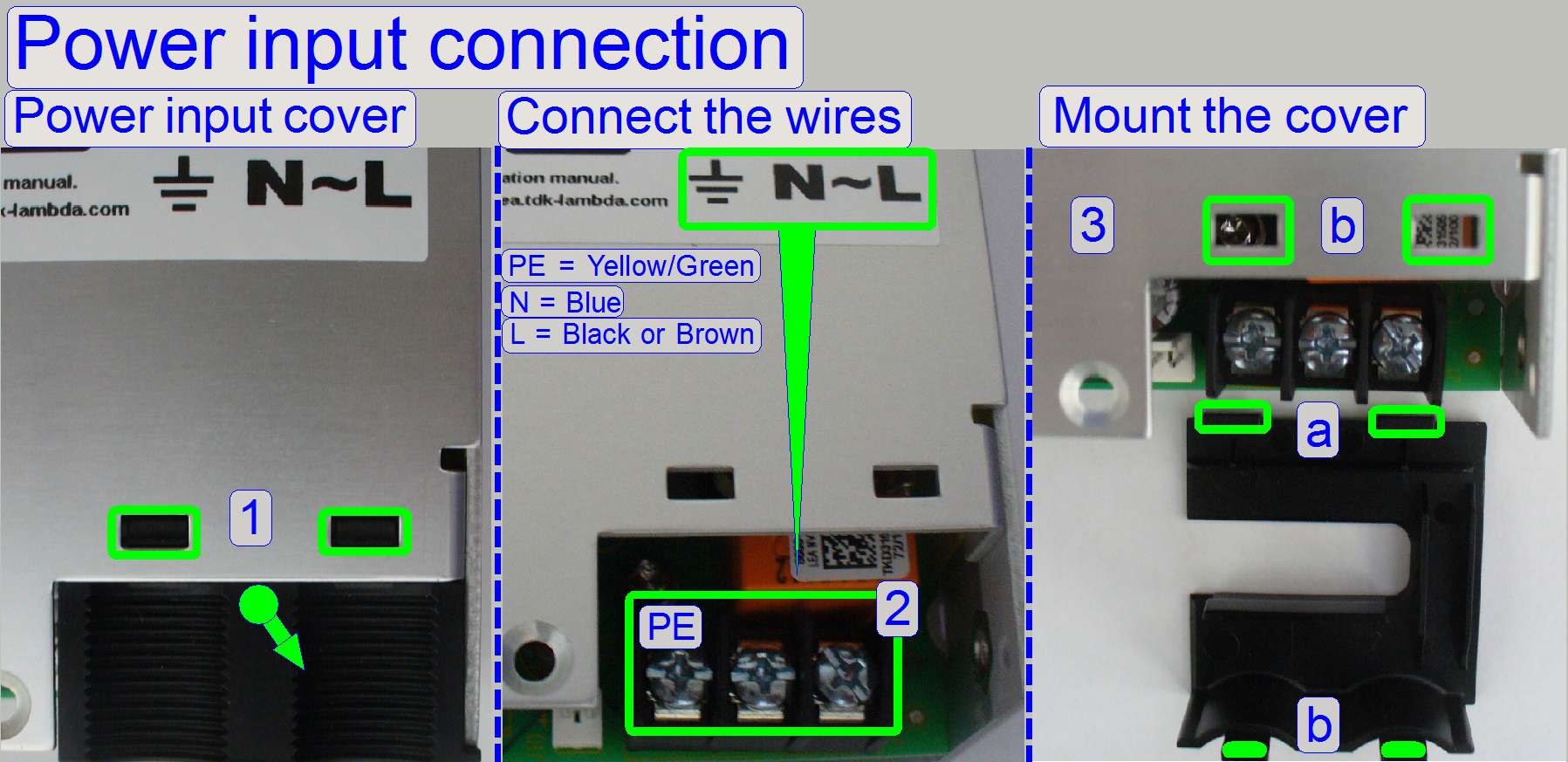 Press the power
input cover a bit downward until the clamps (1) are disconnected from the upper
housing part and remove the cover.
Press the power
input cover a bit downward until the clamps (1) are disconnected from the upper
housing part and remove the cover.
·
Connect the power wires as shown (2).
·
Fit the parts (a) into the slots of the base cover and
the clamps (b) into the appropriate slots of the top cover.
![]() “Installation manual” (in more languages); stored in this
description
“Installation manual” (in more languages); stored in this
description
Output
voltages; power
·
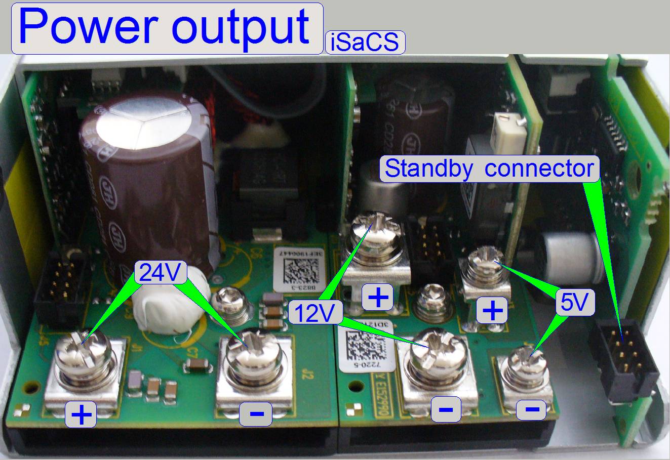 5V- /10A DC
·
12V- / 13A DC
·
24V- / 18.75A DC
The outputs are short
circuit-protected and are ground independent (the minus pole is not connected to GND) so each
voltage has a plus (+) and a minus (-) pole.
![]() Power_supply_tdk_Lambda_Data_Sheet.pdf (stored) and
Power_supply_tdk_Lambda_Data_Sheet.pdf (stored) and
Power_supply_tdk_Lambda_App.
Notes.pdf (stored)
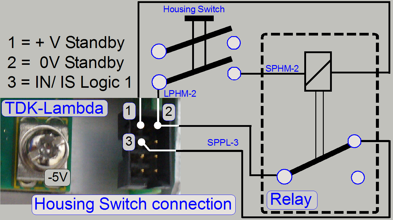
Housing Switch and standby
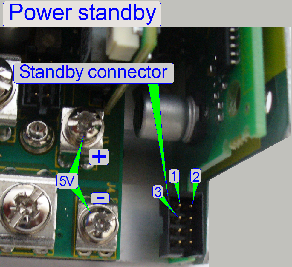 The Housing Switch
inhibits and stops the switching power supply by the help of a relay, but the
mains voltage of 100V~ or 230V~ is not interrupted; the power supply goes to
standby.
The Housing Switch
inhibits and stops the switching power supply by the help of a relay, but the
mains voltage of 100V~ or 230V~ is not interrupted; the power supply goes to
standby.
By shorting the pins “
If there is no connection
between the two pins (or the standby option is not used), the power supply is
running continuously.
·
These two pins will be shorted via a relay, if the
“Housing Switch” is active and closed.
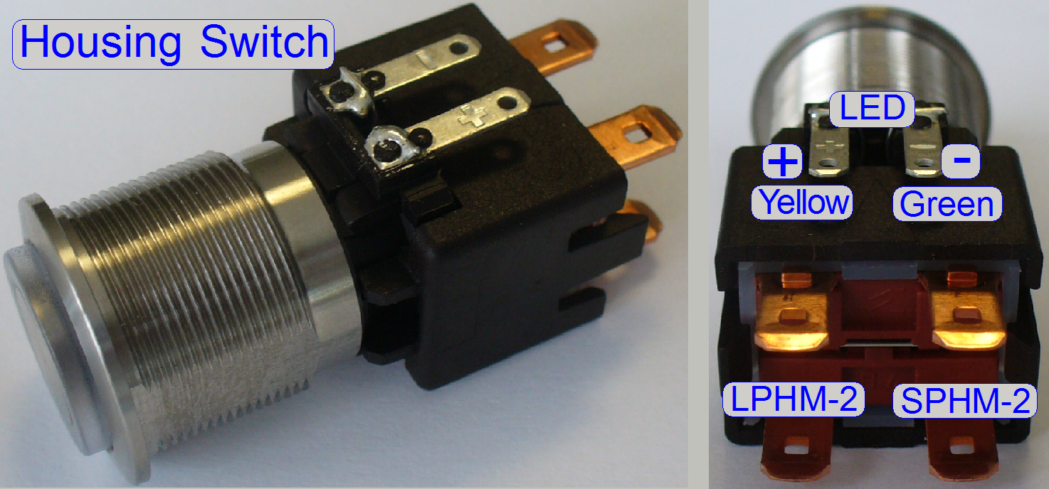
Housing Switch
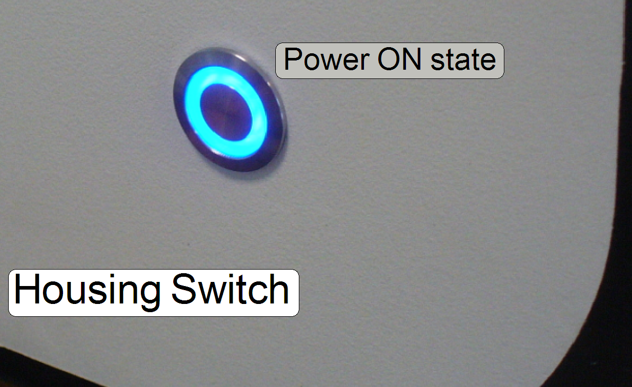 The Housing Switch
is situated in the left handed side wall of the scanner and is used to inhibit the
power supply. The power distribution is interrupted and all movements are
stopped immediately.
The Housing Switch
is situated in the left handed side wall of the scanner and is used to inhibit the
power supply. The power distribution is interrupted and all movements are
stopped immediately.
·
If the power is supplied again to the scanner, the software has to be
started again.
![]() “Housing
Switch” and “Power LED”.
“Housing
Switch” and “Power LED”.
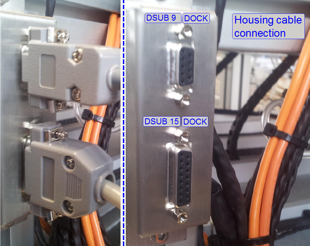
Housing
connectors
Power distribution and
switch board
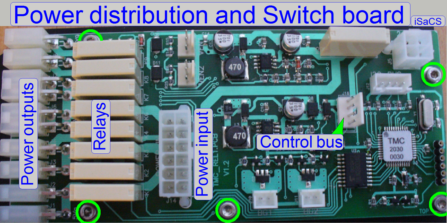
The power outputs can be
switched by software; so momentarily unused units can be switched off, or if
any emergency event occurred, all outputs may be disabled.
The outputs are switched by
the use of relays.
The communication between
software and the power distribution board is realized with the control bus
connector; this is connected to the USB controller and is used to switch on /
off the power outputs and to transfer status information to the USB-controller.
The temperature sensor input
controls the fan output directly, without any scan software control, bat the
temperature value and the fan speed can be read from the software; see also the
service program, Low level service, power supply. The fan speed is controlled
via the PIC on this switch board, depending on the sensed temperature value.

Enable or disable of the switch board
For technical enhancements
and upgrades, the type of the entire “Power distribution & switch board”
can be defined or the board might be disabled.
The relevant parameter and
value is found in the section [Microscope] of the file “MicroscopeConfiguration.ini”.
To enable the switch board:
PowerSwitchBoardType=PowerSwitchBoard_Type1
Actually, the most recent
“Type1” is used.
To disable the switch board:
PowerSwitchBoardType=PowerSwitchBoard_None
 Usually, the board is
enabled.
Usually, the board is
enabled.
If the entire “Power distribution
and switch board” is disabled, the power supply for the camera and all other
connected units is disabled; the scanner will not start correctly or the
powering of the appropriate units have to be realized otherwise; e.g. with
external power supplies.
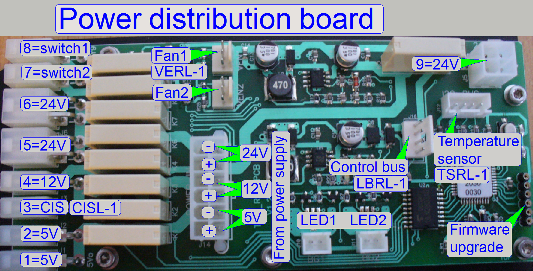
1= reserve 5V- output
2= reserve 5V- output
3= Power output 12V- CIS main camera; CISL-1
4= Power output 12V-
5= Power output 24V-
6= Power output 24V-
7= reserve switch1
8= reserve switch2
9= reserve 24V- output
5V= Power input from the
TDK-Lambda power supply
12V= Power input from the
TDK-Lambda power supply
24V= Power input from the
TDK-Lambda power supply and LPPL-1
The switched outputs are
ground independent (the minus pole is not connected to GND) so each voltage has
a plus (+) and a minus (-) pole.
The board is found in the
“Power tower” see also: Distribution
and switch board
Connectors Fan1 and Fan2
Via the connector “Fan
Temperature sensor input
The temperature sensor input
is an I2C bus input and the temperature sensor is connected via the
line “TSRL-
 The temperature
inside the Power tower is sensed via a temperature sensor by the help of the
PIC on the switch board.
The temperature
inside the Power tower is sensed via a temperature sensor by the help of the
PIC on the switch board.
Probably errors may be:
·
Temperature sensor is not connected; any wire is
broken or has no contact.
·
Sensor is defective.
·
Power distribution and switch board is defective.
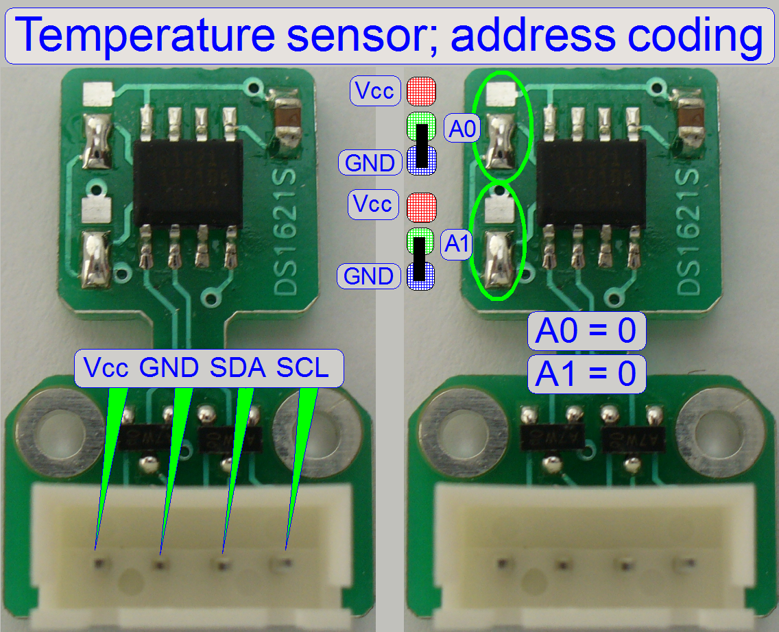 Temperature sensor;
TSRL-1
Temperature sensor;
TSRL-1
The temperature inside the
Power tower is sensed via a temperature sensor by the help of the PIC on the
switch board.
Probably errors may be:
- The
temperature sensor is not connected; any wire is broken or has no contact.
- Sensor is
defective.
- Power
distribution and switch board is defective.
- Wrongly
defined address of the sensors
(after exchange).
Voltage: 3.6V ~ 5.5V max
Data sheet: DS1621S
Temperature sensor, fan and fan control
 Because the fan of
the power supply is removed and cameras needs cooling (their temperature must
not exceed 60º C (140º F)), temperature sensing and active
cooling of the scanner is required.
Because the fan of
the power supply is removed and cameras needs cooling (their temperature must
not exceed 60º C (140º F)), temperature sensing and active
cooling of the scanner is required.
The sensed temperature value
is used to control the speed of the fans directly; without any interaction of
the scan software “SlideScanner.exe”.
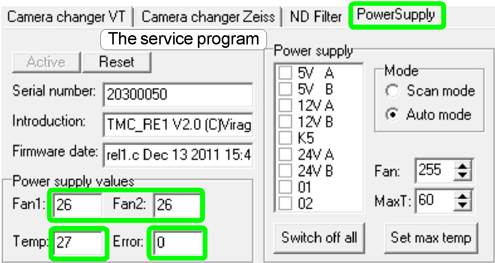
In the service program, the
sensed temperature is shown in [ºC], the fan speed is shown in a value
between 1 and 255; 255 is the full speed of the fan.
·
The sensed temperature value and the fan speed can be
read with the service program any time.
If the field “Error” is
different from zero, a HW error exists in the temperature sensor and fan
control electronics; depending on the error code.
Error codes
16 Fan error; the
spinning speed of the fan is too slow; the fan blades moving too strong; they
have too much resistance in the bearing.
32 Fan error; the
blades of the fan are not spinning; check cabling, connection; try to rotate
the fan blades manually; check for any mechanical reason also.
64 The temperature of
60º C (140º F) reached; check and clean the dust filter of the fan;
check the fan’s connection and the movement of the blades also.
128 Power tower
overheated; the relays are switching off; the power to the connected units is
interrupted; the temperature reached 70º
C.
·
Because the error bits are arranged in a byte, other
values are possible if more errors existing at the same time; e.g. 96= 64 + 32.
·
If the units are switched off by overheating, the scan
software SlideScanner.exe shows the error message
“Error occurred”
and stops working.
 The spinning of the
blades is recognized by the PIC.
The spinning of the
blades is recognized by the PIC.
Probably fan errors may be:
·
The signal of the fan spinning sensor (situated inside
the fan) is not recognized by the fan control logic, because the fan is not or
not well connected; the fan blades does not rotate (any mechanical or cabling
reason) or the fan is defective.
·
If the fan speed is too slow please check and clean
the dust and particle filters or the fan blades moving too strong; they have
too much resistance in the bearing (fan goes defective).
·
The power distribution and switch board is defective.
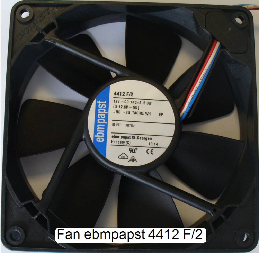
![]() “The
fan”
“The
fan”
The Fan with dust filter is
found in the “Power tower” from beneath; see also: Construction_2
Nominal “wire to board”
connections
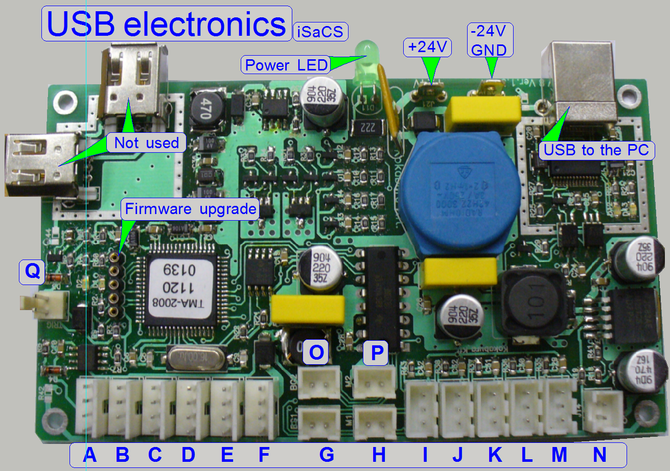
The USB controller connects,
supplies and controls all the addressable units and outputs; these are:
·
Power distribution
& switch board
·
Objective changer
unit (OC)
·
The USB controller gets its +-24V power directly from
the tdk lambda OEM
power supply.
The USB controller receives
the command for the units from the program SlideScanner.exe (the scan program)
or the SlideScannerService.exe (the service
program) via the USB control port of the PC and the USB cable.
All units contain separate
electronics and are connected via a bus system. To differentiate the units,
connected to the USB controller, all stepper motor electronics and the
unit-controller as well has an address.
Each data transfer starts with the specified address for the unit and is listen
by all units at the same time, but only this unit receives the message, which
internal address and the message address is identical. The stepper motor
electronics can receive commands (number of steps to go and direction) and can
send status information (desired position reached and the status of the sensors
Home1 and Home2). The status information
is sent via the USB cable to the software, hereby the address of the unit is
used also.
With this solution it is
possible to change the “Hirschmann” connection with another “Hirschmann” cable
(Connectors A ...F; e.g. for fault detection) without any risk or functional
restrictions. The label of the cable for digital electronics has no reason in
functionality; it differentiates the cables from each other instead, because
some cables are shorter than others.
Important
The construction of the controller powering on the board does allow the
drive of maximal 3 stepper motors at the same time!
·
Please take this into account, if you
are working with the service program and the batch test program module!
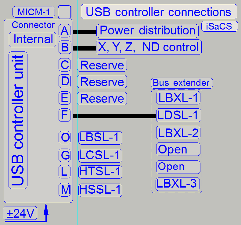
 Nominal
“wire to board” connector positions
Nominal
“wire to board” connector positions
A = LBRL-1 Power distribution and switch board
B = LBFL-1 X-Y-Z-motor control
C = Reserve
D = Reserve
E = Reserve
F = LISL-1 Bus extender TMC_LIN 1 (1)
G = LCSL-1 Barcode illumination; CF01D
H = Reserve
I = Reserve
J = Reserve
K = Reserve
L = HTSL-1 Tray sensor = TMC-HAL1(2) CF01E
M = HSSL-1 Slide sensor = TMC-HAL1(1) CF01F
N = Reserve
O = LBSL-1 Brightfield preview (background)
illumination; CF01A
P = Reserve
Q = Reserve
·
The USB controller gets its +-24V power directly from the tdk lambda OEM
power supply; the minus pole (-) is connected to the pin, named as GND!
The USB controller unit is
found in the “Power tower” see also: USB
and Construction_3
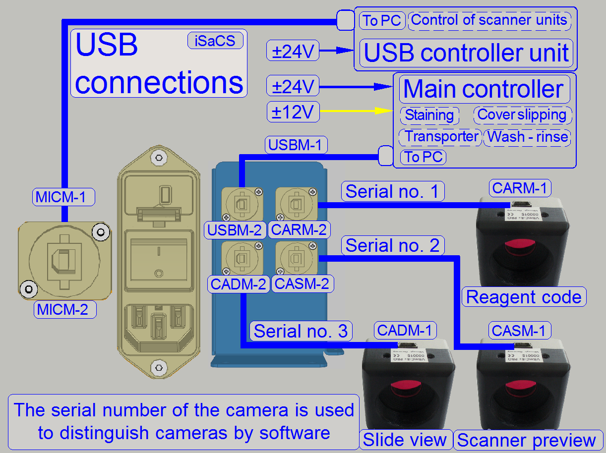
USB to PC
The USB connection
to the rear connector is realized with an internal USB cable, see also: “USB” and “Left side wall”
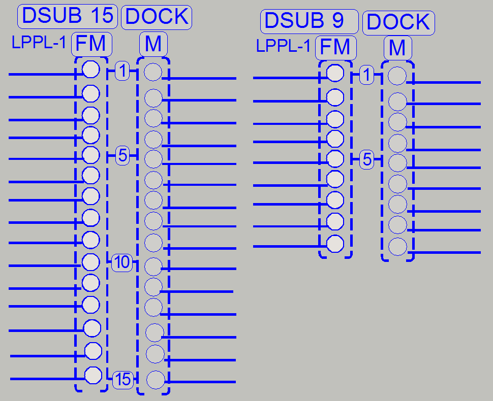
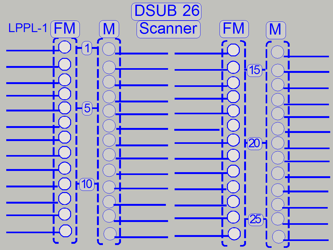
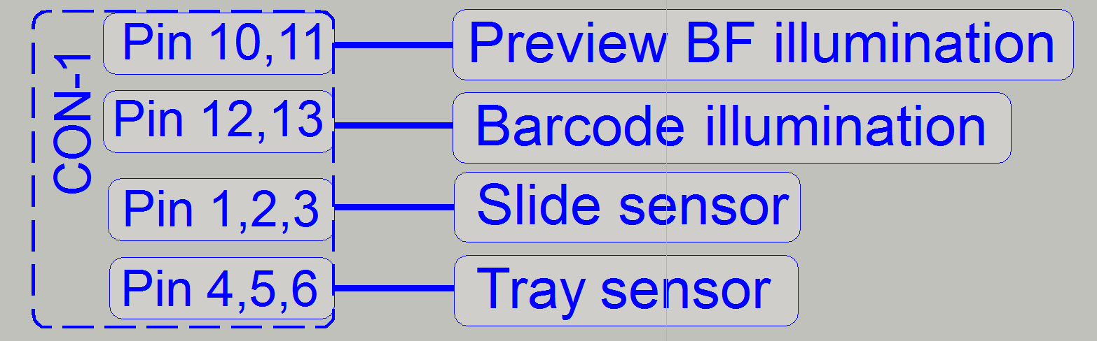
Output and sensor connections
|
Connection |
Connector |
Identifier |
Pins |
||
|
Component |
|
+ |
- |
Signal |
|
|
Preview BF illumination |
LBSL-1 |
10 |
11 |
|
|
|
|
|
12 |
13 |
|
|
|
|
|
14 |
15 |
|
|
|
Barcode illumination |
LCSL-1 |
16 |
17 |
|
|
|
Tray sensor |
HTSL-1 |
3 |
1 |
2 |
|
|
Slide sensor |
HSSL-1 |
6 |
4 |
5 |
|
·
The length of the cables is so
dimensioned, that only the specified unit can be reached easily.
The addressable units are also
connected via the “Bus extender” because the number of connected units
increased. The bus contains the power supply for the unit (24V-) and the serial
bus (I2 C). Via the
serial bus the connected units are addressed, receive command and control
information and returns status information.
Each connected unit contains
a local power supply to create further, required voltages.
Nominal
connections of TMC LIN1
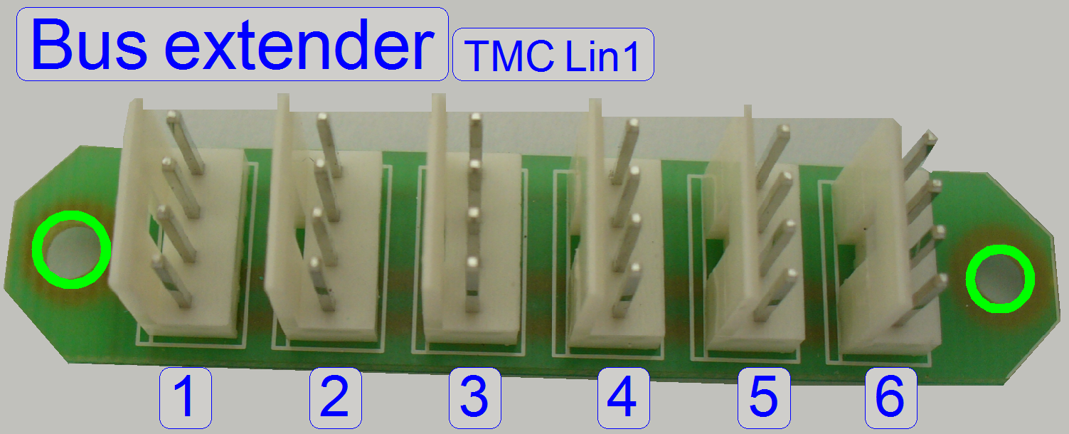 1 = LXBL-1 Tray
loader motor
1 = LXBL-1 Tray
loader motor
2 = LISL-1 Connector
“D” of the “USB
controller”
3 = LBXL-2 Slide
loader motor
4 = Open
5 = Open
6 = LBXL-3 Turret
motor
·
Positions may be changed without any functional risk
or restrictions!
The Bus extender is found in
the “Power tower” see also: “Bus
extender”
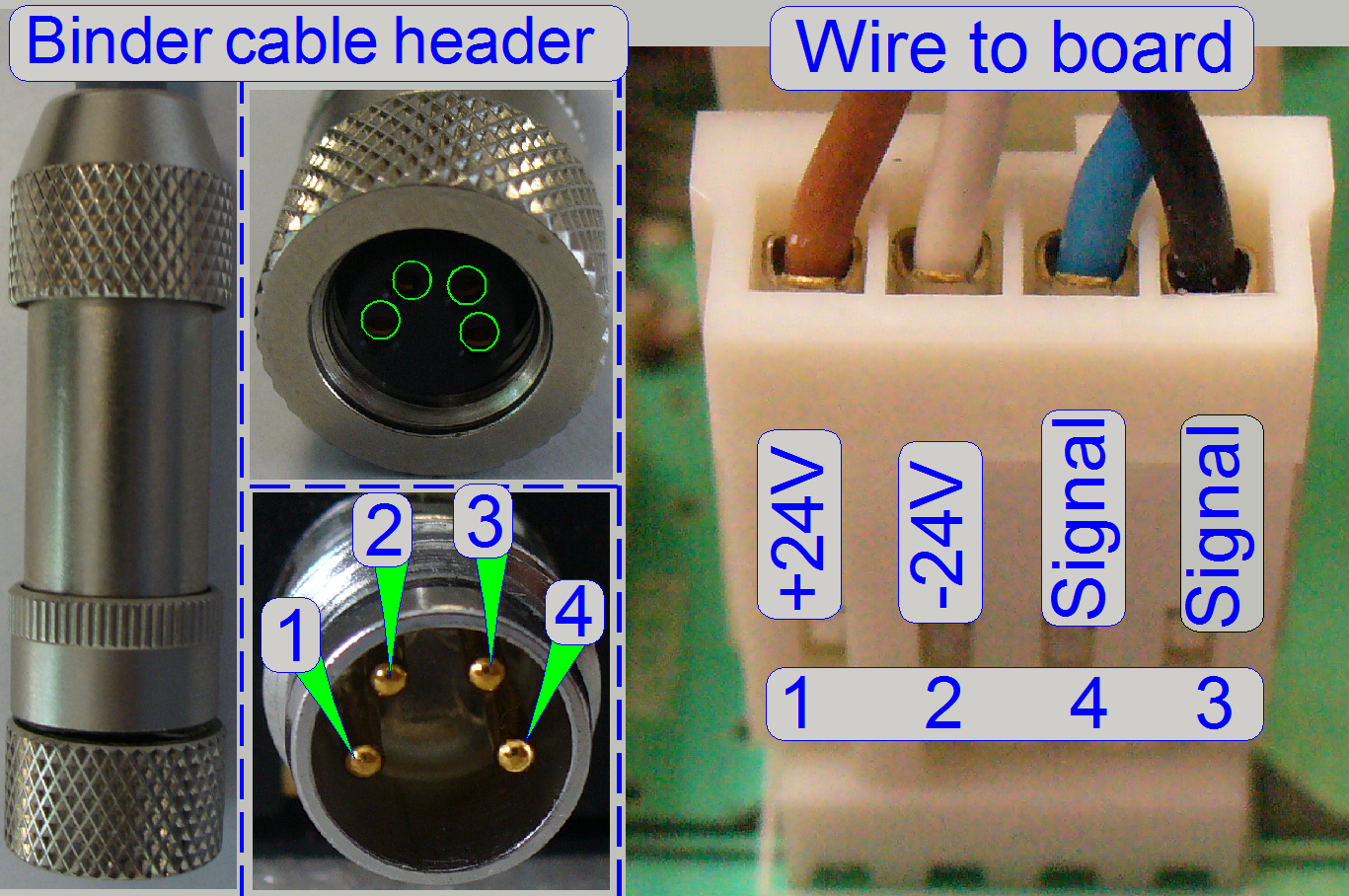
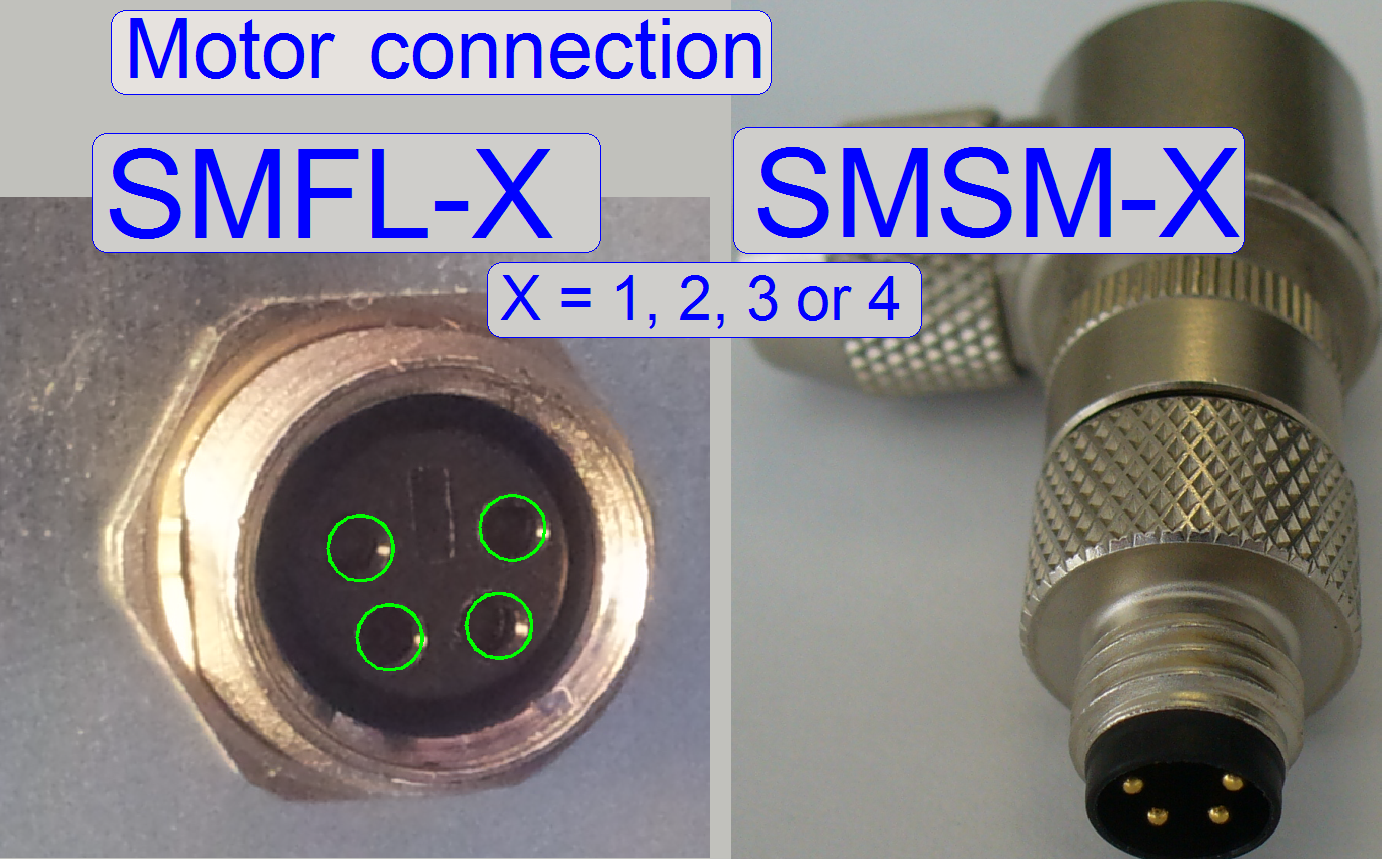
The addressable units are
connected with the “Binder” connector (except the Power distribution and switch
board); the connection is secured with a knurled nut. On the other end of the
cable a “wire to board” connector is used.
Important
Please do not use pliers to
loosen or tighten the cable header lock nut. If there is too much force used on
the connectors, the soldering of the connector may be destroyed and broken and
the appropriate motor or unit will not work.
|
Addresses of scanner
units |
||
|
Unit |
Address |
Type |
|
X-Y-Z
control |
00 |
C_P |
|
USB-controller |
01 |
All |
|
DC-controller |
02 |
P_S_M_D
|
|
X-motor |
03 |
S_M_D |
|
Y-motor |
04 |
S_M_D |
|
Z-motor |
05 |
S_M_D |
|
Turret
unit |
06 |
S_M_P |
|
Tray
loader motor |
07 |
M_C |
|
Slide
loader motor |
08 |
M_C |
|
Objective
changer |
09 |
C_P_S_M
|
|
Camera
changer |
10 |
P |
|
RGB
illumination |
11 |
C |
|
Reserve |
12 |
|
|
Immersion
liquid unit |
13 |
C |
|
Mechanical
shutter |
14 |
C |
|
Switch
board |
15 |
C_P |
|
Legend:
C=Confocal; P=P250; S=SCAN; M= |
||
The addresses are
used by the scan program and the service program to select the unit; these addresses
are programmed into the specified unit and can be changed via special software only. It is important,
that none of these addresses should exist twice inside of one Pannoramic
scanner, otherwise command and status mismatch occurs.
If data transfer
is in progress, all addressable units listen to the address of the data stream.
If the address of
the unit is identical with the address of the data stream, the addressed unit is
found and this receives the information.
·
The length
of the cables is so dimensioned, that every bus connector may be reached with
any bus cable header.
·
Positions of the bus cables may be changed without any
risk or functional restrictions; e.g. for fault detection!
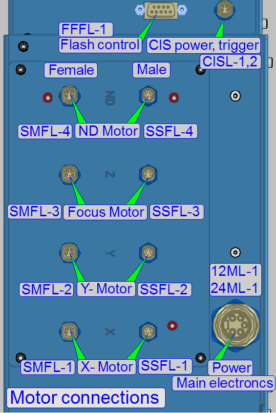
X-Y-Z-ND-motor and Flash
light control
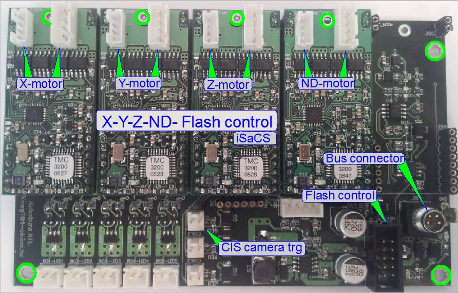
Because in the P250 the
ND-motor is additionally implemented, the Flash light control has to be
resolved and the focus motor is of a different type, a new electronics box was
implemented.
The unit realizes the
control, connections and interfacing of the following units:
·
X-motor
·
Y-motor
·
Z-motor (focus)
·
ND-motor
·
Flash light
control for brightfield scan
·
Trigger connection of the CIS-camera
·
The power supply and the control of the addressable
unit are realized with the “Hirschmann” connector (Bus connector).
·
The X-, Y-, Z- and ND-stepper motor control
electronics is realized with the appropriate module; these motors itself does
not contain control electronics.
·
The motor modules are all from the same type and are
interchangeable without address modifying.
Flash light control
The arc frequency of
the Flash light source is controlled via the software.
The connector
“CIS-camera trg” is software controlled and defines the shutter time and pulse
width for the CIS-camera.
Darkfield illumination connector
·
The two connectors “DF illumination” provide the power
for the darkfield illumination and are interchangeable; the intensity can not
be affected.
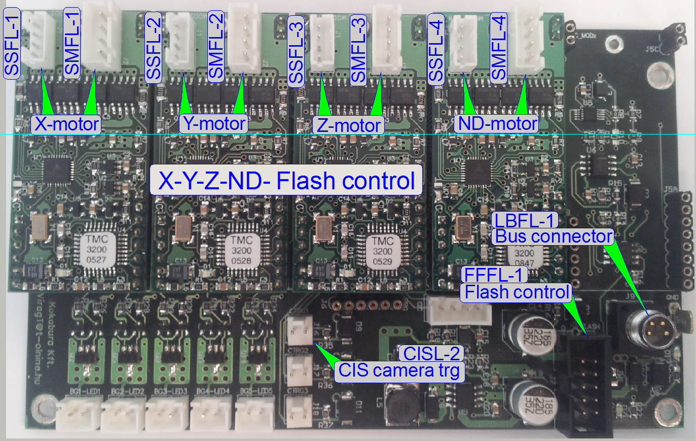
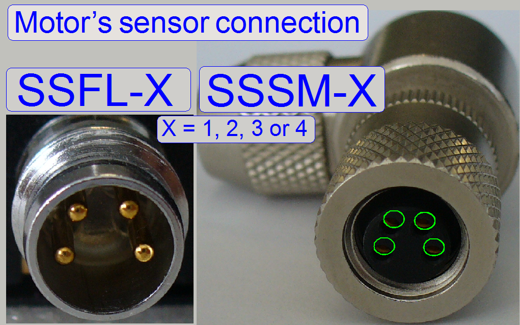
The wires of the appropriate
stepper motor as well as the wires of the sensors are directly connected to the
electronics via the motor cable headers.
The construction of the
connectors does not allow an interchanging of the two cables to each other, but
the motor can be connected to another module; e.g. for fault detection.
·
The sensors Home1 and Home2 are also connected via the
motor headers.
 Important
Please do not use pliers to
loosen or tighten the cable header lock nuts. If there is too much force used
on the connectors, the soldering of the connector may be destroyed or broken
and the appropriate motor will not work or may working very noisy.
Hint
·
For test purposes and fault detection, the motor cable header pair may be
connected to another motor output; e.g. the X-motor headers are connected to
the Y-motor output.
·
In this example, the service program Y-direction will be used to move
the X-stage!!
·
Before SlideScanner.exe will be started, the motor cable headers have to
be connected to their original, correct motor connection!
Addresses
of staining and cover slipping control
|
Addresses SC units |
||
|
Unit |
Address |
|
|
Main control |
5 |
|
|
Transporter |
2 |
|
|
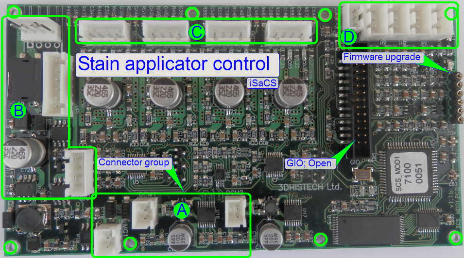
Stain applicator |
1 |
|
|
Reagent chain |
4 |
|
|
Cover slipping |
0 |
|
|
Wash rinse |
3 |
|
|
|
||
Because the entire staining
and cover slipping part of the iSaCS is controlled via an USB cable to the PC, different
from the scanner part, and the staining and cover slipping part is divided into
several control electronics, addresses are used to distinguish the data stream
for the controllers.
·
The addresses are programmed into the unit, so each unit
is unique in the system, nevertheless several controllers are from the same
construction!
To
increase the manageability of the numerous connectors, these are grouped
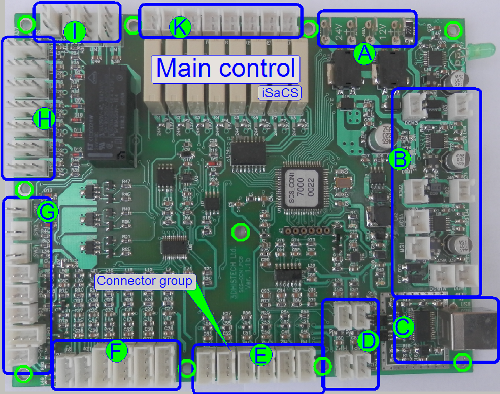
·
A = Power supply
·
B = Housing
·
C = USB communication
·
D = Plug sensors
·
E = Container position
·
F = Optical sensors
·
G = Illuminations, Switches
·
H = Local bus
·
I
= Miscellaneous
·
K = Relay controlled outputs
·
To find the description
of connected units for the cable labels (Name), click the group link
|
Name |
Type |
Group |
Source or Target |
Description |
|
±12V |
Power |
Power tower |
Via connector
“Power Main electronics” |
|
|
±24V |
Power |
|||
|
ASHM-1 |
Container door |
Solenoid latch; locks the
lower right cover |
Latched “Off” Released “On” |
|
|
USBM-1 |
USB bus |
USB I/O board on the left
side |
Software communication |
|
|
HPTM-1 |
Pressure sensor |
Plug “Wash buffer” |
Via these container
sensors, the fluid level is recognized. |
|
|
HPTM-2 |
Pressure sensor |
Plug “Distilled water” |
||
|
HPTM-3 |
Pressure sensor |
Plug “Hazardous waste” |
||
|
HPTM-4 |
Pressure sensor |
Plug “Non-hazardous waste” |
||
|
HATM-1 |
Hall sensor |
Position “Wash buffer” |
Container position
recognized, if the sensor shows active state. |
|
|
HATM-2 |
Hall sensor |
Position “Distilled water” |
||
|
HATM-3 |
Hall sensor |
Position “Hazardous waste” |
||
|
HATM-4 |
Hall sensor |
Position “Non-hazardous
waste” |
||
|
IRCM-1 |
Optical sensor |
Pipette tip sensor |
|
|
|
IRRM-1 |
Optical sensor |
Reagent changer sensor |
|
|
|
IRFM-1 |
Pipette tip checker |
IR sensor cover slipping |
Mounting medium |
|
|
IRMM-1 |
Optical sensor |
Slide handling |
|
|
|
IRCM-1 |
Pipette tip checker |
IR sensor staining |
Used pipette tip |
|
|
ITFM-1 |
Slide sensor |
IR sensor in the slide
mover |
Present or absent |
|
|
SIFM-1 |
Switch Slide rack |
Micro switch in wash-rinse
unit |
Rack inserted corectly |
|
|
SCFM-1 |
Switch Reag. tray |
|
|
|
|
STHM-1 |
Tank switch |
|
|
|
|
LTDM-1 |
illumination |
DF illumination for slide
image |
Front: “On” or “Off” |
|
|
LMDM-1 |
illumination |
DF illumination for slide
image |
Rear: “On” or “Off” |
|
|
LLDM-1 |
illumination |
For barcode in slide image |
“On” or “Off” |
|
|
LZHM-1 |
“On/Off” front |
Main switch for
the entire iSacs |
Front of upper
cover |
|
|
SZHM-1 |
“On/Off” front |
|||
|
LBRM-1 |
Vial chain |
Control board “Vial chain
ontrol” |
Internal control bus |
|
|
LBWM-1 |
Wash-rinse |
Control board “Wash rinse” |
Internal control bus |
|
|
LBMM-1 |
Transporter |
Control board “Transporter” |
Internal control bus |
|
|
LBCM-1 |
Cover slipping |
Control board “Cover
slipping” |
Internal control bus |
|
|
LBPM-1 |
Reagent applicator |
Control board “Reagent
applicator” |
Internal control bus |
|
|
SRHM-1 |
Reag switch |
|
|
|
|
SSHM-1 |
Slide switch |
|
|
|
|
VWFM-1 |
Valve “Waste” |
State of the
valve paths |
Path open or
closed |
|
|
VFFM-1 |
Valve “Flush” |
|||
|
VAFM-1 |
Valve “Air” |
|||
|
COFM-1 |
Wipe Compressor |
Beside non-hazardous waste
container |
“On” or “Off” |
|
|
LTFM-1 |
Transp. LED line |
Internal units
illumination; |
“On” or “Off” |
|
|
LMFM-1 |
Top LED line |
|||
|
LLHM-1 |
Logo illumination |
Upper left cover front |
Switch Logo on or off |
|
|
ARHM-1 |
Upper cover right |
Solenoid latch locks the
covers during processes in progress |
Upper covers always
released at same time |
|
|
ALHM-1 |
Upper cover left |
|||
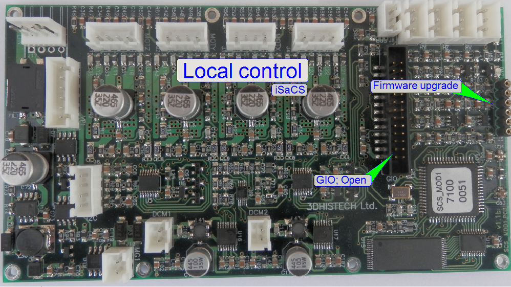 The shown
electronics board is used to control
The shown
electronics board is used to control
·
Transporter
·
Stain applicator
·
cover slipping
·
And
Differences are given in the
address of the board and connected units; the board itself is identical; the
firmware also.
Remark
Because the address is
different for each board, an interchange of the board between the named units
without address modifying is impossible!
·
To find the description
of connected units for the cable labels (Name), click the group link
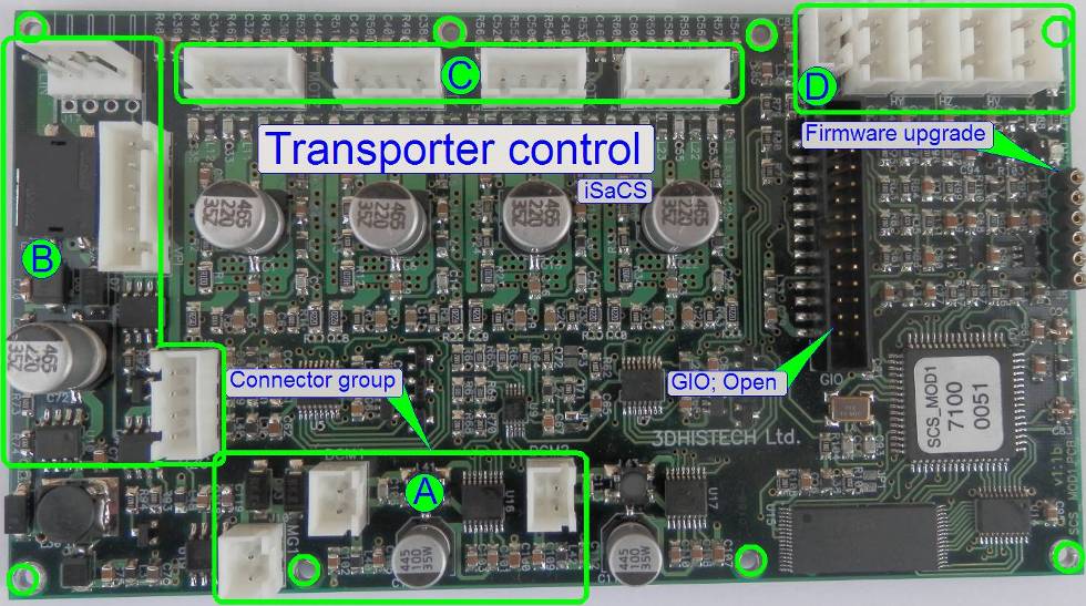
|
Connections of “Transporter control” |
||||
|
Name |
Type |
Group |
Source or Target |
Description |
|
MGMM-1 |
Solenoid 12V driven by 15V |
Slide mover fork |
Holds the slide |
|
|
LBMM-2 |
Local communication bus |
Main control
board |
Control of units |
|
|
SMMM-3 |
Step motor in Z-direction |
Transporter |
Move slide
along mathematical axes |
|
|
SMMM-2 |
Step motor in Y-direction |
|||
|
SMMM-1 |
Step motor in X-direction |
|||
|
OPMM-1 |
Home sensor X-direction |
Transporter |
Detect home
position for axis |
|
|
OPMM-2 |
Home sensor Y-direction |
|||
|
OPMM-3 |
Home sensor Z-direction |
|||
·
To find the description
of connected units for the cable labels (Name), click the group link
|
Connections of “Stain applicator” |
||||
|
Name |
Type |
Group |
Source or Target |
Description |
|
Open |
Not used |
|
|
|
|
LBPM-2 |
Local communication bus |
Main control
board |
Control of units |
|
|
SMPM-4 |
Step motor “Air pump” |
Applicator
head |
Move tip
acceptor along axes; Vacuum or
pressure for tip |
|
|
SMPM-3 |
Lift motor in Z-direction |
|||
|
SMPM-2 |
Step motor in Y-direction |
|||
|
SMPM-1 |
Tip mover in X-direction |
|||
|
OPPM-1 |
Pressure sensor |
Pipette
tip |
Vacuum; pressure |
|
|
USPM-1 |
Fluid level |
Reagent
vial |
Reagent quantity |
|
|
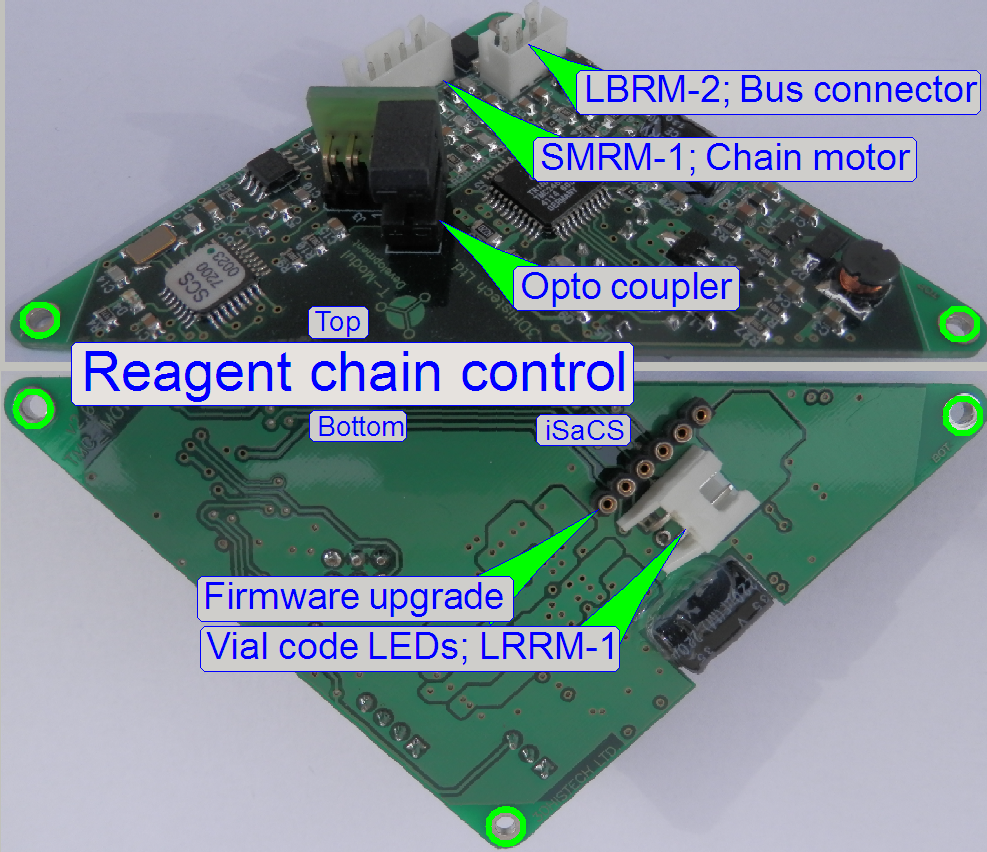
Connections of “Reagent chain” |
|||
|
Name |
Type |
Source or Target |
Description |
|
LBRM-2 |
Local communication bus |
Main control
board |
Control of units |
|
SMRM-1 |
Step motor |
Vial chain |
Move circularly
the vial chain |
|
LRRM-1 |
Illumination LEDs |
Reagent barcode |
Illumination |
·
To find the description
of connected units for the cable labels (Name), click the group link
|
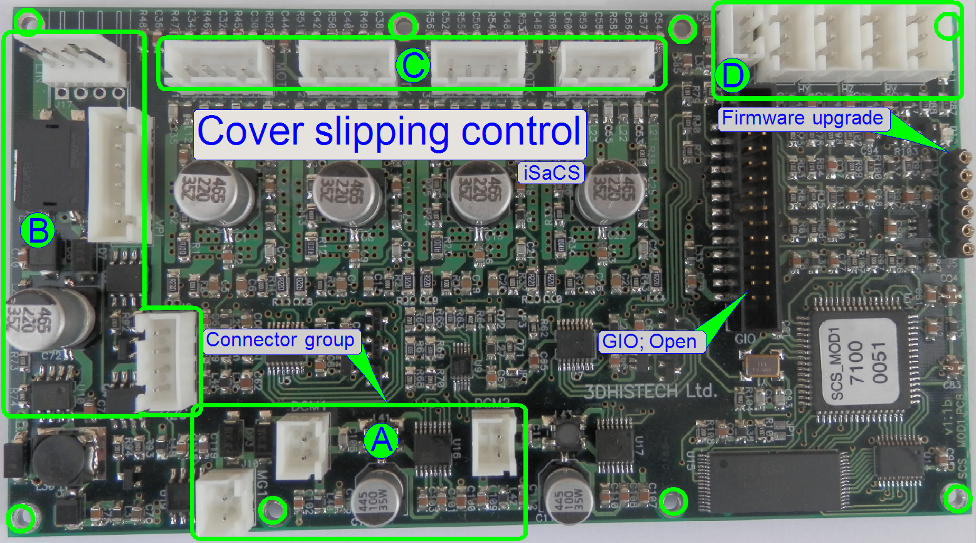
Connections
of “Cover slipping” |
||||
|
Name |
Type |
Group |
Source or Target |
Description |
|
Open |
Not
used |
|
|
|
|
LBCM-2 |
Local
communication bus |
Main control board |
Control of units |
|
|
VPCM-1 |
Pressure
sensor |
Sensor; pump; Valve |
|
|
|
SMCM-4 |
Step
motor “V” |
Applicator
head |
Move tip acceptor
along Z-axis; Vacuum or pressure for
tip |
|
|
SMCM-3 |
Lift
motor in Z-direction |
|||
|
Open |
-------- |
|||
|
SMCM-1 |
Step
motor “X” ?? |
|||
|
OPCM-1 |
Opto
sensor |
Pipette tip |
Vacuum; pressure |
|
|
USCM-1 |
Fluid
level |
Mounting medium |
Medium quantity |
|
·
To find the description
of connected units for the cable labels (Name), click the group link
|
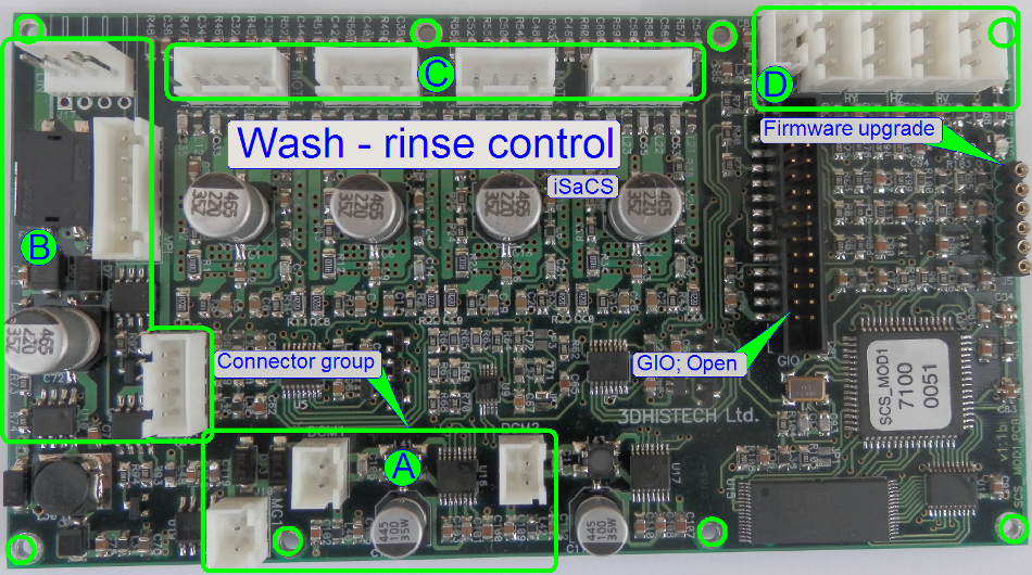
Connections
of “Wash-rinse” |
||||
|
Name |
Type |
Group |
Source or Target |
Description |
|
Open |
Not
used |
|
|
|
|
LBWM-2 |
Local communication bus |
Main control board |
Control of units |
|
|
SMWM-4 |
Step
motor “Slider” |
Wash-rinse chambers |
Move fluid nozzles |
|
|
SMWM-3 |
Pump
“WASTE” |
Pumps |
Move dedicated fluids |
|
|
SMWM-2 |
Pump
“Rinsing” |
|||
|
SMWM-1 |
Pump
“ |
|||
|
OPWM-4 |
Slider home sensor |
Wash-rinse |
Detect home position |
|