Control units;
iSaCS
For technicians
Main
control
Addresses of staining and cover slipping
|
Addresses SC units |
||
|
Unit |
Address |
Type |
|
Main control |
|
|
|
Transporter |
|
|
|
Stain applicator |
|
|
|
Reagent chain |
|
|
|
Cover slipping |
|
|
|
Wash rinse |
|
|
|
Legend: |
||
The entire staining and cover slipping part of the iSaCS is controlled
through a USB cable by the PC, different from the scanner part. The staining
and cover slipping part is divided into several control electronics, and
addresses are used to distinguish the data stream for the controllers.
The addresses are programmed into the unit, so each unit is unique in
the system. Several controllers are from the same construction.
Wire
labels; names
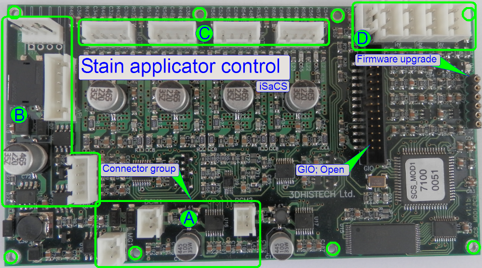
There are numerous connectors, so they are grouped to increase their
manageability.
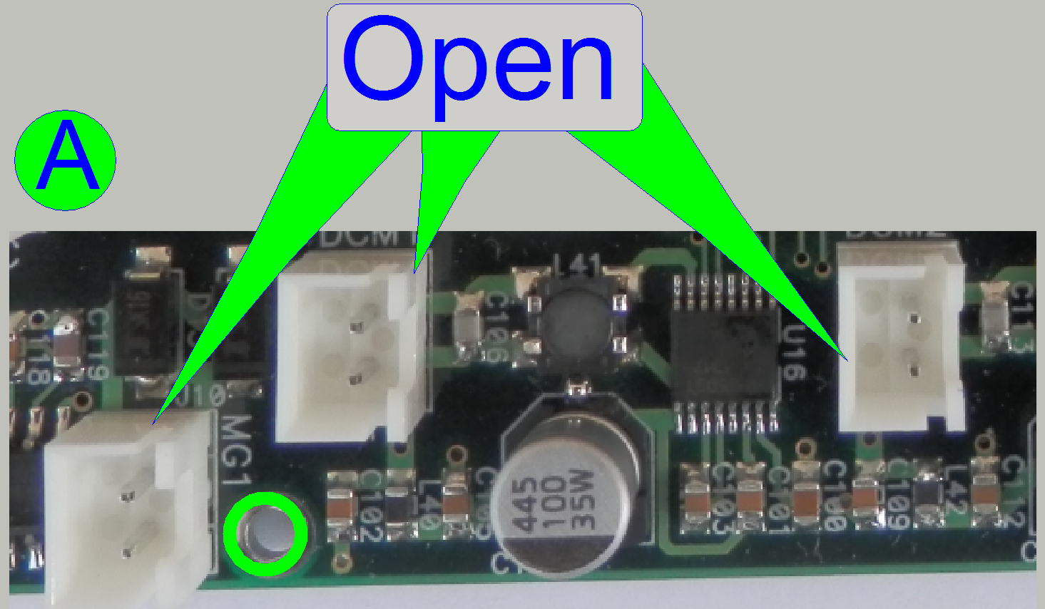
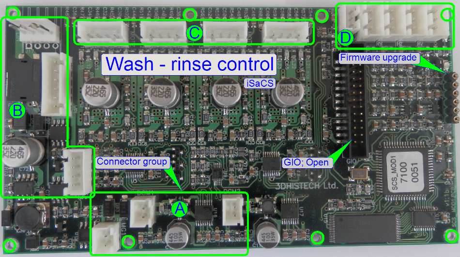
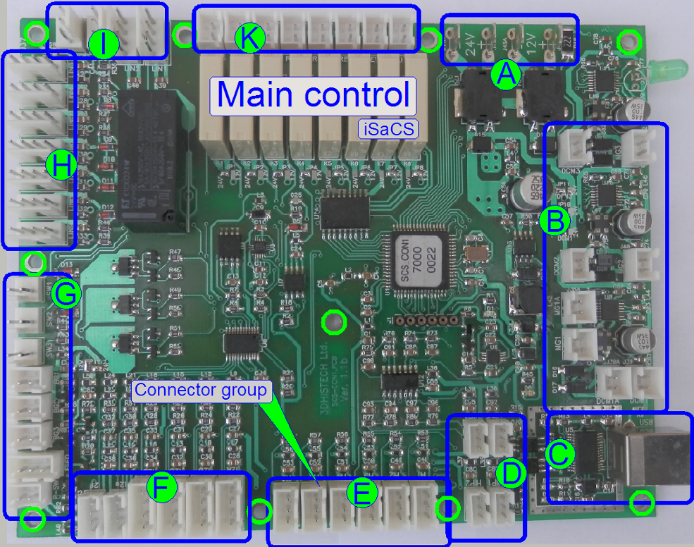 Groups of connections
· A
= Power supply
· B
= Housing
· C
= USB communication
· D
= Plug sensors
· E
= Container sensors
· F
= Optical sensors
· G
= Switches
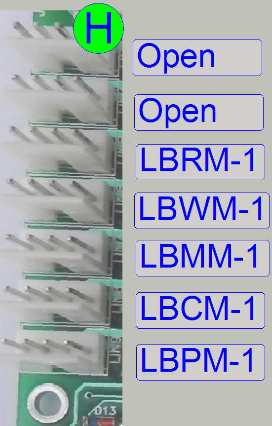
· H
= Bus connections
· I = Micro switches
· K
= Relay outputs
|
Connections of the
“Main control” board |
||||
|
Name |
Type |
Group |
Source or Target |
Description |
|
±12V |
Power |
Power tower |
Through connector “Power
Main electronics” |
|
|
±24V |
Power |
|||
|
ASHM-1 |
Container door |
Bottom right cover |
Locked “Off” / Released
“On” Solenoid latch locks the
lower right cover |
|
|
USBM-1 |
USB bus |
USB I/O board |
Software communication;
located below the left side service door |
|
|
HPTM-1 |
Pressure sensor |
Plug “Wash buffer” |
Through these container
sensors, the fluid level is recognized |
|
|
HPTM-2 |
Pressure sensor |
Plug “Distilled water” |
||
|
HPTM-3 |
Pressure sensor |
Plug “Hazardous waste” |
||
|
HPTM-4 |
Pressure sensor |
Plug “Non-hazardous waste” |
||
|
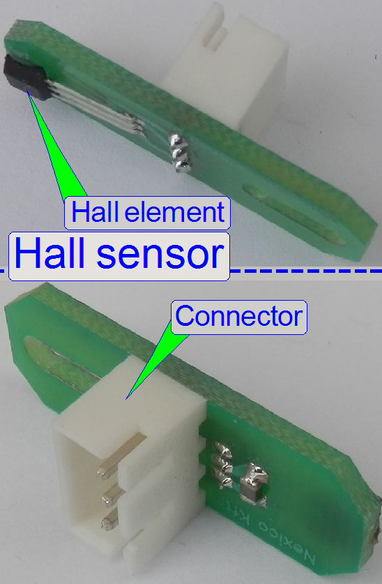
HATM-1 |
Hall sensor |
Position “Wash buffer” |
Container position
recognized, if the sensor shows active state |
|
|
HATM-2 |
Hall sensor |
Position “Distilled water” |
||
|
HATM-3 |
Hall sensor |
Position “Hazardous waste” |
||
|
HATM-4 |
Hall sensor |
Position “Non-hazardous
waste” |
||
|
IRCM-1 |
Optical sensor |
Pipette tip sensor |
IR sensor for staining;
for used pipette tip |
|
|
IRRM-1 |
Optical sensor |
Reagent changer |
IR sensor for vials |
|
|
IRFM-1 |
Pipette tip checker |
Cover slipping |
IR sensor for mounting
medium |
|
|
IRMM-1 |
Optical sensor |
Slide handling |
Slide present or absent |
|
|
ITFM-1 |
Slide sensor |
Slide mover |
IR sensor; present or
absent |
|
|
SIFM-1 |
Micro switch |
Slide rack; wash-rinse |
Rack inserted correctly |
|
|
SCFM-1 |
Micro switch |
Reagent tray |
Tray inserted correctly |
|
|
STHM-1 |
Tank switch |
|
|
|
|
LTDM-1 |
Illumination |
DF illumination for slide
image |
Front: “On” or “Off” |
|
|
LMDM-1 |
Illumination |
DF illumination for slide
image |
Rear: “On” or “Off” |
|
|
LLDM-1 |
Illumination |
For barcode in slide image |
“On” or “Off” |
|
|
LZHM-1 |
“On/Off” front |
Main switch for the entire
iSaCS |
Front of upper cover |
|
|
SZHM-1 |
“On/Off” front |
|||
|
LBRM-1 |
Vial chain |
Control board “Vial chain
control” |
Internal control bus |
|
|
LBWM-1 |
Wash-rinse |
Control board “Wash rinse” |
Internal control bus |
|
|
LBMM-1 |
Transporter |
Control board
“Transporter” |
Internal control bus |
|
|
LBCM-1 |
Cover slipping |
Control board “Cover
slipping” |
Internal control bus |
|
|
LBPM-1 |
Reagent applicator |
Control board “Reagent
applicator” |
Internal control bus |
|
|
SRHM-1 |
Reagent switch |
|
|
|
|
SSHM-1 |
Slide switch |
|
|
|
|
FSHM-1 |
Float sensor |
Overflow basin |
Fluid level sensing in
overflow basin |
|
|
VWFM-1 |
Valve “Waste” |
State of the valve paths |
Path open or closed |
|
|
VFFM-1 |
Valve “Flush” |
|||
|
VAFM-1 |
Valve “Air” |
|||
|
COFM-1 |
Wipe Compressor |
Beside non-hazardous waste
container |
“On” or “Off” |
|
|
LTFM-1 |
Transp. LED line |
Internal units
illumination; |
“On” or “Off” |
|
|
LMFM-1 |
Top LED line |
|||
|
LLHM-1 |
Logo illumination |
Upper left cover front |
Switch Logo on or off |
|
|
ARHM-1 |
Upper cover right |
Solenoid latch locks the
covers during processes in progress |
Upper covers always
released at same time |
|
|
ALHM-1 |
Upper cover left |
|||
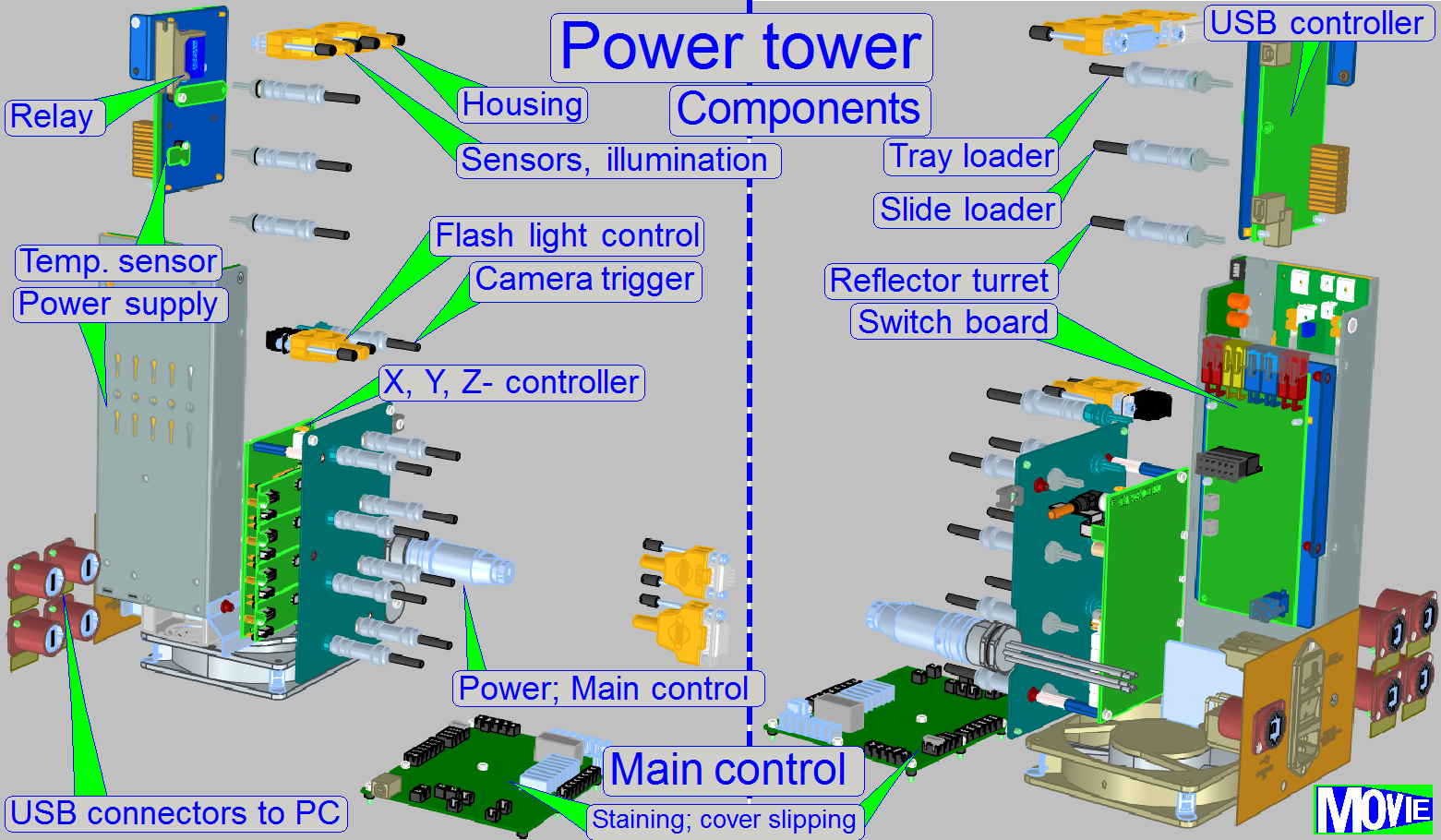
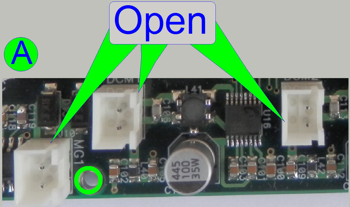
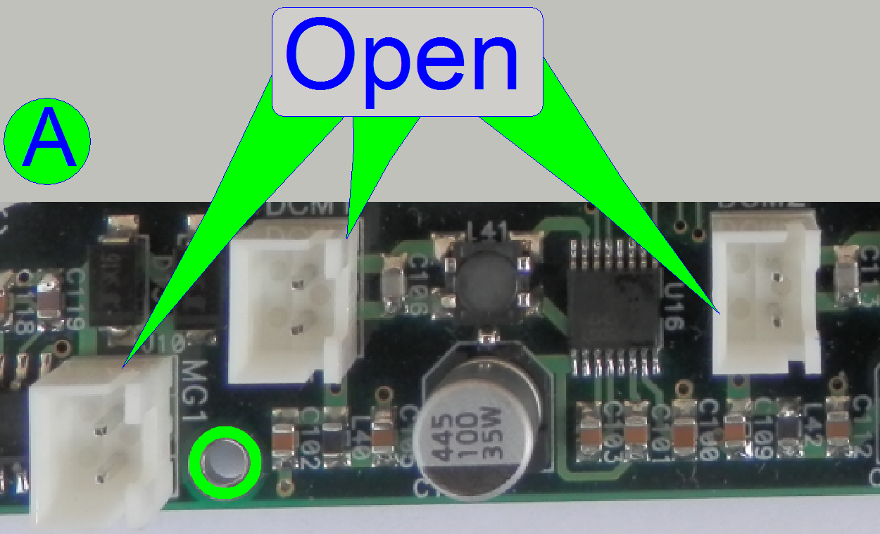
Power supply
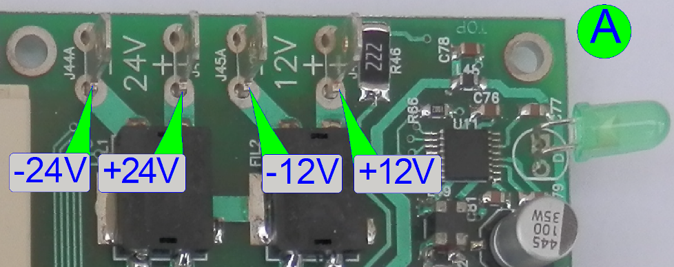 The power supply
of the main control board is realized by the ±24V and the ±12V line; supplied
directly from the power tower’s power supply TDK Lambda through the connector
“Power, Main electronics”.
The power supply
of the main control board is realized by the ±24V and the ±12V line; supplied
directly from the power tower’s power supply TDK Lambda through the connector
“Power, Main electronics”.
Housing
Open
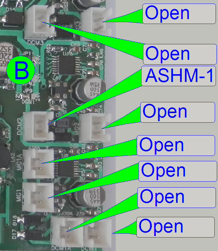
This connector is left unconnected; it may be used in later versions.
ASHM-1
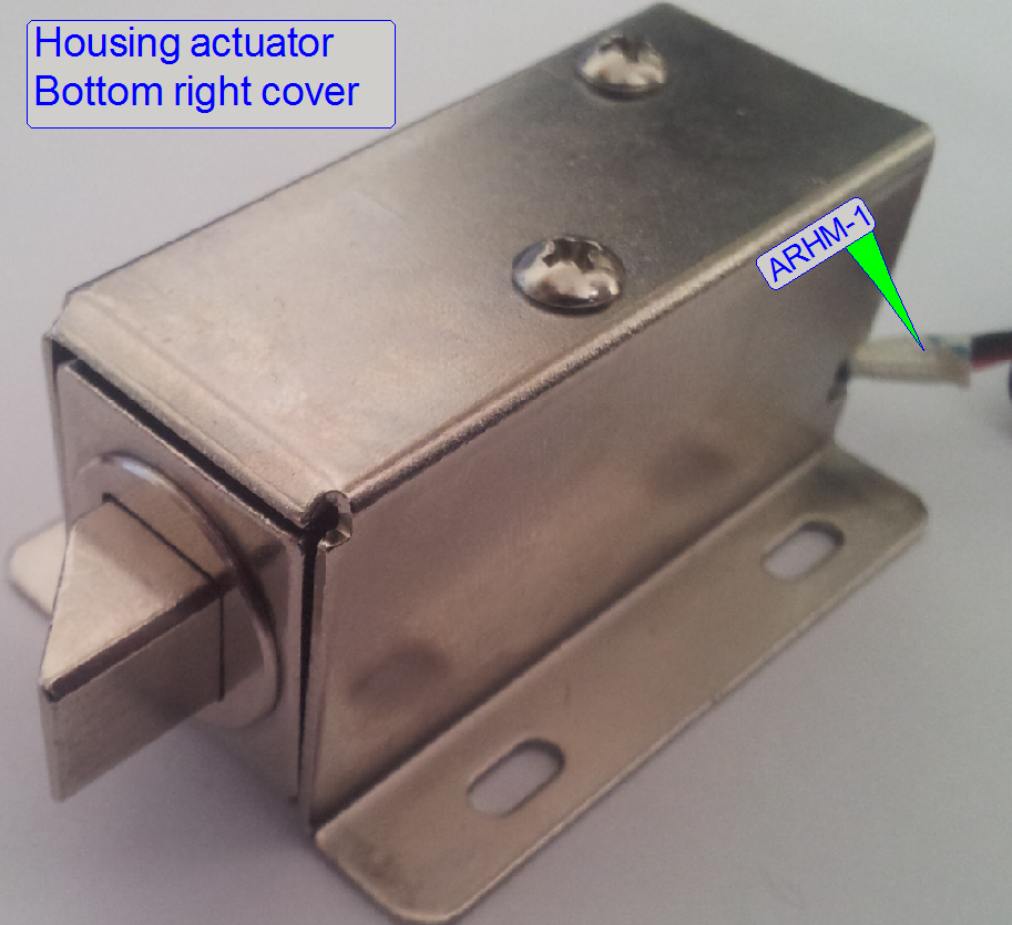 The bottom right
cover door is locked or unlocked by controlling this output.
The bottom right
cover door is locked or unlocked by controlling this output.
USB2.0
communication
By the use of an internal USB2.0 cable, the Main control unit is
connected to the computer’s USB2.0 port via the “USB connector board”
Plug
sensors
The pressure controlled sensors of each plug is connected here; plug the
sensor connector into the right position; see also: “Containers”.
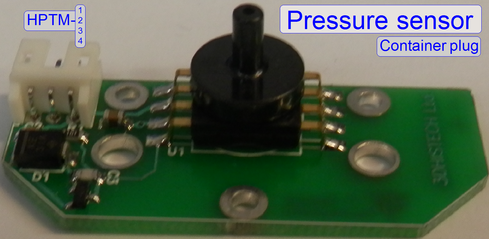
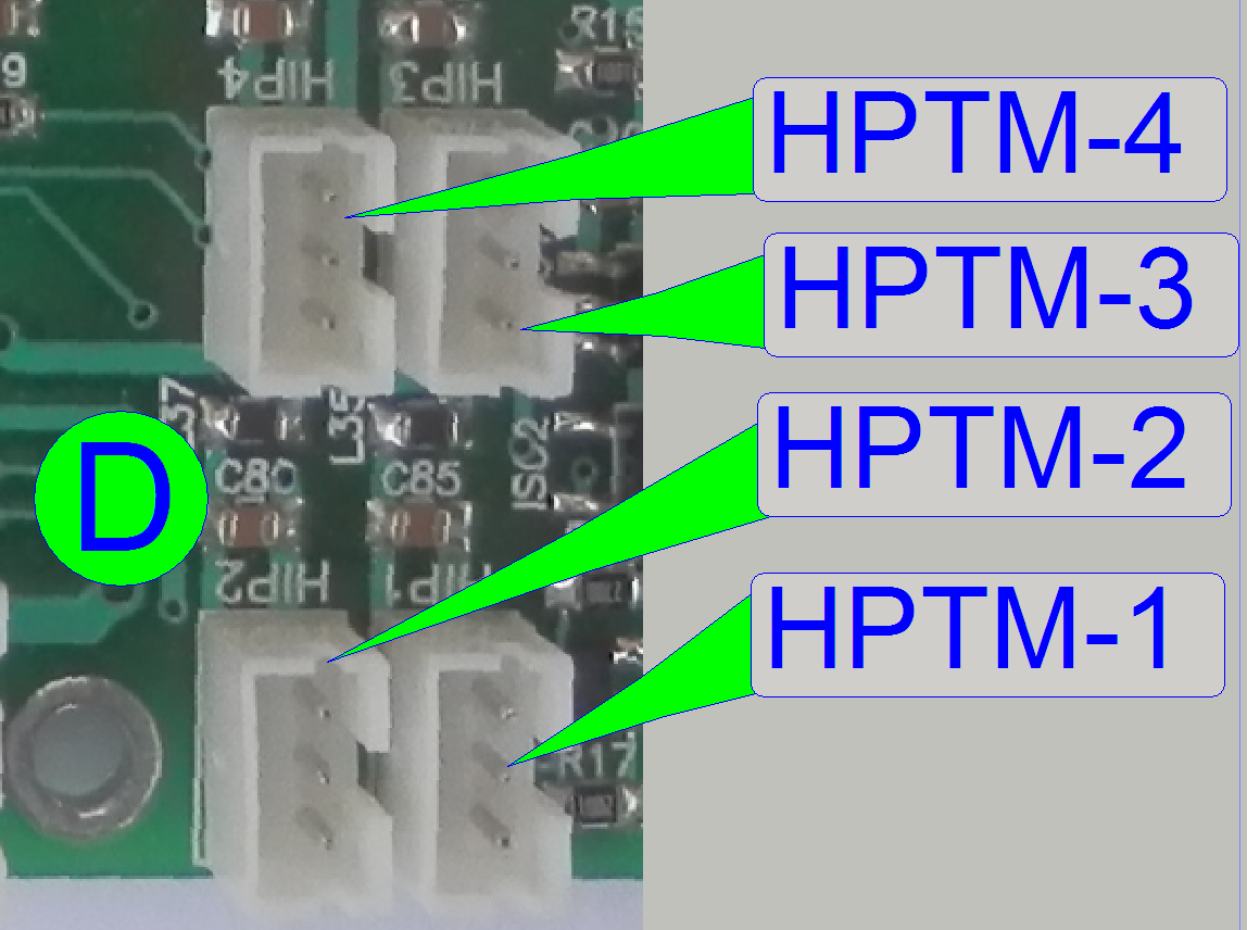 HPTM-1
Wash buffer
HPTM-2
Distilled water
HPTM-3
Hazardous waste
HPTM-4
Non-hazardous waste
Container
position
The sensors are used to distinguish the containers and to check their
correct position; see also: “Containers”
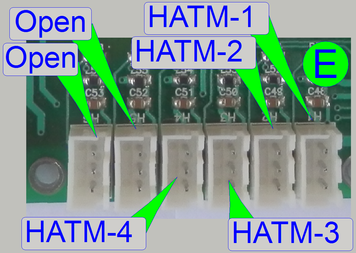 HATM-1
Wash buffer
HATM-2
Distilled water
HATM-3
Hazardous waste
HATM-4
Non-hazardous waste
Optical
sensor
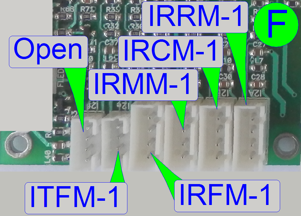
IRRM-1
IRCM-1
IRMM-1
IRFM-1
Pipette tip checker; Cover slipping; tip holder
ITFM-1
IR sensor in the slide mover; Slide in the slide clamp or not
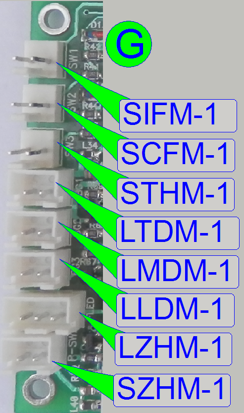
Units’
switches
Open
This connector is actually left unconnected; it may be used in later
versions.
SIFM-1
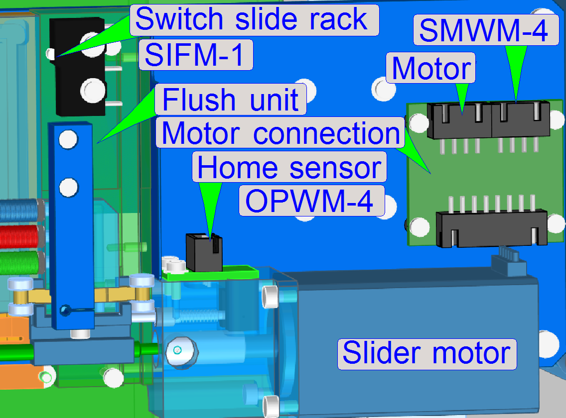 Connection to the
micro switch “Slide Rack Switch”; it signals the correct presence of the slide
rack.
Connection to the
micro switch “Slide Rack Switch”; it signals the correct presence of the slide
rack.
SCFM-1
Switch Reag. tray
STHM-1
Tank switch
LTDM-1; LMDM-1
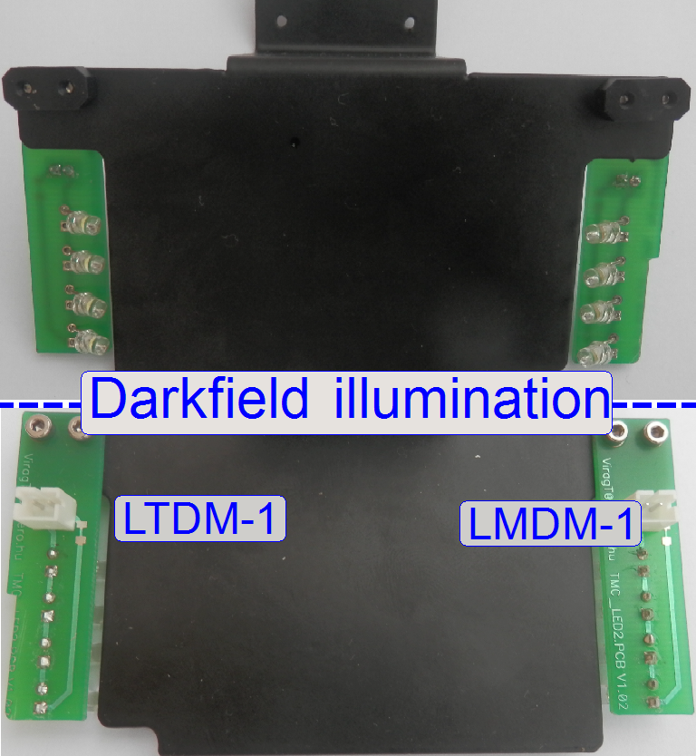 Darkfield slide
illumination to make the „Slide view“
Darkfield slide
illumination to make the „Slide view“
The LEDs are arranged in an angle of ~45° in relation to the slide
surface and illuminating so the slide from beneath.
· The both led rows
are always switched on or off together.
LLDM-1
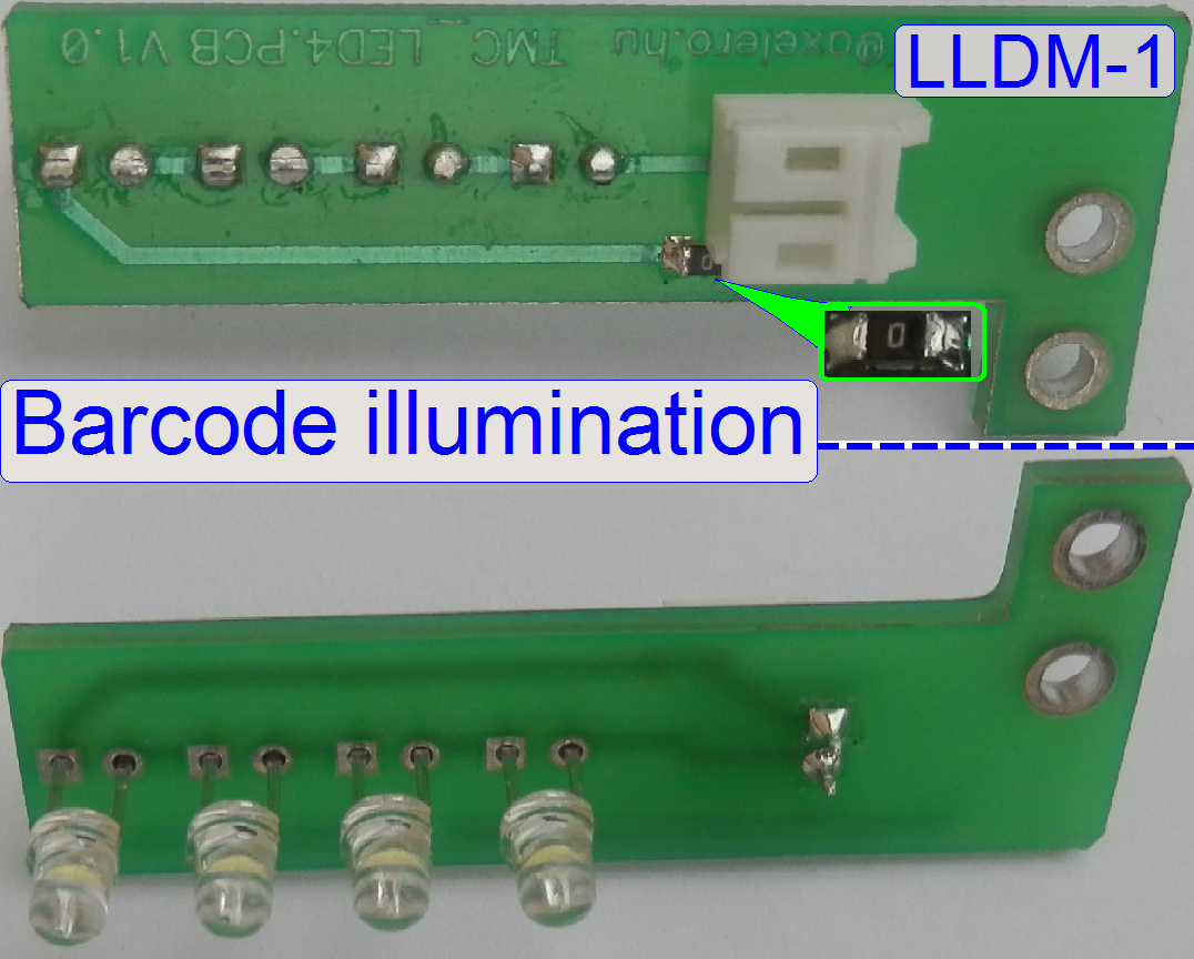
Barcode illumination LEDs for he slide during
“Slide view” capturing.
· Te LEDs are
illuminating only the barcode part of the slide
LZHM-1; SZHM-1
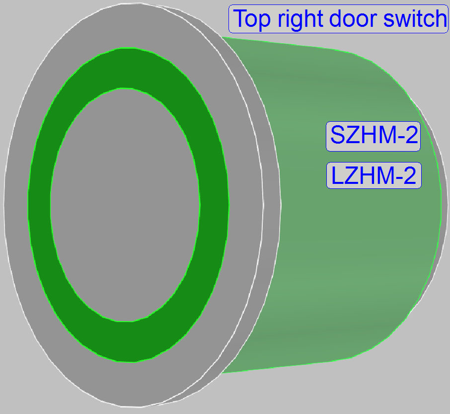 In front of upper
cover; by acting the cover switch, the software stops current processes and
allows the opening of the top covers.
In front of upper
cover; by acting the cover switch, the software stops current processes and
allows the opening of the top covers.
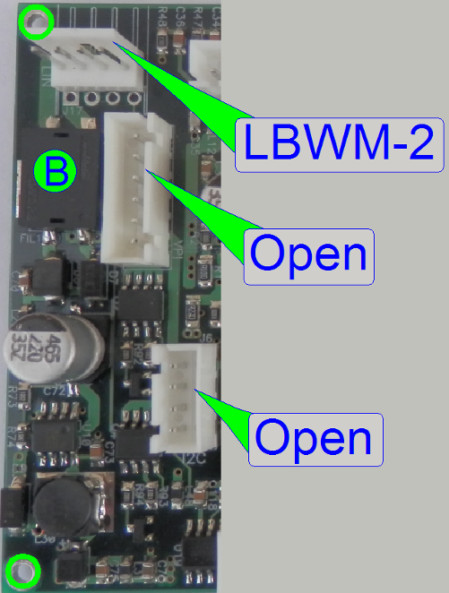
Bus
Connections
 The connector
group distributes the I2C bus to the local controllers inside the staining and
cover slipping unit.
The connector
group distributes the I2C bus to the local controllers inside the staining and
cover slipping unit.
Open
This connector is actually left unconnected; it may be used in later
versions.
LBRM-1
Control board “Vial chain control” Internal control bus
LBWM-1
Control board “Wash rinse” Internal control bus
LBMM-1
Control board “Transporter” Internal control bus
LBCM-1
Control board “Cover slipping” Internal control
bus
LBPM-1
“Control board “Reagent applicator Internal control bus
Micro
switches
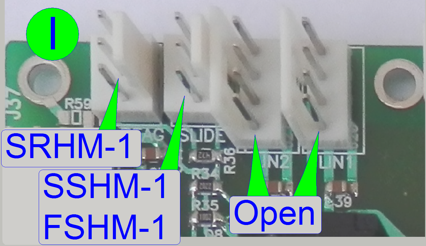
SRHM-1
Reagent switch
SSHM-1
Slide switch
FSHM-1
Float sensor
Relay
outputs
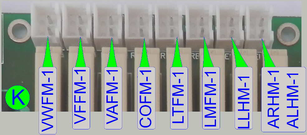 VWFM-1
Valve “WASTE” is controlled by this output.
VFFM-1
Valve “FLASH” is controlled by this output.
VAFM-1
Valve “AIR” is controlled by this output.
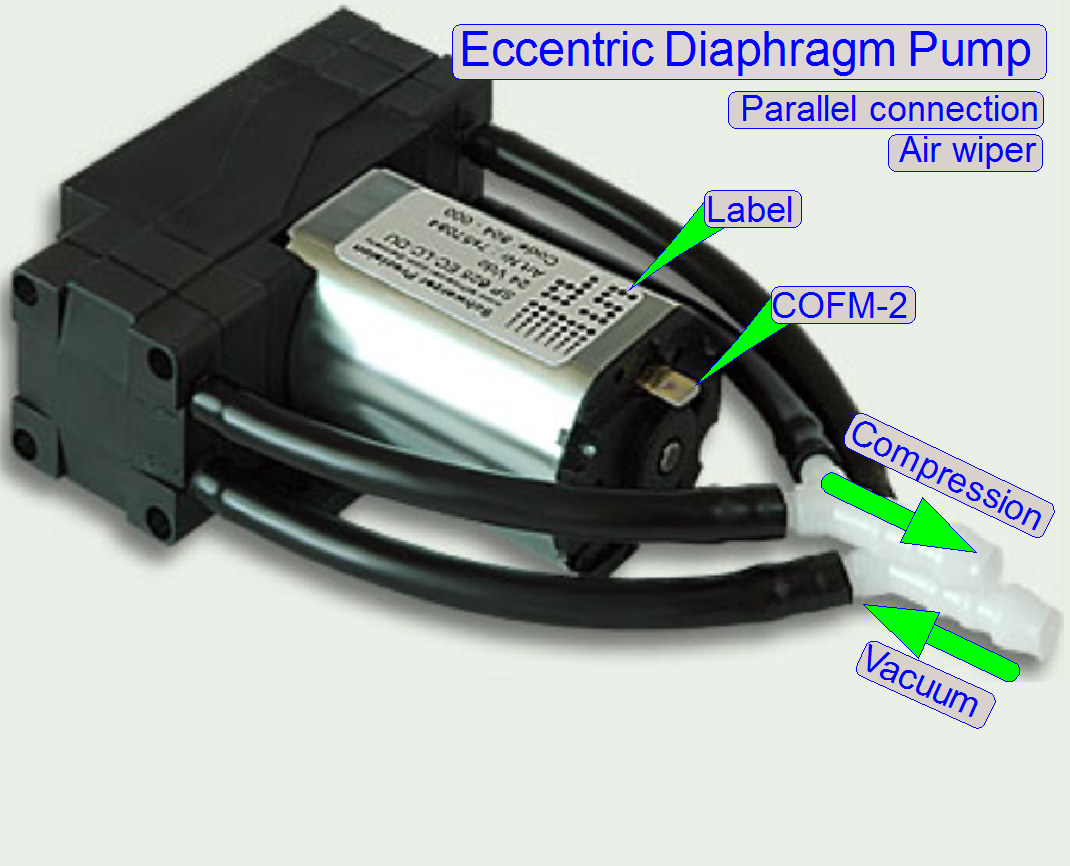 COFM-1
After the “Hirschmann” connector, the wire label is named as COFM-2
LTFM-1
LED is controlled by this output.
LMFM-1
LED is controlled by this output.
LLHM-1
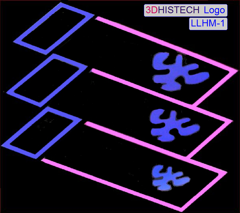 The 3DHISTECH
illuminated logo is controlled by this output.
The 3DHISTECH
illuminated logo is controlled by this output.
ARHM-1
 The top right
cover door is locked or unlocked by controlling this output.
The top right
cover door is locked or unlocked by controlling this output.
ALHM-1
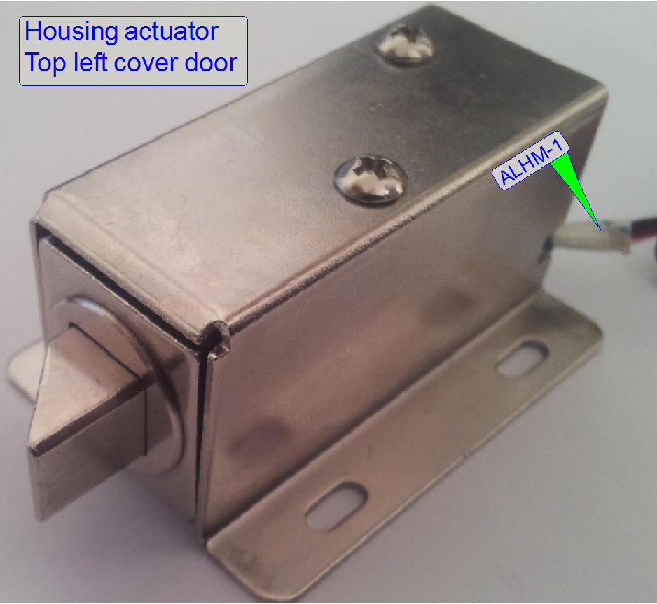 The top left cover
door is locked or unlocked by controlling this output.
The top left cover
door is locked or unlocked by controlling this output.
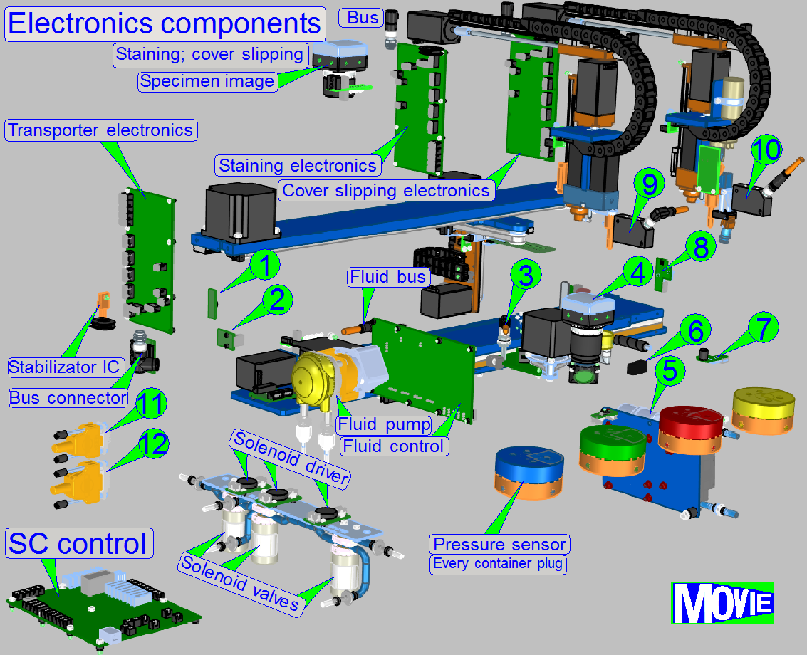
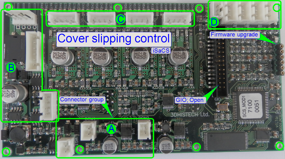
Local
control
The shown electronics board is used to control the
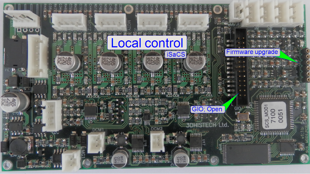
· transporter
· stain applicator
· cover slipping
· wash - rinse
The board exists 4x in the staining and cover slipping units;
differences are given in the address of the board and connected units; the
board itself is identical; the firmware also.
Remark
Because the address is different for each board, an interchange of the
board between the named units without address modifying is impossible!
Transporter
control
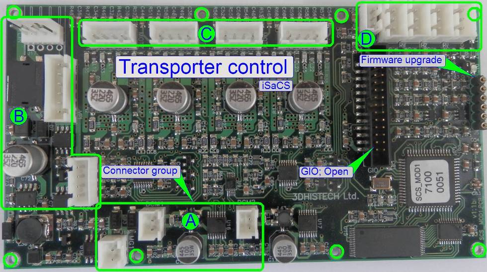
|
Connections of
“Transporter control” |
||||
|
Name |
Type |
Group |
Source or Target |
Description |
|
MGMM-1 |
Solenoid 15V; |
Slide fork |
Holds the slide |
|
|
LBMM-2 |
Local communication bus |
Main control board |
Control of units |
|
|
SMMM-3 |
Step motor in Z-direction |
Transporter |
Move slide along
mathematical axes |
|
|
SMMM-2 |
Step motor in Y-direction |
|||
|
SMMM-1 |
Step motor in X-direction |
|||
|
OPMM-1 |
Home sensor X-direction |
Transporter |
Detect home position for axis |
|
|
OPMM-2 |
Home sensor Y-direction |
|||
|
OPMM-3 |
Home sensor Z-direction |
|||
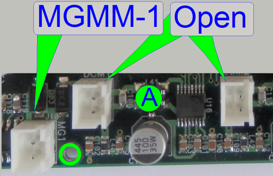
Open
This connector is actually left unconnected; it may be used in later
versions.
MGMM-1
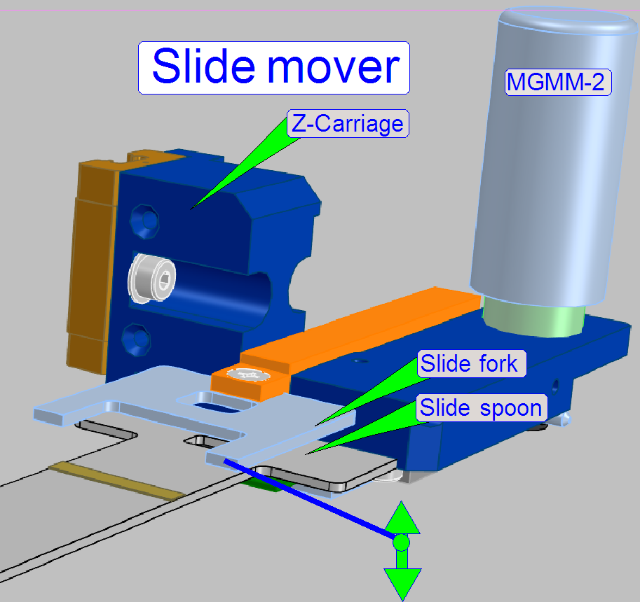 Via a voltage stabilization IC of 15V the
slide fork of the slide mover is controlled.
Via a voltage stabilization IC of 15V the
slide fork of the slide mover is controlled.
LBMM-1; 2
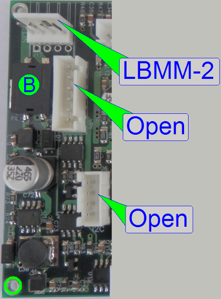
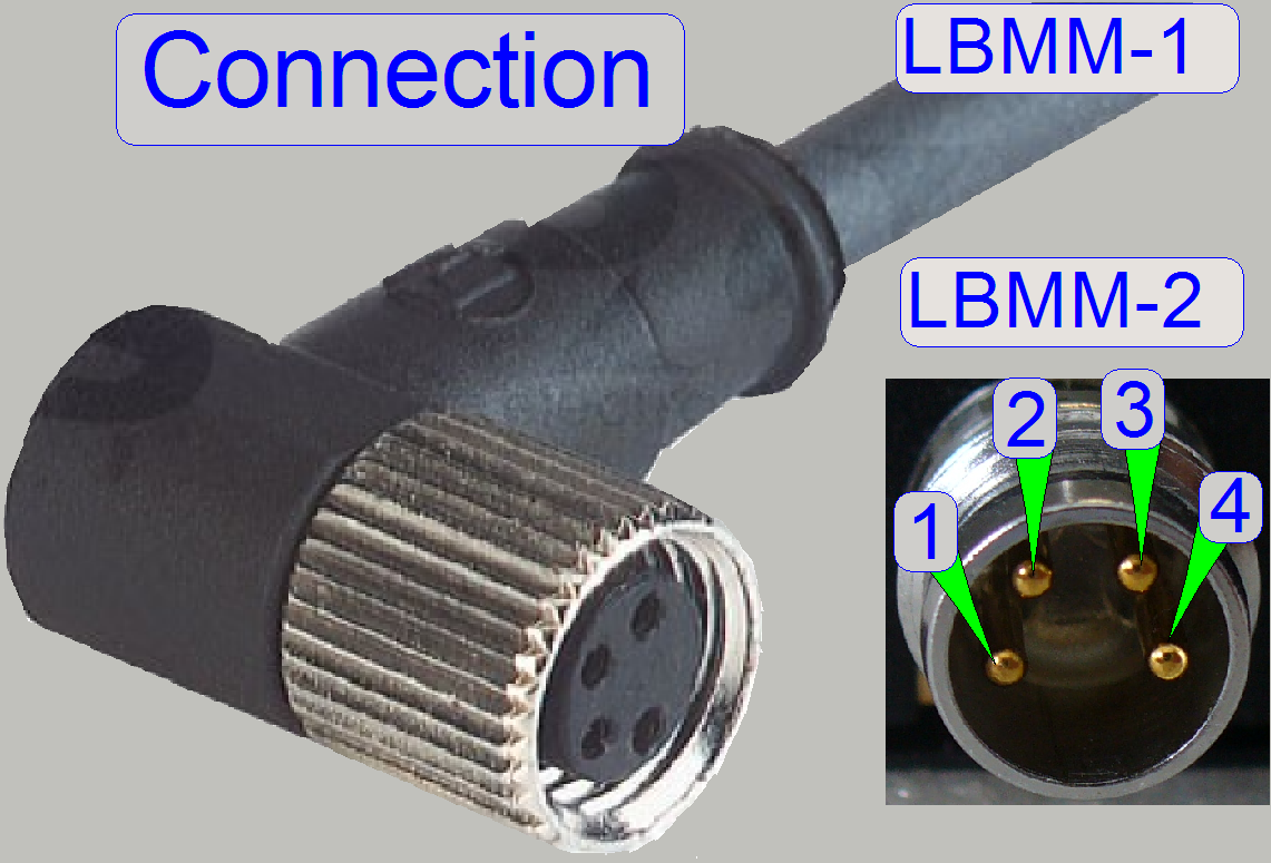
Local communication bus
Open
This connector is actually left unconnected; it may be used in later
versions.
SMMM-3
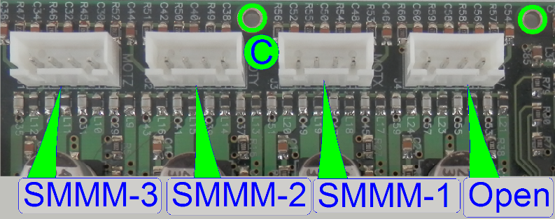 SMMM-2
SMMM-1
Open
This connector is actually left unconnected; it may be used in later
versions.
OPMM-3
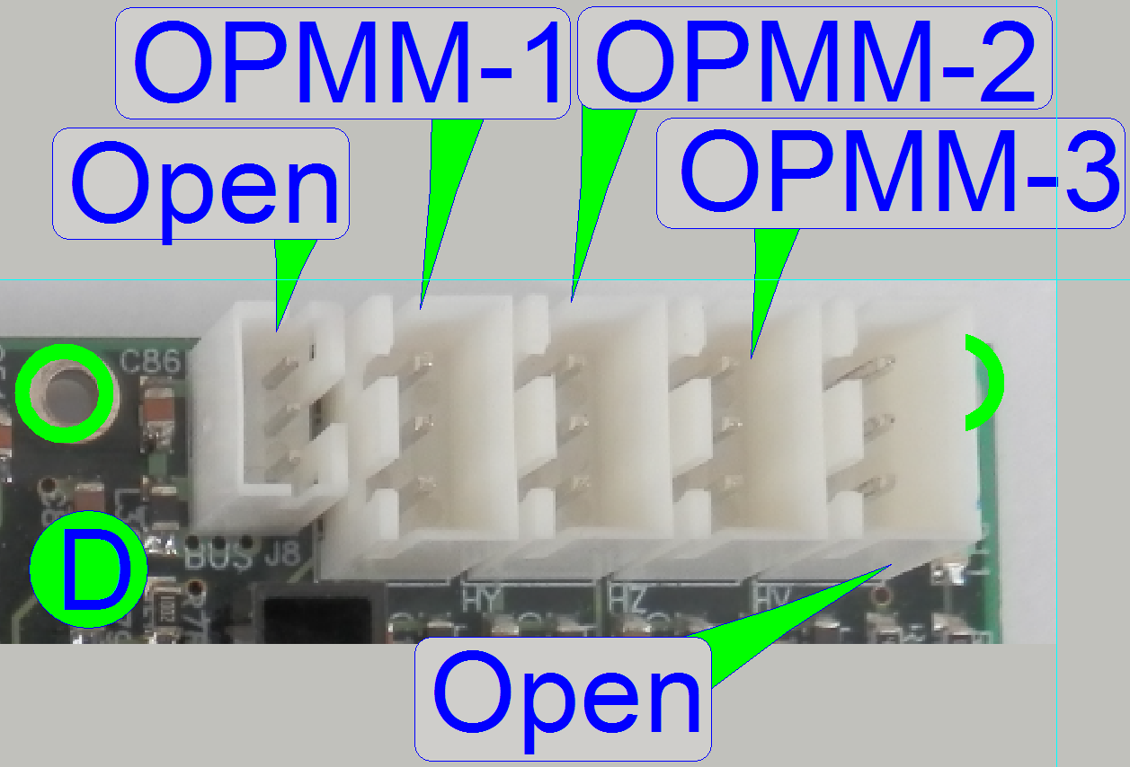 OPMM-2
OPMM-1
Open
This connector is actually left unconnected; it may be used in later
versions.
|
Connections of “Stain
applicator” |
||||
|
Name |
Type |
Group |
Source or Target |
Description |
|
Open |
Not used |
|
|
|
|
LBPM-2 |
Local communication bus |
Main control board |
Control of units |
|
|
SMPM-4 |
Step motor “Air pump” |
Applicator head |
Move tip acceptor along axes; Vacuum or pressure for tip |
|
|
SMPM-3 |
Lift motor in Z-direction |
|||
|
SMPM-2 |
Step motor in Y-direction |
|||
|
SMPM-1 |
Tip mover in X-direction |
|||
|
OPPM-1 |
Pressure sensor |
Pipette tip |
Vacuum; pressure |
|
|
USPM-1 |
Fluid level |
Reagent vial |
Reagent quantity |
|
 Open
Open
This connector is actually left unconnected; it may be used in later
versions.
Group
“B”
LBPM-2
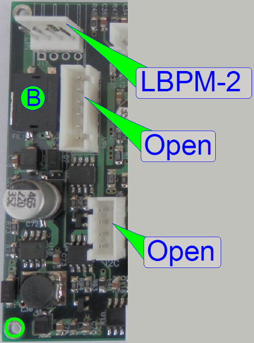
Open
This connector is actually left unconnected; it may be used in later
versions.
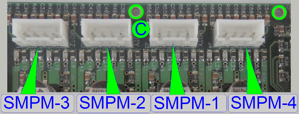
SMPM-1
SMPM-2
SMPM-3
SMPM-4
USPM-1
OPPM-1; OPPM-1
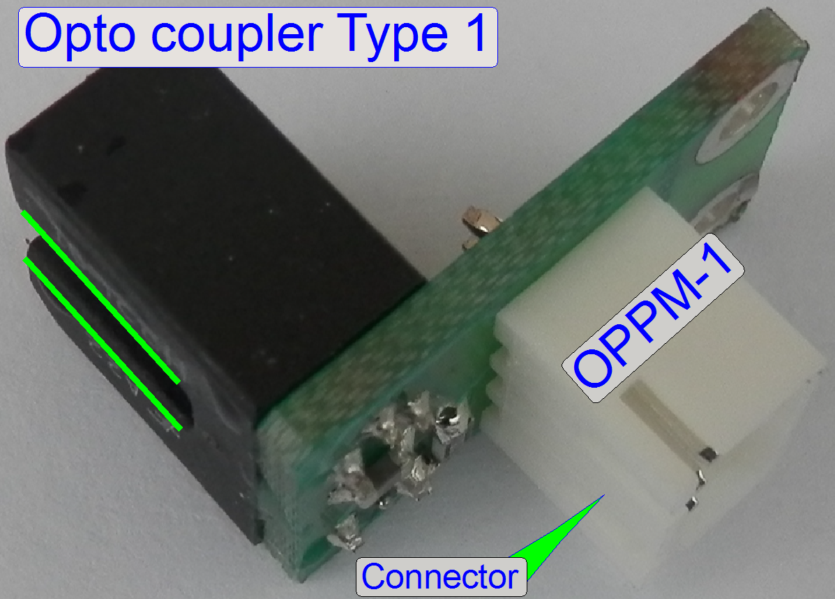
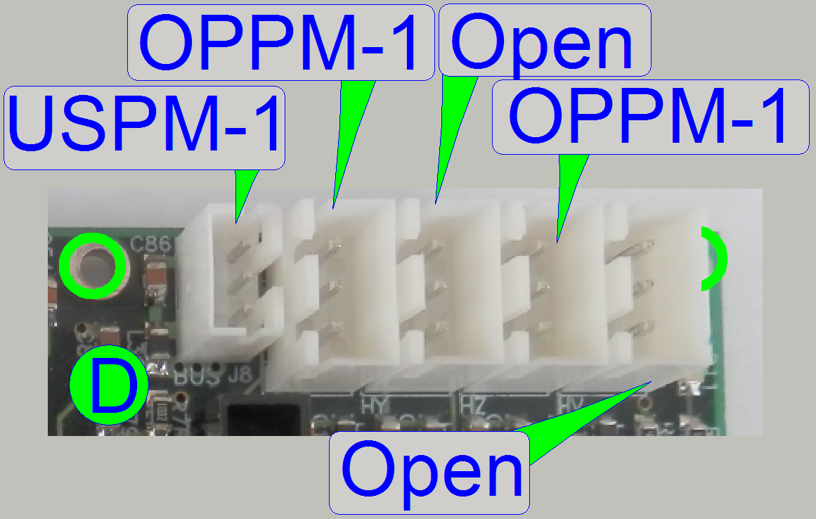 The wire has 2
connectors
The wire has 2
connectors
Open
This connector is actually left unconnected; it may be used in later
versions.
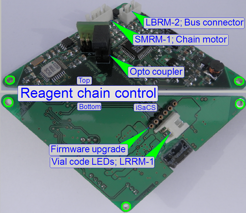
|
Connections of “Reagent
chain” |
||||
|
Name |
Type |
Source or Target |
Description |
|
|
LBRM-2 |
Local communication bus |
Main control board |
Control of units |
|
|
SMRM-1 |
Step motor |
Vial
chain |
Move circularly the vial chain |
|
|
LRRM-1 |
Illumination LEDs |
Reagent barcode |
Illumination |
|
Vial
chain’s position sensor
Through the “Opto coupler” mounted on the PCB a disc half is rotated and
this is mounted onto the Maltese cross’ disc. With this solution the Home position
can be adjusted, so the vial chain link can be stopped in the correct vial
position for filling the pipette tip.
|
Connections of “Cover slipping” |
||||
|
Name |
Type |
Group |
Source or Target |
Description |
|
Open |
Not used |
|
|
|
|
LBCM-2 |
Local communication bus |
Main control board |
Control of units |
|
|
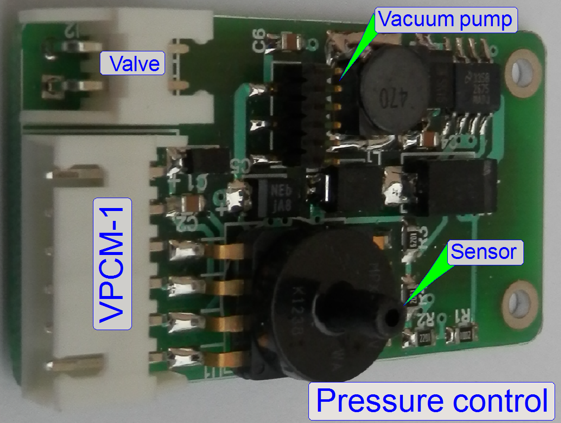
VPCM-1 |
Pressure sensor |
Sensor; pump; Valve |
Control components |
|
|
SMCM-4 |
Step motor “V” |
Applicator
head |
Move tip acceptor
along Z-axis; Vacuum or pressure for
tip |
|
|
SMCM-3 |
Lift motor in Z-direction |
|||
|
Open |
-------- |
|||
|
SMCM-1 |
Step motor “X” ?????????? |
|||
|
OPCM-1 |
Opto sensor |
Pipette
tip |
Vacuum; pressure |
|
|
USCM-1 |
Fluid level |
Mounting
medium |
Medium quantity |
|
Open
This connector is actually left unconnected; it may be used in later
versions.
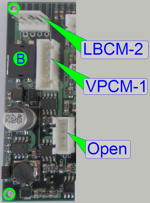
LBCM-2
VPCM-1
Open
This connector is actually left unconnected; it may be used in later
versions.
Group
“C”
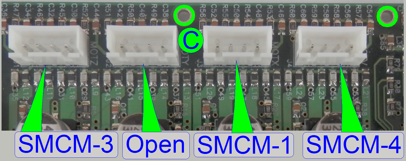 SMCM-1
SMCM-3
SMCM-4
Open
This connector is actually left unconnected; it may be used in later
versions.
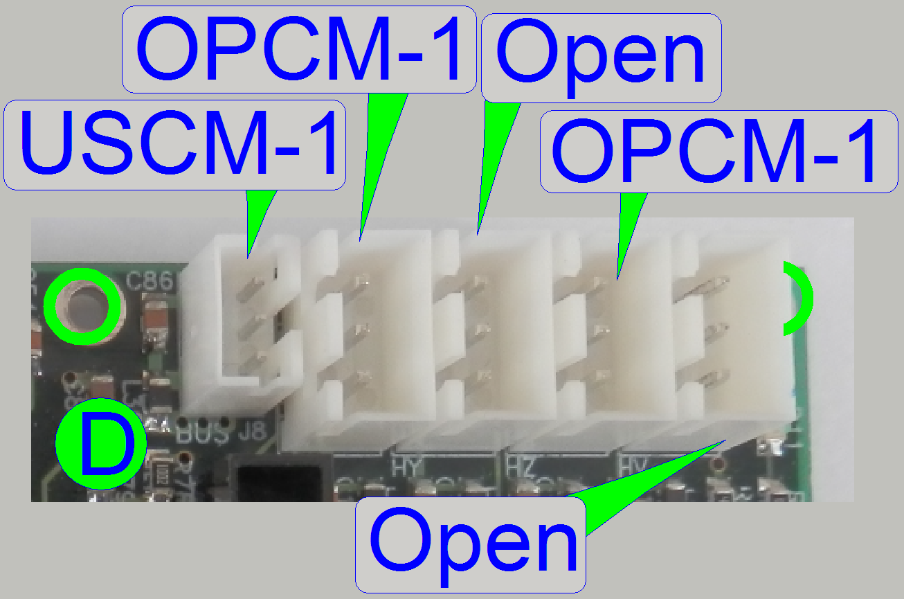
USCM-1
OPCM-1; OPCM-1
The wire end has 2 connectors
Open
This connector is actually left unconnected; it may be used in later
versions.
|
Connections of “Wash-rinse” |
||||
|
Name |
Type |
Group |
Source or Target |
Description |
|
Open |
Not used |
|
|
|
|
LBWM-2 |
Local communication
bus |
Main control board |
Control of units |
|
|
SMWM-4 |
Step motor “Slider” |
Wash-rinse chambers |
Move fluid nozzles |
|
|
SMWM-3 |
Pump “WASTE” |
Pumps |
Move dedicated
fluids |
|
|
SMWM-2 |
Pump “Rinsing” |
|||
|
SMWM-1 |
Pump “ |
|||
|
OPWM-4 |
Slider home sensor |
Wash-rinse |
Detect home position |
|
Open
This connector is actually left unconnected; it may be used in later
versions.
LBWM-2
Open
This connector is actually left unconnected; it may be used in later
versions.
SMWM-1
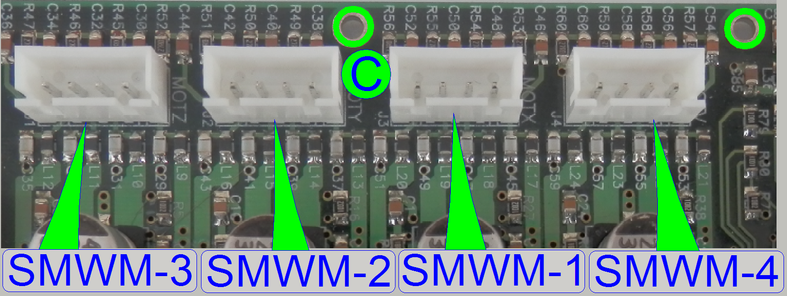 SMWM-2
SMWM-3
SMWM-4
See “Motor connection” board on the right
Open
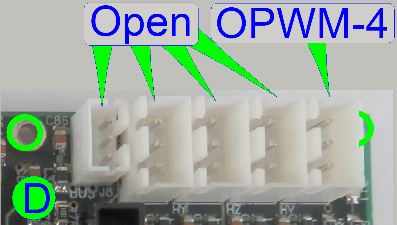 This connector is
actually left unconnected; it may be used in later versions.
This connector is
actually left unconnected; it may be used in later versions.
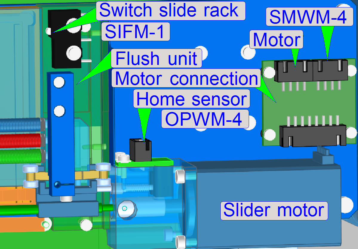
OPWM-4
Home sensor of the slider in the wash – rinse unit