Wash and rinse unit; iSaCS
For
technicians and partly for sales managers
 The
following chapter handles principles, tasks and components of the fluid control
during the washing and rinsing procedure of the 3DHISTECH iSaCS.
The
following chapter handles principles, tasks and components of the fluid control
during the washing and rinsing procedure of the 3DHISTECH iSaCS.
If the sample received the staining fluid during the
staining procedure, the incubation will be done in the chamber of its origin
place.
If the incubation time of the stain is over, the
specimen is moved to a free wash and rinse chamber.
Contents
Tasks
After finishing the incubation of staining, the
staining reagent has to be removed from the sample to stop the staining
process.
This task is done with the wash and rinse unit.
Before the wash - rinse procedure starts, the slide
with specimen is moved by the transporter from its origin place into a free
WR-chamber.
The washing fluid is based on distilled water and
contains chemicals to fix the properties of the stain.
When the washing procedure is finished, the waste
washing fluid is moved into a "waste” container (C3 or C4).
The rinsing of the tissue is done with distilled water
(C2); the waste fluid is moved into the appropriate "waste" container
(C3 or C4).
Thereafter, the slide is moved from the “Wash-Rinse”
chamber, to the “Air wiper” bay.
Finally, the fluid, remained on the specimen (slide
surface) will be blown off the sample surface by the “Air wiper”; so, the
sample surface will be dry. The slide is moved to its original place and waits
there for cover slipping or the staining procedure can be repeated with another
stain.
Hazardous and non-hazardous waste
In all cases, the selected fluid path depends on the
stain, used during the staining procedure.
If the stain to be removed is poisonous and / or
caustic, the waste washing and also the rinsing fluid is always collected in
the "Hazardous waste" container.
If the stain to be removed is nonpoisonous and no
caustic, the waste washing and rinsing fluid is always collected in the
"Non-hazardous waste" container.
Washing as well as rinsing fluid itself is not
declared as caustic or poisonous,
therefore these fluids are always collected in the "Non-hazardous
waste" container (during software start).
There are some situations, where the kind of fluid can
not be decided e.g. in the overflow system. In such cases, the fluid has to be
disposed always as "Hazardous waste".
Wash
buffer
 The wash buffer is based on distilled water and contains
salts and additional chemicals.
The wash buffer is based on distilled water and contains
salts and additional chemicals.
The used chemicals are mainly independent of the stain
type.
- Differences will be equalized by the incubation time of the washing
fluid.
For
TBS pH 7.4 dilution required ingredients
Tris base 120.825g
NaCl 75g
HCLcc ~38.75 ml
Distilled
water: add to the shown ingredients
distilled water until the capacity of 1000ml is reached.
o A 5l
wash buffer needs of course 5x quantities.
Information about main components and recipes of
washing fluids can be found in …………...
- Washing fluid
itself is declared as non-hazardous!
Distilled
rinsing water
The rinsing water is distilled water. Fill single
distilled water into the container.
· 40ml Tween-20 detergent
fluid is required for 1000ml of rinsing water.
- Rinsing fluid
itself is declared as non-hazardous!
Non-hazardous
waste
The fluid, removed as a result of the washing or
rinsing procedure after a non-hazardous reagent (stain) was used is stored
here.
- The container
content may be discharged as domestic waste water.
Hazardous
waste


The fluid, removed as a result of the washing or
rinsing procedure after a hazardous reagent (stain) was used is stored here.
- Hazardous waste has to be disposed into appropriate collecting
containers.
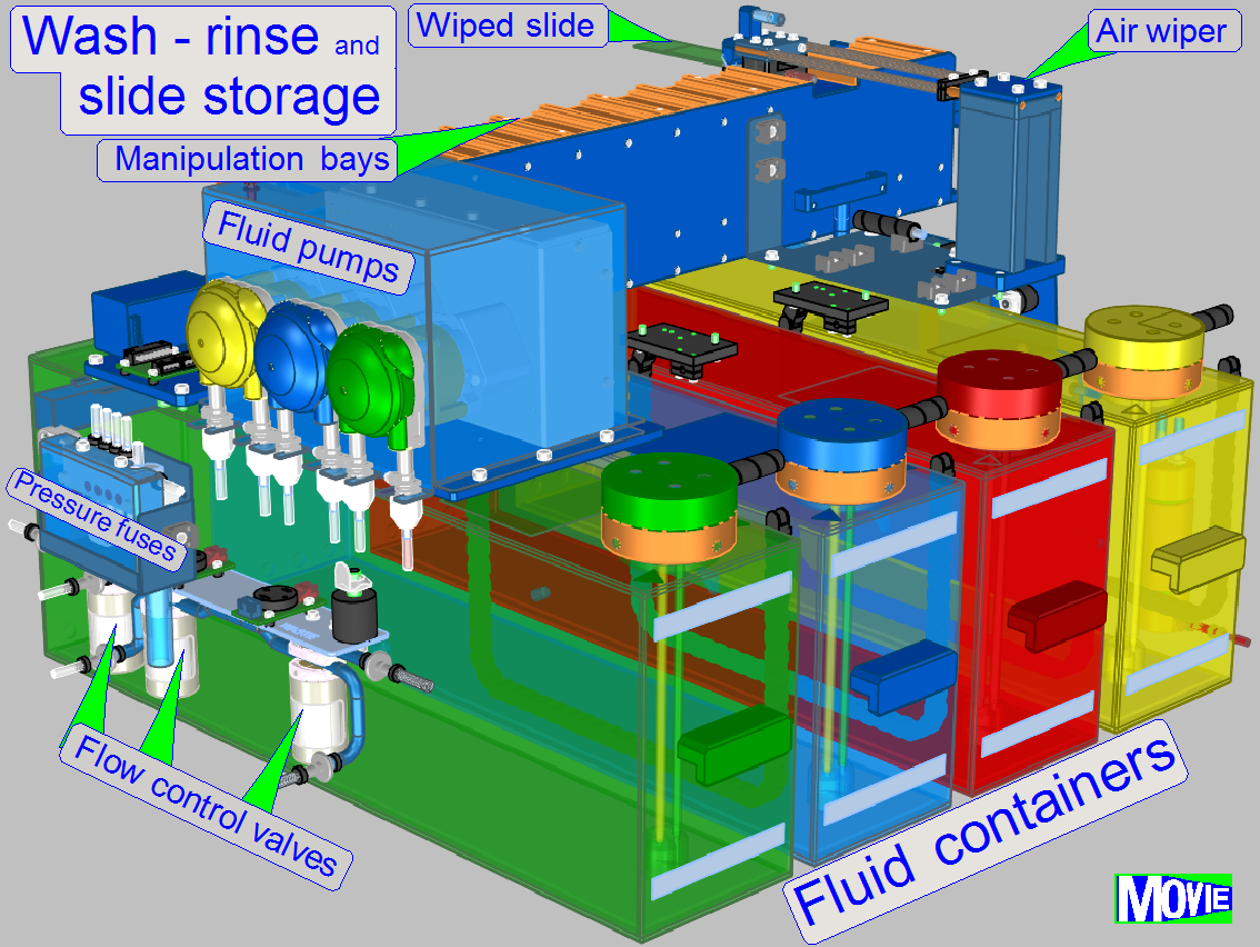
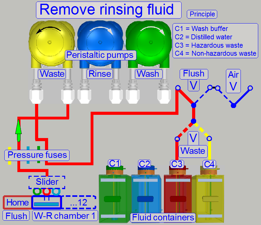
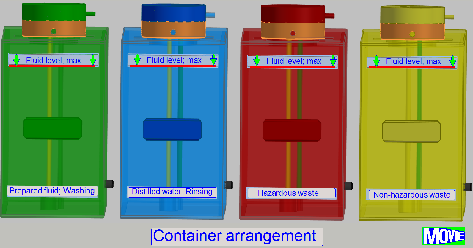 The
containers are arranged in the iSaCS as shown.
The
containers are arranged in the iSaCS as shown.
· The
sequential arrangement of the containers and so the fluid is important.
· Each
container may contain 5l of the appropriate fluid; filled until the lower edge
of the “Fluid max. label”.
·
Fill the container (
·
A minimum of 300ml fluid content in the
container is required; the system can not use fluid below this level for
washing or rinsing procedures
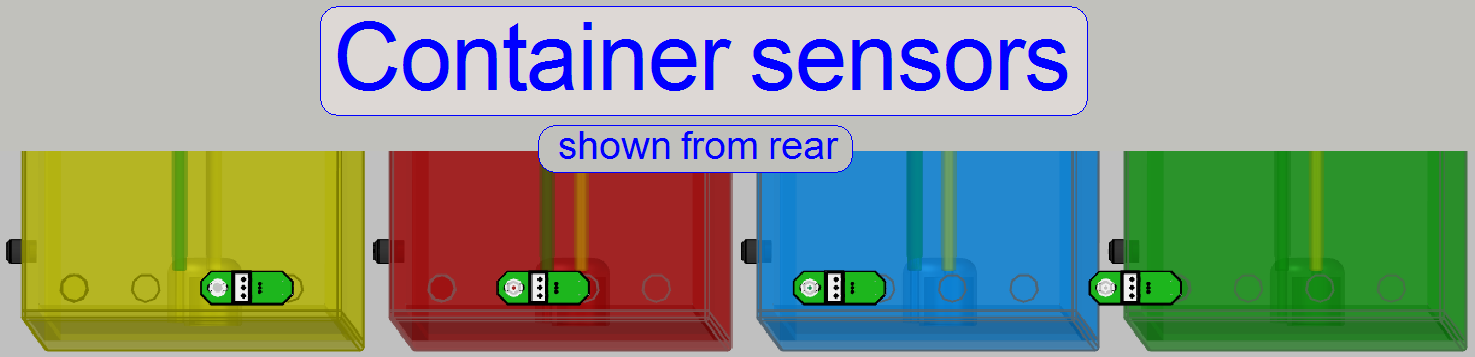
· The
states Container “empty”, “full” and “fluid present” are detected by a pressure
sensor in the plug.
· The
position of the containers is recognized by Hall sensors on the rear.
· The
user fills the containers for the wash and rinse process manually with the
appropriate fluid.
· The
content of the waste containers is disposed manually to appropriate collecting
containers.
· Each
container has its own plug to move the fluid out of the container (
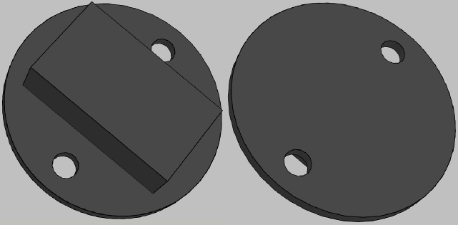
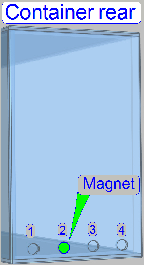 On the rear of the container, positions to hold a permanent
magnet are defined. By implementing (bonding) the permanent magnet at the
specified position, the container content (kind of fluid) and its position in
the arrangement is defined.
On the rear of the container, positions to hold a permanent
magnet are defined. By implementing (bonding) the permanent magnet at the
specified position, the container content (kind of fluid) and its position in
the arrangement is defined.
· This
way, each container has always the same position and an interchange of the
fluids is avoided!
Important
If the container was filled by mistake with incorrect
fluid, please clean and rinse the container and its plug with distilled water;
especially the container for the Rinse process!
By using sensors behind the containers, the position
and the fluid kind of the container are defined.
· If the
Hall sensor does not recognize a container, the container is missed (the
container position is empty) the container is not fully pushed to the rear (the
acting position of the sensor is not reached) or the container is in a wrong
place.
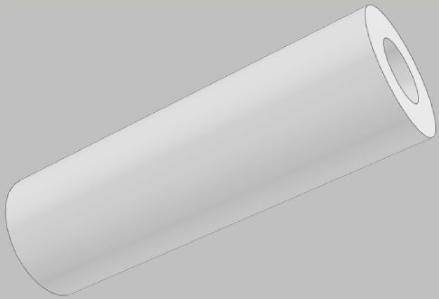
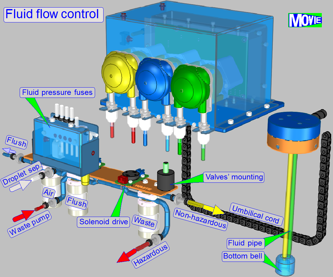
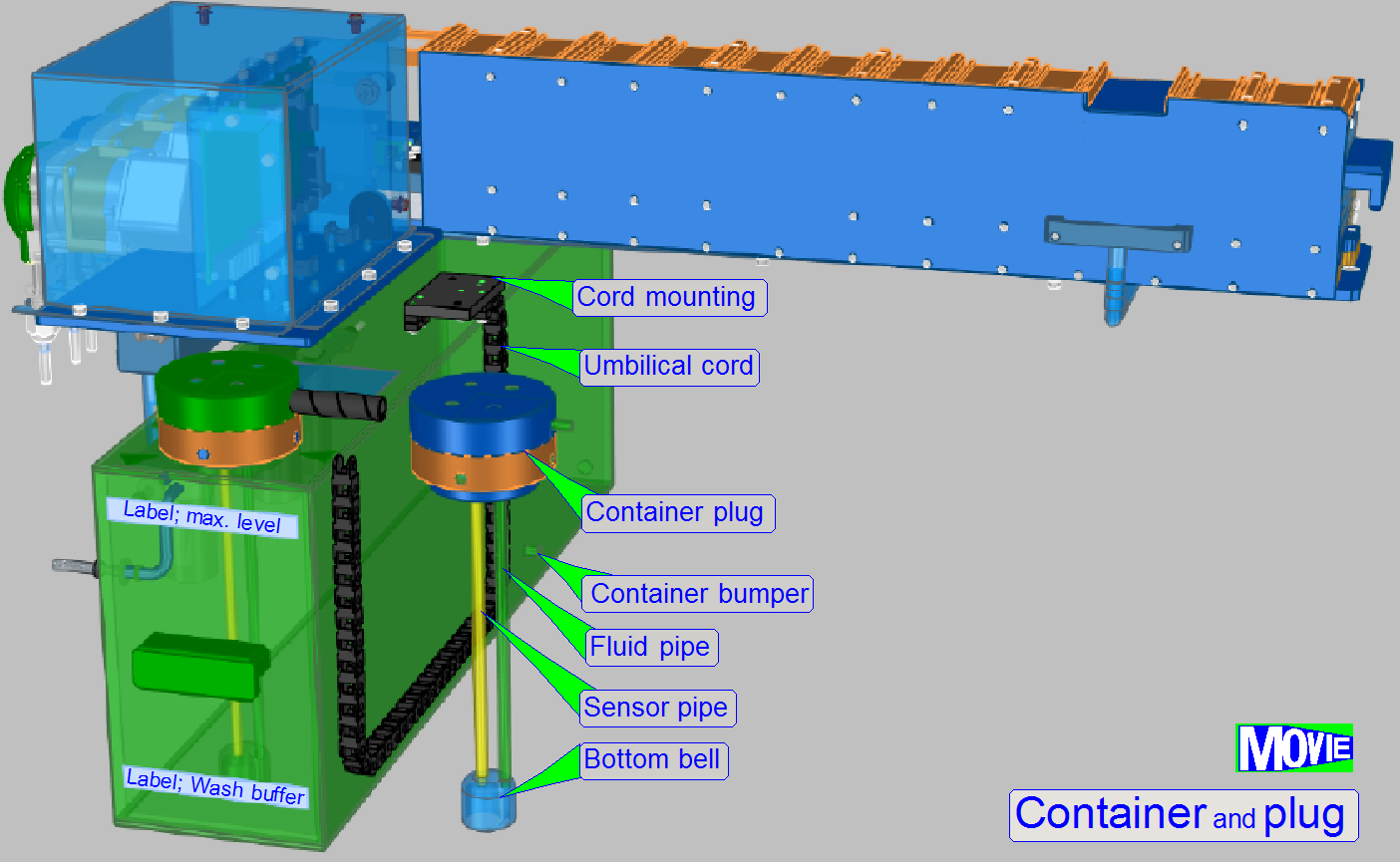 Umbilical cord
The
so called “umbilical cord” contains the flexible fluid pipe and the wires for
the pressure sensor. Both are covered by an energy chain.
Cord mounting
Fixes the fluid pipe, the sensor wires and is used as
mounting for the energy chain.
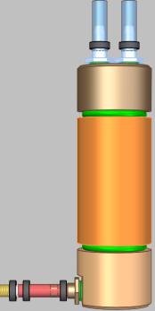
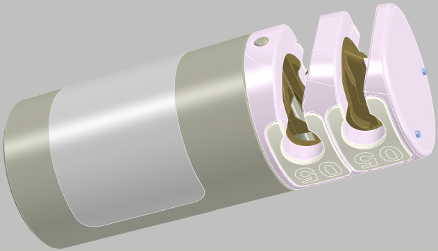
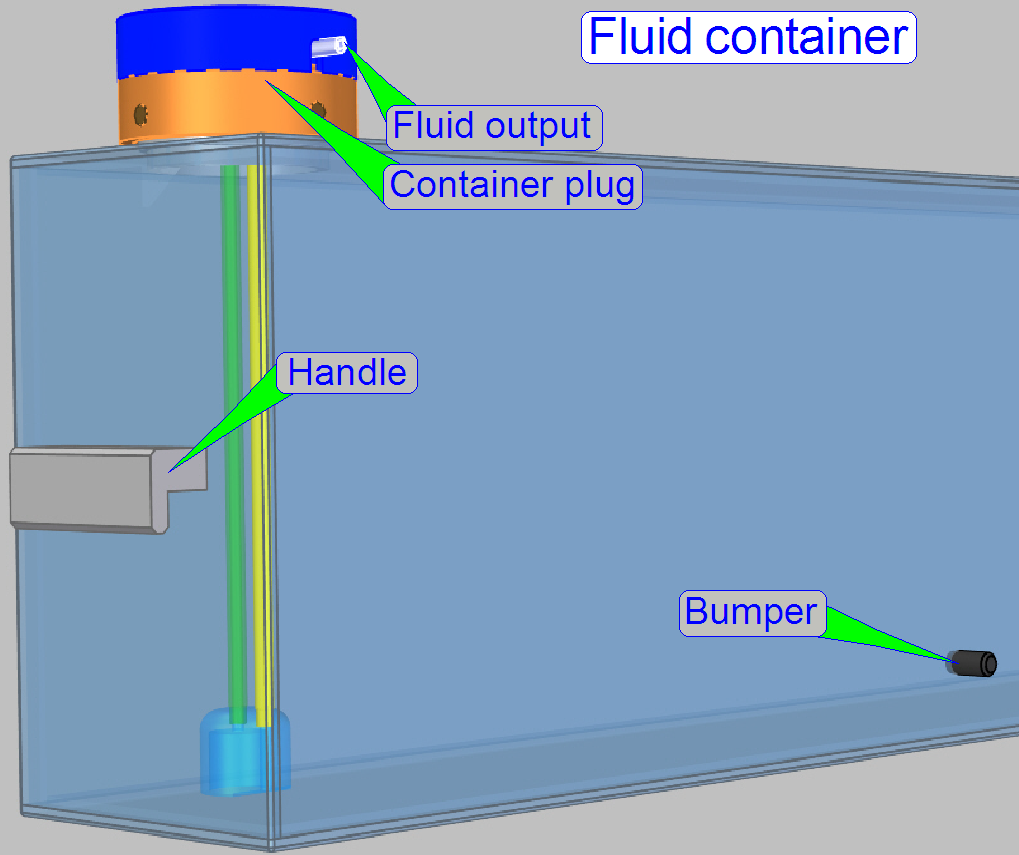
Container plug
The container plug contains the pressure sensor and
realizes the fluid flow from the container to the destination or waste fluid
into the container.
See also: “Container plug”
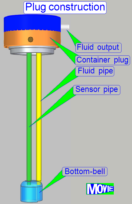 The
container plug and its construction allow the flow of the fluid out of the
container (washing and rinsing) or used fluid can be moved into the waste
container.
The
container plug and its construction allow the flow of the fluid out of the
container (washing and rinsing) or used fluid can be moved into the waste
container.
A pressure controlled sensor detects the states
“container empty”, “container full” and “fluid in the container”.
· Depending
on the fluid level in the container, the air in the sensor pipe will be
compressed or decompressed and so, the required fluid level states can be recognized.
By calibrating the pressure sensor, other container
fluid states like 1/4 full, 1/2 full and 3/4 full can be detected and
displayed.
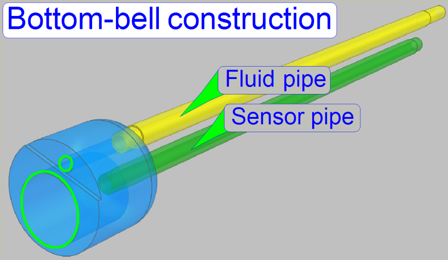
· If the
plug is inserted into the container vertically, the bottom-bell is filled with air
and so, the fluid will not stay in the sensor pipe. This way, the accuracy of
the sensor’s state is increased.
The spindle has 4 threads, so a very high precision of
longitudinal movement can be reached.
This precision is required to positioning the
appropriate nozzle to the fluid entry of the wash – rinse chamber.
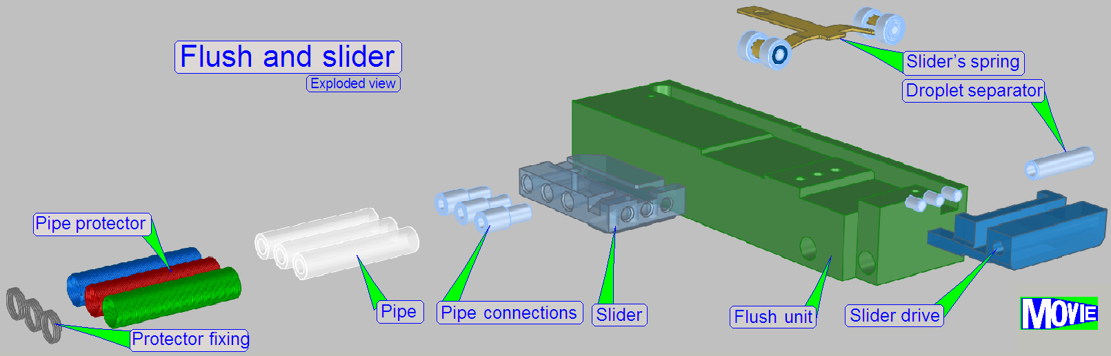
Slider
The slider is slippage free mounted to the spindle, so
a misalignment of the nozzles can not occur if the movement direction of the
slider is changed.
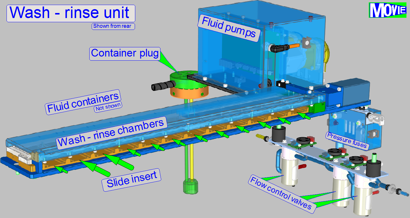
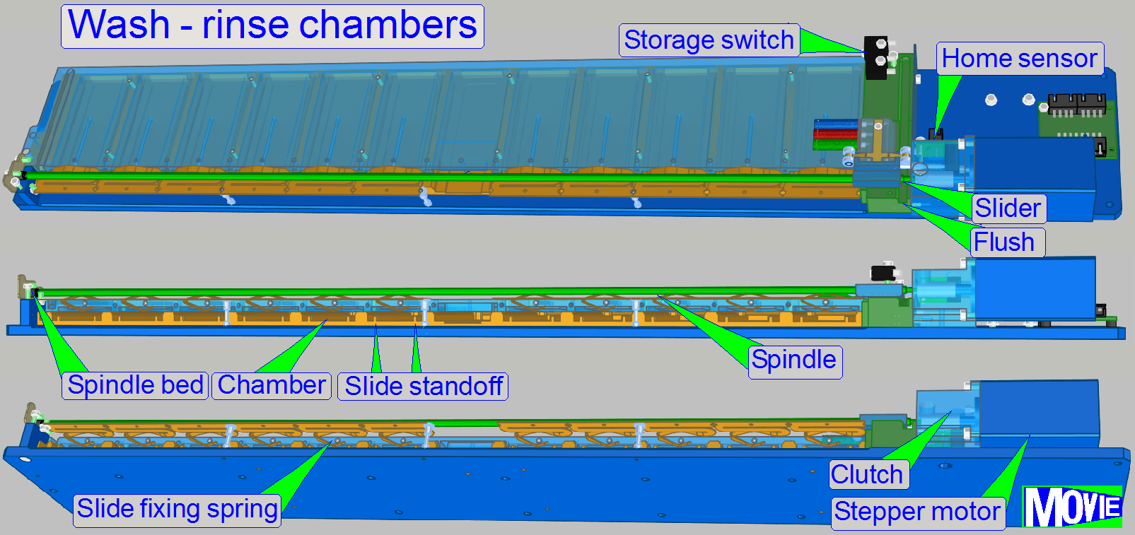
Chamber’s construction
Fluid
entry
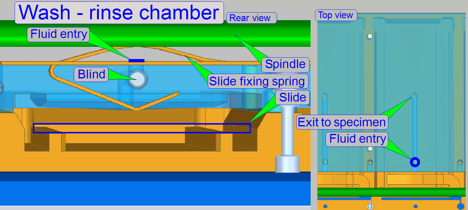
On the top side of the chamber there is the Fluid
entry hole through which the fluid flows into the center of the slide’s
specimen area.
The “blind” is permanently fixed to the rear end of this fluid path in
order to block the way of the fluid to that direction.
Slide
holding spring
As the slider arriving to the chamber, the slide fixing spring is pushed
downward and fixes so the slide in its position for the appropriate procedure.
The spring will be released as the slider moves to the next chamber.
Slide rack switch
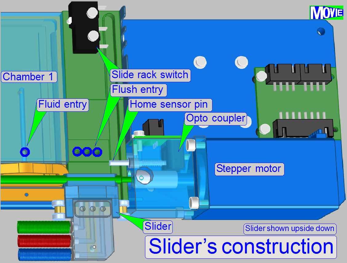
The
"Slide rack switch" (storage switch) is used to signal the presence
of the slide rack.
· If the
slide rack is present and inserted correctly, the switch is closed.
Stepper motor
The stepper motor rotates the spindle and moves so the slider over each
chamber or to the flush position.
The longitudinal movement resolution of the spindle
driven construction is 1μm so the nozzles can be moved accurately to the
fluid entry of the chamber.
· During
the processes “Apply fluid” and “Remove fluid” the nozzles are exactly placed
by software.
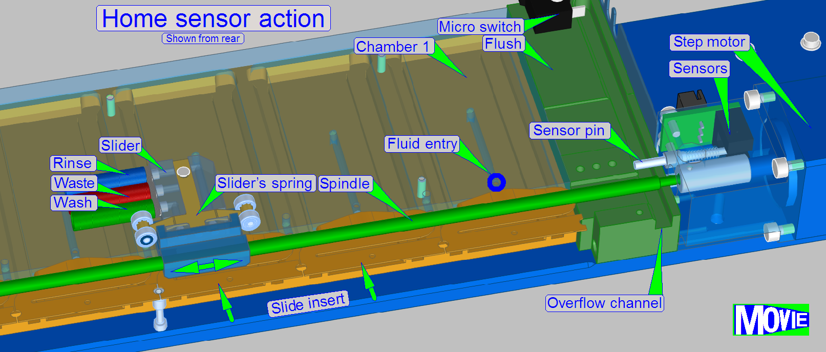
Home sensor
As the slider moves in direction to the spindle clutch
the slider arrives to the “Home sensor pin” and moves it in direction to the
opto-coupler. If the acting position of the opto-coupler is reached, the
optical path of the sensor is broken and the software will stop the slider’s
movement by switching off the stepper motor.
The fluid entry positions of the chambers are defined
in motor steps, counted from the home position.
The nozzle position of the slider is a number of motor
steps, relatively defined to the fluid
entry position of the chamber.
The slider contains the nozzles for the fluids; each fluid
type has its own nozzle.
 The slider can be moved over each wash and rinse chamber.
If the slide arrived over the chamber, the slider
moves the wash nozzle over the fluid entry of the chamber and the washing fluid
will be placed onto the specimen area.
If the incubation time of the washing fluid is over,
the nozzle with the waste tube will be moved to the fluid entry of the chamber
and the washing fluid will be removed from the sample surface; the fluid is
stored in the appropriate container (C3 or C4).
Now, the nozzle with the distilled water tube will be
moved to the fluid entry of the chamber and the rinsing process starts.
The rinsing fluid will be removed from the slide
surface with the nozzle “waste” and the fluid is stored in the appropriate
container (C3 or C4).
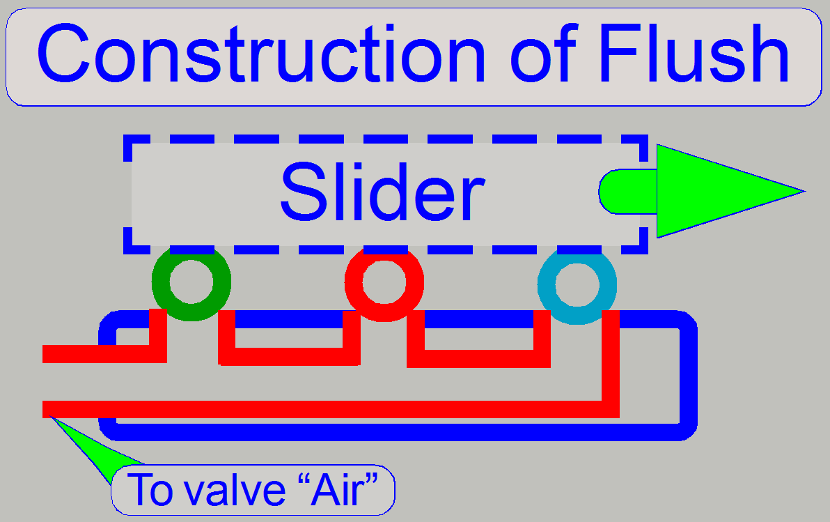
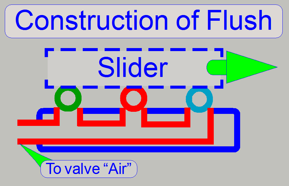
The flush unit is found at the home position of the
slider. It is used during software startup and software exit. The unit is
smaller than a slide chamber because only the nozzles are connected to each
other. In special conditions (software exit) the flush unit allows the removal
of the droplet separator’s fluid via the valve air.
See also “Start up software” and “Shut down software”.
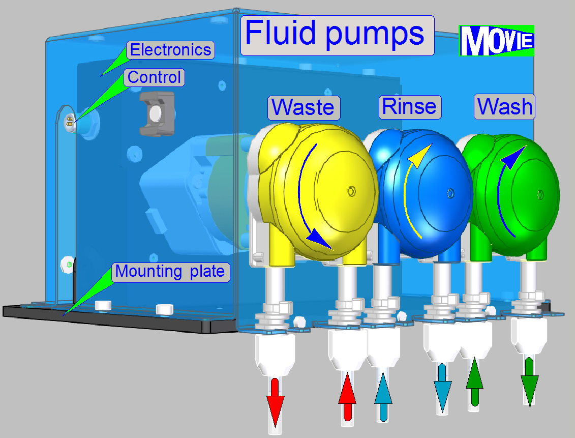
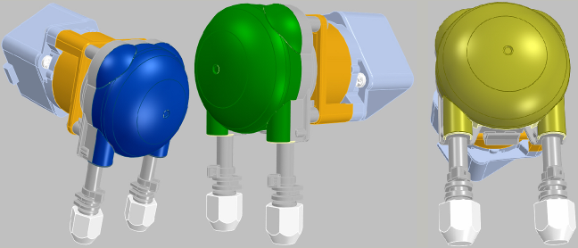
To avoid contaminating of the liquids washing, rinsing and waste,
the appropriate fluid is moved by a dedicated peristaltic pump.
The amount of
fluid to be carried is controlled by the pump. The pump is driven by a stepper
motor. The number of steps (the rotation angle of the pump's shaft) controls
the quantity of fluid and the time, elapsed between 2 step pulses is used to
control the speed of the carried fluid.
· If the
pump is switched off, the fluid path is broken; the pump’s behavior is like a
closed valve.
As the shaft rotates, the amount of the fluid is moved
from the tube input along the tube by the speed of the rotor until the fluid
amount arrives to the output.
See also “Materials”.
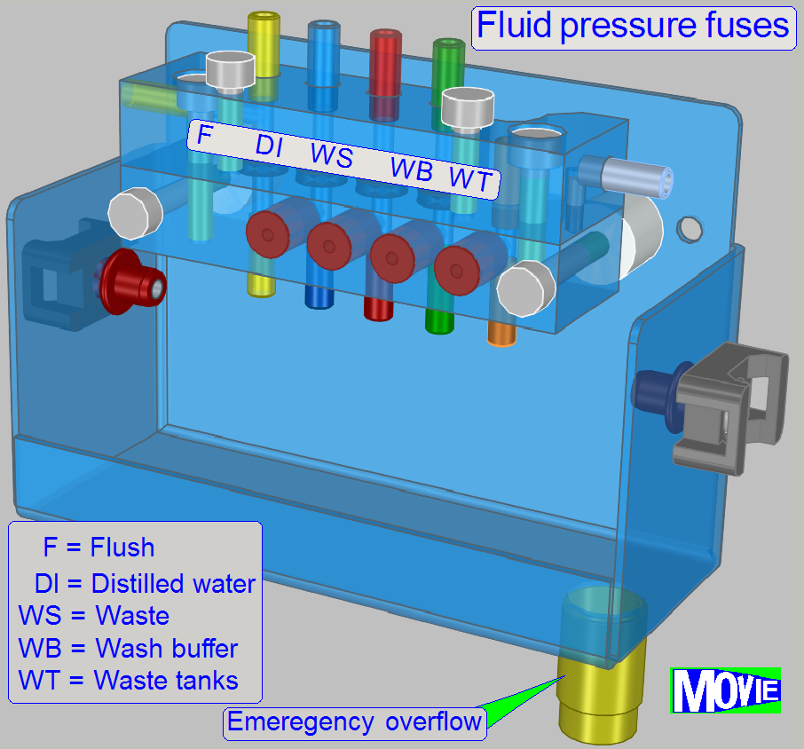
· Normally,
the fuses do not act, the fluid flows vertically thru the appropriate part of
the fuse unit.
Exception
· If the
fluid flow in the tube get obstruction for some reason (or the valves are wrongly
handled in the service program), the pressure in the tube system increases.
· To
avoid damaging of internal components and parts by aggressive fluids, the fuse
will act.
· Every
tube path has its own fuse.
See also "Emergency overflow system"
· Tubing
of fluid paths can be found in chapter “Fluid
paths”.
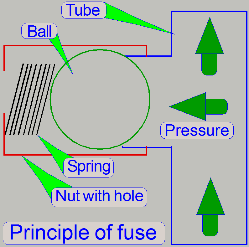 Principle of fuse
Normal
work
· Normally
the ball blocks the way in the direction to the nut's hole, and the fluid flows
vertically in the tube (as shown).
Exception
· As the
pressure in the tube increases and the force of the spring can not compensate
the pressure any more, the ball will not cover the tube stub and the fluid can
flow via the nut in the direction to its hole.
· After
this the fluid enters the fuse housing, gathers at the bottom of the housing
and flows out over the emergency overflow exit; see Fluid pressure fuses above.
See also "Emergency overflow system"
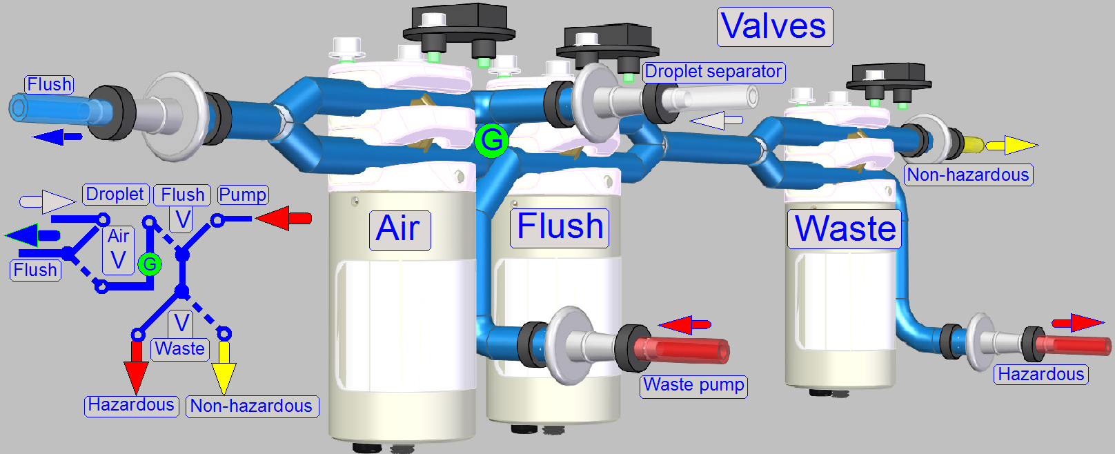
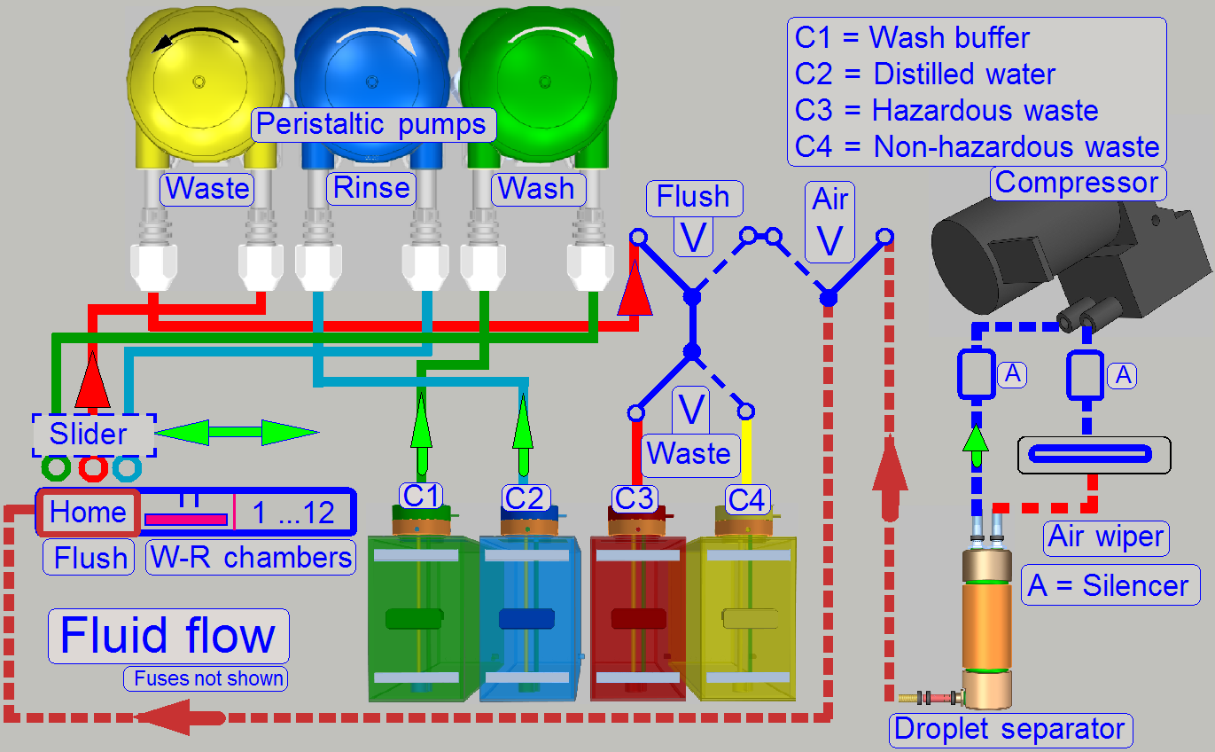
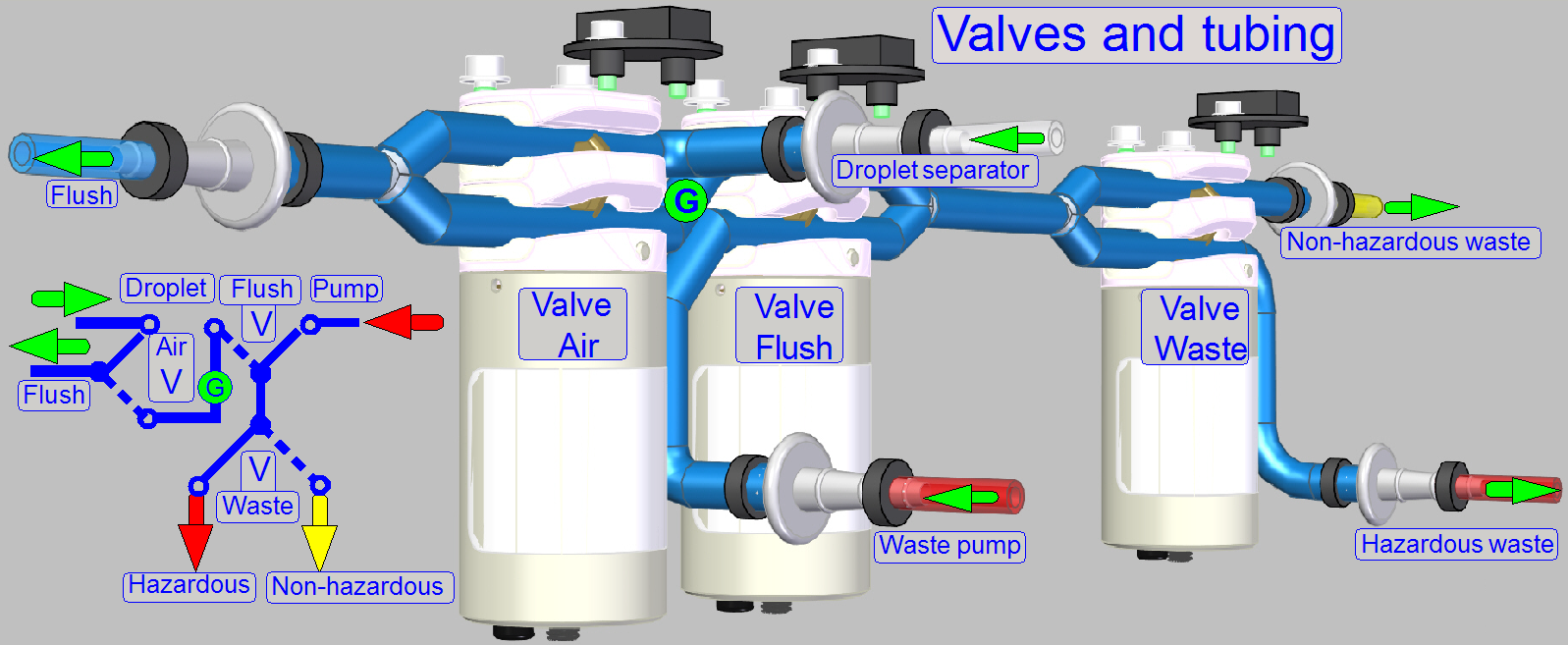
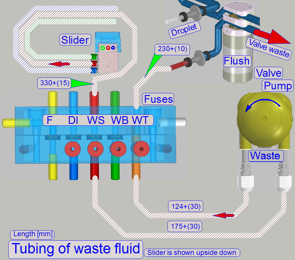
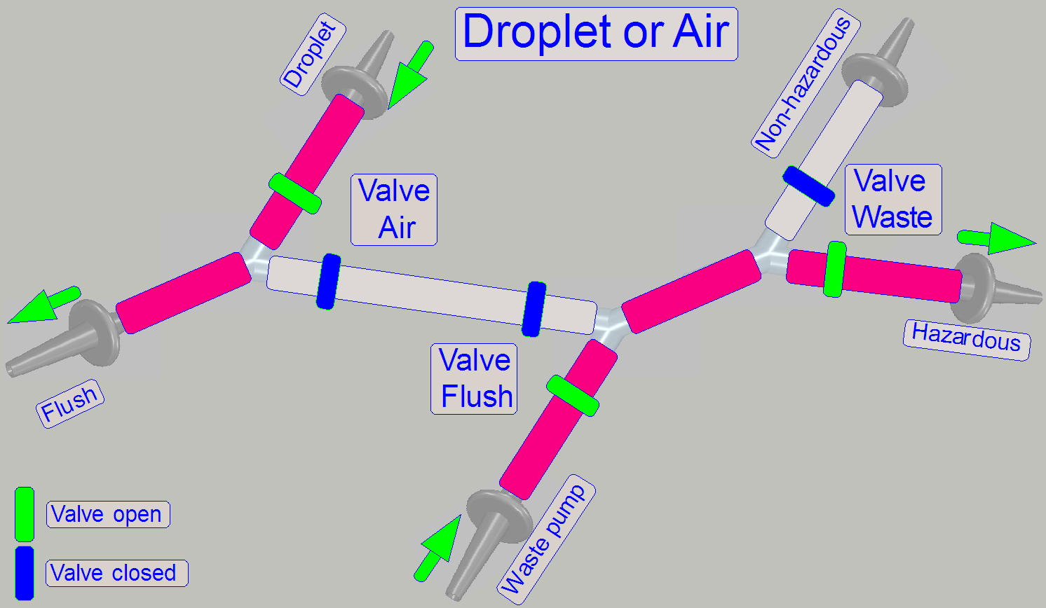
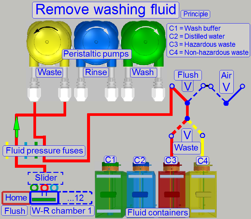
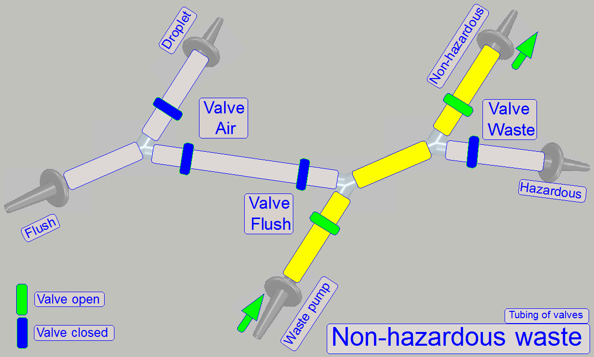
By using the 2-channel valves “Air”, “Flush” and
“Waste” and by switching on the peristaltic pump “Waste”, the flow direction of
the appropriate fluid can be controlled, depending on the task to be done and
kind of fluid to flow.
· The
valves are controlling always only the waste path of fluid!
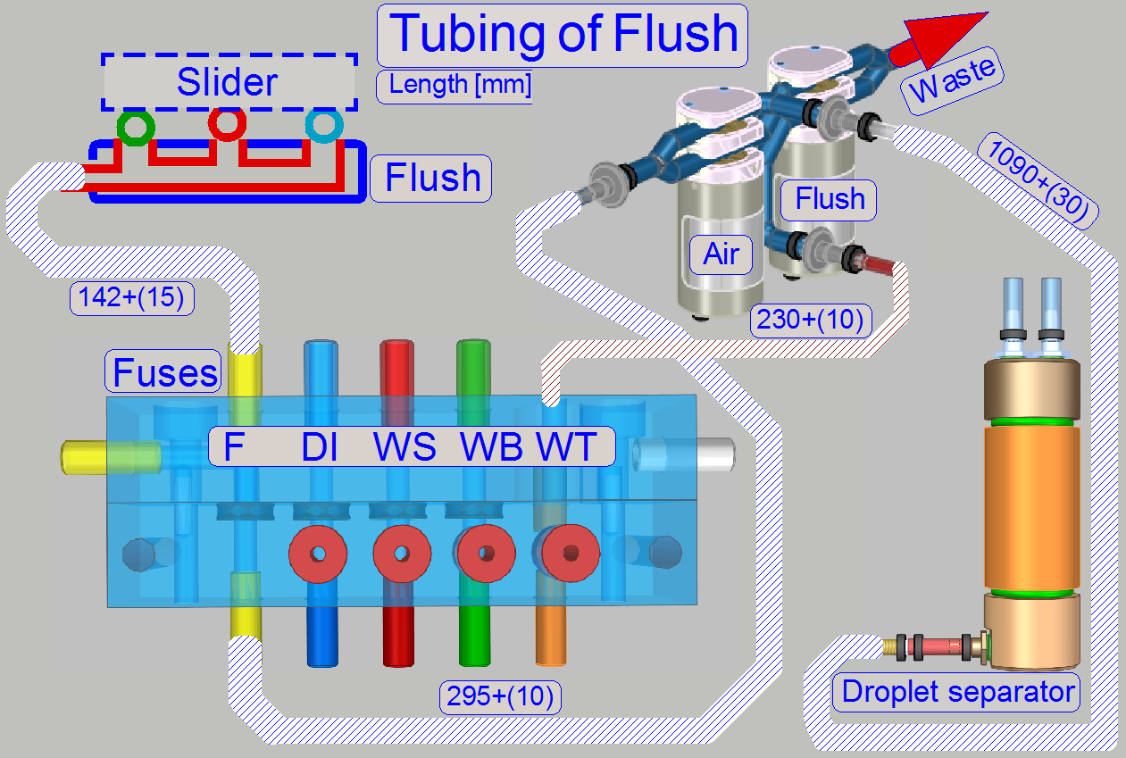
· Tubing
of fluid paths can be found in chapter “Fluid
paths”.
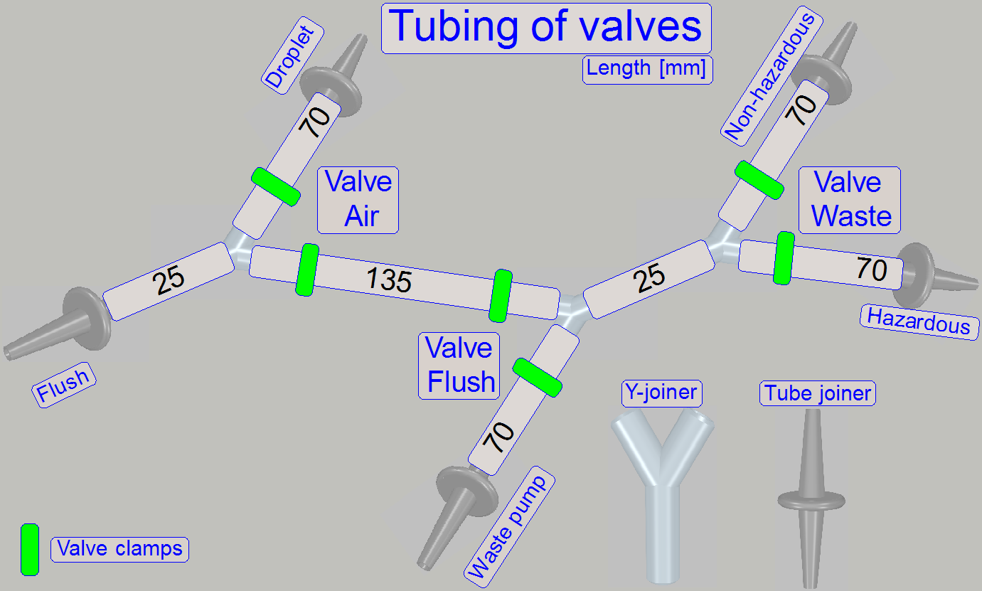 By opening or closing the clamp(s) of the appropriate valve
the path will be controlled.
By opening or closing the clamp(s) of the appropriate valve
the path will be controlled.
· Tubing
of the valves to other components can be found in chapter “Fluid paths”.
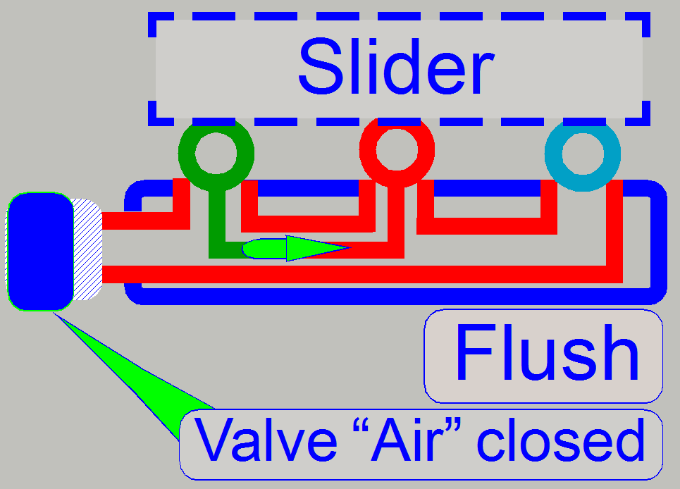
Depressurize flush path
By detaching
the pipe from its blind stub and moving this pipe end to the overflow basin and
opening the manual pipe clamp, the flush unit may be depressurized and fluid
can partly drained.
· If the
procedure is finished, please reconnect the pipe to its blind stub and close
the pipe clamp!
Flush path

Rinsing path
Washing path
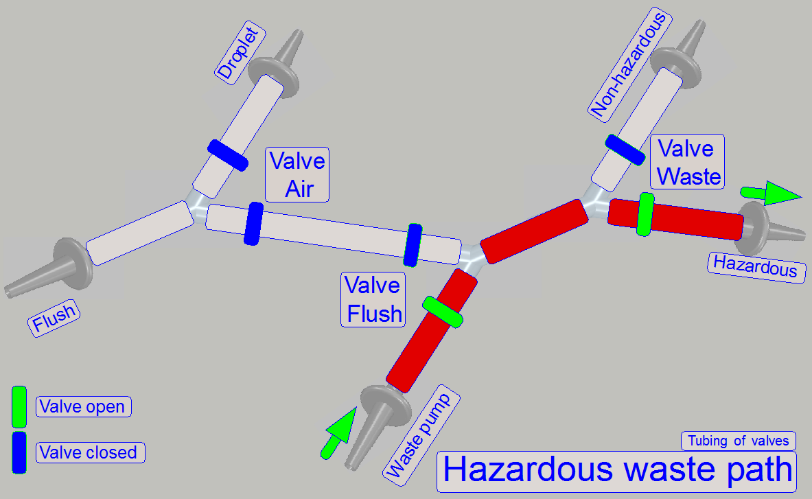
Waste path
The path,
“Hazardous waste” and “Non-hazardous waste” depends always on the stain,
removed during the washing and rinsing procedure.
· If the
removed stain, removed during the washing process is not poisonous and not
caustic; the removed washing fluid will be routed to the non-hazardous waste
container.
· Rinsing
fluid will be drained to the hazardous waste container if the stain was
poisonous or caustic otherwise, the rinsing fluid is drained as non-hazardous
waste.
The
fluid flow is usually divided into 4 phases
· Software
start
· Apply
fluid to the specimen
· Remove
fluid from the specimen
· software
exit
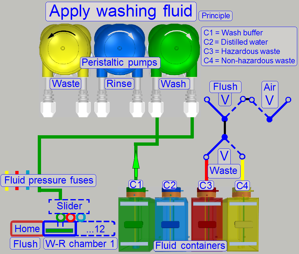
The fresh fluid will be driven directly from the fluid
container to the appropriate chamber in its dedicated pipe line system by its
own pump; so contamination of the fluid is avoided.
· During
startup the software, the slider will be moved to the Flush position (Home) and
the filling of the pipes with the appropriate fluid is done.
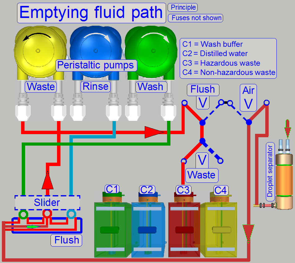
Because the waste path handles the fluid flow from
several possible sources and the waste fluid will be collected in 2 containers,
the source and destination path of the waste fluid will be selected by valves.
· During
exit the software, the fluid of the Air dropper will bee removed and then the
pipes of the valve system will be emptied (filled with air).
Because the pressure of the pump may be much more then
required “Fluid pressure fuses” are implemented; these fuses acting only in emergency
states.
In the
following, the fluid flow will be separated by source, destination and task.
During the startup procedure of the software the tubes
and pumps for the washing and rinsing process have to be filled with water or
washing fluid respectively and the fluid supply tubes must not contain air
bubbles.
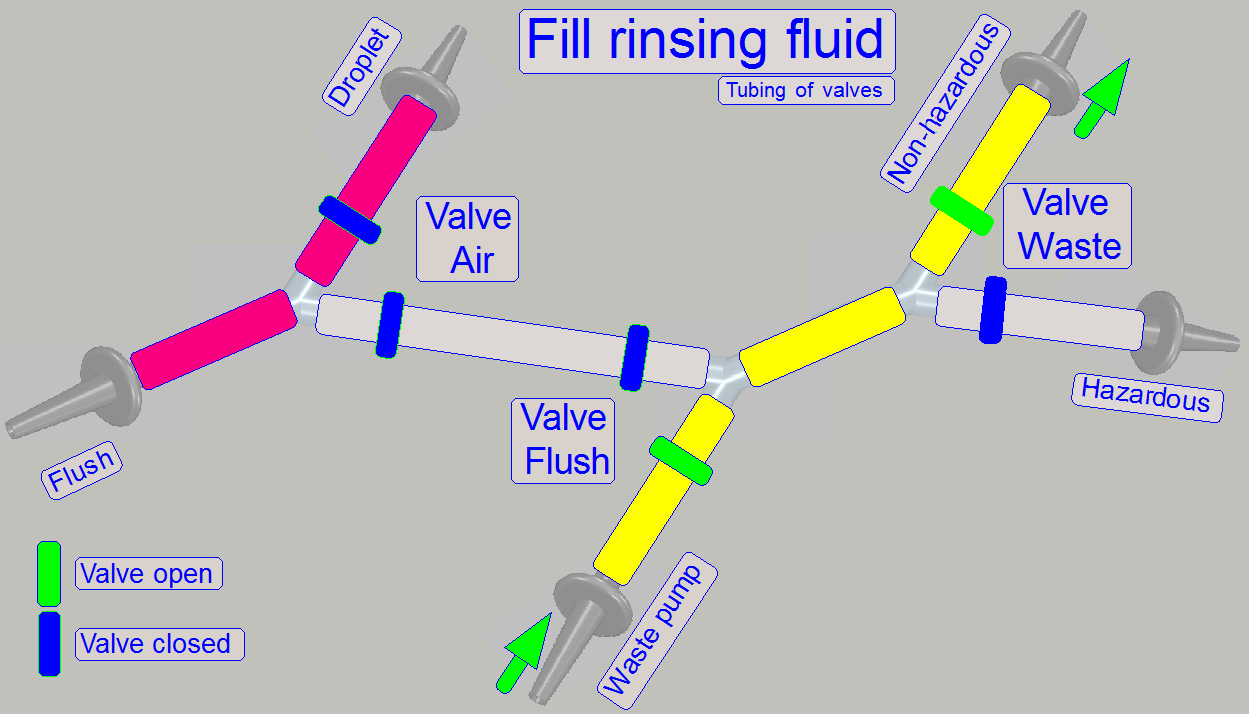
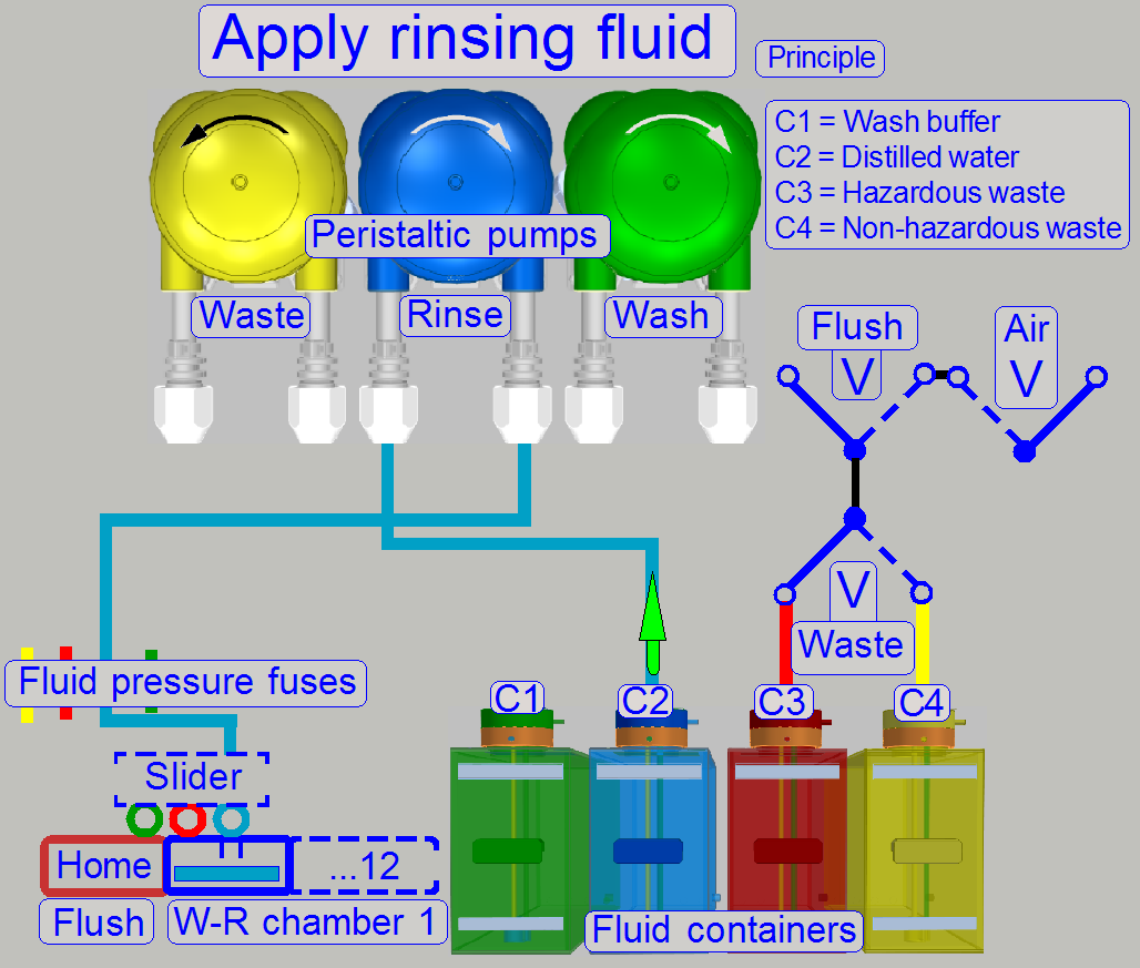
Fill rinsing fluid
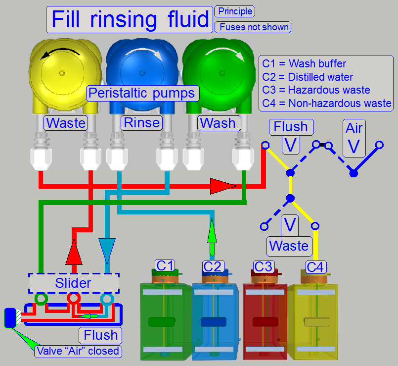
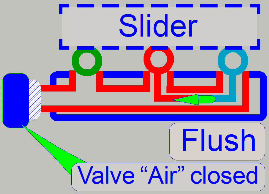
First, the slider is moved to the flush (home)
position by the software. The rinsing pump and the waste pump are switched on.
The rinsing pipes will be filled with distilled water. The fluid moves through
the Rinse pump and the fuses to the slider. The flush path to the valve
"Air" is blocked.
Remark
· The
fuses are not shown on the image. For fuse implementing, see “Fluid pressure fuses”.
· The
piping of the container C1 is not shown, because it is excluded during this
operation.
· Because
the wash pump does not work, its behavior is like a closed valve.
The fluid is moved from the waste nozzle via the waste
fuse, the waste pump to the valves.
Rinsing fluid is non-hazardous, so the fluid is pumped
into the non-hazardous waste container.
The rinsing pump is switched on and pumps distilled
water to the appropriate slider opening. In the same time, the waste pump moves
the fluid into the non-hazardous waste container.
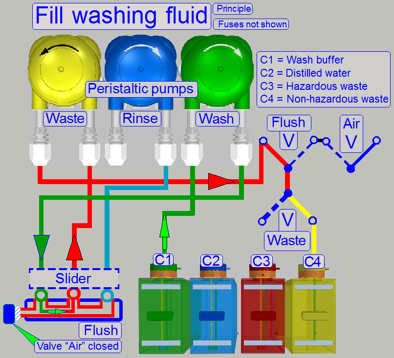 Fill washing fluid
The slider stays in the flush (home) position. The
washing pump and the waste pump are switched on.
The pipes of the washing path will be filled from the
wash container via the wash pump.
The washing fluid arrives to the slider’s nozzle and
the fluid will be removed from the slider nozzle via the waste path.
The washing fluid itself is non-hazardous, so fluid is
pumped to the non-hazardous waste container.
Remark
· The
fuses are not shown on the image. For fuse implementing, see also “Fluid pressure fuses”.
· The
piping of the container C2 is not shown, because it is excluded during this
operation.
· Because
the rinse pump does not work, its behavior is like a closed valve.
The wash pump is switched on and pumps washing fluid
to the appropriate slider's opening, during the waste pump moves the fluid to
the non-hazardous waste container.
During this process the Air wiper’s droplet separator
fluid container will be emptied.
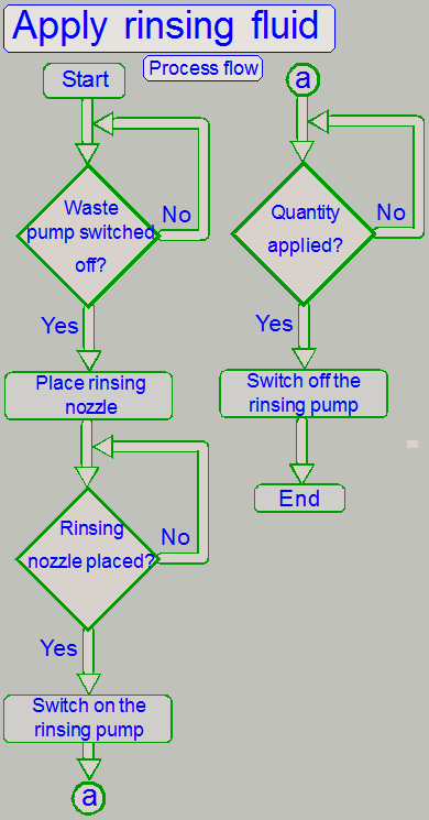
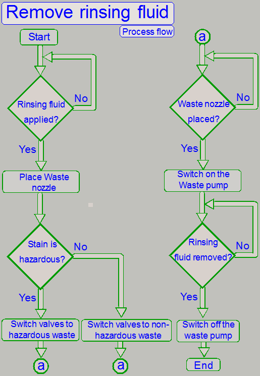
See the flowchart on the right; only components for
the process are shown.
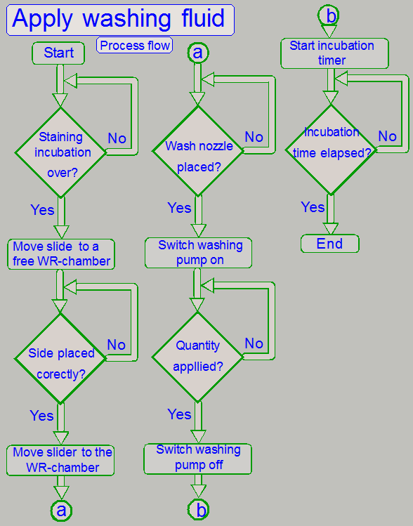
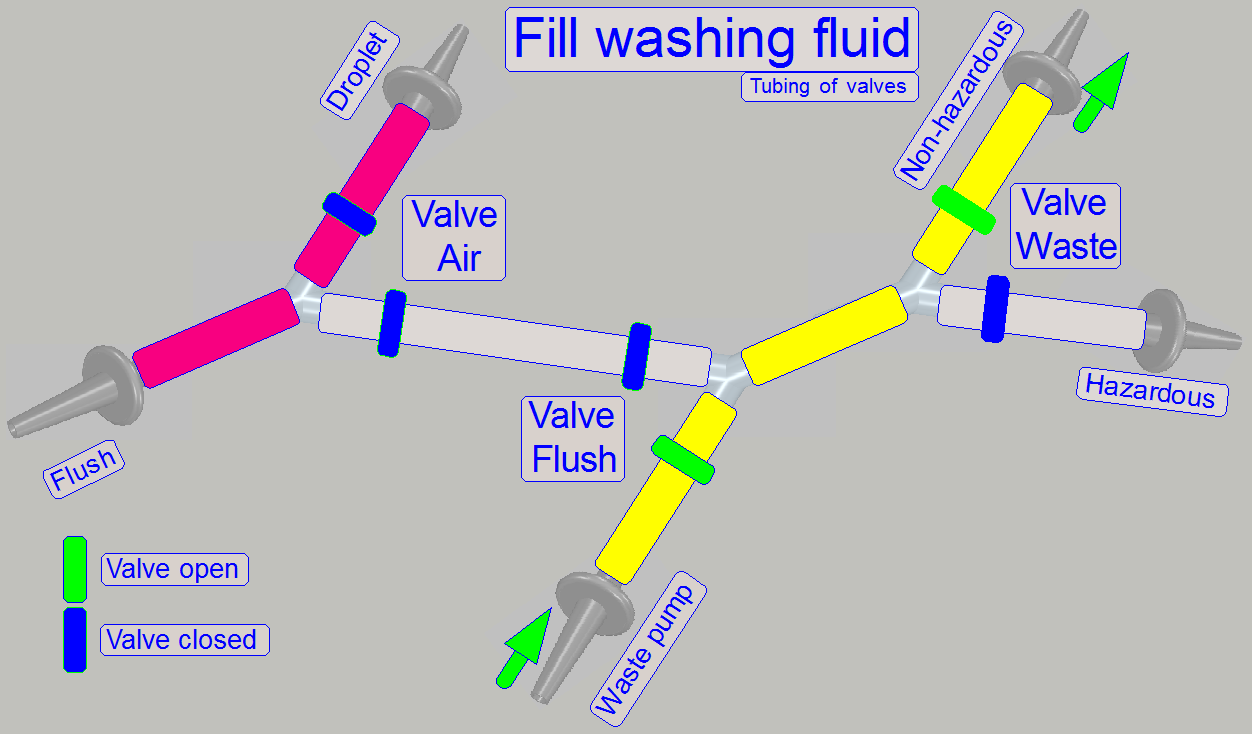
The washing fluid remains on the specimen for 1 … 10 minutes, depending
on the stain properties; the exact time is defined in the process protocol.
· The incubation of
the washing fluid is done in the actual WR-chamber.
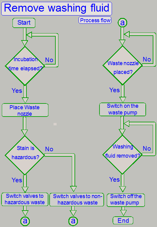
If the incubation time of the washing fluid is over, the fluid will be
moved to a waste container, depending on the stain was hazardous or not.
The washing fluid is removed to the hazardous waste container or to the
non-hazardous waste container!
· If the stain is
hazardous, the washing fluid is moved to the hazardous waste container!
The distilled water is applied to the specimen after
the washing fluid is removed.
· There
is no incubation time of the rinsing fluid.
As the rinsing fluid applied to the specimen, the
slider's position is changed to the waste nozzle and the rinsing fluid is
removed into a waste container (C3 or C4).
· If the reagent
(stain) was hazardous, the rinsing fluid is moved into the hazardous waste
container (C3)!

After
the rinsing process is finished, finest water drops may remaining on the
specimen. Because any extraneous material may affect the specimen’s scan
quality, residues of the specimen staining process have to be removed before
cover slipping.
The specimen must not be heat up for this procedure,
residues are removed by the “Air wiper”.
As included in the name, the residues of the creation
process will be removed by blowing air over the prepared specimen and so,
finest water drops and other residues of the creation process are removed.
Principle
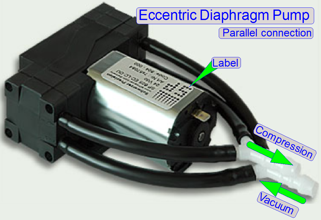
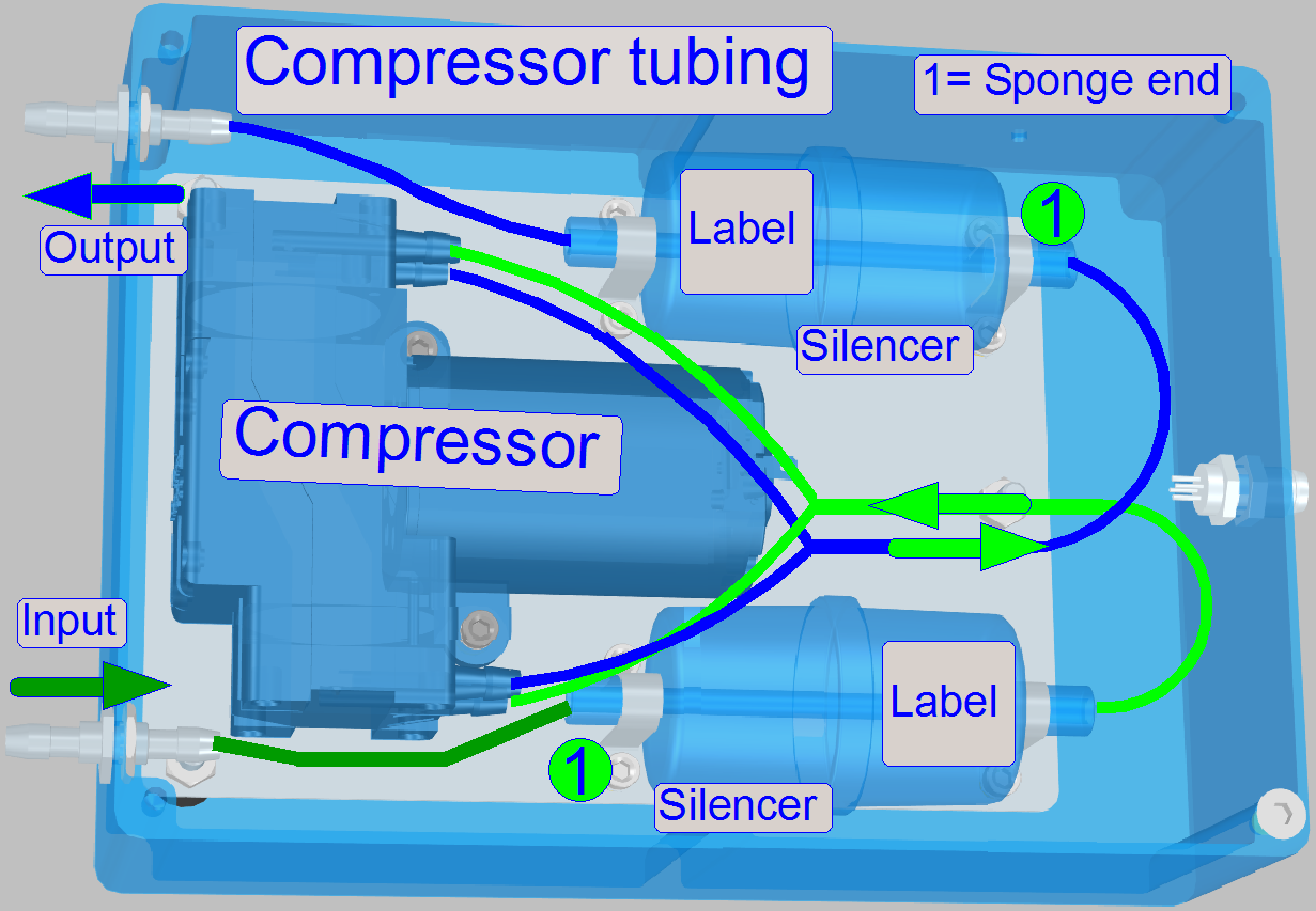
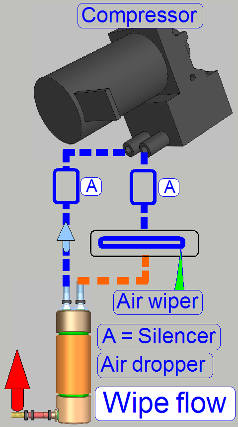 If the real wiping process starts, the compressor will be
switched on. The compressed air arrives to the nozzle of the “Air wiper” in an
angle of 45º by crossing the silencer (A). The nozzle of the air wiper is
a bit larger than the width of the slide, so the entire surface of the slide
will be blown with compressed air. The removed fluid will be sucked into the
droplet separator (air dropper), where the fluid will be separated from the
air. After crossing a second silencer (A), the droplet separator's output is
connected to the vacuum input of the compressor and the air loop is closed.
If the real wiping process starts, the compressor will be
switched on. The compressed air arrives to the nozzle of the “Air wiper” in an
angle of 45º by crossing the silencer (A). The nozzle of the air wiper is
a bit larger than the width of the slide, so the entire surface of the slide
will be blown with compressed air. The removed fluid will be sucked into the
droplet separator (air dropper), where the fluid will be separated from the
air. After crossing a second silencer (A), the droplet separator's output is
connected to the vacuum input of the compressor and the air loop is closed.
· The
water reservoir of the droplet separator will be drained in defined intervals,
if the software will be shut down and the slider of the wash-rinse unit stays
in the flush position.
Components
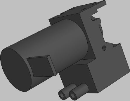
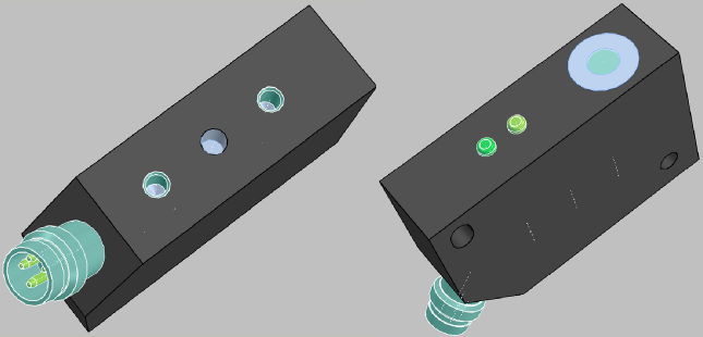
Droplet separator
The air,
arriving from the air wiper is contaminated with finest droplets as a result of
the wiping procedure.
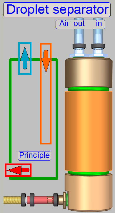 These droplets are separated from the air by gravity and
are collected in the lower part of the device. During shut down the software,
the droplet separator will be emptied via the valve “Air” and the “Flush” part
of the sliders home position.
These droplets are separated from the air by gravity and
are collected in the lower part of the device. During shut down the software,
the droplet separator will be emptied via the valve “Air” and the “Flush” part
of the sliders home position.
If the device does not contain anymore water, the
tubes of the waste fluid path are filled with air via the "Air input"
of the device.
See also: “Shut down software”
Working
· 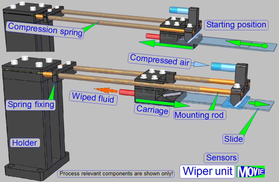 If
the slide will be inserted into the wiper position by the slide mover, the
carriage moves in direction to the holder and the compression springs will be
stressed.
If
the slide will be inserted into the wiper position by the slide mover, the
carriage moves in direction to the holder and the compression springs will be
stressed.
· If the
slide is inserted by about 60mm, the compressor is switched on and the
compressed air arrives onto the sample surface of the scan area in an angle of
45º and the wiped fluid will be moved into the air dropper.
· Now,
the slide mover moves the slide slowly backward, out of the wiper position and
the liquid on the slide surface will be moved to the inner edge of the slide.
· The
compression springs pushing the carriage always against the slide inner edge
and the wiped fluid can be moved away.
· If the
starting position is arrived again, the wipe procedure is finished and the
compressor will be switched off.
Remark
The working principle of the “compression spring” is
not shown correctly!
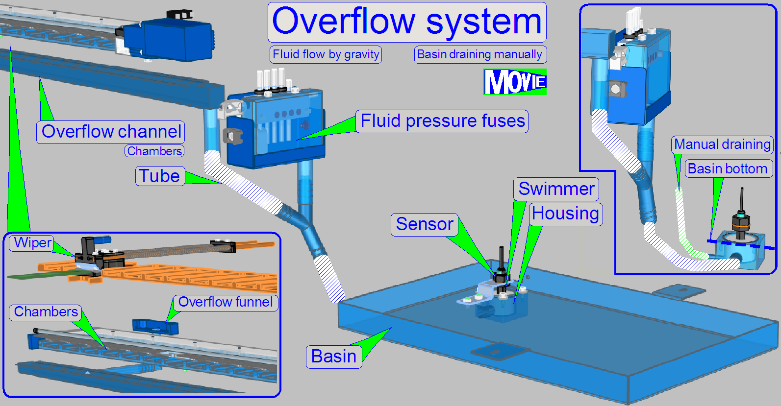
In emergency conditions
fluid may flow out of its dedicated path. To protect the equipment from damage
by partially aggressive fluid, an overflow draining system is realized.
Source
of overflow may be
· Any chamber of the
wash – rinse unit
· The rear of the
wiper bay
· Any fluid pressure
fuse
· Flush unit
The fluid is collected by the “Overflow funnel” (Wiper rear), the “Overflow
channel” (any wash – rinse chamber and flush unit) and the fuse housing; the
flow is realized by gravity.
The overflow fluid is drained to the basin below the slide scanner; a
swimmer driven sensor is used to indicate to the software that fluid is present
in the basin.
At the lowest point of the swimmer housing, the fluid can be drained
manually to an external pot by the help of a syringe and should be disposed as
hazardous waste fluid.
· To drain the
basin, remove the overflow drain tube from its holder and connect a syringe
with a capacity of 50ml and suck out the fluid.
See also: “Truss”
|
Image(s) |
Component |
Manufacturer |
Remark |
|
|
|||
|
|
|
|
Air dropper |
|
|
|||
|
|
|
KNF NMP-05-B |
Vacuum
pump (compressor) -pdf- |
|
|
|||
|
|
|
BUS0009 |
Distance
measuring sensor |
|
|
|||
|
|
|
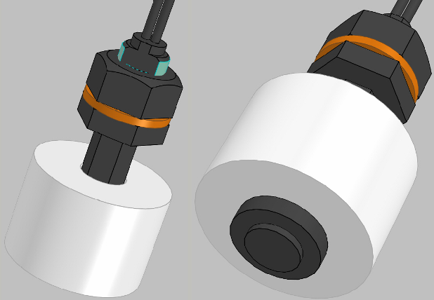
59630 |
Float sensor
|
|
|
|||
|
|
|
WPX1-X1-8FA2-WM4 |
Peristaltic
pump Color Yellow,
green, blue |
|
|
|
||
|
|
|
Used with solenoid operated products |
|
|
|
|
Bondex ID3.0-OD4.0-01549 ID3.0-OD5.0-00072 ID4.0-OD6.0-00078 Saint-Gobain |
Fluid pipe Two 6-inch section of tubing
supplied with valve. Fluid pipe -pdf- Fluid pipe -pdf- |
|
|
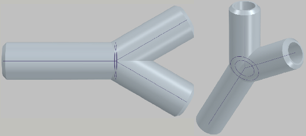
|
Y-splitter Two 6-inch section of tubing
supplied with valve joined by a "Y" connector. |
|
|
|
|||
|
|
|
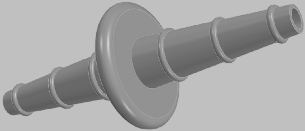
Bovimex K510 |
Tube
joiner |
|
|
|||
|
|
|
|
|
|
|
|
|
|
|
|
|
|
|
|
|
|
|
|
|
|
|
|
|