Construction; iSaCS Scanner
For technicians and
partly for sales managers!
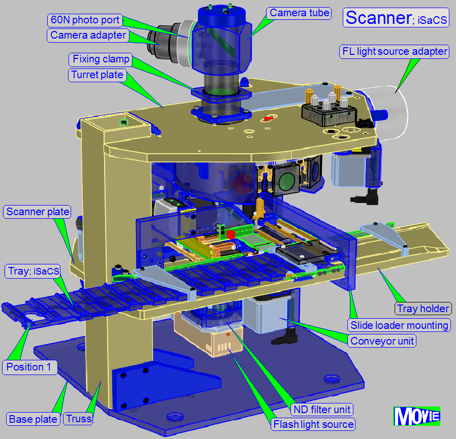
The scanner of the 3DHISTECH iSaCS consists of the
following main components:
1.
Base plate
with Scanner truss
2.
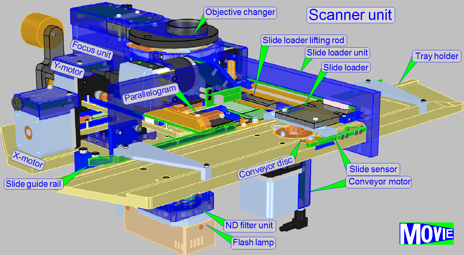
Scanner unit
3.
Image path with objective
changer and tube lens
4.
60N Photo port with scan camera PCO.edge 5.5Mp (not
shown)
5.
Tilting table with immersion liquid feeder, objective
changer and entire image path
6.
Mounting for the FL illumination unit table; for Lumencor SPECTRA
light engine
7.
Power tower;
with power
supply and main control
electronics
Scanner
plate with the mounting to the truss
RGB brightfield
scan illumination
Tray holder with
conveyor unit
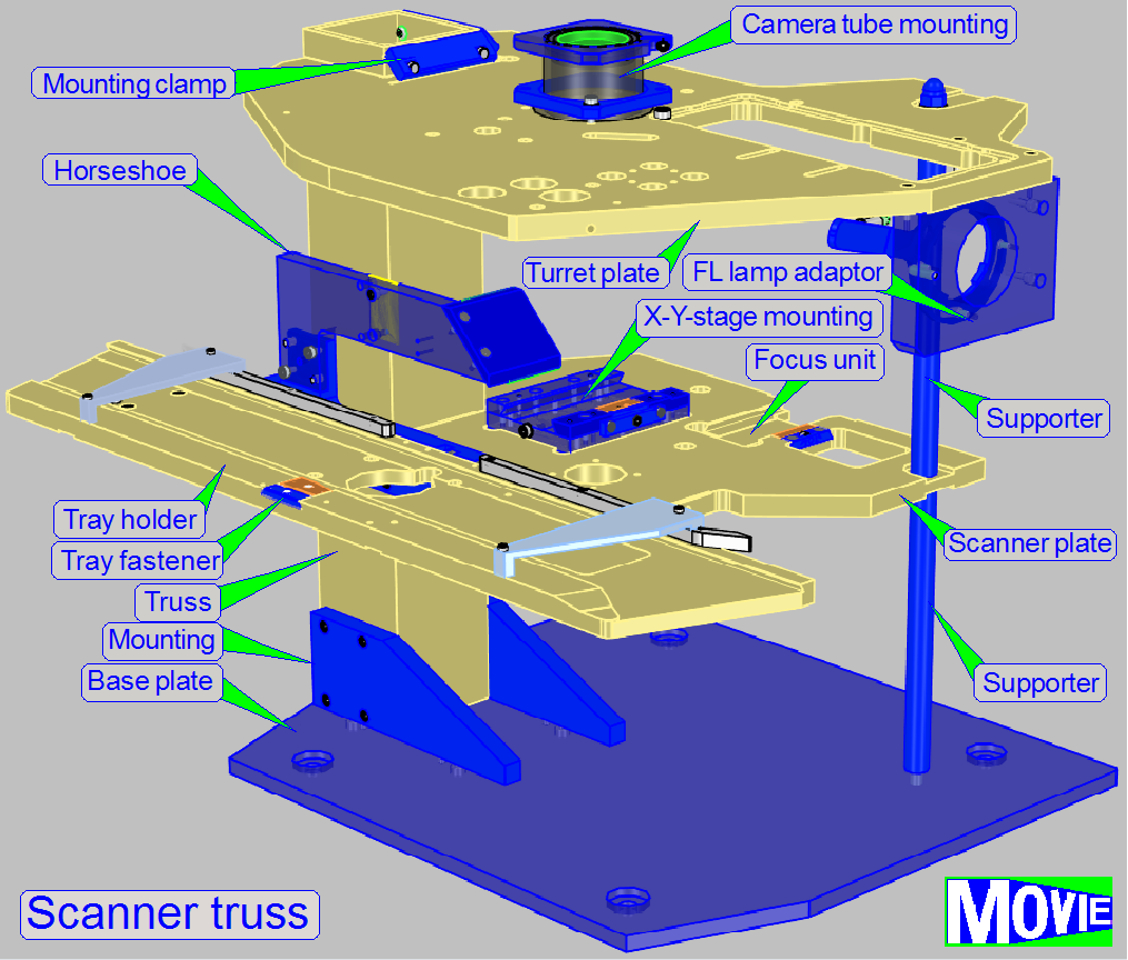
The scanner unit consists of:
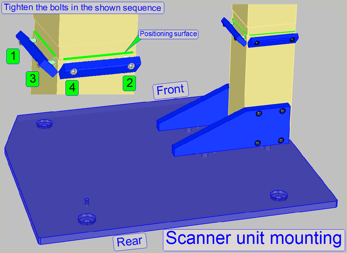
· Truss with mounting clamps for the Scanner plate
· The tightening
sequence of the mounting bolts is required to fit the scanner plate’s
components into the optical axis correctly!
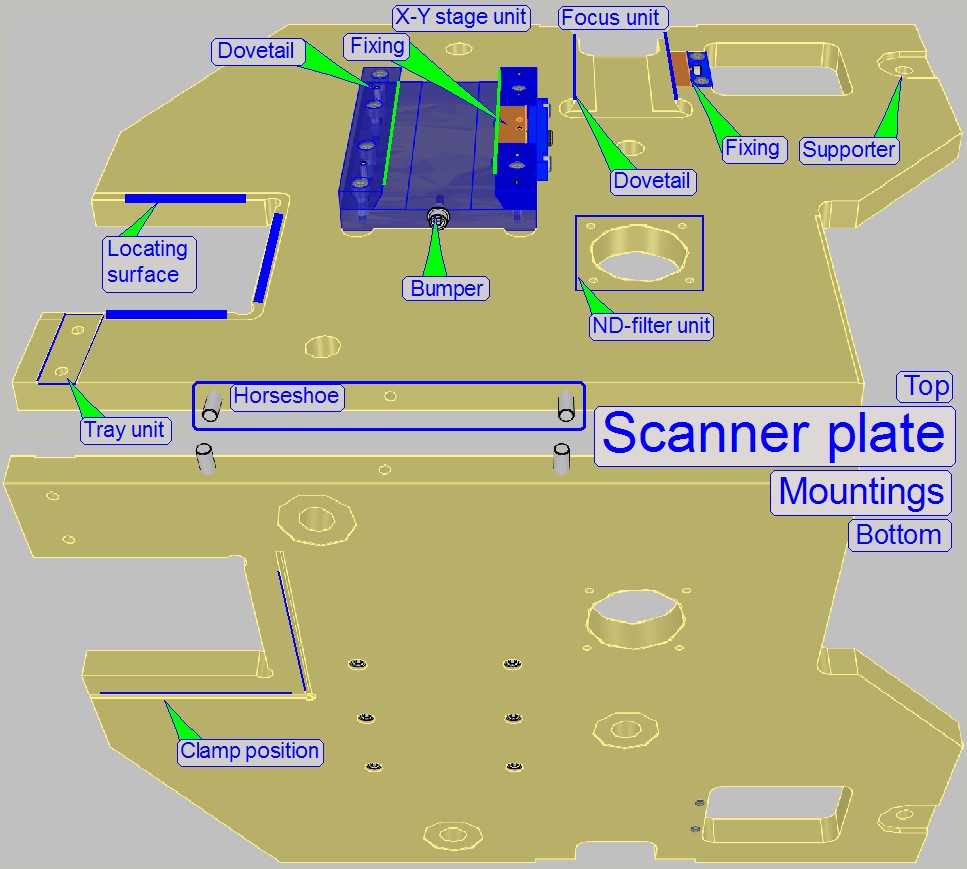
The scanner plate contains the mountings for the units
· Truss,
with Locating surfaces
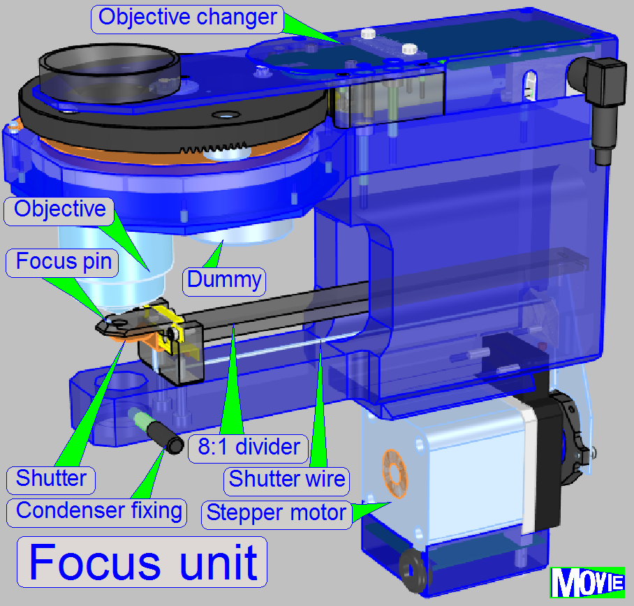
· Focus
unit’s dovetail mounting
· Focus unit’s dovetail fixing
· X-Y-stage
unit’s dovetail mounting
· X-Y-stage unit’s dovetail fixing
· Preview
unit’s horseshoe mounting
· ND filter unit
mounting
· X-Y-stage
unit bumper with mounting
To define the plane of the scanner unit in relation to
the turret unit and to ensure the straightness of the optical axis, locating
surfaces are used.
![]() “Scanner unit mounting” and
“Tightening sequence”
“Scanner unit mounting” and
“Tightening sequence”
Preview
unit’s horseshoe mounting
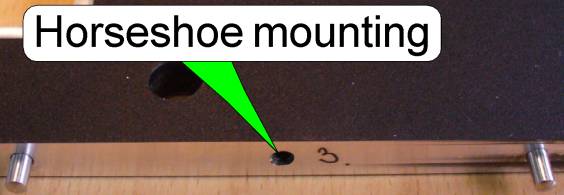 The
horseshoe mounting contains two fixing pins to define the position and a
threaded hole for the mounting bolt.
The
horseshoe mounting contains two fixing pins to define the position and a
threaded hole for the mounting bolt.
X-Y-stage unit
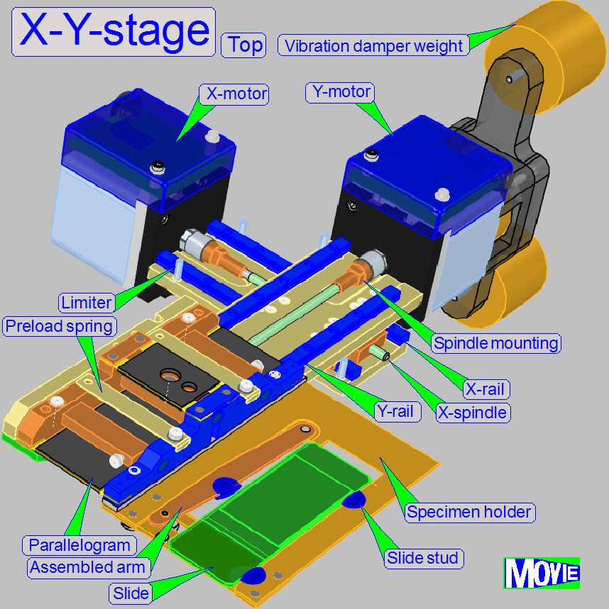
The
X-Y-stage unit can be removed or mounted only, if the entire base plate with
scanner plate is removed!
Dismount
the X-Y-stage unit
- Remove the
Focus unit
- Remove the
X-X-stage unit
Mount
the X-Y-stage unit
- Mount the
X-X-stage unit
- Mount the
Focus unit
X-Y-stage unit bumper with mounting
The
distance of the X-Y-stage unit in relation to the tray unit is defined by the
X-Y-stage unit bumper.
- Remove the
condenser unit
- Remove the
Focus unit
Mount
the focus unit
- Mount the
Focus unit
- Mount the
condenser unit
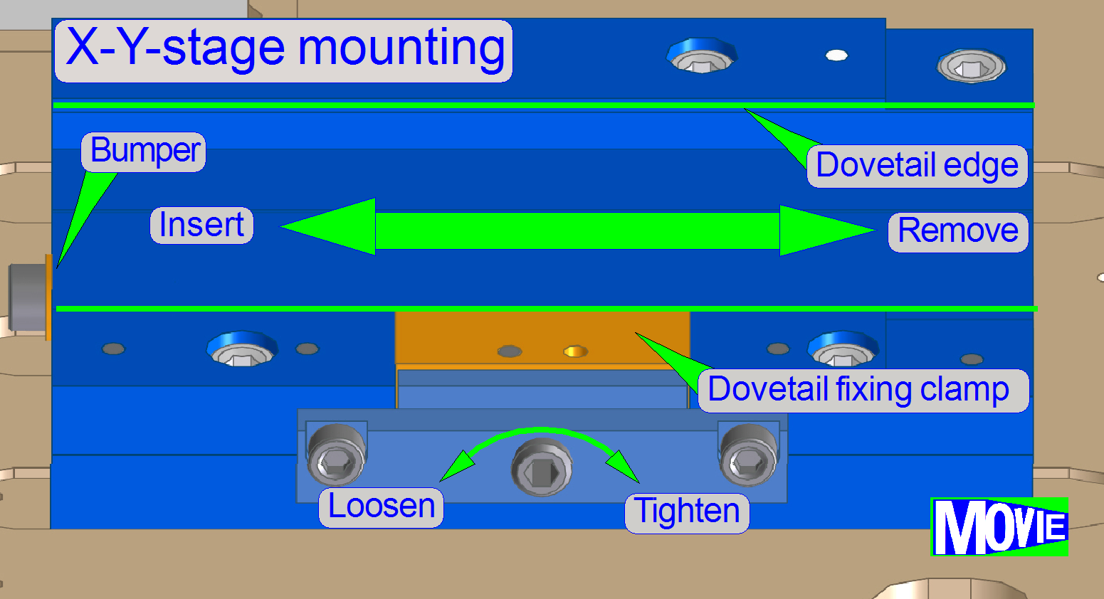
Focus unit’s dovetail mounting
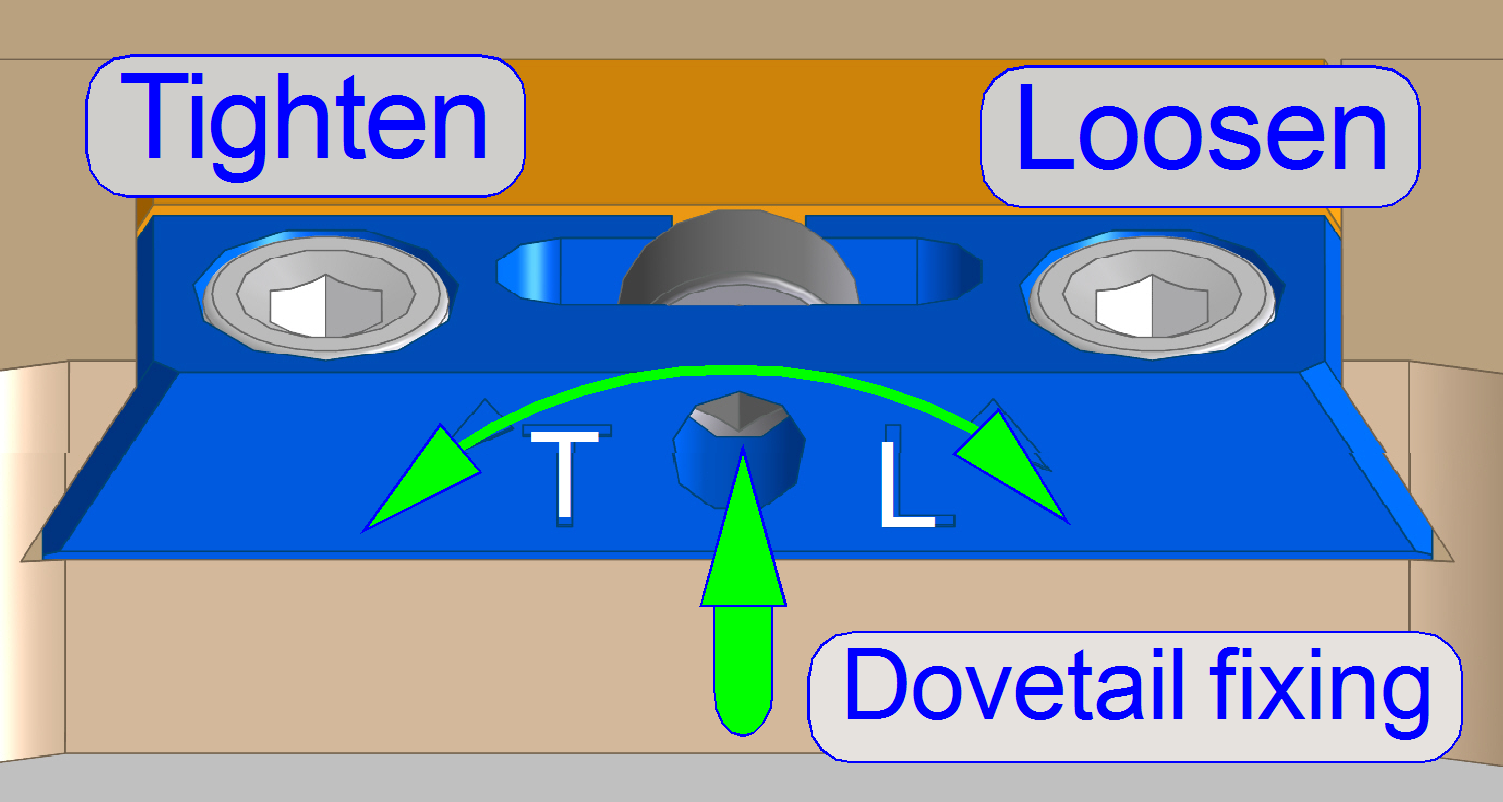
The mounting of the focus
unit and the mounting of the X-Y-stage unit are realized with dovetails; these
are hold by dovetail fixing clamps.
- Focus unit: Rotate
the 2.5 hex key
wrench clockwise to open (loosen) the dovetail clamp.
- X-Y-stage unit: Rotate the 2.5 hex key wrench
counterclockwise to open (loosen) the dovetail clamp.
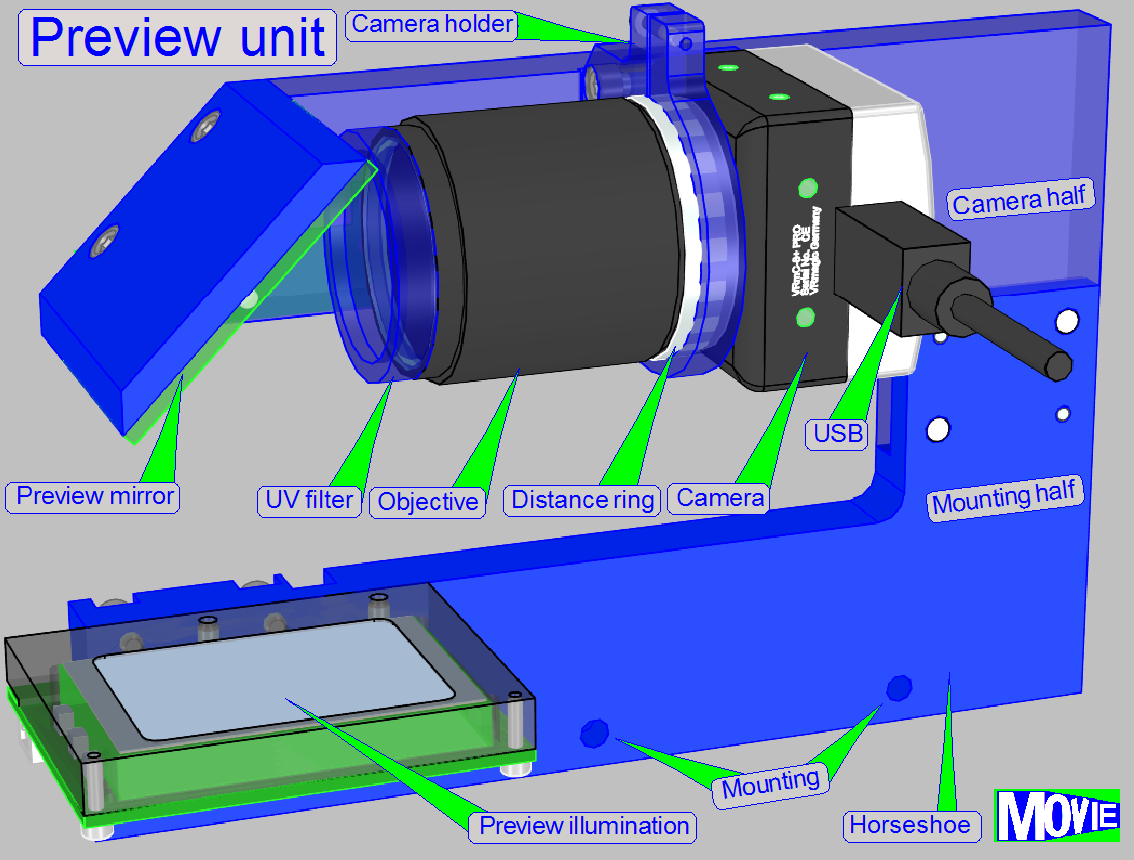
The
horseshoe is the mounting part of the preview unit, and contains the mountings
of following components:
- Objective and
camera holder with fitting plate
- Preview
mirror mounting (can not be removed!)
- Barcode illumination
The entire preview unit is situated on the edge of the
scanner plate, parallel to the magazine unit.
The position is fixed with two fixing pins and hold by
the mounting bolt. To allow an easy remove of the optics, the horseshoe is
divided into a camera half and a mounting half.
Remove the preview unit
· Remove
the mounting bolts and separate the camera half from the mounting half.
Mount the preview unit
· Fit
the fixing pins of the mounting half with the position fixing holes of the
camera half and drive in the half’s mounting bolts.
Preview unit’s horseshoe mounting
The horseshoe
mounting contains two fixing pins to define the position and a threaded hole
for the mounting bolt.
Preview objective
and camera holder
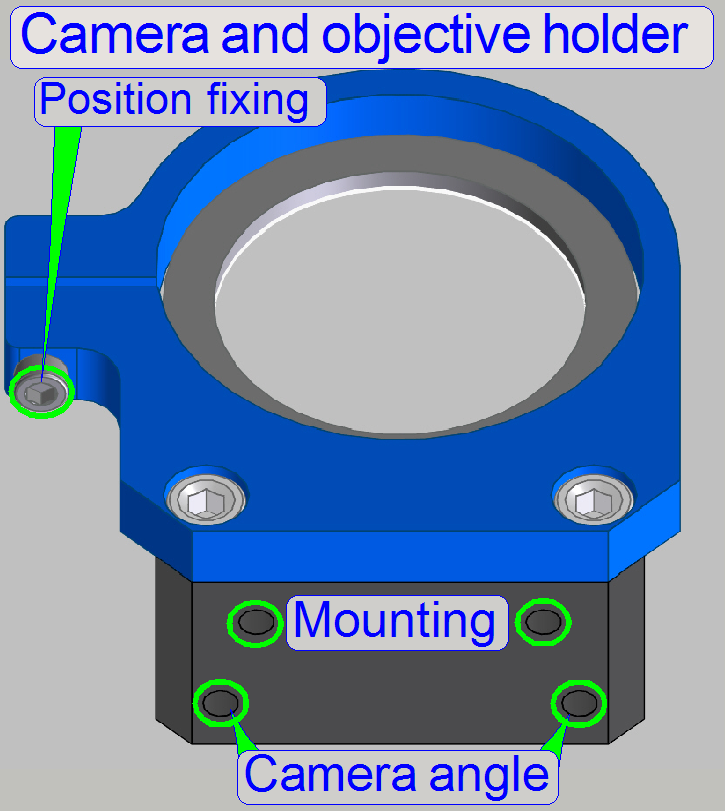
The preview objective and camera holder allows the
adjustment of the preview camera rotation angle in a limited range.
· To
adjust the distance of the objective in relation to the horseshoe, a fitting
plate is used.
To adjust the camera rotation angle:
- Hold the camera on the rear and loosen the position fixing bolt a
little bit until the camera together with the objective becomes barely
rotate-able. Check the tightness of the objective to the camera!
- By loosening one of the “Camera angle” bolts and tightening
carefully the opposite bolt, the rotation angle will be modified.
- If the correct camera rotation angle is found, tighten the
“Position fixing” bolt by pushing the camera to the holder; further
information can be found in the chapter “Adjust the
preview camera rotation angle”.
 Brightfield scan
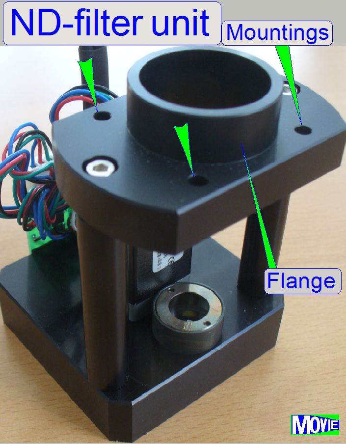
illumination mounting (ND-filter unit)
Brightfield scan
illumination mounting (ND-filter unit)
The flange of the
ND-filter unit is mounted with 4 bolts to the scanner plate.
![]() “Neutral density (ND) filter unit”
“Neutral density (ND) filter unit”
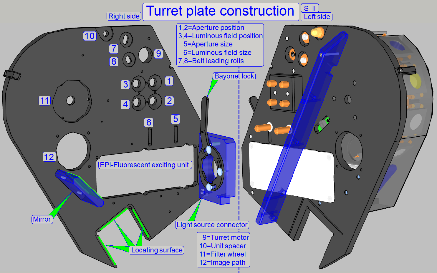
With the locating surface, the correct distance between turret plate and
scanner plate is defined; the turret plate is mounted by the use of clamps and contains the
mountings and fixings for the following main units:
·
EPI-fluorescent
illumination unit