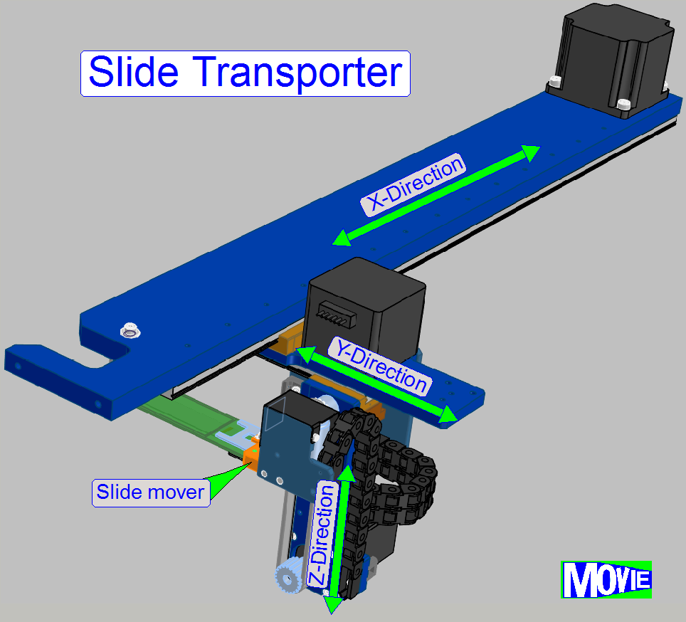
 Slide Transporter;
iSaCS
Slide Transporter;
iSaCS
For
technicians and partly for sales managers!
Introduction
The slide
transporter unit moves the slide into the desired position. Starting from the
origin storage of the slide, the slide is moved to
· Specimen
Preview position
· Staining
position
· Wash
and rinse chamber
· Wiper
position
· Cover
slipping position
· Any
manipulation position
· Slide
tray of the scanner
· From
any position back to the slide’s origin position.
To fulfill this task, the slide mover has to move the
slide along the X-axis, the Y-axis and the Z-axis.
The movement of the slide mover along the axes is
executed by a toothed belt driven mechanics; the belt is driven by a stepper
motor. In relation to a spindle driven solution the accuracy of 1μm is not
required and by using a belt drive, the slide may be moved much faster.
The Slide mover holds the slide with a solenoid
controlled clamp (spoon and fork) on the barcode side, so the slide may be
positioned very precise in the slide bays. The exact position of the slide is
very important during the application procedure of the stain, it has to have
the same position as it had during preview capturing.
Contents
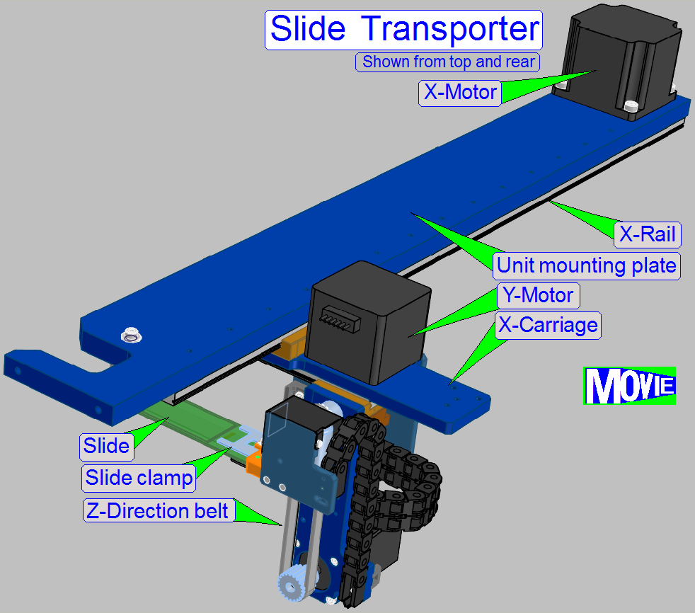
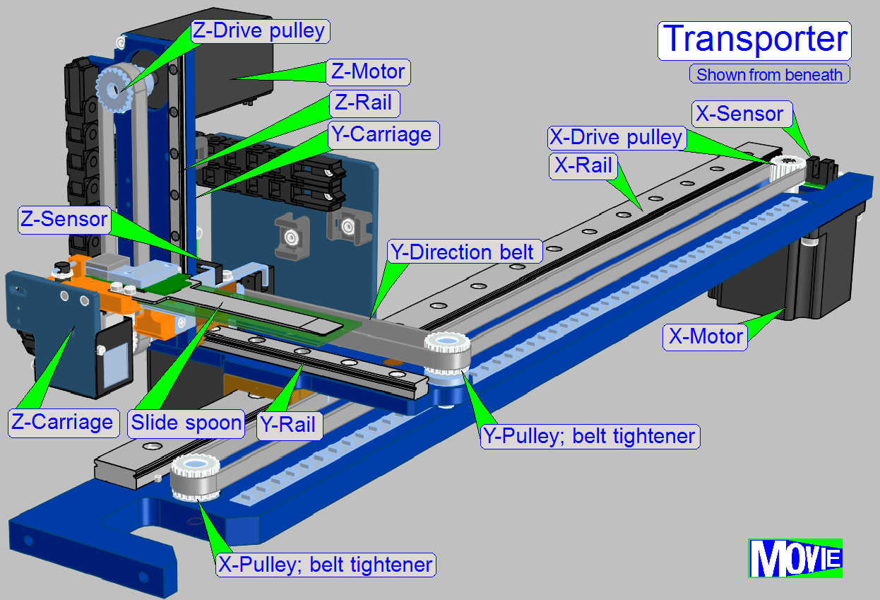
Y-Z-Unit
Z-Unit
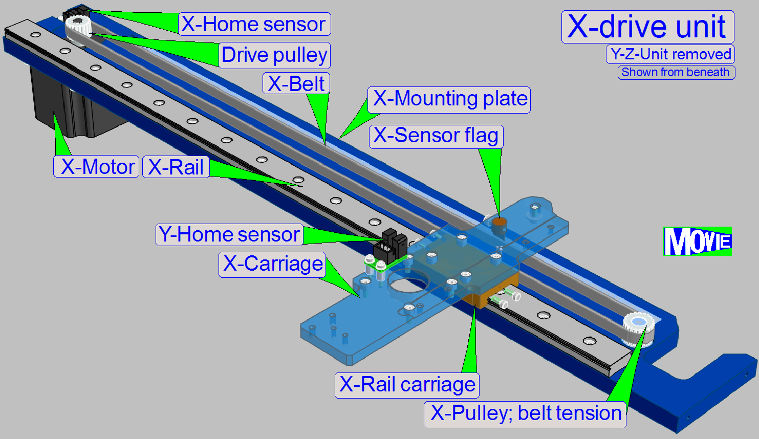 The
statically part of the X-drive unit (and so the entirely construction) is
mounted onto the X-Mounting plate; components are:
The
statically part of the X-drive unit (and so the entirely construction) is
mounted onto the X-Mounting plate; components are:
· X-Motor
· X-rail
· X-Sensor
· Toothed
belt pulley with belt tension adjustment
Dynamically part
· Rotor
axle with toothed drive pulley
· Toothed
belt
· Belt fixing to drive the carriage
· Carriage
(contains the X-sensor flag and the entire Y and Z-unit)
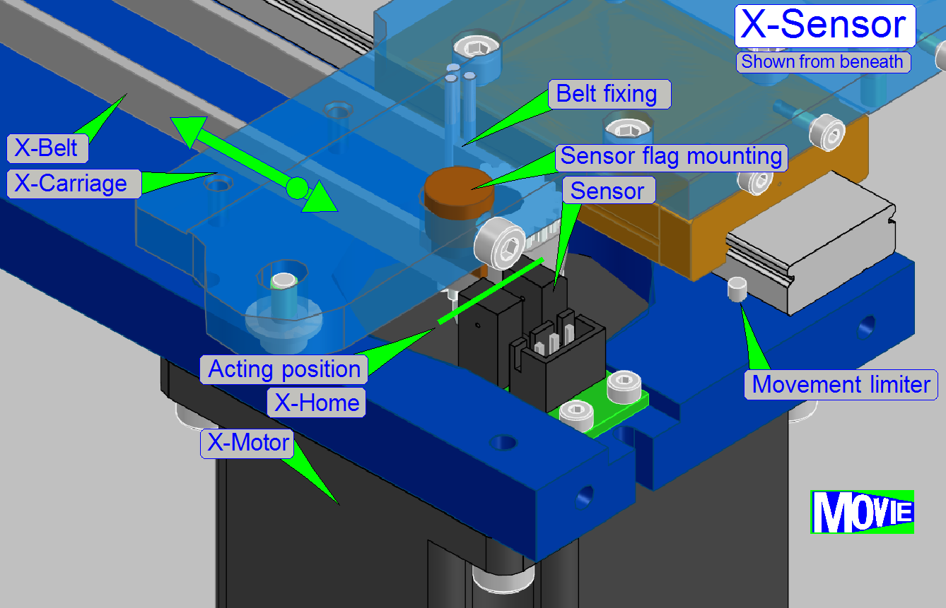 Each
carriage has a Sensor to define the Home position of the entire moveable,
mechanical construction. From the X-Home position steps are counted in positive
or negative direction. The Home position is not the limit of the moveable
construction; the absolute limit is defined by the Movement limiter.
Each
carriage has a Sensor to define the Home position of the entire moveable,
mechanical construction. From the X-Home position steps are counted in positive
or negative direction. The Home position is not the limit of the moveable
construction; the absolute limit is defined by the Movement limiter.
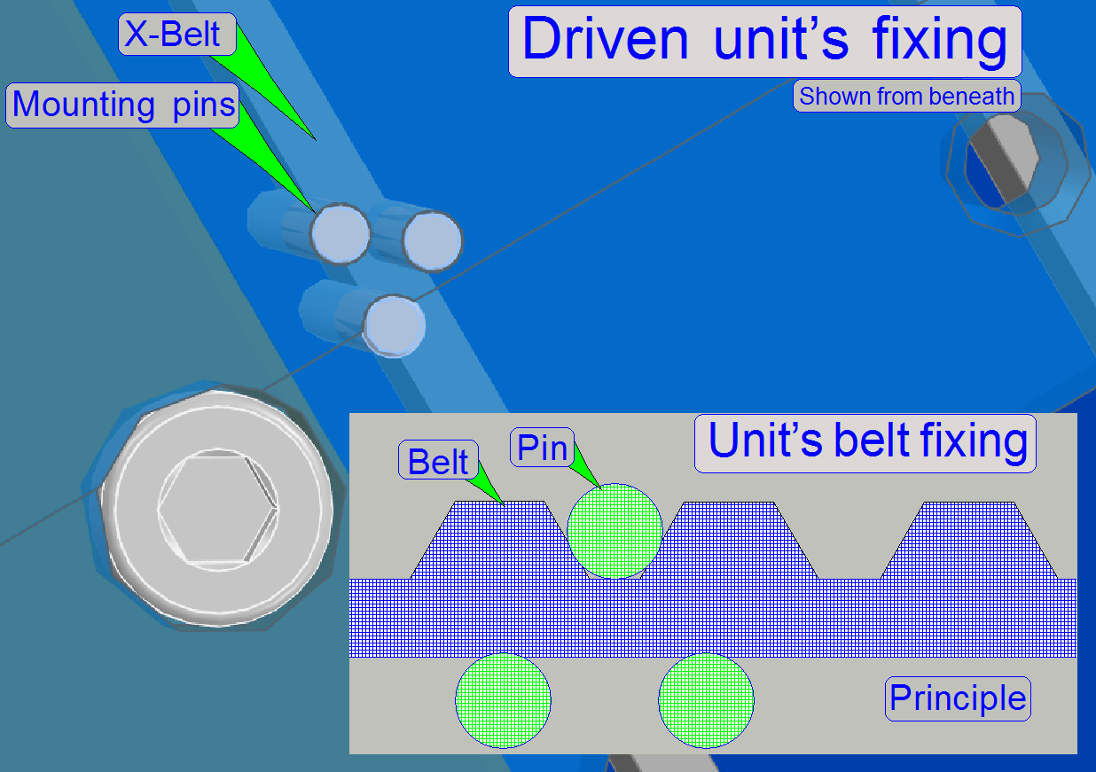 The
belt is shifted into the space, defined by the three pins as shown. With this
solution a slippage free connection between belt and carriage is realized.
The
belt is shifted into the space, defined by the three pins as shown. With this
solution a slippage free connection between belt and carriage is realized.
The dimension and position of the pins to each other and
so the space for the belt was defined so, that the surface of the belt will not
be damaged but by using a little pressure, a movement of the belt in relation
to the pins is impossible.
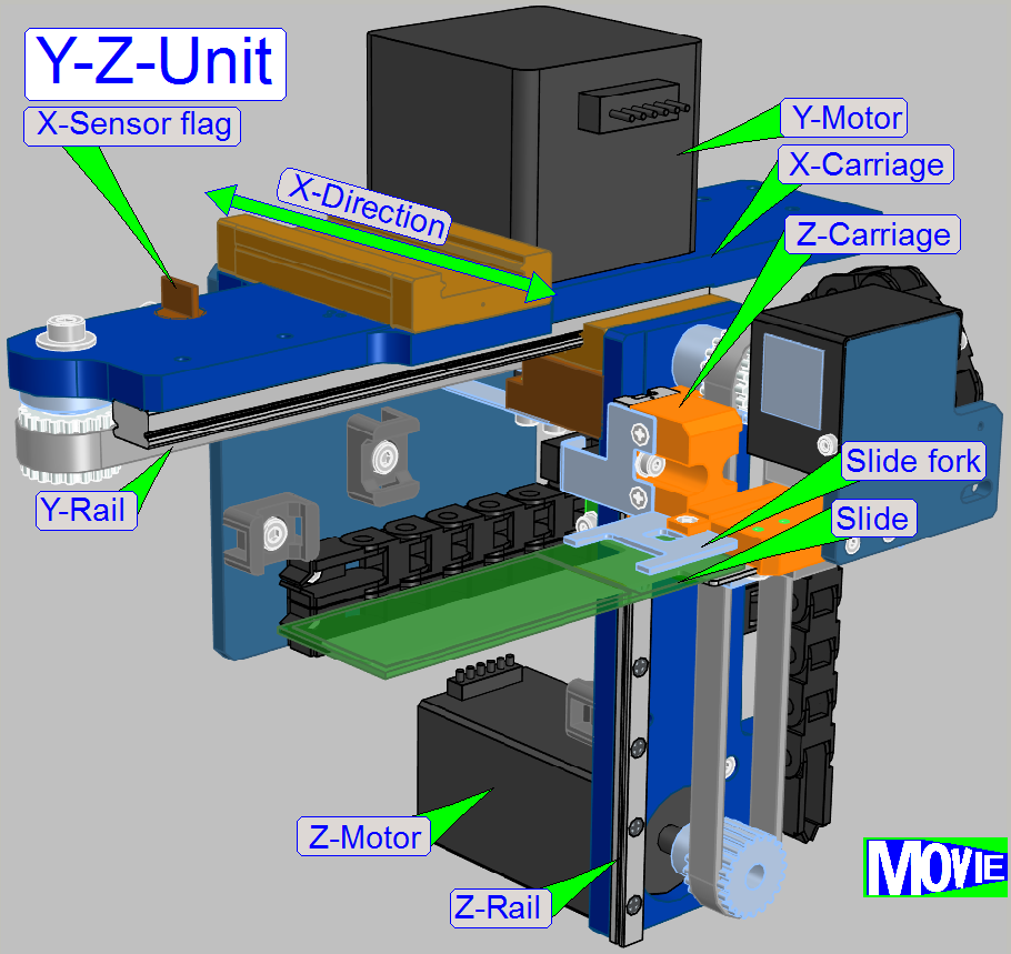 The Y-drive unit
is used to move the Z-unit along the Y-axis.
The Y-drive unit
is used to move the Z-unit along the Y-axis.
· The
moveable part of the Y-drive unit contains the entire Z-unit.
For construction details please refer to the X-drive unit.
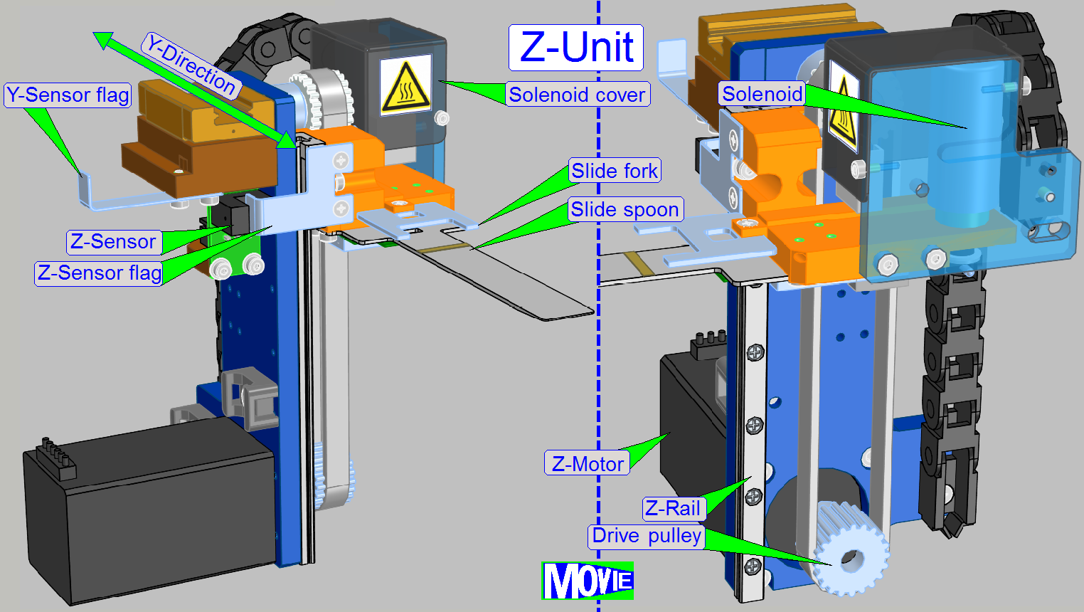 The Z-unit unit
is used to move the Z-carriage in Z-direction.
The Z-unit unit
is used to move the Z-carriage in Z-direction.
· The
Z-carriage is used to move the slide spoon as well as the slide fork along the
Z-axis.
For construction details of the mechanically drive
please refer to the X-drive
unit.
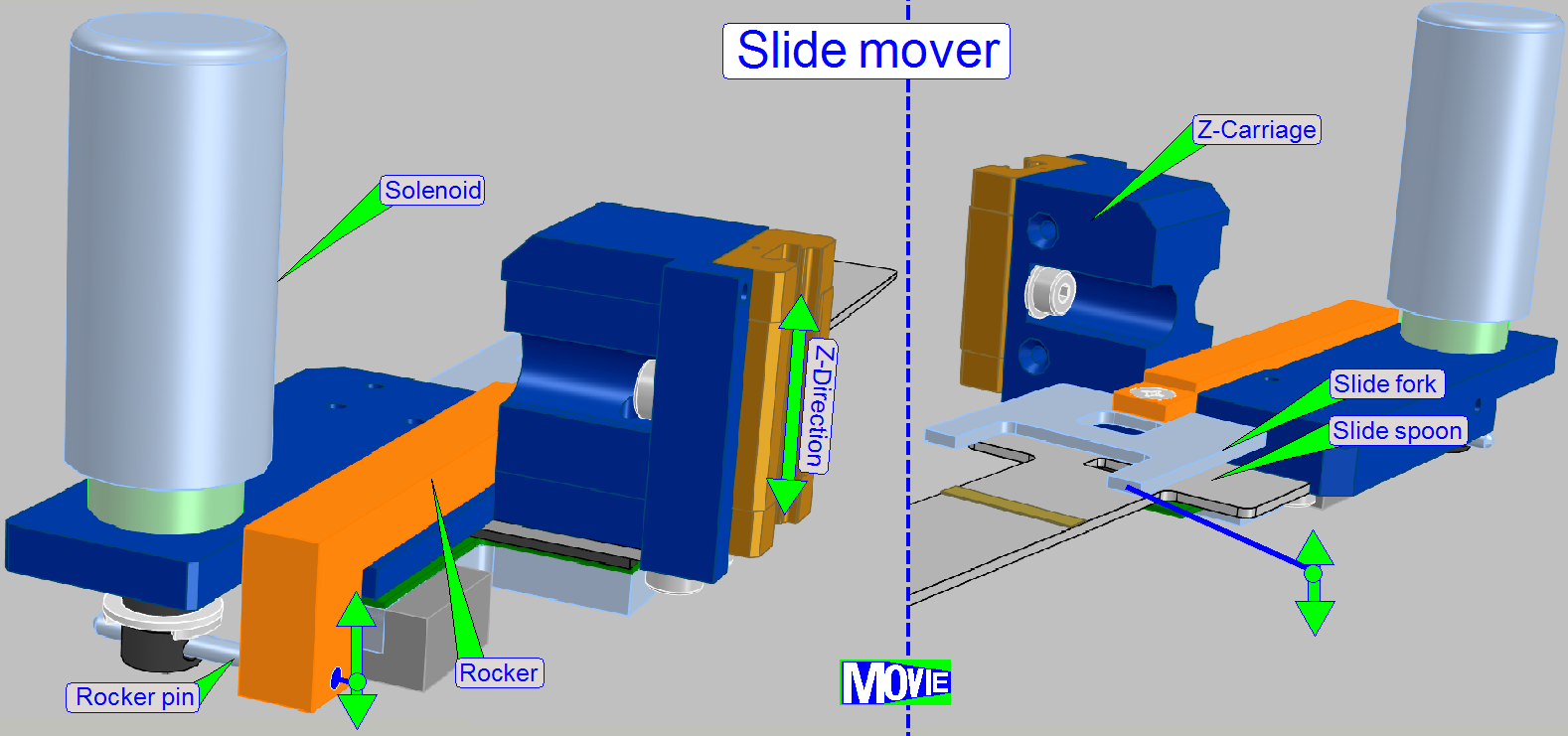 The main
component of the slide mover is the slide spoon with the solenoid controlled
slide fork (clamp).
The main
component of the slide mover is the slide spoon with the solenoid controlled
slide fork (clamp).
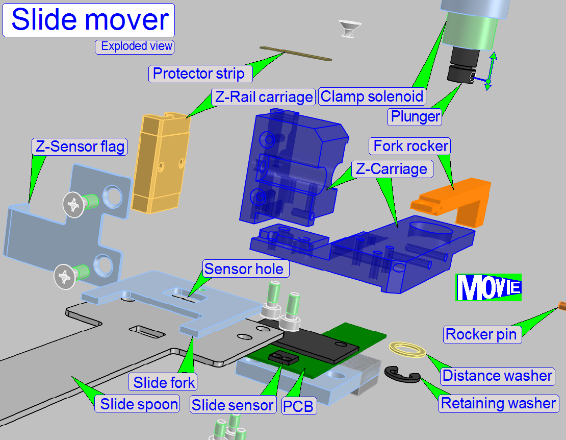 The slide mover
(Slide spoon and slide fork) is mounted on the Z-carriage of the transporter.
The slide spoon is mounted fixed, while the Slide fork is mounted moveable. The
movement of the fork is realized with a solenoid driven rocker.
The slide mover
(Slide spoon and slide fork) is mounted on the Z-carriage of the transporter.
The slide spoon is mounted fixed, while the Slide fork is mounted moveable. The
movement of the fork is realized with a solenoid driven rocker.
The produced force onto the slide is limited by the
Distance washer on the solenoid plunger. By using a protector strip on the
slide spoon not the entire bottom of the slide will contact the spoon.
The force, produced to the slide holding mechanics was
dimensioned so, that the slide may be moved in relation to the spoon and fork
if excessive force is used sideward but during real slide movements of the
slide mover, the slide position will not change.
By using the sideward movement in the slide bay, the
slide can be positioned exactly on the spoon before the slide will be picked up
or released in the slide bay.
This is very important during the staining procedure;
the slide has to have the same position in the staining bay as the slide had in
the preview bay! Only so the start point of the preview will meet the start
point for the staining procedure.
This is very important during applying the stain onto
the specimen, otherwise the start point of the sample will not be matched and
parts of the specimen will be left out during applying the stain and partially
only glass will be filled.
Therefore, the software uses always this algorithm to
center the slide on the spoon, regardless the slide is moved into the staining
bay or not.
Remark
 Because
the slides has tolerances in width (Slide width defined as 25.00mm – 26.00mm)
the center of the slide is not always met, but by using the left-right movement
routine of the spoon, the position of the slide on the spoon is always exact
the same if the slide will be placed or picked up in any slide bay.
Because
the slides has tolerances in width (Slide width defined as 25.00mm – 26.00mm)
the center of the slide is not always met, but by using the left-right movement
routine of the spoon, the position of the slide on the spoon is always exact
the same if the slide will be placed or picked up in any slide bay.
By using always the left-right movement routine of the
spoon, accumulation of placement deviations is eliminated.
· The
spoon is always positioned centered in relation to the standoffs of the slide
before picking up or releasing the slide!
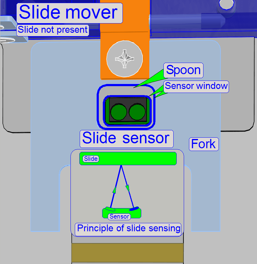 To
optimizing slide mover movements, the software has to know whether a slide is
present or not. For this purpose, the slide in the slide mover is sensed via an
optical sensor.
To
optimizing slide mover movements, the software has to know whether a slide is
present or not. For this purpose, the slide in the slide mover is sensed via an
optical sensor.
· If the
slide is present in the slide mover, the emitted IR light beam will be
reflected return to the sensor by the slide; otherwise the beam will not be
reflected.
To avoid reflecting the beam by the slide fork, the
fork got also a sensor window!