Define hardware limits in Pannoramic scanners
This chapter
summarizes the knowledge and procedures to define hardware limits for stepper
motor driven moveable parts in Pannoramic scanners in global and detailed aspects; used with the PCON,
P250, SCAN,
Contents
Sensor
“Home1” and hardware limits
The file
“MicroscopeConfiguration.ini”
Techniques
to define hardware limits
Units and
their hardware limits
Requirements
· Service
program “SlideScannerService.exe”
· Diverse hex key bolt drivers
(only for some units, where the bumper position can be adjusted)
 The Pannoramic scanner includes hardware units with a stepper
motor driven moveable part.
The Pannoramic scanner includes hardware units with a stepper
motor driven moveable part.
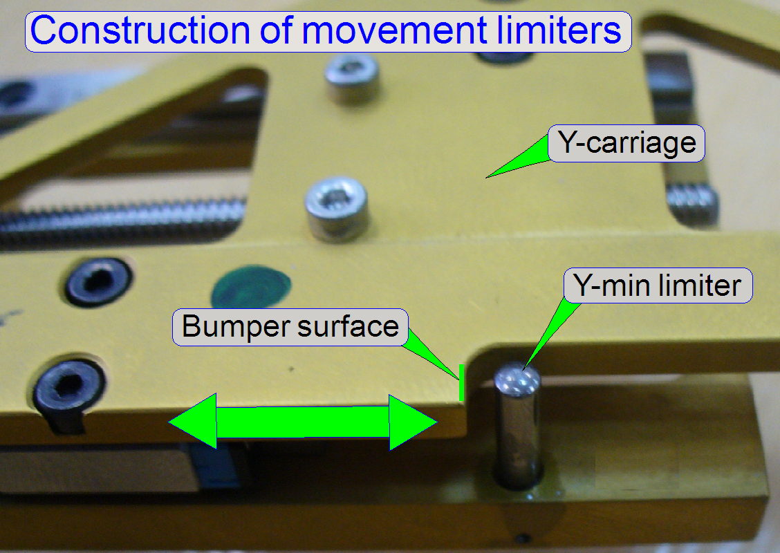
The moveable part, except it can
move endless, needs a start point and an end point as well, so its movement is
limited by the use of a hardware limiter and a bumper surface.
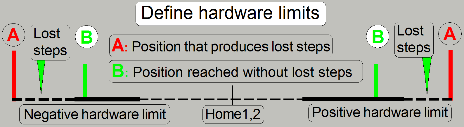
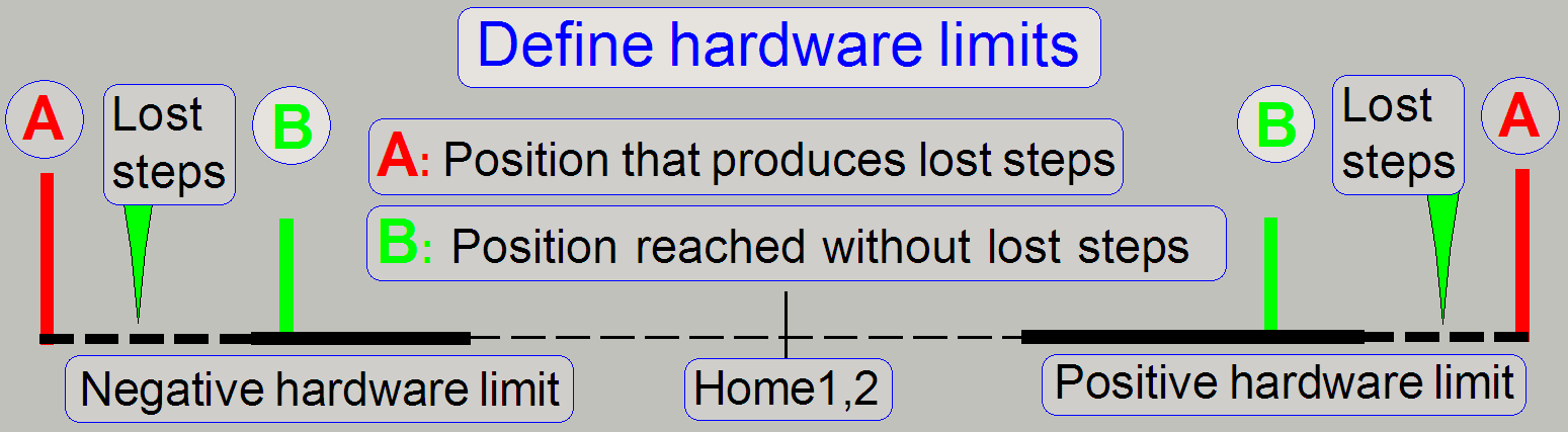
Because lost steps occur, if the
bumper surface bumps against the limiter, the limit positions have to be
defined before the bumper surface reaches the limiter; these are named as lower
and upper hardware limit, negative and positive hardware limit or as hardware
limit “min” and “max”. These defined limit positions are used by the software
to limit the movement of the unit.
Because lost steps are unwanted
during the scan procedure and normal work, the “Hardware limit” position has to be defined before the bumper
surface will reach the hardware limiter; the hardware limit position itself is
a part of the real movement range.
· Usually we can say, the start point of the unit is the
negative limit and the endpoint of the possible movement range is the positive
limit.
Accuracy of the defined
limit
The accuracy of the defined hardware
limit position depends on the unit; in the X-Y-stage unit for example, the
accuracy is 0.1mm (100 steps) during in other units, like the camera changer or
the focus unit, the accuracy of the limit is 10 steps.
This means, the distance of the
bumper surface to the limiter is 0.1mm or less, but the bumper surface never
bumps against the limiter; lost steps must not occur.
· The step number
of the hardware limit is always defined before steps are lost!
· All the used
hardware limit positions for the units are collected in the section
“[HardwareLimits]” of the file “MicroscopeConfiguration.ini”.
On the other side, to find the
correct hardware limit, we are creating lost steps first (with the service
program), and then we reducing the number of steps by the allowed accuracy
(100steps or 10steps) until lost steps do not occur during the movement of the
unit.
· Check the found
hardware limit by moving the unit more (3) times from the position Home1,2 to
the found limit position and return to Home1,2. During these movements, lost
steps should not be experienced (not more then +-2steps).
· Move also the
mechanical drive against the limiter until lost steps are produced. With the service
program, the unit should be able to leave the jammed position if the unit is
moved some 100 steps in direction to Home1,2. If jamming occurred and the unit
can not be moved away from the limiter, the unit is faulty (or adjusted wrong).
During this check please do not use the button “Home1” because the timing and
control of the motor steps is often different between normal move and searching
for Home1.
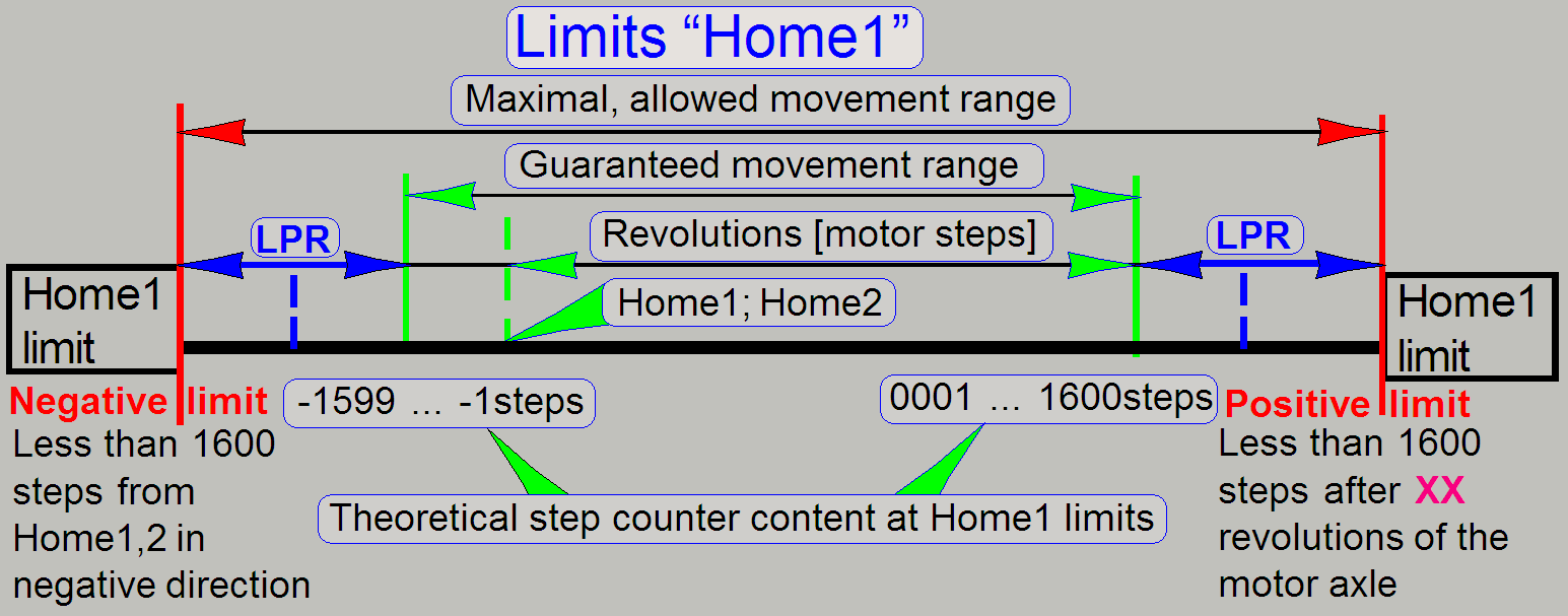
The values, where the limit
positions of the appropriate unit can be found are different from unit to unit
of the same type also, so an interval is defined.
Each unit of the same type has its
limit “min” and “max” in the defined range (the limiter position range, LPR),
outside the guaranteed movement range.
Maximal movement range
The maximal movement range is
defined by the behavior of the sensor “Home
· If the moving part of the unit can be moved behind the
specified value of the maximal movement range (the limit “Home1”), the unit is
faulty.
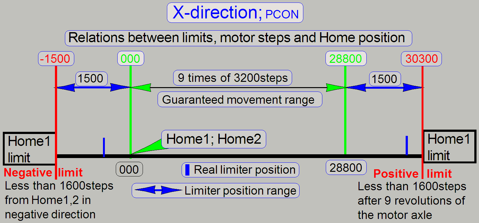
Guaranteed
movement range
· 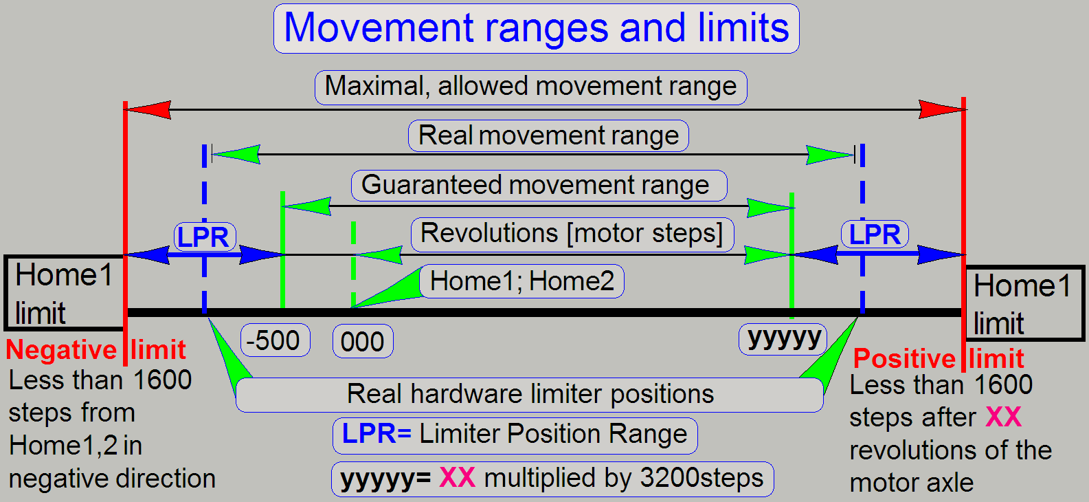 The guaranteed movement range is defined by the
requirements of the moveable unit to fulfill its task; it may be 1revolution,
several 10 revolutions until over 200 revolutions of the motor axle.
The guaranteed movement range is defined by the
requirements of the moveable unit to fulfill its task; it may be 1revolution,
several 10 revolutions until over 200 revolutions of the motor axle.
· The guaranteed movement range is defined by the number
of revolutions of the stepper motor axle.
· In exceptions, it is prolonged by some 100 steps in
any direction by shortening the limiter position range (LPR).
· In exceptions the upper limit may be shortened if
collision of components would occur.
See also: P250 hardware limit
Y-max and SCAN
hardware limit Y-max
Position Home1,2
The home position of the entire
mechanical drive, the start position for counting motor steps, is defined
inside the guaranteed movement range. Starting from this position, the rotor
steps are counted in positive or negative direction.
Real movement range
· The real movement range is always larger then the
guaranteed movement range, it is limited by the found hardware limiter
positions; before the bumper surface contacts the limiter; except the camera
changer unit and the focus unit.
· The absolute value of the negative limit of the real
movement range is less than or equal to the negative limit of the maximal
movement range (the limit “Home1”).
· The positive limit of the real movement range is less
than or equal to the positive limit of the maximal movement range (the limit
“Home1”).
 The hardware limiters for the positive and the
negative limit of the unit are physically found in this range.
The hardware limiters for the positive and the
negative limit of the unit are physically found in this range.
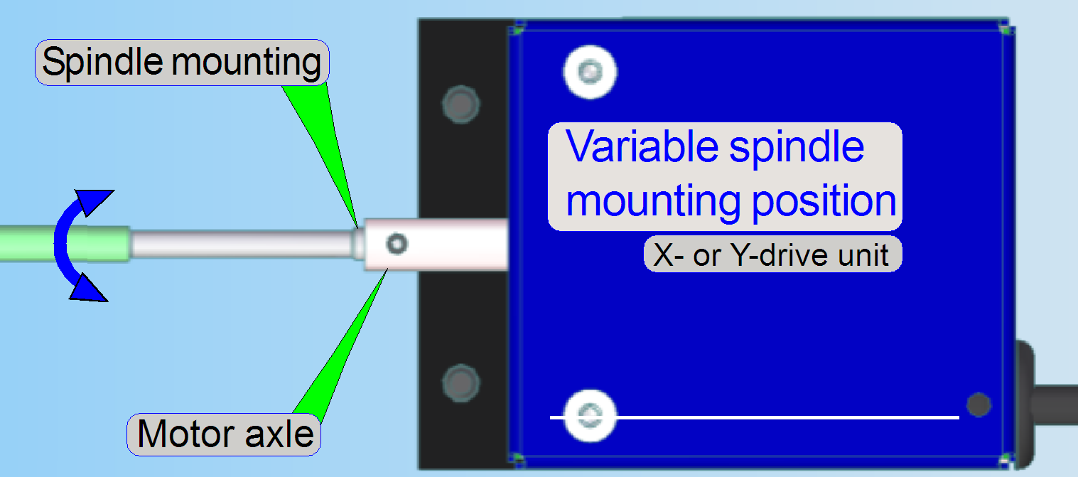
The physical position of the
limiters and the bumper surfaces are always exactly on the same place in the
unit, therefore, if the negative limit is found correctly, the positive limit
will always fulfill the requirement of the limit “Home1”; but because the
mounting position of the spindle in relation to the rotor axle is variable (X-
and Y-drive unit) and the found thread starting position of the transport nut
is defined with an accuracy of 800steps, the real hardware limit value may be
anywhere in this range.
· The found hardware limit values define the real
movement range.
See also: “Exchange
the Y-drive of the X-Y-stage unit”
and “Before we can mount the
drive unit”
In the focus unit
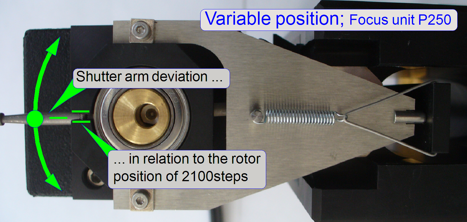 In the focus unit the hardware limit values depending
highly on the found ex-center position on the motor axle.
In the focus unit the hardware limit values depending
highly on the found ex-center position on the motor axle.
See also: in the P250: “Adjust the ex-center position”
SCAN,
· In the SCAN, the
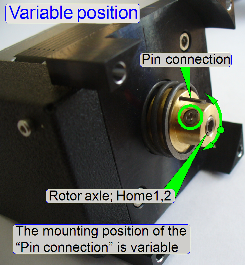 In the camera changer unit the “Variable position” of
the guaranteed movement range depends on the found clutch mounting position on
the motor axle; so the pin connection may be in different positions in relation
to the home position of the rotor. Therefore, the home position Home1,2 will be
only in exceptions in the center of the guaranteed movement range.
In the camera changer unit the “Variable position” of
the guaranteed movement range depends on the found clutch mounting position on
the motor axle; so the pin connection may be in different positions in relation
to the home position of the rotor. Therefore, the home position Home1,2 will be
only in exceptions in the center of the guaranteed movement range.
Sensor “Home1” and hardware limits
 This chapter describes the role of the sensor “Home1”
during the definition of the hardware limits.
This chapter describes the role of the sensor “Home1”
during the definition of the hardware limits.
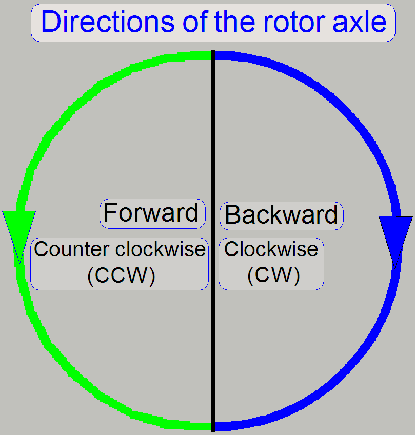
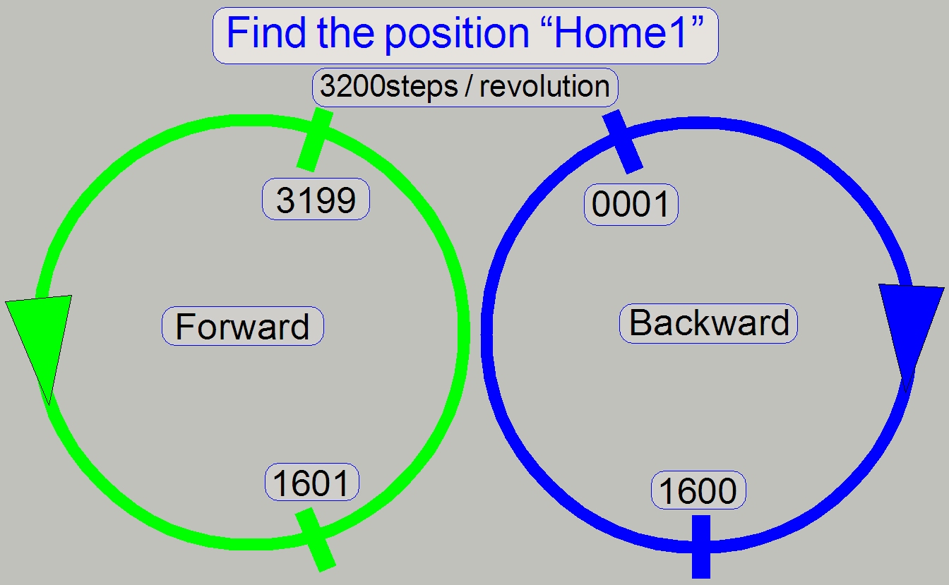
· If the mechanical drive is moved in direction to the
“max” (positive) limit, the rotor of the stepper motor rotates forward (CCW);
the step number of the step counter will be increased.
· If the mechanical drive is moved in direction to the
“min” (negative) limit, the rotor of the stepper motor rotates backward (CW);
the step number of the step counter will be decreased.
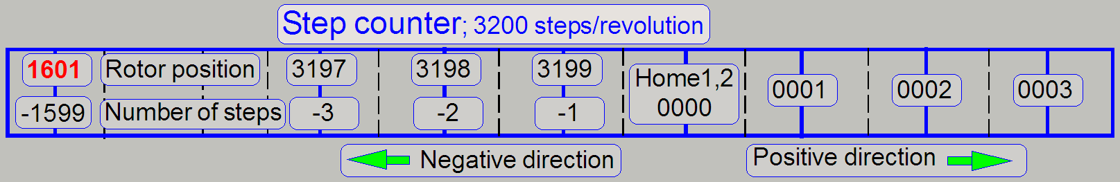
Important remark
The hardware limits are always
defined as a number of steps, done in the positive or negative direction,
counted from Home1,2.
During stepping in positive
direction, the “Rotor position” is identical with the “Number of steps” gone!
· If we are doing steps in negative direction, the
“Number of steps” gone is different from the “Rotor position”!
· The service program shows always the step counter
content, not the rotor position
· The value of the appropriate hardware limit is always
the “Number of steps”; in “our” step counter example above the lowest value would be -1599! And not
1601!
Home sensor “Home1”
 The implementation of the sensor “Home1” defines the
main restriction in question of all the hardware limits.
The implementation of the sensor “Home1” defines the
main restriction in question of all the hardware limits.
Depending on the actual step number of
the step counter, the rotor rotates forward (CCW) or backward (CW) respectively
to find the position “Home1”.
· If the step number of the step counter is in the range
from +0001 to +1600 (or a multiple number of +3200steps) and the command
“Home1” is issued, the rotor is moved backward (CW) to find the position
“Home1”.
· If the step number of the step counter is in the range
from -1 (rotor position 3199) to -1599
(rotor position 1601) (or a multiple number of +3200steps) and the
command “Home1” is issued, the rotor is moved forward (CCW) to find the
position “Home1”.
· If the step number of the step counter stays in the
position “
· Because we allowing a maximal tolerance of +-2steps in
the found home position, and the position 1600steps of the rotor is critical
for the sensor “Home
Remark
The explanation above is true if we
assume that the revolution of the rotor is done in 3200steps; the position of
1600steps defines exact a half revolution. If the revolution is done in
6400steps, the number of steps for a half revolution is also twice, 3200steps.
The sensor “Home1” works always with a half revolution!
See also: “Sensors Home1,2”; and “Sensors”.
Negative limit
 The rotor rotates in backward direction (CW), seen from
the state “Home1,2” (the steps are counted in backward direction also; the step
number in the step counter will be decreased) until the rotor position “
The rotor rotates in backward direction (CW), seen from
the state “Home1,2” (the steps are counted in backward direction also; the step
number in the step counter will be decreased) until the rotor position “
If we would allow more steps to go
in backward direction, the construction would overstep the border of the rotor
position of “
· The absolute negative limit (defined by the limiter) is
always less than 1600steps in negative direction, counted from Home1,2 (lost
steps have to be generated before the
rotor position of 1600steps is reached); otherwise the unit is faulty (or
adjusted wrong; please refer to the chapter “Limiter position range”)..
Positive limit
The mechanics moves in direction to
the positive limit, (the rotor moves forward, CCW).
The number of steps in the step
counter will be increased and, if the guaranteed movement range is passed, the
sensor “Home1” defines also the possible number of steps to go; this number is
also less than 1600steps.
The rotor rotates in forward
direction, seen from the state “Home1,2” until the step number “
If we would allow more steps to go
in forward direction, we would overstep the border of 1600 steps (the rotor
position would be higher than 1600 steps) and, if we issuing the command
“Home1” the rotor would move forward to find the position “Home1”, mechanical
jamming of the construction would occur; the moving part would be moved against
the limiter and lost steps occur.
· The absolute positive limit (defined by the sensor
“Home1”) is always less than 1600steps in positive direction after the
guaranteed movement range is passed, counted from Home1,2 (lost steps have to
be generated before the rotor position
of 1600steps is reached); otherwise the unit is faulty (or adjusted wrong;
please refer to the chapter “Limiter
position range”).
Remark
Because we are allowing a tolerance
of 2steps, the hardware limit in the position 1600steps of the sensor “Home1”
is critical and should never be used. In other words, the found hardware limit
position should be always clearly less then 1600steps.
If the resolution of the motor is
6400 steps, the border value of 1600 steps is also changed to the value of
3200steps. In other words, we using always exact a half revolution of the rotor
to define the limit of the sensor “Home1”.
See also: “Sensors Home1,2”; and “Sensors”.
File
“MicroscopeConfiguration.ini”
· Please make a security backup of the file “Microscope
Configuration.ini” before modifying values!
The file “MicroscopeConfiguration.ini”
will be found in the folder:
 In the
software version 1.14 (Windows XP): C:\DocumentsAndSettings\AllUsers\ApplicationData\3DHISTECH\SlideScanner\
In the
software version 1.14 (Windows XP): C:\DocumentsAndSettings\AllUsers\ApplicationData\3DHISTECH\SlideScanner\
In the software version 1.15 or
higher (Windows 7): C:\ProgramData\3DHISTECH\SlideScanner\
In earlier
software versions: The file
“MicroscopeConfiguration.ini” or “Config.ini” is situated in the same folder as
the scan program; the filename of the scan program was “Mscan.exe”. Please use
the file search option of Windows and search for the file
MicroscopeConfiguration.ini or “Config.ini”.
See also: SlideScannerSercie.exe and Paths and
locations
·
To edit the
parameter values of the file “MicroscopeConfiguration.ini” the program
“WordPad” or “Notepad” should be used.
·
Save the file
“MicroscopeConfiguration.ini” without any formatting information, as a
*.txt-type file (text only)!
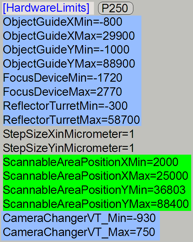
Section [HardwareLimits]
All the used hardware limit
positions for the units are collected in the section “HardwareLimits” of the
file “MicroscopeConfiguration.ini”.
· Depending on the scanner type and the configuration,
not all the parameter values are used.
· Other sections of the file
“MicroscopeConfiguration.ini” may also be affected by the found hardware limit;
please see the appropriate unit.
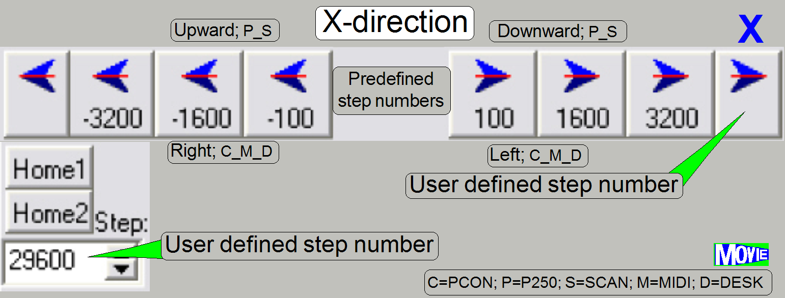
Techniques to define hardware limits
Using lost steps
 Start the service program and set the appropriate unit
to its home position.
Start the service program and set the appropriate unit
to its home position.
To find the hardware limit of the unit
in question, we always producing lost steps first, then we decreasing the
absolute number of steps to go by the number of steps with the limit accuracy
until lost steps do not occur.
· The first number of steps that do not produce lost
steps is used as hardware limit.
· Always check and define the negative limit first, then
the positive limit.
· Limit adjustments are always done with the negative
limit position!
1.
Set the
appropriate unit to its Home1,2 position.
2.
Start with a step
number outside the guaranteed movement range.
3.
Move the unit
to the start position and go backward the same number of steps.
4.
Press Home1
only.
5.
If there are not more than 2 steps difference to
Home1, increase the number of steps by the accuracy of the limit (100 or
10steps) and repeat from step
6.
If there are more than 2 steps difference to Home1,
decrease the number of steps by the accuracy of the limit (100 or 10steps) and
repeat from step
Remark
· The starting number of steps to find the negative
limit is outside of the guaranteed movement range, I prefer the use of
1300steps (X- or Y-stage).
· The starting number of steps to find the positive limit
is also outside of the guaranteed movement range, it should be higher by some
100steps.
· In all cases, even if the found limit number is in the
near of the maximal movement range, the correct working
of the home sensor “Home1” should be checked painstakingly.
Example to find the negative
limit in -X-direction
1.
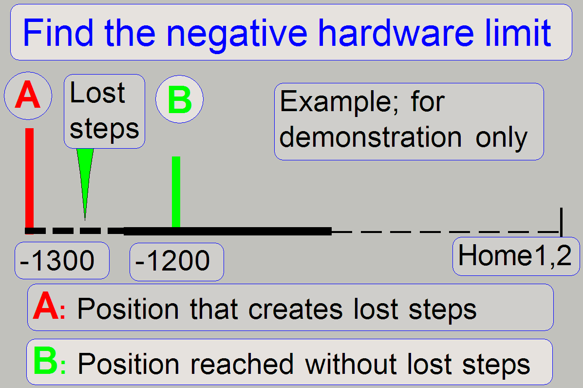 With the service
program set the Y-carriage to Home1,2.
With the service
program set the Y-carriage to Home1,2.
2.
Set the X-carriage to Home1,2.
3.
With the service program go forward to the X-motor
position -1300 steps.
4.
Go backward +1300 steps.
5.
Press Home1 (only). There should be not more than +-2
steps difference to Home1. If there are more steps lost, decrease the actual
absolute number of steps by 100 and repeat from step
6.
If there are not more than 2 steps difference to
Home1, increase the number of steps by 100 and repeat from step
7.
The negative limit is found correctly if the motor
movement has no steps lost and the actual absolute number of steps, increased
by 100 would produce lost steps.
8.
Update the value of the parameter “ObjectGuideXMin” in the file “MicroscopeConfiguration.ini” section [HardwareLimits] with the found
number of the actual steps and save the file.
Remark
The found negative limit can differ by more 100steps from unit to unit. The
reason is the spindle fixing position on the motor axle and the found thread
starting position of the spindle in relation to the transport nut.
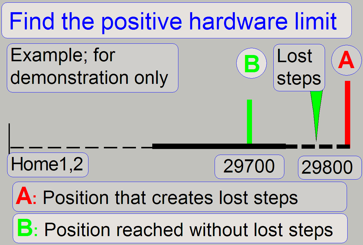
Example to find the positive limit in +X-direction
9.
 With the service program set
the X-carriage unit to Home1,2.
With the service program set
the X-carriage unit to Home1,2.
10.
Go forward to the X-motor position +29700 steps.
11.
Go backward 29700 steps.
12.
Press Home1 (only). There should be not more than +-2
steps difference to Home1. If there are more steps lost, decrease the actual
number of steps by 100 and repeat from step
13.
If there are not more than 2 steps difference to
Home1, increase the number of steps by 100 and repeat from step
14.
The positive limit is found correctly if the motor
movement has no steps lost (max. 2 steps) and the actual number of steps,
increased by 100 would produce lost steps.
15.
Update the value of the parameter “ObjectGuideXMax” in the file “MicroscopeConfiguration.ini” section [HardwareLimits] with the found
value and save the file.
16.
 Check the found
limits by using the number of steps, used as parameter value in the file “MicroscopeConfiguration.ini” section [HardwareLimits]. Lost steps have not
to occur.
Check the found
limits by using the number of steps, used as parameter value in the file “MicroscopeConfiguration.ini” section [HardwareLimits]. Lost steps have not
to occur.
Remark
The found positive limit can differ by more 100steps from unit to unit.
The reason is the spindle fixing position on the motor axle and the found
thread starting position of the spindle in relation to the transport nut.
Units and their hardware limits
X-direction; PCON
 Parameters: [HardwareLimits]
“ObjectGuideXMin”; “ObjectGuideXMax”
Parameters: [HardwareLimits]
“ObjectGuideXMin”; “ObjectGuideXMax”
· The accuracy= 100steps (0.1mm)
Negative limit
-1500steps ≤ “ObjectGuideXMin” < Home1,2
Positive limit
28800steps < “ObjectGuideXMax” ≤ 30300
Other related or affected sections and parameters: none
See also: “X-Y-stage unit” and “Find the
hardware limits”
Y-direction; PCON
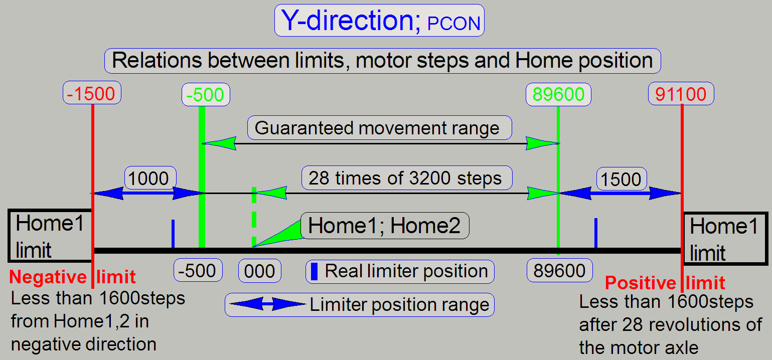 Parameters: [HardwareLimits]
“ObjectGuideYMin”; “ObjectGuideYMax”
Parameters: [HardwareLimits]
“ObjectGuideYMin”; “ObjectGuideYMax”
· The accuracy= 100steps (0.1mm)
Negative limit
-1500steps ≤
“ObjectGuideYMin” < -500steps
Positive limit
89600steps <
“ObjectGuideYMax” ≤ 91100steps
Other related or affected sections and parameters: none
See also: “X-Y-stage unit” and “Find the
hardware limits”
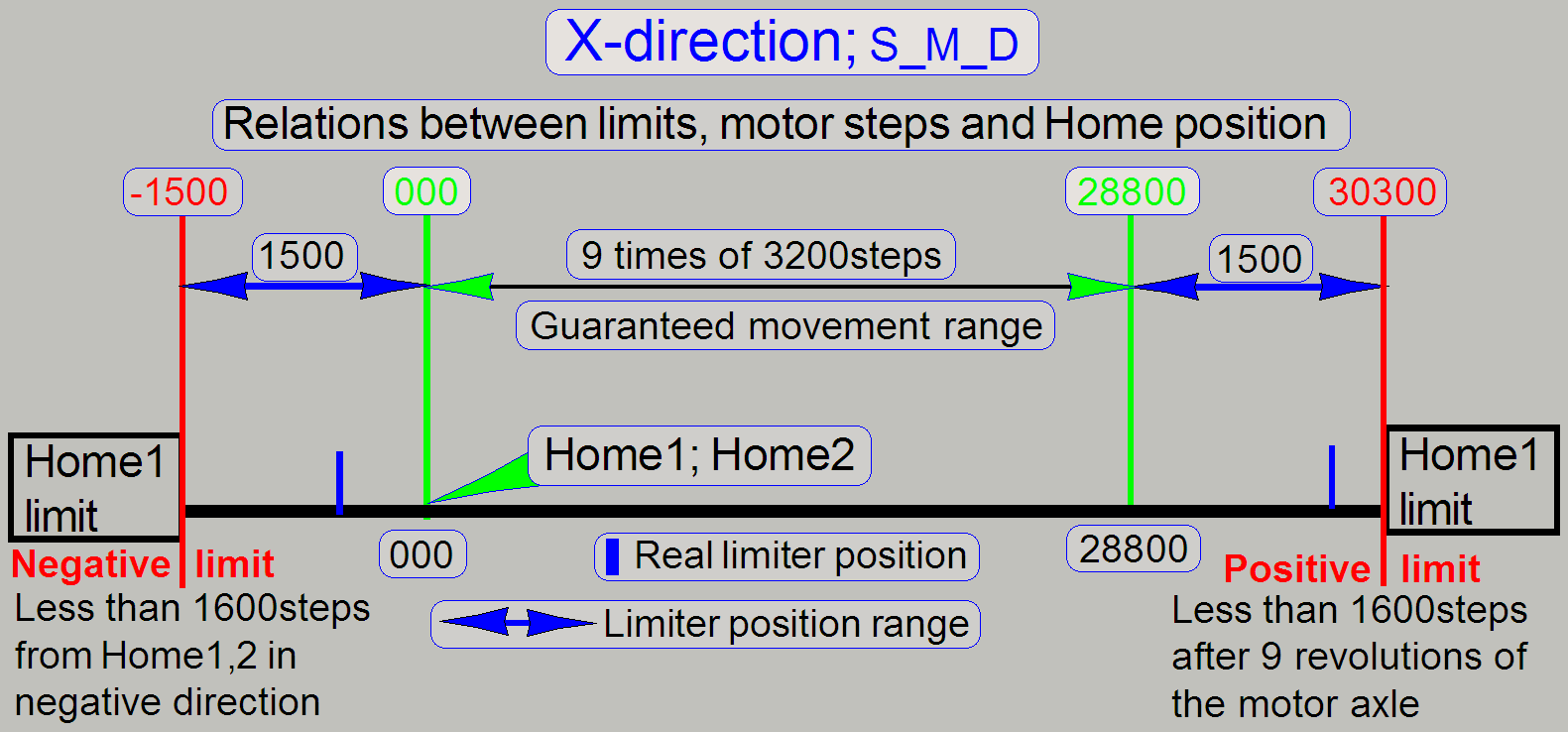
X-direction; P250
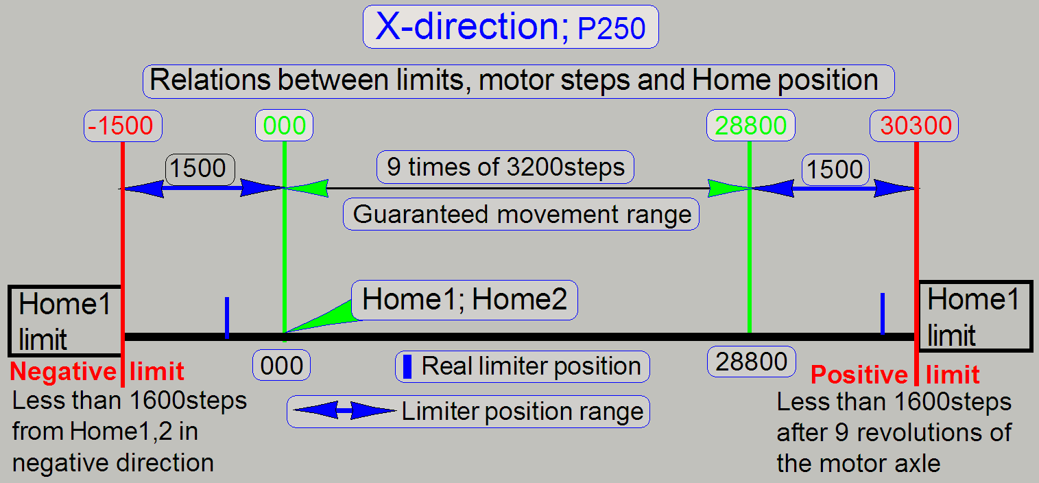 Parameters: [HardwareLimits]
“ObjectGuideXMin”; “ObjectGuideXMax”
Parameters: [HardwareLimits]
“ObjectGuideXMin”; “ObjectGuideXMax”
· The accuracy= 100steps (0.1mm)
Negative limit
-1500steps ≤
“ObjectGuideXMin” < Home1,2
Positive limit
28800steps <
“ObjectGuideXMax” ≤ 30300
Other related or affected sections and parameters: none
See also: “X-Y-stage
unit” and “Find
the hardware limits”
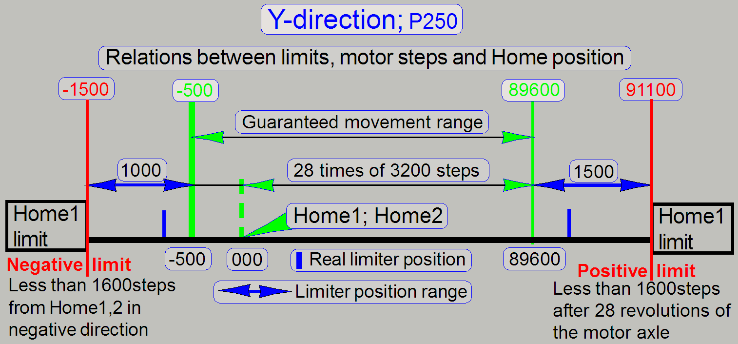 Parameters: [HardwareLimits]
“ObjectGuideYMin”; “ObjectGuideYMax”
Parameters: [HardwareLimits]
“ObjectGuideYMin”; “ObjectGuideYMax”
· The accuracy= 100steps (0.1mm)
Negative limit
-1500steps ≤
“ObjectGuideYMin” < -500steps
Positive limit
89600steps <
“ObjectGuideYMax” ≤ 91100steps
Other related or affected sections and parameters: none
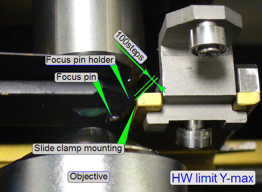 To
avoid collision of the slide clamp with the focus pin holder, the possible
upper limit of the Y-carriage can not be used as hardware limit!
To
avoid collision of the slide clamp with the focus pin holder, the possible
upper limit of the Y-carriage can not be used as hardware limit!
·
Move the Y-carriage in direction to
the limit “Y-max” until a gap of 0.1mm (= 100 steps) exists between the focus
pin holder and the slide clamp (mounting)!
The value is found in the near of
89000 steps
Other related or affected sections and parameters: none
See also: “X-Y-stage
unit” and “Find
the hardware limits”
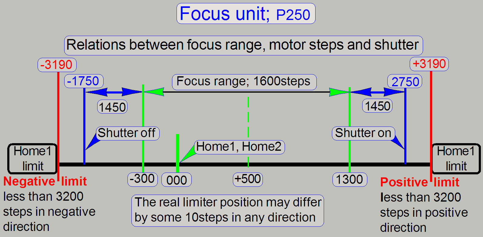 Parameters: [HardwareLimits] “FocusDeviceMin”; “FocusDeviceMax”
· The accuracy= 10steps
· The hardware limit’s values depending highly on the
found ex-center position on the motor axle.
Negative limit
-3190steps ≤ “FocusDeviceMin” < -300steps
Other related or affected sections and parameters:
[Focus]; CondenserCoverOff
Positive limit
1300steps < “FocusDeviceMax” ≤ 3190steps
Other related or affected sections and parameters:
[Focus]; CondenserCoverOn
See also: “Adjust the ex-center
position” and “Find the hardware
limits for the focus unit”
Remarks
The focus motor has a resolution of 6400steps / revolution; so the limit
of “Home1” is defined by 3200steps.
The hardware limit is defined by the shutter wire and the shutter arm.
The real limit position depends on the adjusted ex-center position and
may vary by some 10steps.
Camera changer
unit; P250
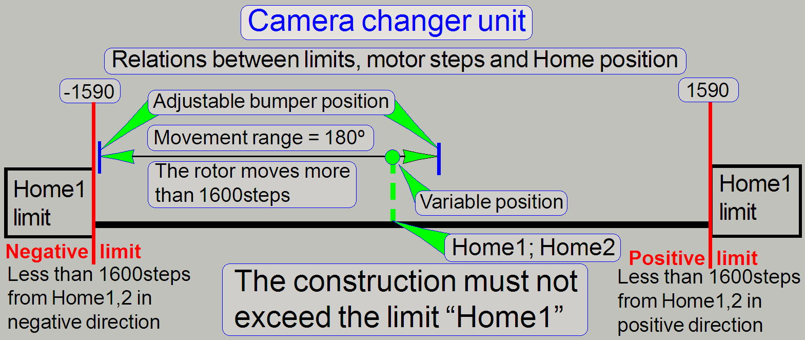 Parameters: [HardwareLimits] “CameraChangerVT_Min”; “CameraChangerVT_Max”
· The accuracy = 10steps
· The hardware limit’s values depending highly on the
found clutch-pin position on the motor axle; see “Variable position”.
Negative limit
-1590steps ≤ “CameraChangerVT_Min”;
See also: “Movement limiters” and “Find the
hardware limits”
Other related or affected sections and parameters:
[CameraChangerVT]; Position1=
See also: “Define the mirror disc working position”
Positive limit
“CameraChangerVT_Max” ≤ 1590steps;
See also: “Movement limiters” and “Find the hardware limits”

Other related or affected sections and parameters:
[CameraChangerVT]; Position2=
See also: “Define the mirror disc working position”
Remarks
The “Variable position”
means, the position Home1,2 is only in exceptions in the center of the
guaranteed movement range.
On the other side, the construction must be fit always between
the limits Home1!
·
The positions “C”, the last position without lost
steps, must not exceed the limits “Home1”; otherwise, the adjustment is faulty!
Reflector turret
unit; P250 (belt driven)
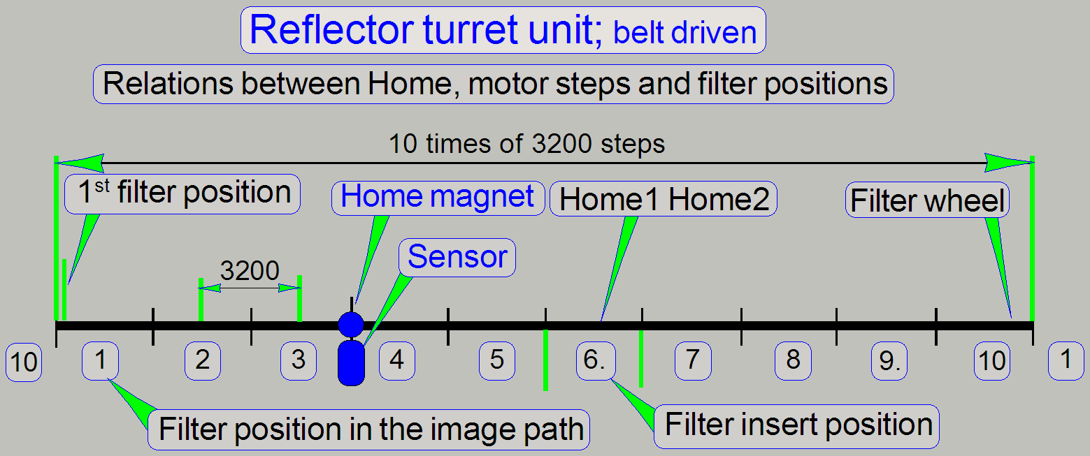 Parameters: none
See also: “Principle of the belt drive”
Other related or affected sections and parameters:
[ReflectorTurret];
StartingMotorPosition= see: “Find the
first filter position”
Remark
Parameters: [HardwareLimits] “ReflectorTurretMin”; “ReflectorTurretMax” are not
interpreted if the “ReflectorTurretType”
in the section [Microscope] is set to “RT_3DH_10Pos_Belt”
ReflectorTurretType=
RT_3DH_10Pos_Belt; see: “Configure the belt driven reflector turret unit”
See also: “Find the Home position of the filter wheel” and
“Check
or adjust the external sensor acting range”
X-stage unit; SCAN,
Parameters: [HardwareLimits] “ObjectGuideXMin”; “ObjectGuideXMax”
·  The accuracy= 100steps (0.1mm)
Negative limit
-1500steps ≤ “ObjectGuideXMin” < Home1,2
Positive limit
28800steps < “ObjectGuideXMax” ≤ 30300
Other related or affected sections and parameters: none
See also: “X-Y-stage
unit” and “Find the
hardware limits”
Y-stage unit; SCAN,
Parameters: [HardwareLimits] “ObjectGuideYMin”; “ObjectGuideYMax”
· 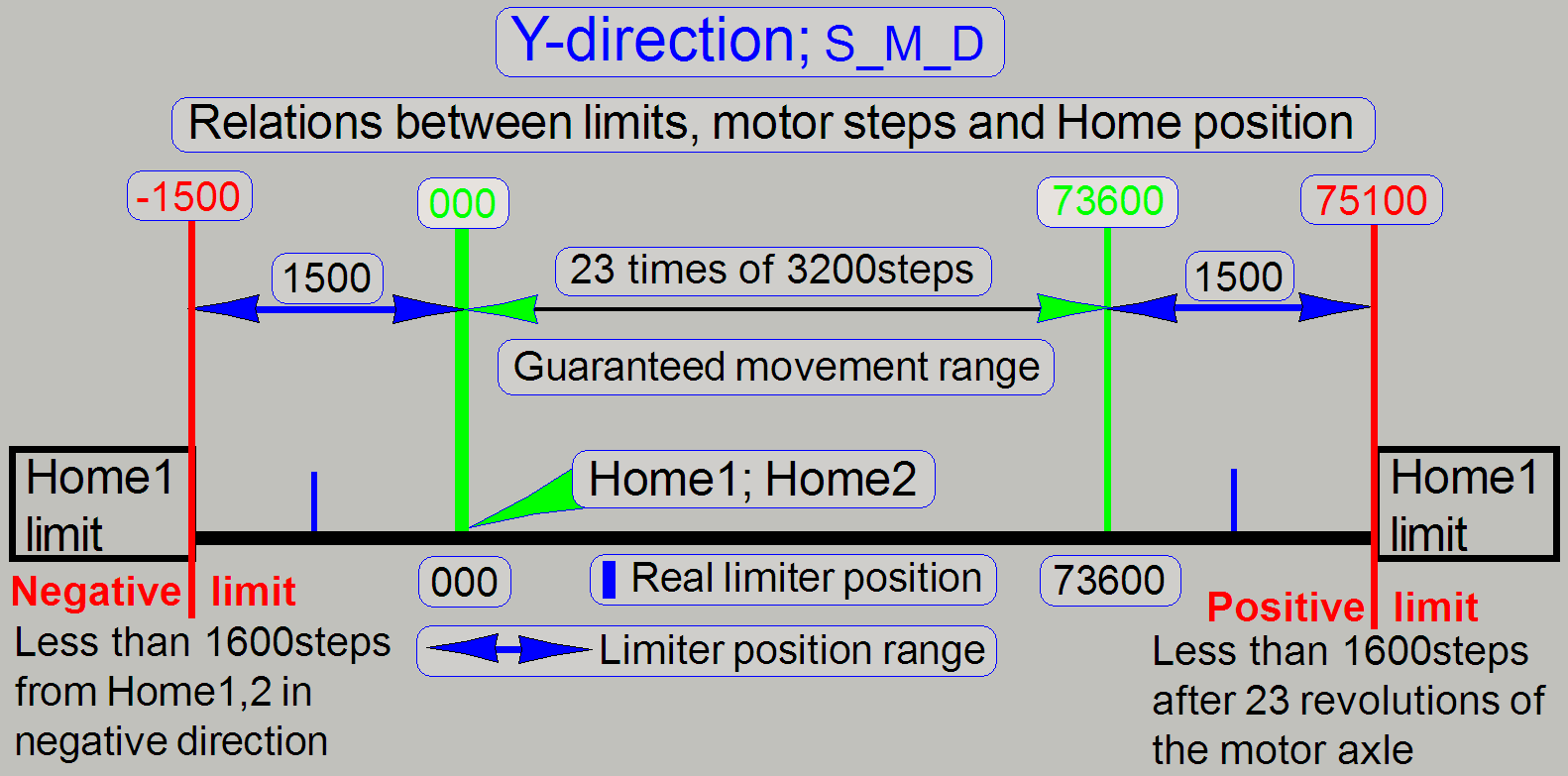 The accuracy= 100steps (0.1mm)
Negative limit
-1500steps ≤ “ObjectGuideYMin” < Home1,2
Positive limit
73600steps < “ObjectGuideYMax” ≤ 75100
Pannoramic
SCAN
Important restriction!
To
avoid collision of the slide clamp with the focus pin holder, the possible
upper limit of the Y-carriage can not be used as hardware limit!
·
Move the Y-carriage in direction to
the limit “Y-max” until a gap of 0.1mm (= 100 steps) exists between the focus
pin holder and the slide clamp (mounting)!
The value is found in the near of
73000 steps
· Use the found
value as hardware limit Y-max!
Other related or affected sections and parameters: none
See also: “X-Y-stage
unit” and “Find the
hardware limits”
Focus unit; DESK,
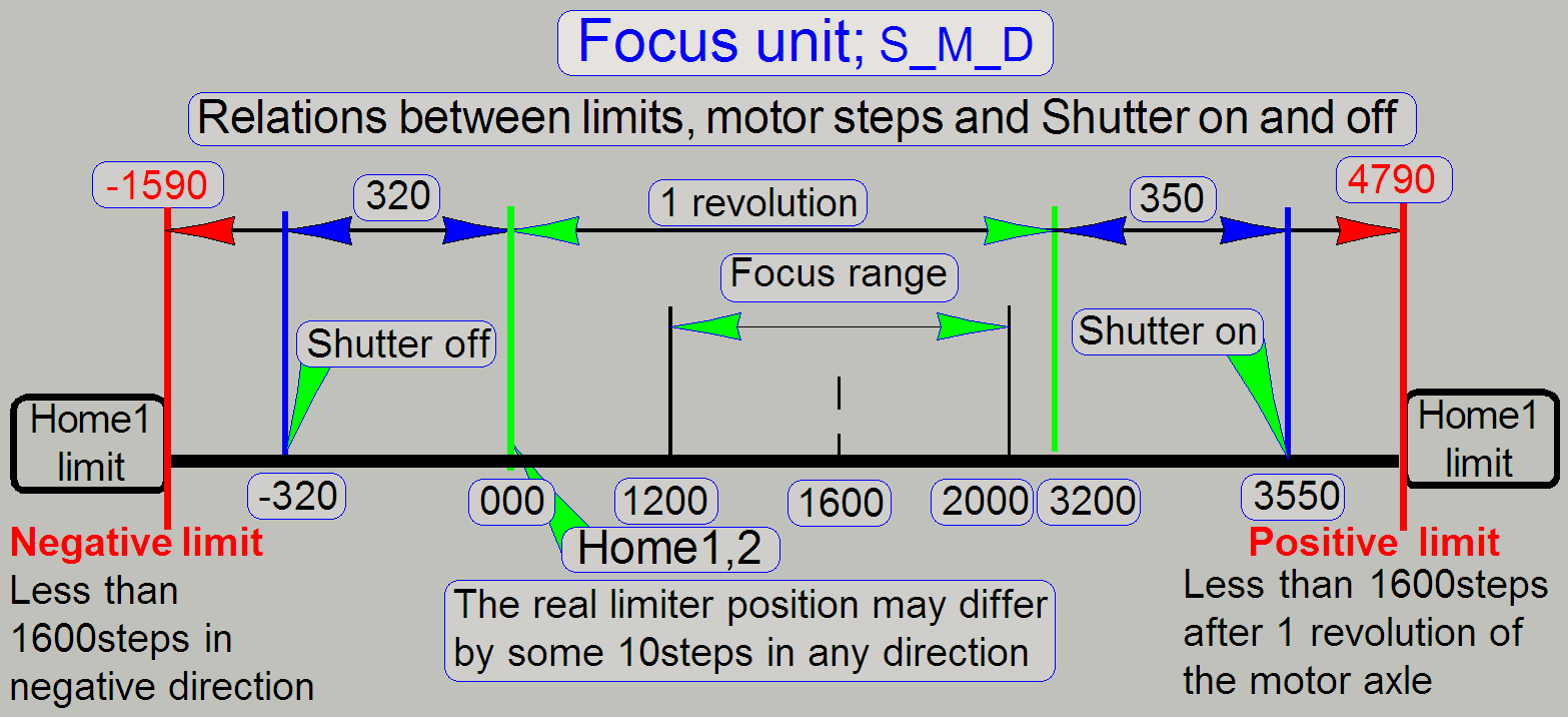 Parameters: [HardwareLimits] “FocusDeviceMin”; “FocusDeviceMax”
· The accuracy= 10steps
Negative limit
-1590steps ≤ “FocusDeviceMin” < Home1,2
Other related or affected sections and parameters:
[Focus]; CondenserCoverOff
Positive limit
3200steps < “FocusDeviceMax” ≤ 3550
Other related or affected sections and parameters:
[Focus];
CondenserCoverOn
See also: “Adjust the
ex-center position” and “Find the
hardware limits”
Remarks
· The focus motor
has a resolution of 3200steps / revolution; so the limit of “Home1” is defined
less than 1600steps.
· The hardware limit
is defined by the shutter wire and the shutter arm.
· The real limit
position depends on the adjusted ex-center position and may vary by some
10steps.
Reflector turret
unit; S_M (gear driven)
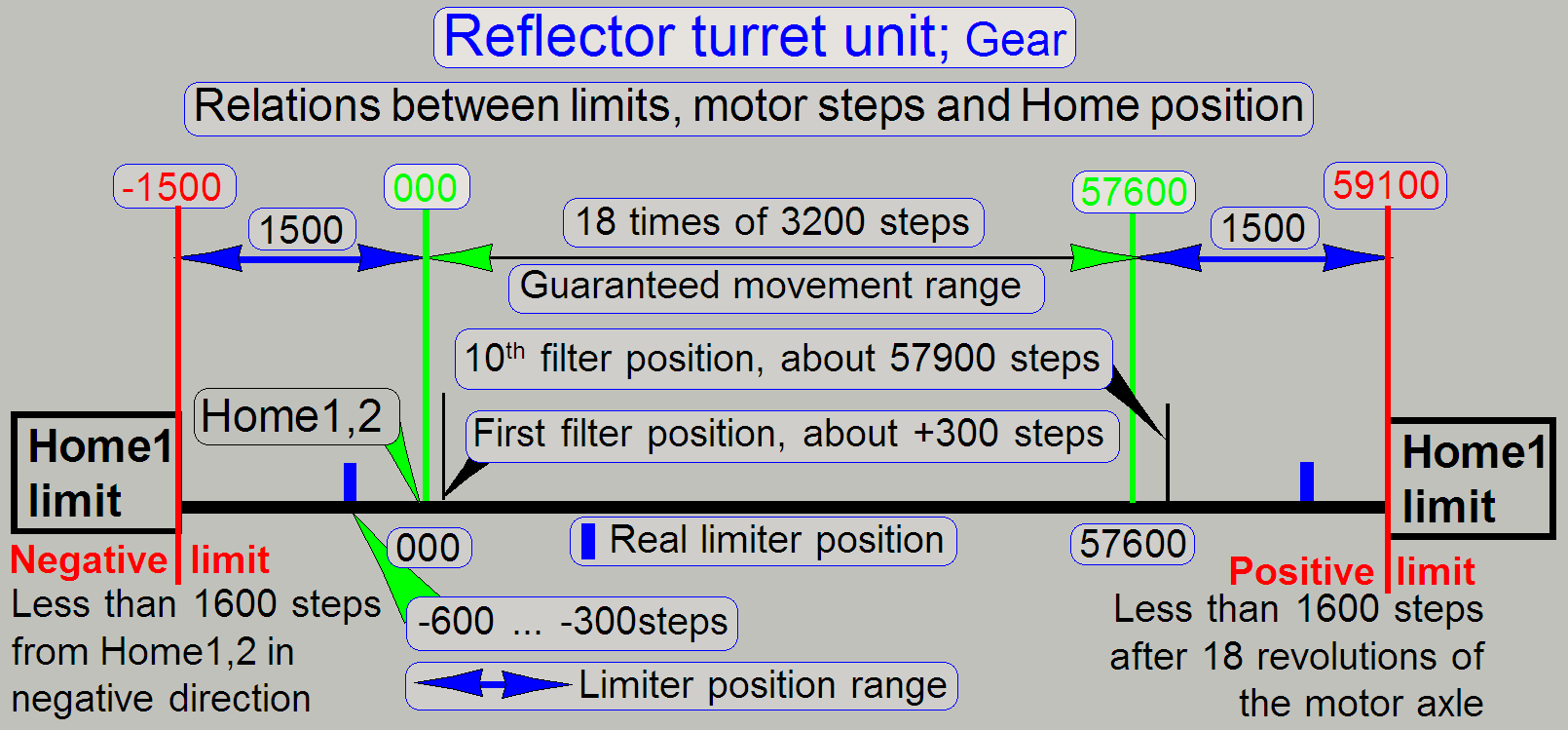 Parameters: [HardwareLimits] “ReflectorTurretMin”;
“ReflectorTurretMax”
Parameters: [HardwareLimits] “ReflectorTurretMin”;
“ReflectorTurretMax”
· The accuracy= 100steps
Negative limit
-600steps ≤
“ReflectorTurretMin” ≤ -300steps; see also: “Adjust the negative turret limit”
Positive limit
57600steps < “ReflectorTurretMax” ≤ 59100steps; see also: “Adjust the positive turret limit”
Other related or affected sections and parameters:
[ReflectorTurret]; StartingMotorPosition= see: “Find
the first filter position”
· The accuracy= 10steps
See also: “Hardware construction” and “Adjust the filter selector wheel and the mechanical
drive”
End