Housing, construction; M_II
For technicians!
This chapter handles components of
the housing and mechanical construction of the scanner Pannoramic MIDI_II (M_II).
The housing of the

Rear wall
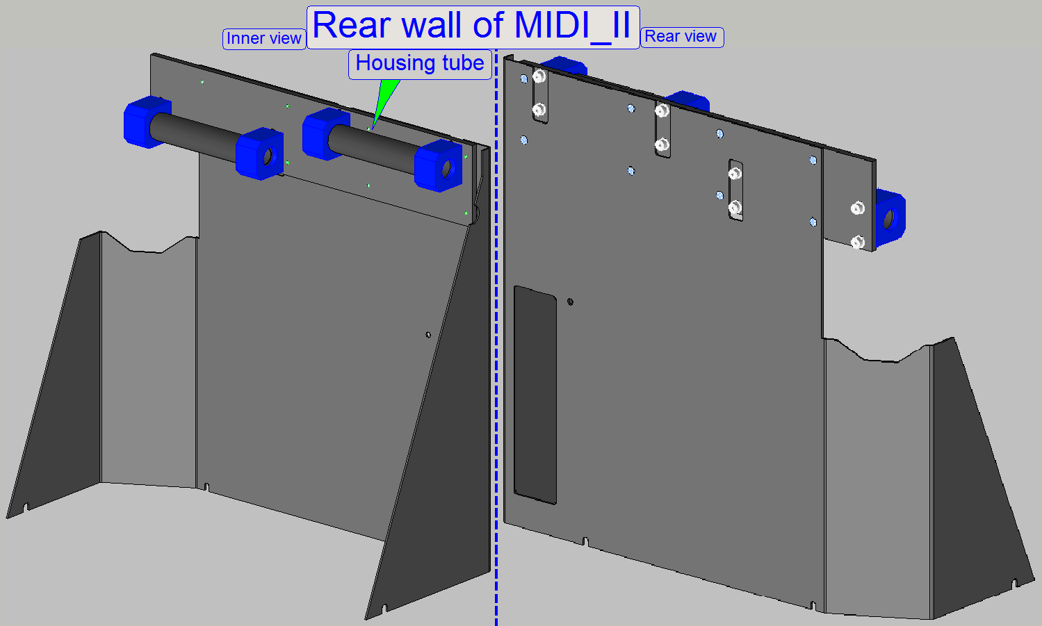 The rear wall covers the MIDI_II from the rear and
holds the housing tubes for the upper mounting rods of the shells.
The rear wall covers the MIDI_II from the rear and
holds the housing tubes for the upper mounting rods of the shells.
Slide holder tray
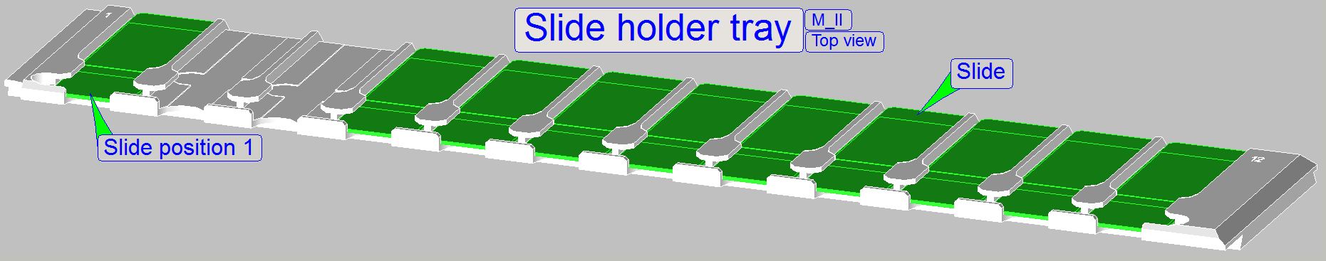 The slide holder tray contains 12 slide bays and is designed
to hold 12 slides of single width and allows so an autonomic slide insert and
remove procedure.
The slide holder tray contains 12 slide bays and is designed
to hold 12 slides of single width and allows so an autonomic slide insert and
remove procedure.
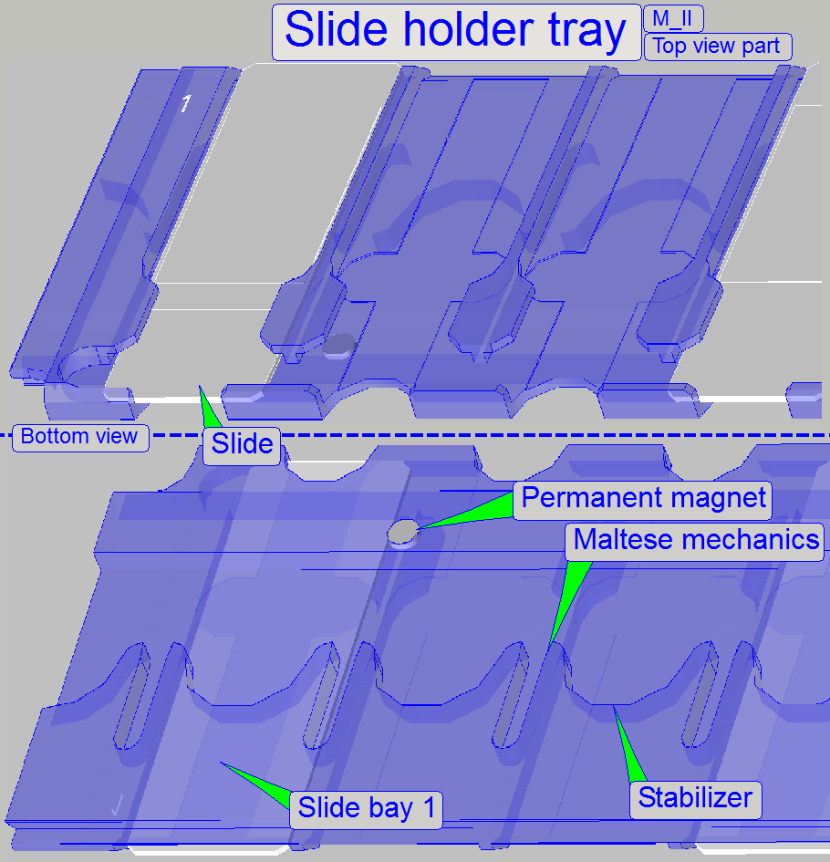 Construction of the slide holder tray
Allowed
slide dimensions are

Length: 75.00
to
Width: 25.00
to
Thickness: 00.95
to
Since January
- If the first character of the serial number is an
“S” the tool is used to check the slide dimensions
of the scanners “SCAN, “
- If the first character of the serial number is a “P” the tool is used to check the
slide dimensions with a thickness of 1.20mm.
·
Please check
the slide dimensions before filling the tray with slides!
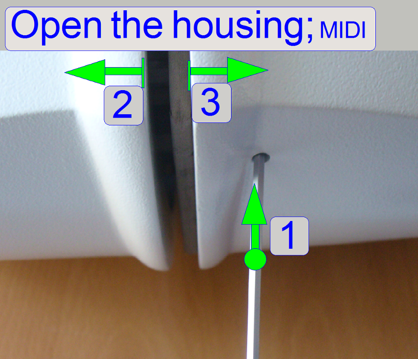
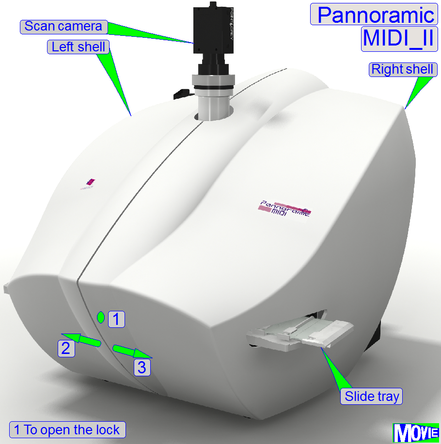
1.
Press a
2.
The left shell and the right shell respectively can be
moved sideward by about 20cm to open the housing, as shown (2,3).
3.
If the shell is fully pulled sideward, the shell will
be removed; there is no further security.
If the shells are inserted into the upper and lower housing tubes from
the left side and from the right side respectively, press the shells to each
other until the lock snap-in.
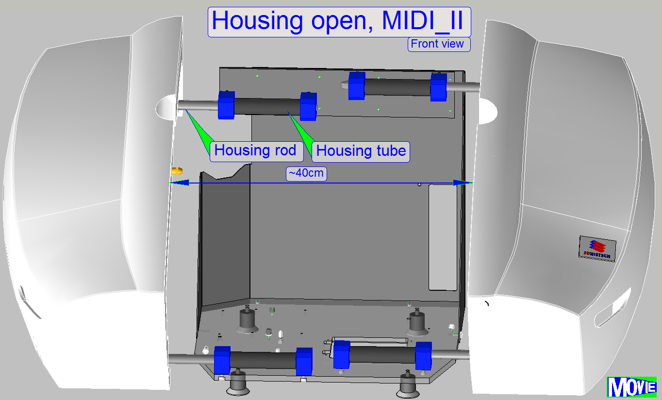
The shells can be opened to reach internal units for services or
maintenance.
- The width of
the reachable working space is about 40 ~ 50cm.
Right
shell
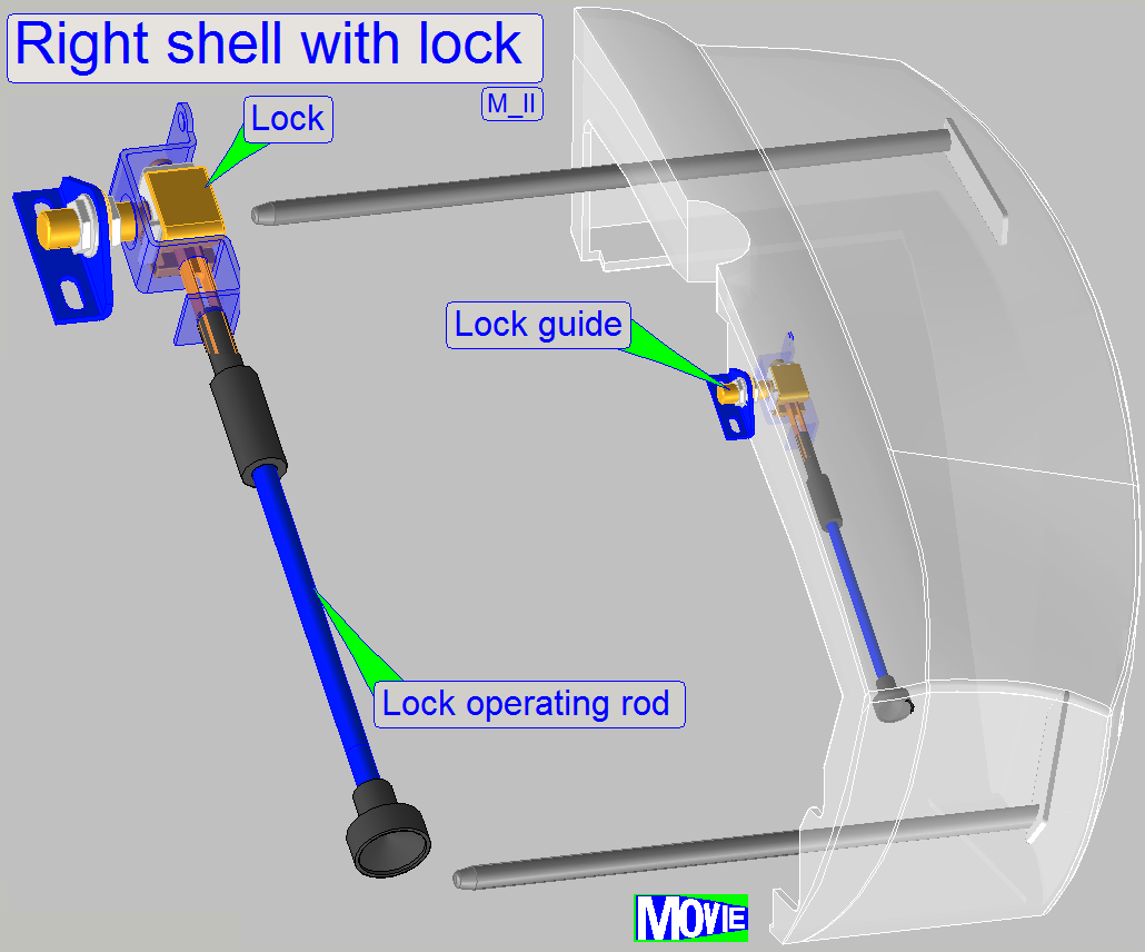
The right shell contains the lock with operating rod, while the left
shell holds the lock guide.
Lock
construction
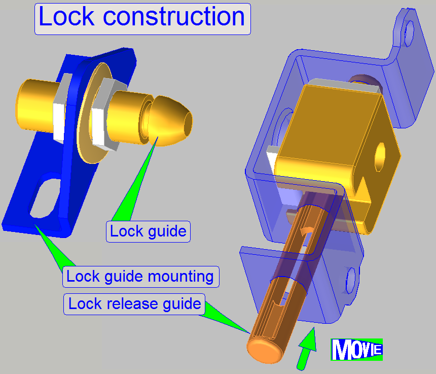 Manufacturer: Southco
Type: E2 Push-to-close-latch
(stored)
Part
Number: E2-50-101-20
1.
 Remove the cover shells as described above
2.
Remove
all the cables from the USB controller
3.
Remove the mounting bolt of the USB controller
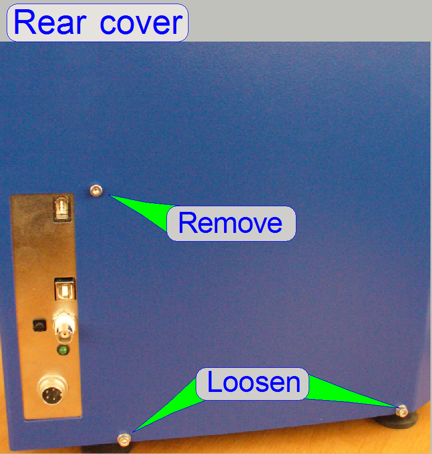
4.
Loosen (or remove) the 4 mounting bolts of the rear
cover to the base plate (only two are shown, the other two bolts are fixing the
rear cover from the left side and the right side respectively).
5.
The rear cover can be now removed upward.
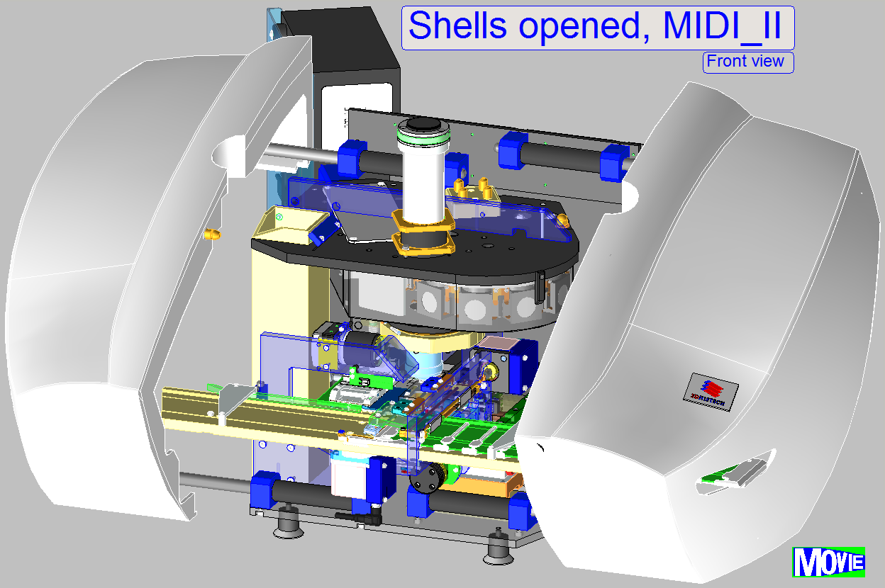
By opening the shells, internal units can be reached.
By removing of one or both shells, the scanner is dismantled.
- Easily pull
the shells fully sideward, there is no further
security.
In this chapter
only main differences are described, in relation to the SCAN_II. For not shown
components and parts, please refer to the appropriate description of the
SCAN_II.
 Principally, the
Onto the scanner unit front side the tray loader unit is mounted (not
shown here).
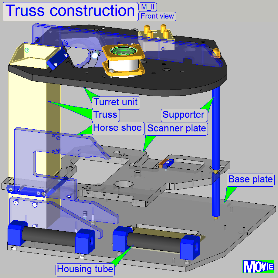
Watch video: “Truss construction”
·
 In the
·
In opposite to the
SCAN, the image path is
arranged in vertical direction, so the arrangement of the components is
modified.
The truss and base plate contains the mountings for:
· Housing tubes
· Rubber feet
(mounted from beneath)
· Base plate cover: To check the correct cabling of the RGB
BF-illumination unit, the base plate cover can be removed.
· For more information
please refer to the description of the SCAN, “Truss” and “Scanner plate”.
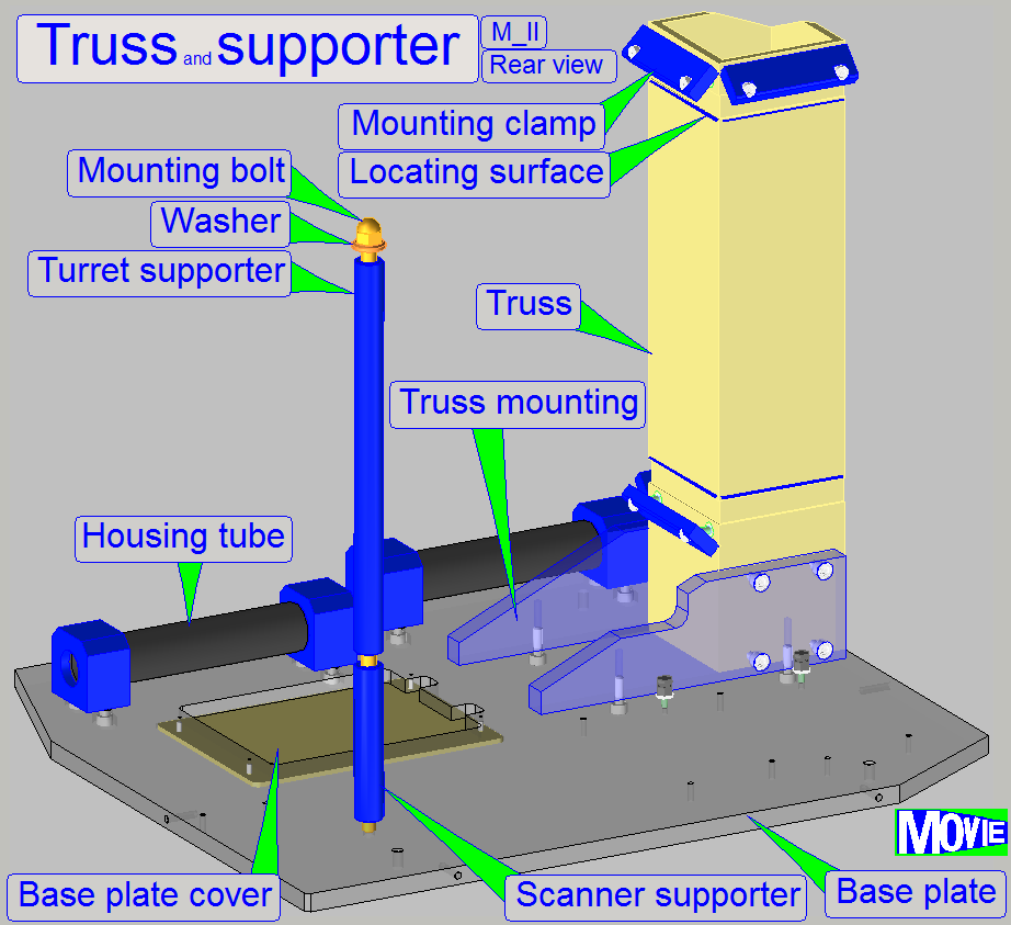
Watch video: “Truss”
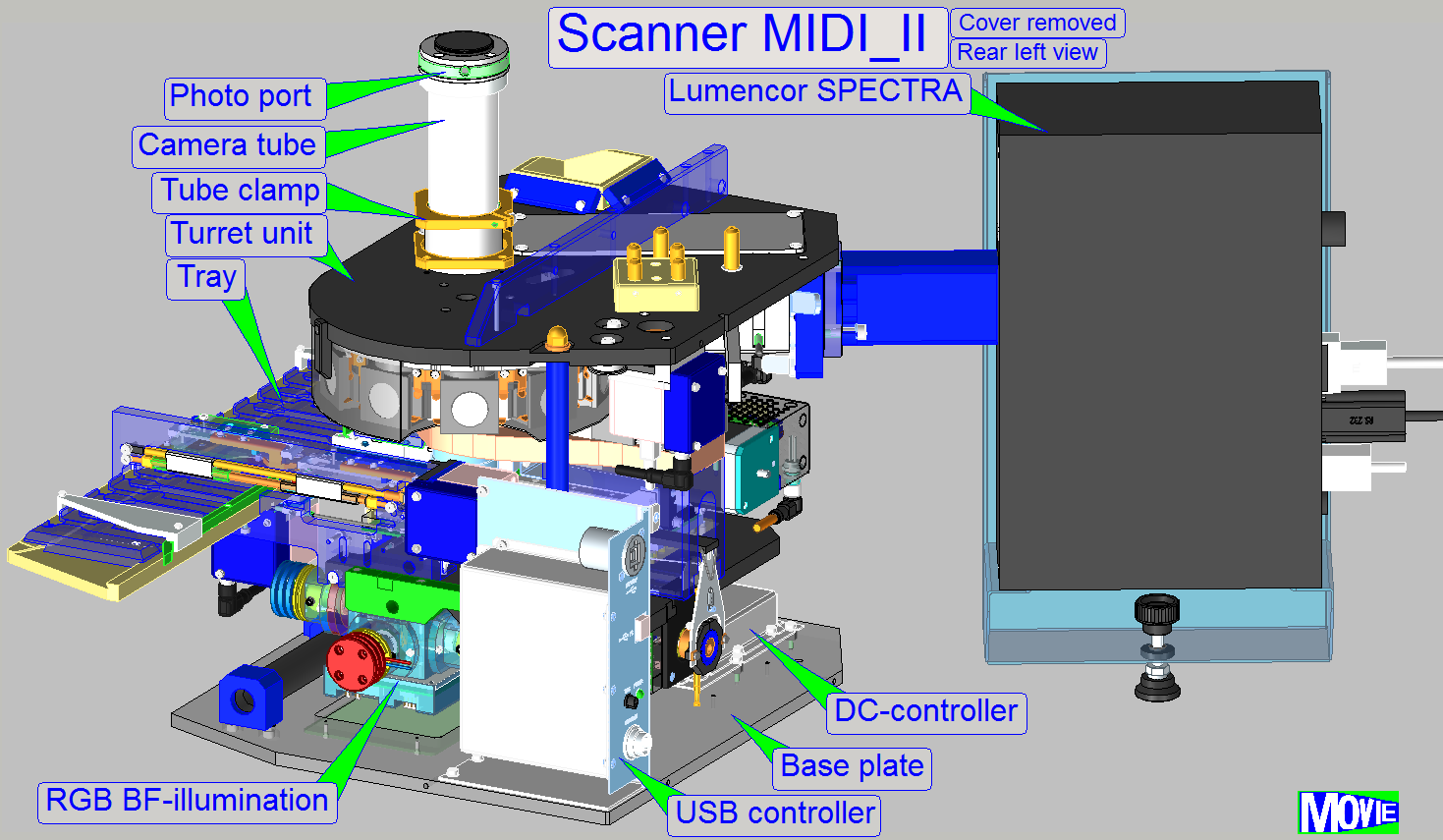
Truss and control
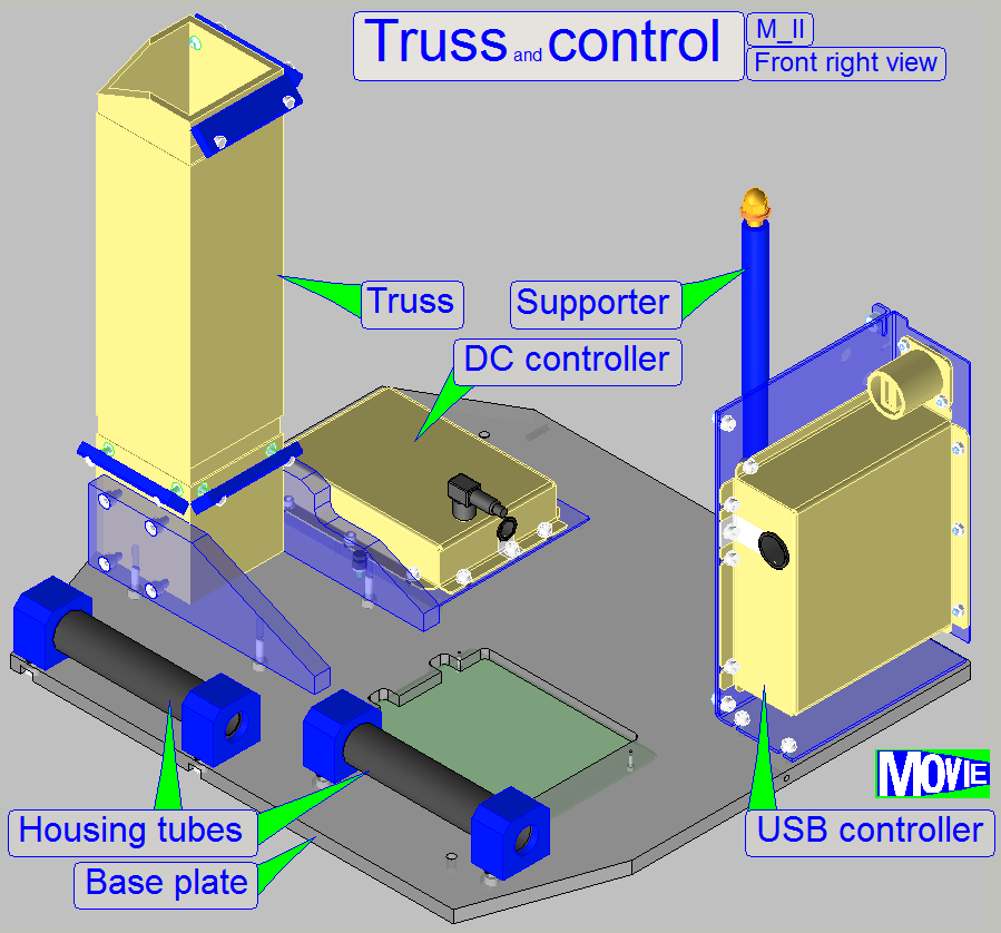 The control electronics of
the scanner is placed as shown.
The control electronics of
the scanner is placed as shown.
Watch video: Truss and control
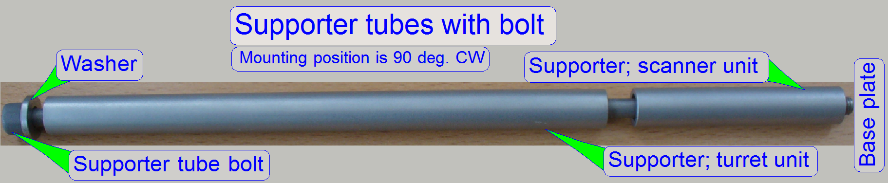 Because the scanner and turret plate is placed
horizontally, a supporter tube with bolt
increases the mechanical stability and guarantees the parallelism of both units
to each other and to the base plate.
Because the scanner and turret plate is placed
horizontally, a supporter tube with bolt
increases the mechanical stability and guarantees the parallelism of both units
to each other and to the base plate.
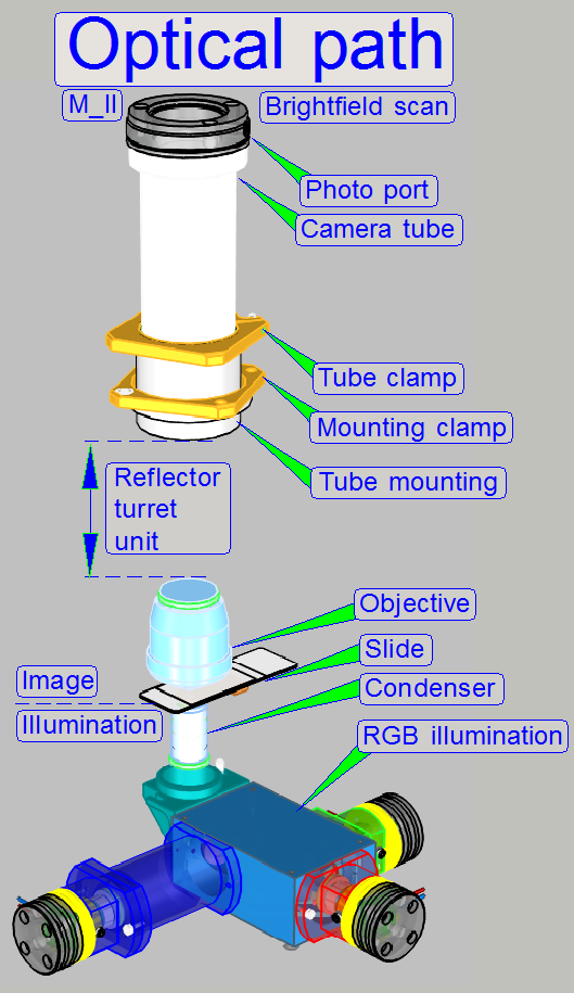 The optical path defines mainly the mechanical
components and their arrangement.
The optical path defines mainly the mechanical
components and their arrangement.
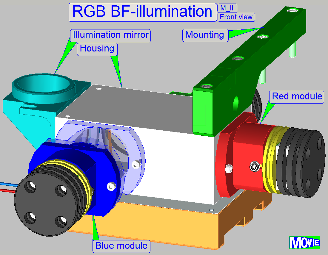
The use of an RGB BF-illumination unit allows the use of monochrome
cameras for brightfield scan and fluorescent scan procedures as well.
Exchange of the objective magnification between two scan sessions via
software commands.
Slide thickness defined between 0.95 ~ 1.20mm.
Fluorescent scan session or brightfield scan session selectable
consecutive, between 2 slide scan
sessions.
 The brightfield
illumination is mounted directly onto the scanner plate from beneath. An illumination
mirror reflects the light from the illumination tube directly to the condenser of the focus unit.
The brightfield
illumination is mounted directly onto the scanner plate from beneath. An illumination
mirror reflects the light from the illumination tube directly to the condenser of the focus unit.
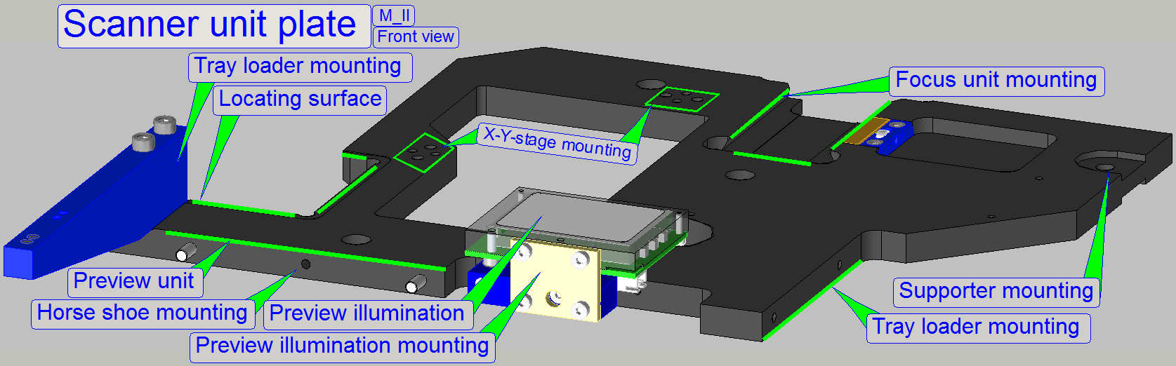
The mounted main units of the scanner plate are:
· Preview and barcode unit
(the horseshoe)
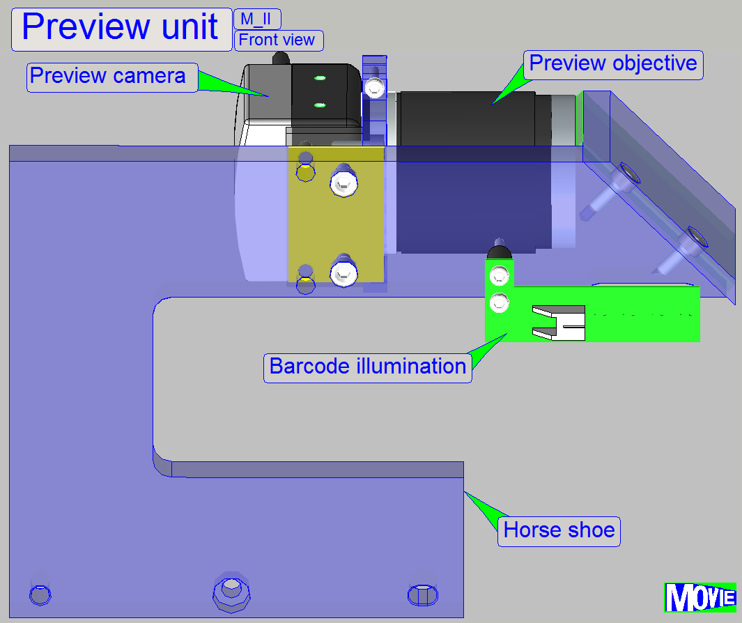
To find the position of the entire tissue to be
scanned or parts of it, a preview of the slide is made. The tissue is defined
as a darker part of the slide in relation to its surrounding.
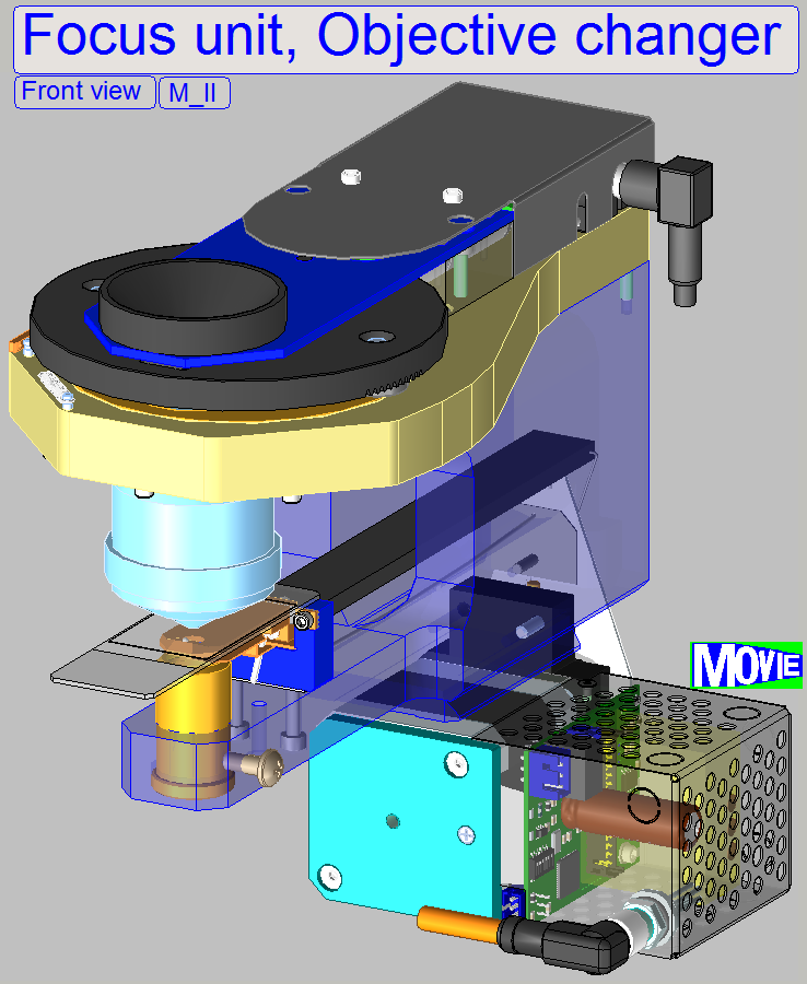
The focus unit allows focusing of slides with a thickness of 1.20mm
maximal.
Onto the focus unit the objective changer is mountet.
![]() Focus unit
with objective changer.
Focus unit
with objective changer.
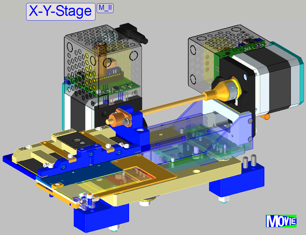 The X-Y-stage unit
is used to position the slide at loading or unloading action. It also moves the
slide in X- and Y-direction during the scan process.
The X-Y-stage unit
is used to position the slide at loading or unloading action. It also moves the
slide in X- and Y-direction during the scan process.
Allowed slide dimensions for
the specimen holder can be found here.
The movements are realized by
stepper motors. The principle of the slide insertion and specimen holding is
nearly the same in the scanners, so only small deviations are found in the
construction of the specimen holders and these will be discussed separately.
The X-Y-stage unit mounting
is modified, so a remove and remount of the unit may require excessive
adjustments.
 The construction of the BF
optical path uses only a monochrome camera, so only monochrome images can be
produced.
The construction of the BF
optical path uses only a monochrome camera, so only monochrome images can be
produced.
- Monochrome
cameras have an important advantage in relation to color cameras, today,
the pixel size is the possible smallest.
To create color information of the tissue with a monochrome camera, we
illuminate the tissue with monochrome light.
If the tissue is illuminated by blue light, and we are making an image
of the Field of view, the gray scaled camera image contains the intensity of
the blue parts in the tissue.
Because the pixel resolution of the camera is very high and the
resolution of the image's gray scale is 10bit per pixel or higher (depending on
the used camera), very detailed information of the blue part in the FOV,
related to the appropriate pixel can be reached.
If we repeating the procedure with the colors Green and Red, 3 images of
the same FOV are produced (a Red, Green and Blue image) and so, the software
knows detailed color information about each pixel of the Field Of View.
By using the software coloring method the true color information of each
pixel is found.
By using cameras with a large image sensor low shutter time and high
pixel resolution (small pixel size), the scan time of the tissue can be held in
acceptable boundaries and the result is an image with high resolution and high
color fidelity.
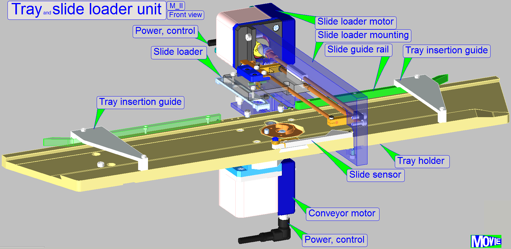 The unit allows an autonomic
slide load and removal operation by the help of a slide tray.
The unit allows an autonomic
slide load and removal operation by the help of a slide tray.
Detailed information about the unit
![]() the chapter Tray and slide loading.
the chapter Tray and slide loading.
Watch video: Tray and slide loader
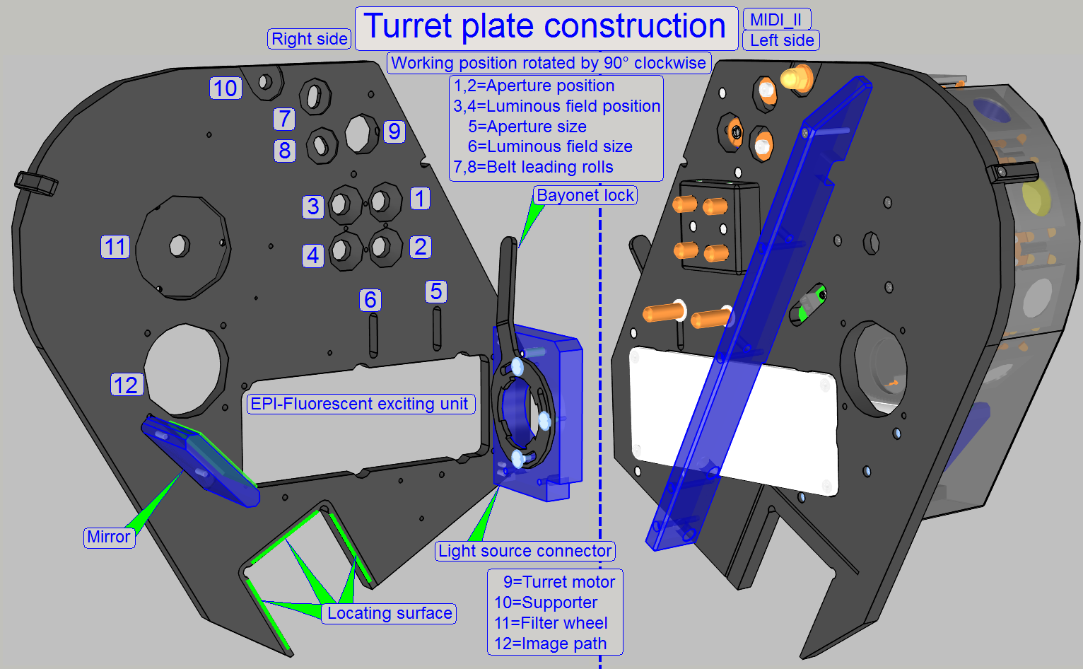 With the locating surface, the correct distance between
turret plate and scanner plate is defined; the turret plate is mounted by the
use of clamps and
contains the mountings and fixings for the following main units:
With the locating surface, the correct distance between
turret plate and scanner plate is defined; the turret plate is mounted by the
use of clamps and
contains the mountings and fixings for the following main units:
·
EPI-fluorescent
illumination unit
The unit is identical in the SCAN_II and the MIDI_II but the mounting
position is rotated by 90° clockwise.
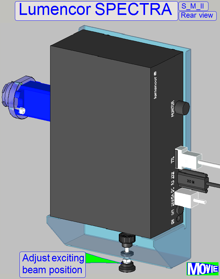
The light emission unit is used to excite the fluorescent tissue during
FL scan sessions.
- To find the
right position of the light exciting path the height of the unit can be
adjusted by the foot.