Tour 3: Optical path; P250
designed for technicians
This chapter should help you to go familiarly with the Pannoramic
scanner P250.
The entire construction of the scanner is based on its optical path and
the slide loading construction.
In this chapter, the optical path of the scanner part will be shown and
the used components are introduced.
Optical path of the Pannoramic 250
· To allow an
exchange of the scan camera, a mirror is used in the image path.
Introduction
of components
A detailed description of the used components can be found in the
chapter “Components and
construction” of the file
“P250_Optics_Illumination.htm”
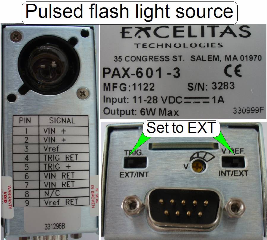 Pulsed
xenon flash light source
Pulsed
xenon flash light source
· Precision
adjustment of the light arc; it is situated correctly on the optical axis.
· The light arc is
pulsed together with the camera trigger by control of software.
· The intensity of
violet and blue rays is very much.
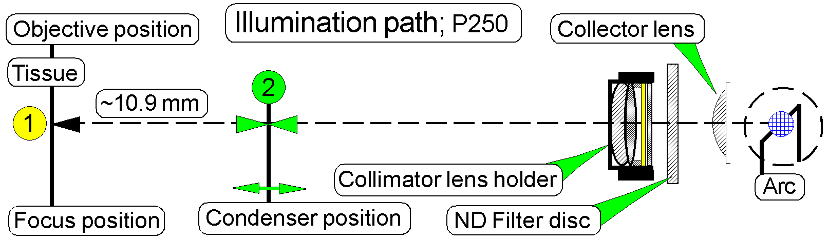
The flash light source creates the light arc, used to illuminate the
Field Of View (FOV) in the brightfield scan mode.
The pulse frequency may be more then 1kHz; it means, the scan camera can
make more than 1000 images /second.
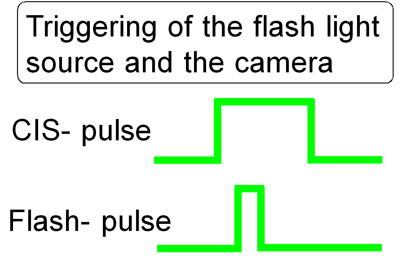
To create the arc during the camera is ready; the flash light source, as
well as the shutter of the camera is triggered (synchronized) by the firmware
of the control electronics; the flash light pulse is started if the shutter of
the brightfield camera is already open.
Neutral density (ND) filter unit
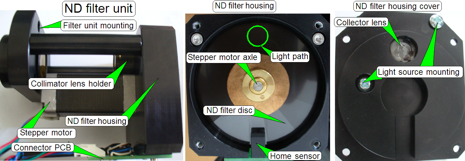
- The ND filter
unit is used to adjust the brightness of the light, emitted by the pulsed
light arc.
- The Home
position of the stepper motor is defined by the transition from black to
white of the filter disc.
- The stepper
motor rotates the filter disc and so, the desired intensity of the
brightfield illumination can be found.
The mounting
· The flange of the
ND filter unit is mounted with four mounting bolts to the scanner plate.
Remove the mounting bolts and pull the entire ND filter unit to the
right.
·
No adjustments are needed
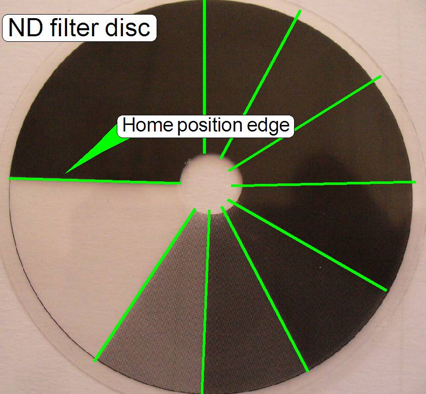 The ND filter
disc consists of sectors with different intensity of gray filter zones
from white (fully translucent) to black.
The ND filter
disc consists of sectors with different intensity of gray filter zones
from white (fully translucent) to black. - The
appropriate gray level intensity of the ND filter disc is selected by the
software during the calibration of the exposure time for the brightfield
camera; by rotating the disc with the ND motor, the intensity of the
illumination can be selected / adjusted.
- Usually, the
fifth sector after white is used, but during the aging process of the
light arc (after some years) the used sector may be closer to white; this
way, the aging of the light source can be handled also.
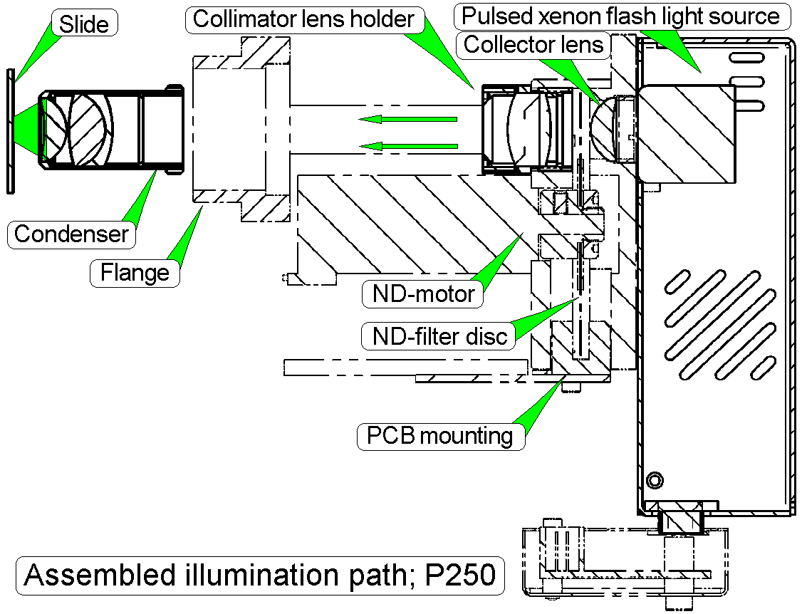
The collector lens concentrates the light, emitted from the light arc,
and sends it to the ND filter.
·
Maintenance is not required
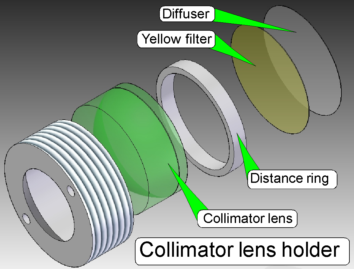
 In scanners the illumination
of the tissue is very important. The collimator lens holder contains the optics
to produce light with a high density and coherent rays; so, the field of view
can be illuminated evenly.
In scanners the illumination
of the tissue is very important. The collimator lens holder contains the optics
to produce light with a high density and coherent rays; so, the field of view
can be illuminated evenly.
Components of the collimator lens holder
1.
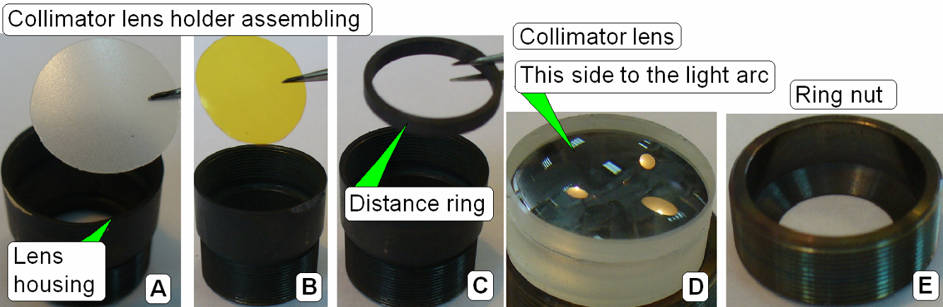 Housing; insert the
diffuser foil first
Housing; insert the
diffuser foil first
2.
Insert the yellow filter next.
3.
Insert the distance ring; it keeps the convex surface
of the lens away from the yellow filter.
4.
Collimator lens; the surface of the thinner lens part
shows to the light arc.
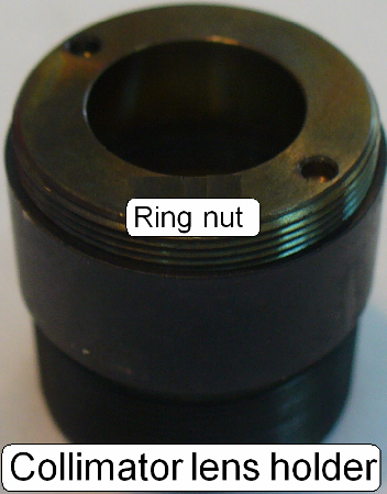
5.
Ring nut
- Because the
blue and violet part of the emitted light is very much; the yellow filter
helps to create a “more white” light.
- The diffuser
foil insures the homogeneity of the light rays.
- The
collimator lens creates nearly parallel light rays.
·
No adjustments are needed.
·
Maintenance is not required.
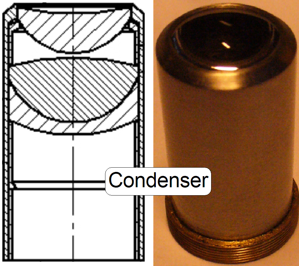
The condenser concentrates the
incoming light to the field of view (FOV).
Because the size of the illuminated part
of the tissue is critical, the condenser position can be adjusted; the focus
position is 10.9mm nominal.
Remark
The best illumination results would be reached if we would use an
objective also to illuminate the field of view; but because objectives are very
expensive, a condenser is used.
· In view of optical
aspects we can say, the condenser is a simplified objective.
Assembled illumination path
Objective
 In scanners, the objective gathers the light, emitted
from the tissue to be observed and focuses the rays to produce an image. The character
of the objective is given by the magnification and the numerical aperture.
In scanners, the objective gathers the light, emitted
from the tissue to be observed and focuses the rays to produce an image. The character
of the objective is given by the magnification and the numerical aperture.
The position of the objective and
the distance to the tissue is very important to produce a focused (sharp)
image. Because in Pannoramic scanners this distance can be modified by moving
the tissue position on the Z-axis (focusing) both positions are important, the
objective position and the nominal focus position.
Remark
 The exchange of the objective is performed by the
Objective Changer Unit. This way, the objective magnification can be easily changed,
software controlled, between two slide scan sessions.
The exchange of the objective is performed by the
Objective Changer Unit. This way, the objective magnification can be easily changed,
software controlled, between two slide scan sessions.

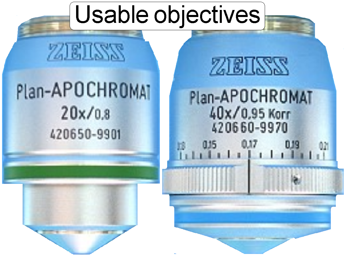
On the scale of the 40x
objective, the thickness of the cover slip should be selected.
·
If the real thickness of the cover slip differs from
the selected / adjusted value, the quality of the scanned FOV may be reduced!
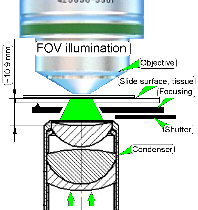 Objective
and condenser
Objective
and condenser
The parallel light rays, created by the aspheric lens and the diffuser
are focused by the condenser to the field of view, observed by the objective
pupil.
To reach a sharp (focused) image, the slide is moved in Z-direction
toward or away from the objective pupil, in the defined focus range.
· Because the tissue
may vary in thickness, the actual focus position must be checked and adjusted
always during the sample scan process.
Focus unit with
objective changer
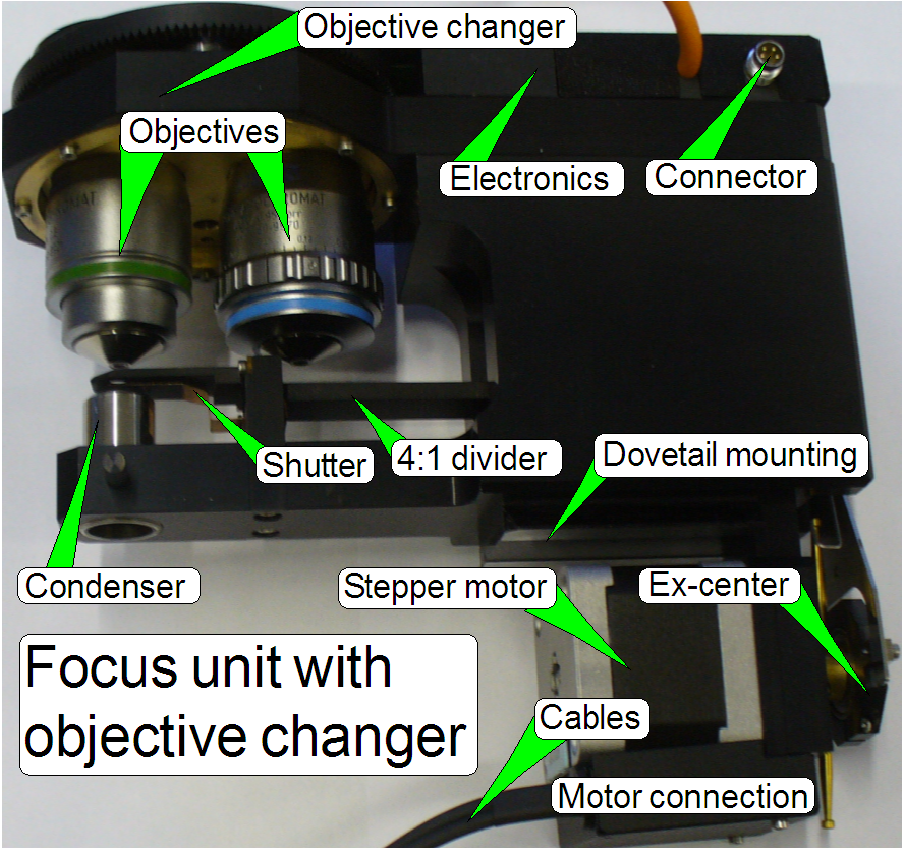
The focus unit gives the
possibility of focusing the FOV
(field of view, seen by the scan camera with 1 exposure) automatically during
the scan process of the sample.
The objective changer unit is mounted onto the focus
unit and allows the consecutive use of two, preinstalled objectives. The
selection or exchange of the objective is initiated by software before a slide
scan session is started. The movement of the objective holder disc is executed
via a DC-motor and the position is sensed via Hall sensors. Each objective
position has a separate hall sensor, so the software knows always which
objective is actually in use. To guarantees the proper position of the objective
in the light path, the final objective position is fixed via a form-fit
mechanism.
The unit was developed for
the use of objectives of the following types:
Plan-APOCHROMAT
20x/0.8 and Plan-APOCHROMAT
40x/0.95
If the mechanical dimensions
do not exceed the size of the Plan-APOCHROMAT 40x0.95 type objective, the
mechanical mounting is identical and the focus distance of the objective to the
tissue is not closer then 0.25mm, other kind of objectives can be used also but
it is strongly not recommended! Always check with 3DHISTECH first if a different
objective should be used!
More information can be found in the chapter: “Focus
unit with objective changer”
Watch video: “Objective change’
·
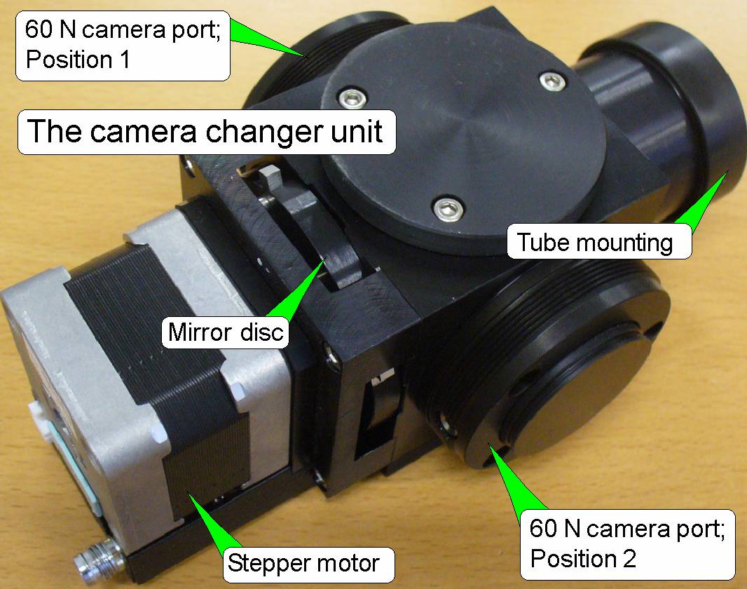
 The camera changer reflects the image to the brightfield
camera in the position 2 or to the fluorescent scan camera in the position 1
respectively, depending on the selected scan session mode.
The camera changer reflects the image to the brightfield
camera in the position 2 or to the fluorescent scan camera in the position 1
respectively, depending on the selected scan session mode.
·
In the front of
the camera tube part, the tube lens is situated; this performs the image
(together with the objective).
·
Into the space
between objective and tube lens further optical components can be inserted,
like the filter block for the fluorescent scan session.
·
For best image
quality, the tube lens should be mounted into the camera changer tube until it stops!
·
Camera adapters
with 60 C1 mounting can be also connected to the 60N interface.
See also: “Camera changer
unit”
·
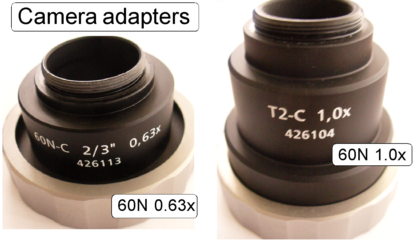 The camera adapter is situated between the camera tube
and the scan camera and offers the possibility to insert lenses or other optical
means like filters into the image path.
The camera adapter is situated between the camera tube
and the scan camera and offers the possibility to insert lenses or other optical
means like filters into the image path.
·
If lenses are
inserted, the camera adapter modifies the image size and the magnification.
·
The usable
magnification of the camera adapter depends on the scan camera’s CCD size and
resolution and the construction of the optical path.
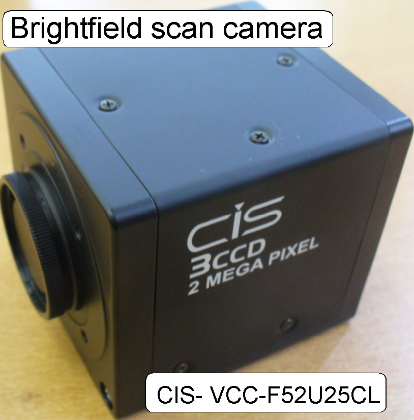
BF scan camera
 The charge coupled device (CCD) of the scan camera
transforms the incoming light (the image) into electrical charge; and this is
read out by the electronics of the camera.
The charge coupled device (CCD) of the scan camera
transforms the incoming light (the image) into electrical charge; and this is
read out by the electronics of the camera.
The VCC-F52U25CL is a camera link
interfaced, 3CCD high-resolution industrial color video camera module utilizing
a 1/1.8 type PS IT CCD. The 2M pixels CCD image sensor with on-chip
micro-lenses realizes high sensitivity and high resolution. The full size field
of view can be read out within approx. 30fps.
See also: “VCC-F52U25CL”
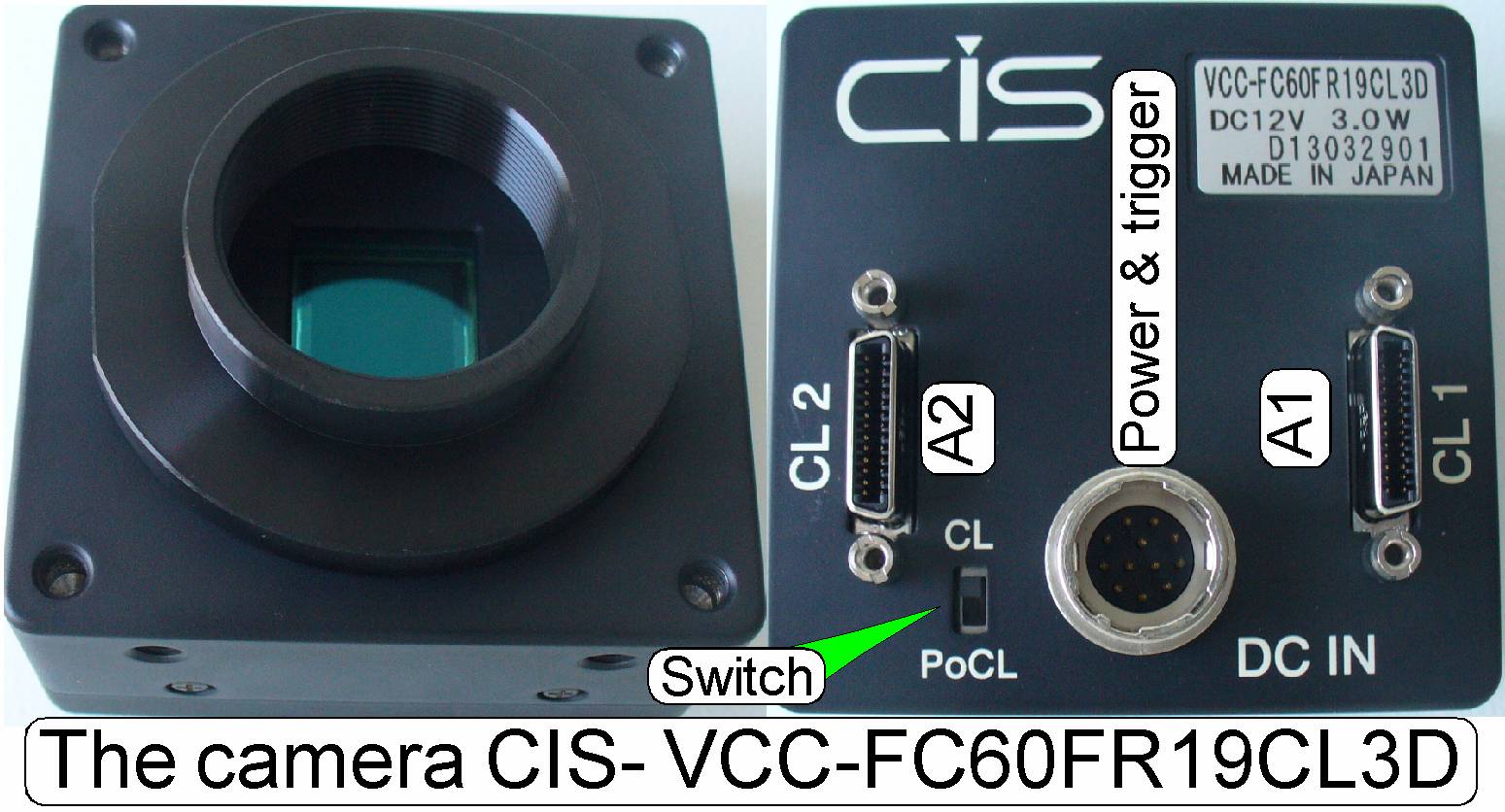 The VCC-FC60FR19CL is a camera link interfaced, 4Mpixels high-resolution
industrial color video camera module. The 4M pixels global shutter CMOS sensor
realizes high sensitivity and high resolution. The full size field of view can
be read out within 135fps, depending on the configuration.
The VCC-FC60FR19CL is a camera link interfaced, 4Mpixels high-resolution
industrial color video camera module. The 4M pixels global shutter CMOS sensor
realizes high sensitivity and high resolution. The full size field of view can
be read out within 135fps, depending on the configuration.
See also: “VCC-FC60FR19CL”
FL scan camera
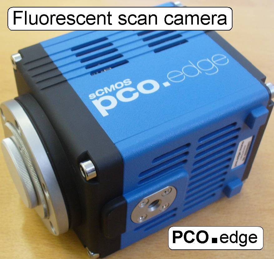 The pco.edge is a camera link interfaced, monochrome
camera and is used for scanning of stained tissues in the fluorescent scan
mode. The color (wave length of the light) is defined by the used filter block
and the gray scale image, taken by the pco.edge camera, defines the partial
intensity. By using the software coloring method, images of a very high quality
and color fidelity can be produced.
The pco.edge is a camera link interfaced, monochrome
camera and is used for scanning of stained tissues in the fluorescent scan
mode. The color (wave length of the light) is defined by the used filter block
and the gray scale image, taken by the pco.edge camera, defines the partial
intensity. By using the software coloring method, images of a very high quality
and color fidelity can be produced.
The large resolution of 5.5 Mpixels
realized on a scientific CMOS sensor with a full resolution of 2560 x 2160
pixels allows a large size of the field of view (FOV) and the transfer rate of
100fps (full size) makes high scan speeds possible.
See also: “PCO.edge”
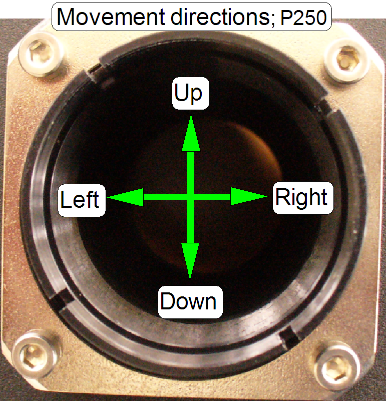
Illumination path adjustments
![]() Set the focus position to the calculated number of steps
and adjust the objective position until the tissue is in focus; then hold the
distance between objective and tissue constant during the entire adjustment
procedure.
Set the focus position to the calculated number of steps
and adjust the objective position until the tissue is in focus; then hold the
distance between objective and tissue constant during the entire adjustment
procedure.
Use always the found number of focus steps during the
adjustment!
![]()
Adjust
the condenser position
See also: Check / adjust the
objective position
and Adjust the condenser
position
The entire image path adjustment
includes the adjustment of the following parts:
1. The objective
position
This
adjustment ensures that tissues with different thicknesses can be scanned in focus;
of course, it was adjusted previously for the brightfield illumination, but the
objective position should be checked / adjusted again. If the objective
position is incorrect, the tissue or parts of it can not be scanned in focus;
see also “Check the optical path adjustments”
Check also the tightness of the objective in its mounting.
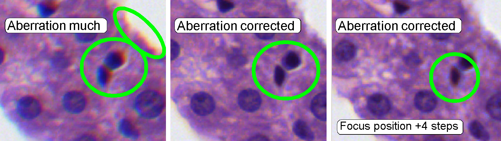
2. The camera tube
position
The
position of the camera tube (lens) affects the color trueness of the scanned tissue;
the chromatic aberration becomes visible in more blue, and more red or yellow
colored cell borders on the opposite sides; see also “Chromatic aberration” and
“Adjustments”.
If
the camera rotation angle is out of the limits, the stitching is not correct
and the borders of the FOV’s becoming visible in the virtual tissue with the
viewer program, the sample does not fit on the border of the FOV; see also
“Stitching’.
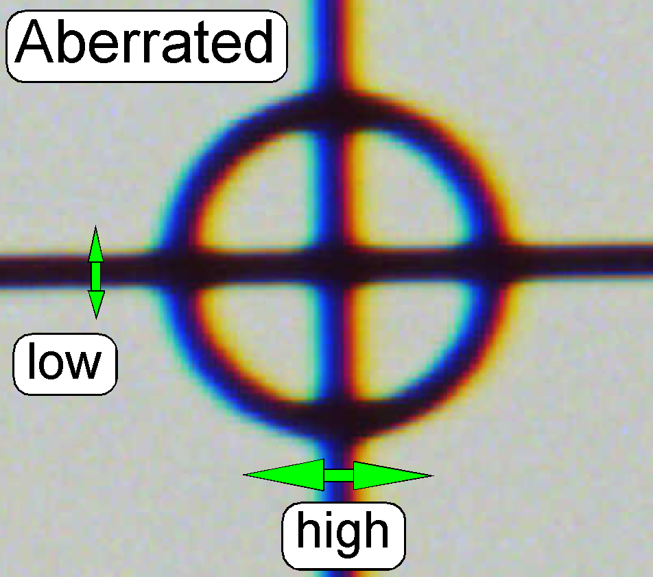
Chromatic aberration
 The appearance of
chromatic aberration can be divided into two main reasons:
The appearance of
chromatic aberration can be divided into two main reasons:
1.
The used materials (the composition of the glass) in
the lens system; different wavelengths of light will be focused to different
positions; and
2.
The arrangement of the lenses to each other
(centermost), with other words, the straightness of the optical path (lens
system).
More information can be found
here: Chromatic
aberration
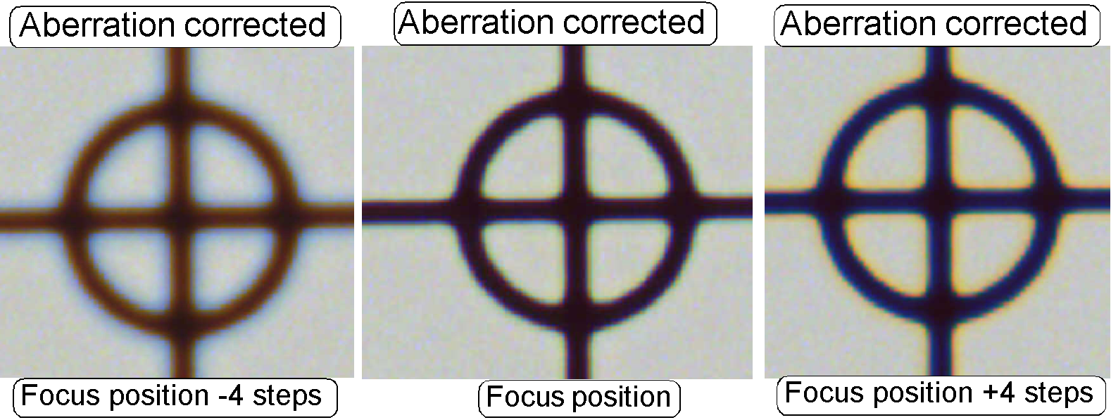 The adjustment of the chromatic aberration is done in
the real focus position and in the center of the FOV to be observed. To check
the result of the adjustment, the focus position can be modified by some steps
in positive or negative direction. In this way, the correctness of the
adjustment becomes more visible. If the yellow color occurs evenly on the inner
and outer part of the circle in the center, the adjustment is acceptable; see
“Focus position +4 steps”.
The adjustment of the chromatic aberration is done in
the real focus position and in the center of the FOV to be observed. To check
the result of the adjustment, the focus position can be modified by some steps
in positive or negative direction. In this way, the correctness of the
adjustment becomes more visible. If the yellow color occurs evenly on the inner
and outer part of the circle in the center, the adjustment is acceptable; see
“Focus position +4 steps”.
The images was done in the focus
position of the live view, except otherwise specified and with a zoom factor of
2,73
 The tube is mounted so, that the correct position can
be adjusted; with this adjustment the chromatic
aberration is corrected (minimized).
The tube is mounted so, that the correct position can
be adjusted; with this adjustment the chromatic
aberration is corrected (minimized).
·
For
adjustments, loosen the four mounting bolts to make the tube mounting barely
moveable.
·
See also “Chromatic aberration”
and “Reduce
chromatic aberration”.
Stitching errors have two main
reasons:
1.
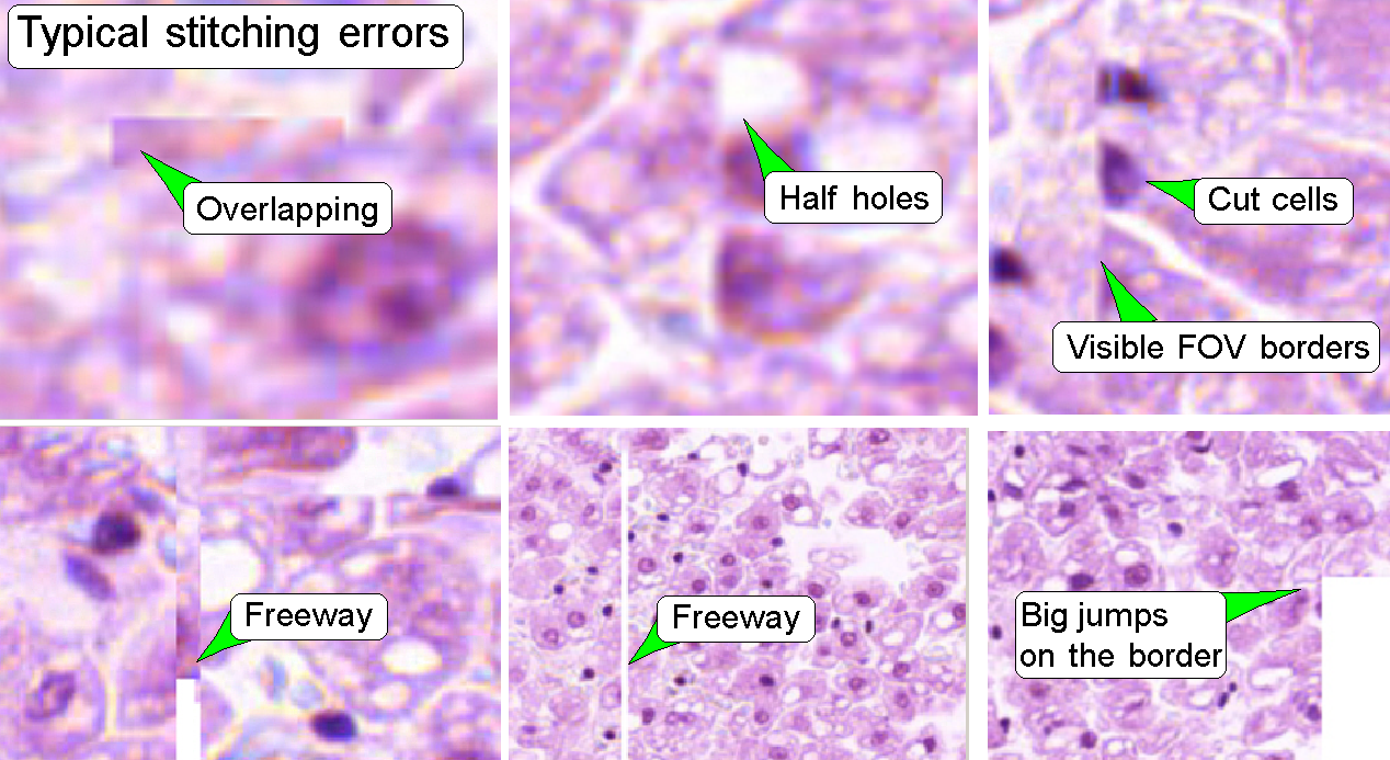 Improper adjusted scan camera rotation angle and
2.
The hysteresis in
Y-direction is too much.
The camera angle becomes important
during stitching. If the angle of the scan camera is out of the limit, the
stitching does not working well, so the FOV’s, seen with the viewer does not
fit to each other. An acceptable camera angle has less then +-0.5 degrees
deviation from zero.
If the camera angle is correct and
stitching errors occur, check the hysteresis in Y-direction.
·
See the chapter
“Y- and
X-hysteresis” and also “X-Y-stage
unit”
Remark
The shown stitching errors existing
always parallel inside of the same scanned tissue, it means, if one occurrence
is found, all others can also be found on different areas of the same scanned
tissue.
More information can be found
under: “Stitching” and ”Adjust
the camera rotation angle”
You may continue with
tour4: Construction
of the P250
You may continue with
tour5: Preview unit example;
P250
Field of view and preview; all
scanners
You may continue with
tour6: Fluorescent scan mode P250
Reflector turret unit
You may continue with tour7: Prerequisites
for Pannoramic scanners
You may continue with tour8: Magazine unit and slide handling P250
You may continue with tour9: Power and control P250
You may continue with tour10: Tray unit and slide loading
Now you may select chapters of interest via the index of the appropriate
scanner or select a chapter via the file “Contents;
summary”
End