Tour 2: Optical path; SCAN,
designed for technicians
This chapter should help you to do the first steps to go familiarly with
the scanners Pannoramic SCAN,
The entire construction of the appropriate scanner is based on its
optical path and the slide loading method; manually or automatically.
In this chapter, the optical path of the microscope part will be shown
and the used components are introduced.
Optical path of the Pannoramic SCAN
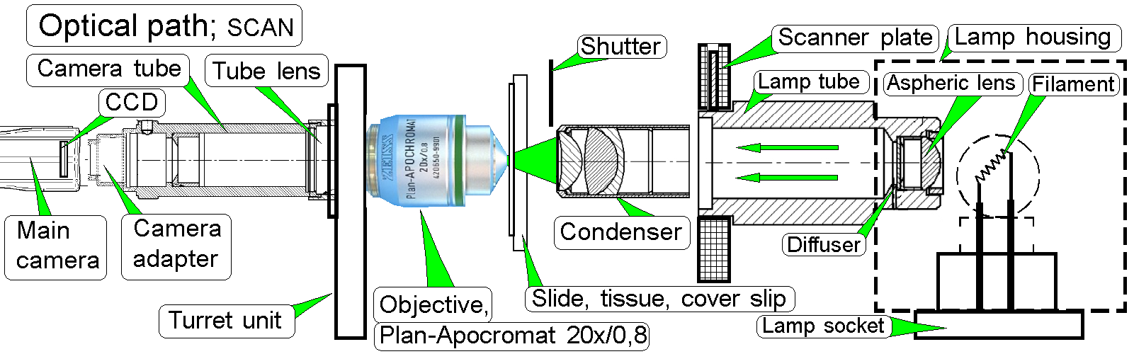
· To reach an
optical path without lost of light intensity, the optical axis is arranged
straight, without mirrors.
Optical path of the Pannoramic DESK
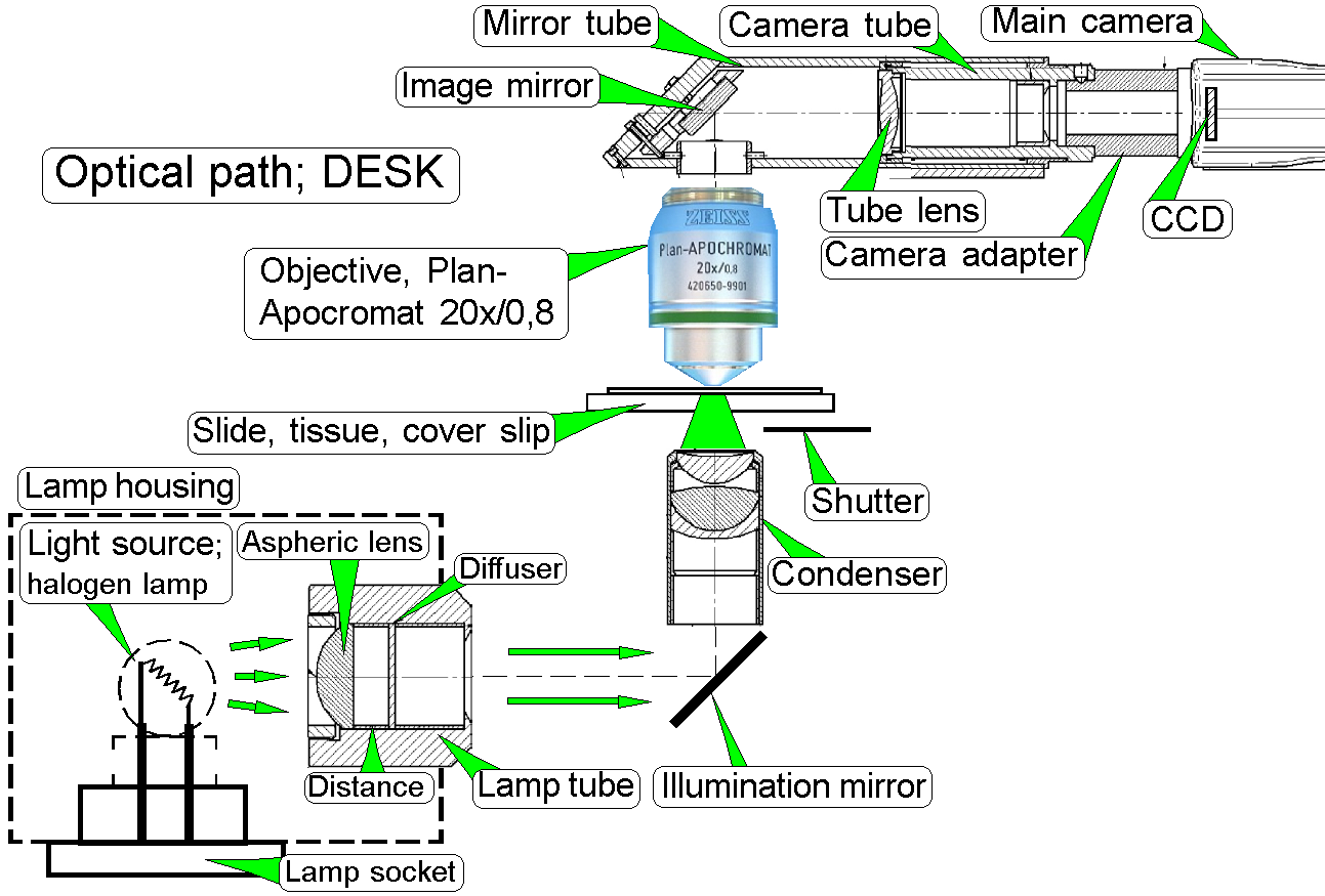
· To reach a small,
compact desktop scanner, the image path as well as the illumination path is
reflected in an angle of 90degrees with the illumination mirror and the image
mirror as well.
Optical path of the Pannoramic MIDI
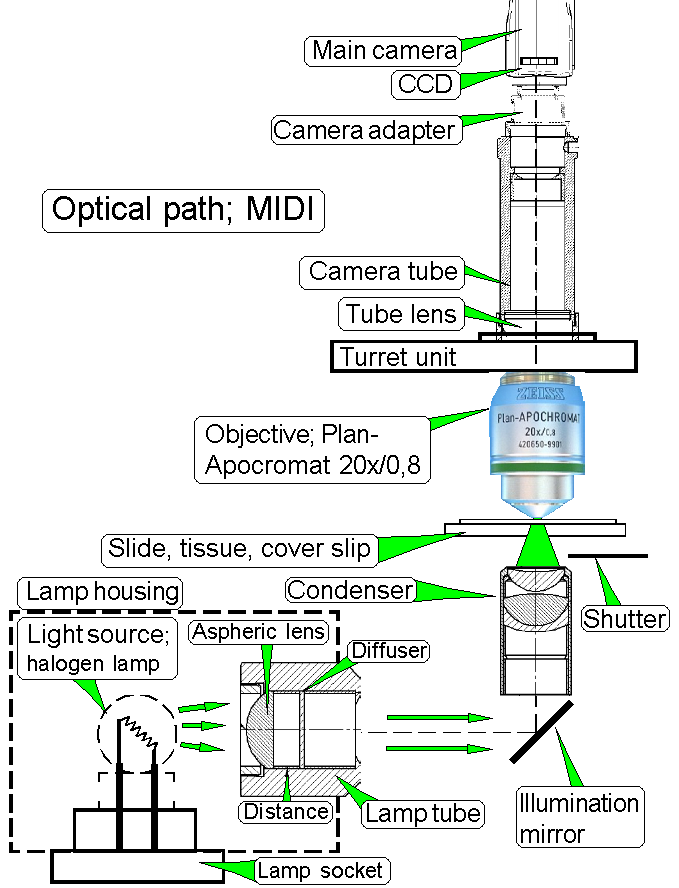
· Only the
illumination path uses an illumination mirror, the image path is straight.
Brightfield
illuminated optical path of the SCAN MIDI and DESK
The emitted light of the light source
is collected by the aspheric lens and the produced parallel light rays are send
to the illumination mirror (DESK,
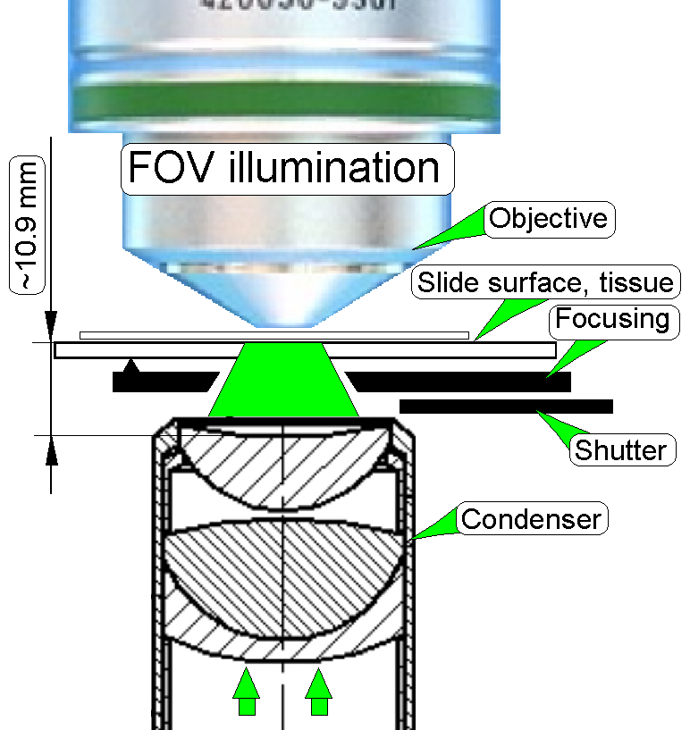
The condenser concentrates the light
to that area of the tissue that is just observed by the objective pupil and the
scan camera; the condenser illuminates the field of view (FOV).
The light travels thru the tissue
and is collected by the objective.
Into the space between objective and
tube lens optical components can be inserted, like the fluorescent filter block
(SCAN,
The image, created by the objective
together with the tube lens can be modified in its size by using camera
adapters with different magnifications.
The reached magnification, seen by
the CCD of the main (scan) camera is the result of the product of objective
magnification and camera adapter magnification.
Example: If the objective magnification is
20x and a camera adapter with a magnification of 0.63x is implemented, the
resulting magnification is 12.6x.
Remark: The magnification of the camera
adapter can not be varied as desired, the construction of the image path and
the size of the CCD of the used camera limits the usable camera adapter
magnification.
The CCD of the camera transforms the
incoming light into electrical charge, this is read by the camera electronics
and the composed data stream (the image) is transferred to the software.
Introduction
of components
A detailed description of the used components can be found in the
chapter “Components and
construction” of the file “Optics_and_Illumination.htm”
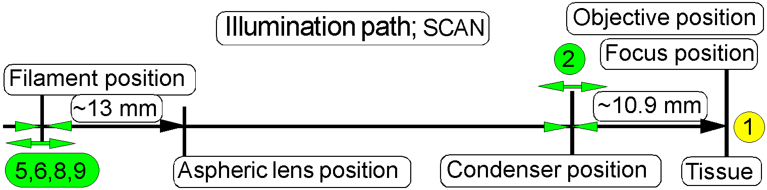
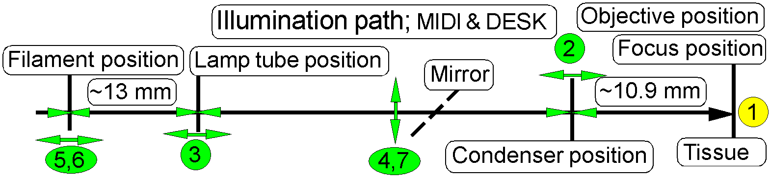
Halogen lamp
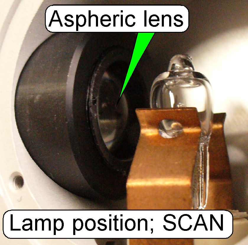
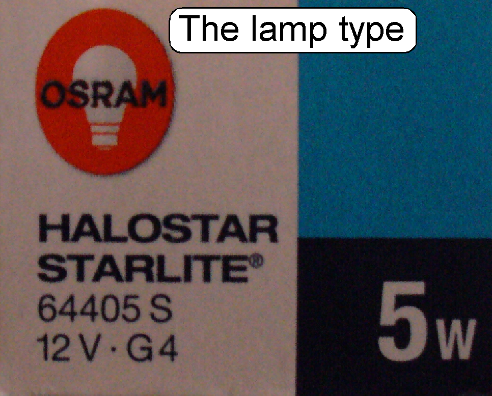
· The focus position of the aspheric lens in relation to
the filament of the lamp is ~13 mm.
· The best illumination quality will be reached if the
center of the filament is in the focus position of the aspheric lens!
· During movements of the microscope or during the aging
process of the filament, the optimal focus position of the aspheric lens may be
lost, resulting in improper illumination of the FOV.
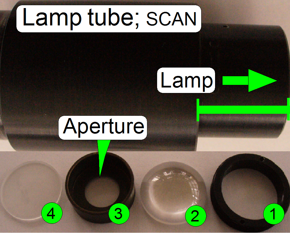
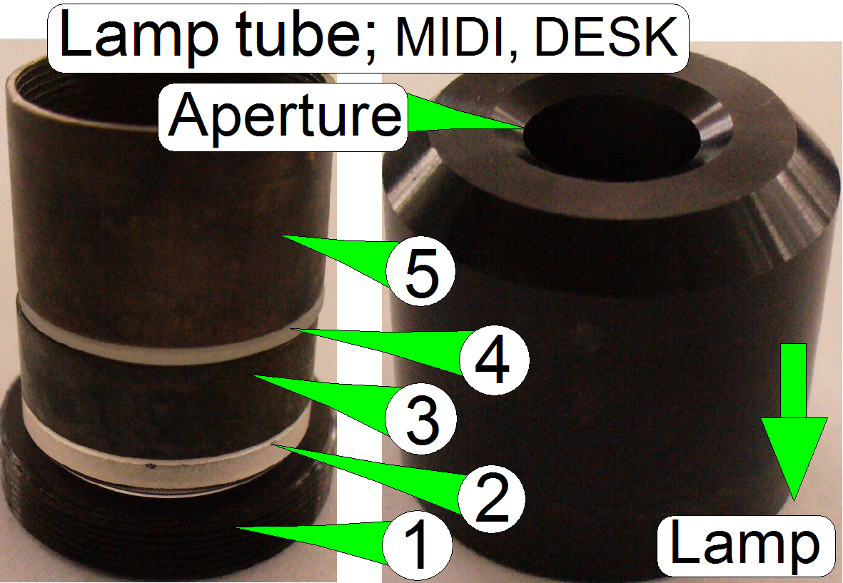 In microscopes the illumination
of the tissue is very important. The lamp (illumination) tube contains the
optics to produce light with a high density and coherent rays; so, the field of
view can be illuminated evenly.
In microscopes the illumination
of the tissue is very important. The lamp (illumination) tube contains the
optics to produce light with a high density and coherent rays; so, the field of
view can be illuminated evenly.
1.
Ring nut
2.
Aspheric lens.
The focus position is ~13 mm.
3.
Distance ring
“a”; SCAN: the aperture is
near to the diffuser
4. Diffuser
5. Distance ring “b”
Illumination mirror;
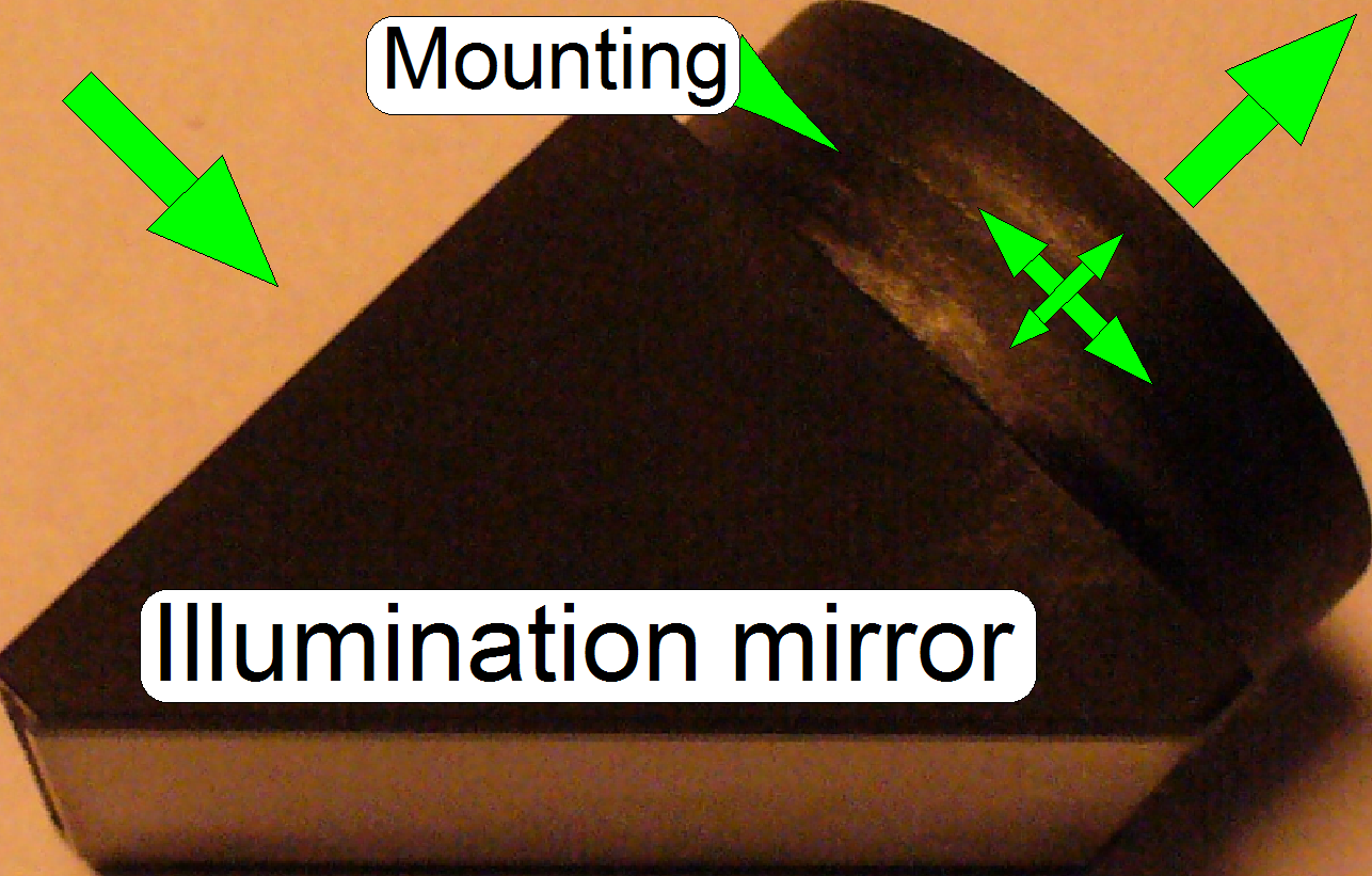 Because in
·
For best
illumination results the mirror position must be adjusted.
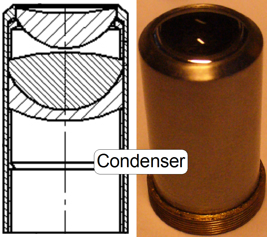 The condenser concentrates the incoming light to the
field of view (FOV).
The condenser concentrates the incoming light to the
field of view (FOV).
Because the size of the illuminated
part of the tissue is critical, the condenser position can be adjusted; the
focus position is 10.9mm nominal.
Remark
The best illumination results would be reached if we would use an
objective also to illuminate the field of view; but because objectives are very
expensive, a condenser is used.
· In view of optical
aspects we can say, the condenser is a simplified objective.
 In microscopes, the objective gathers the light,
emitted from the tissue to be observed and focuses the rays to produce an image.
The character of the objective is given by the magnification and the numerical
aperture.
In microscopes, the objective gathers the light,
emitted from the tissue to be observed and focuses the rays to produce an image.
The character of the objective is given by the magnification and the numerical
aperture.
The position of the objective and
the distance to the tissue is very important to produce a focused (sharp)
image. Because in Pannoramic microscopes this distance can be modified by
moving the tissue position on the Z-axis (focusing) both positions are
important, the objective position and the nominal focus position.
Remark
In the standard version of SCAN,

On the scale of the 40x
objective, the thickness of the cover slip should be selected.
·
If the real thickness of the cover slip differs from the
selected / adjusted value, the quality of the scanned FOV may be reduced!
 Objective
and condenser
Objective
and condenser
The parallel light rays, created by the aspheric lens and the diffuser are
focused by the condenser to the field of view, observed by the objective pupil.
To reach a sharp (focused) image, the slide is moved in Z-direction
toward or away from the objective pupil, in the defined focus range.
· Because the tissue
may vary in thickness, the actual focus position must be checked / adjusted
always during the sample scan process.
·
 On the side, near to the objective, the tube lens is
situated; this performs the image (together with the objective).
On the side, near to the objective, the tube lens is
situated; this performs the image (together with the objective).
·
Into the space
between objective and tube lens further optical components can be inserted,
like the filter block for the fluorescent scan or an image mirror like in the
DESK.
·
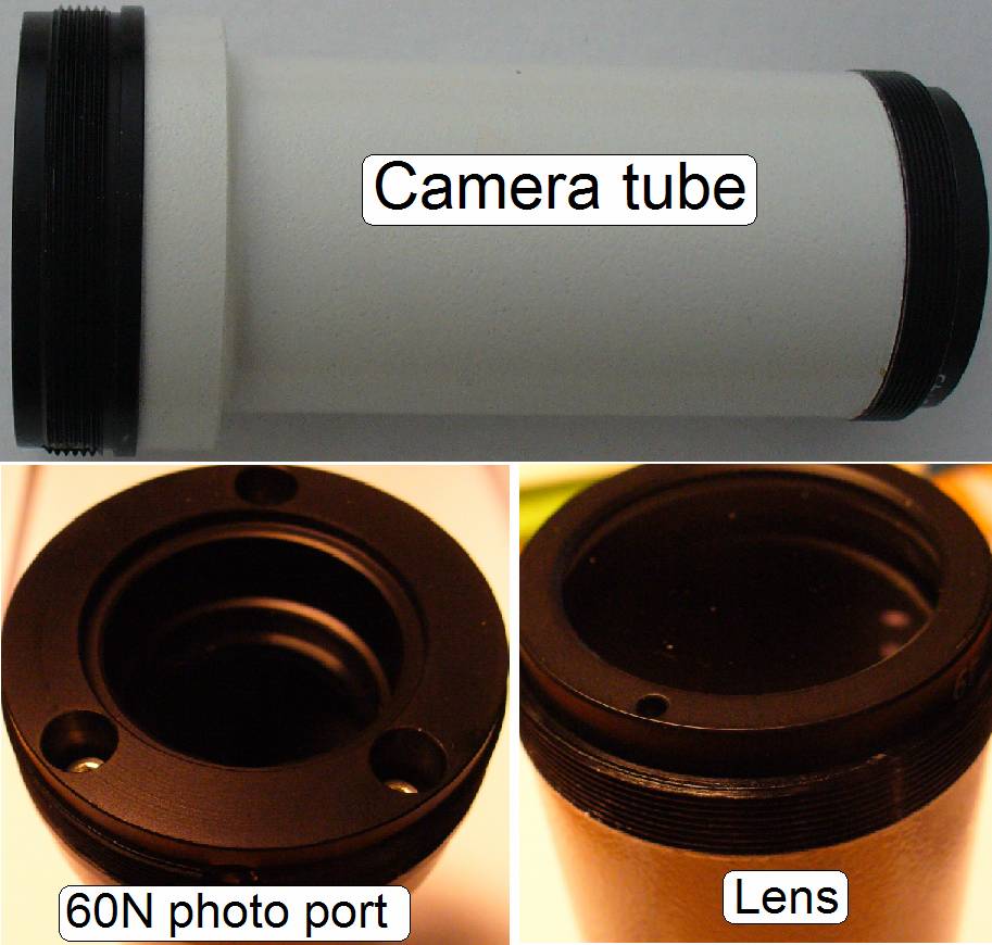
For best image
quality, the tube lens should be mounted into the camera tube until it stops!
·
The camera
adapter 60 C1” can be also connected to the 60N interface.
·
The camera tube
of the DESK is equipped with an adapter 60 C1” so a 60N interfaced camera
adapter can not be connected.
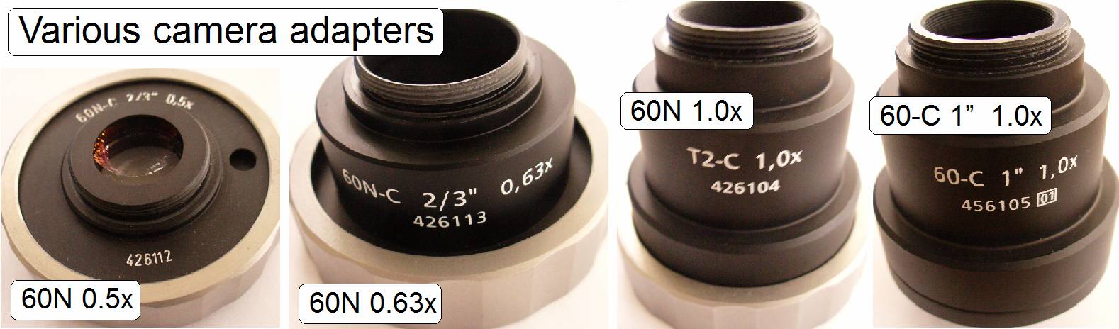 The camera adapter
is situated between the camera tube and the scan camera and offers the
possibility to insert lenses or other optical means like filters into the image
path.
The camera adapter
is situated between the camera tube and the scan camera and offers the
possibility to insert lenses or other optical means like filters into the image
path.
If lenses are inserted, the camera adapter modifies the image size and
the magnification.
The usable magnification of the camera adapter depends on the scan
camera’s CCD size and its resolution and the construction of the optical path.
See also: Camera adapter
Scan (main) camera
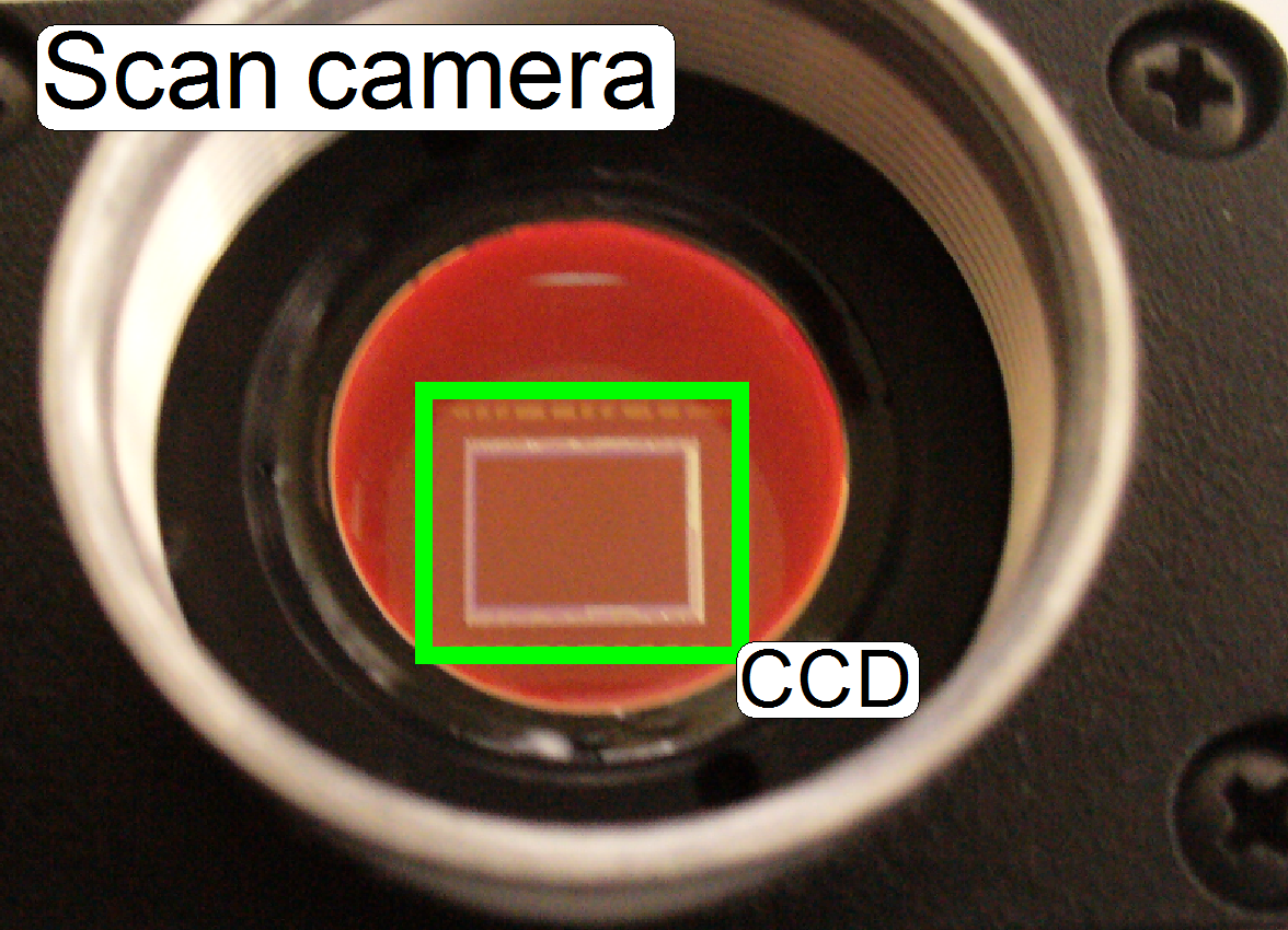 The charge coupled device (CCD) of the scan camera transforms
the incoming light (the image) into electrical charge; and this is read out by
the electronics of the camera.
The charge coupled device (CCD) of the scan camera transforms
the incoming light (the image) into electrical charge; and this is read out by
the electronics of the camera.
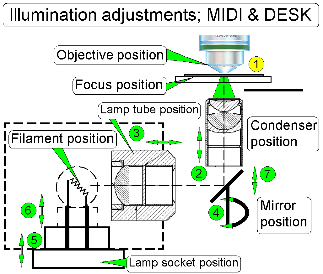
Illumination path adjustments
SCAN
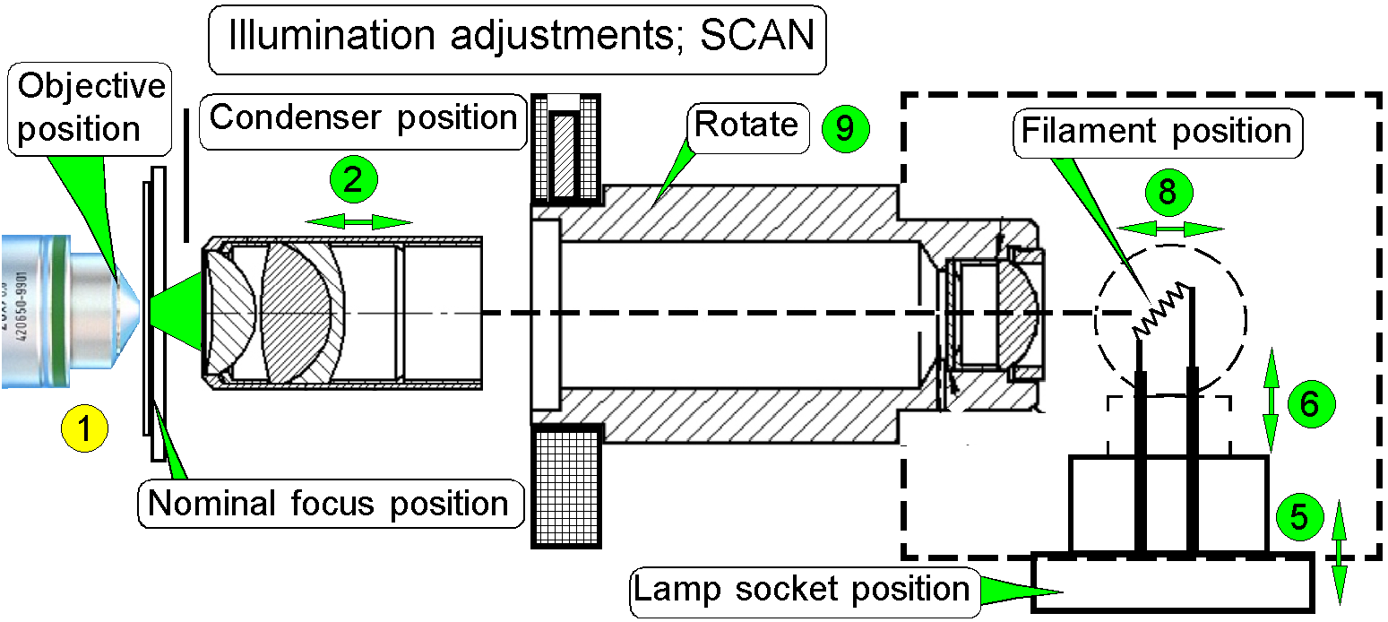
![]() Set the nominal focus position to 1600 steps and
adjust the objective position until the tissue is in focus; then hold the
distance between objective and tissue constant during the entire adjustment
procedure.
Set the nominal focus position to 1600 steps and
adjust the objective position until the tissue is in focus; then hold the
distance between objective and tissue constant during the entire adjustment
procedure.
Use always the found number of focus steps!
![]()
Adjust the condenser position
![]()
Adjust the lamp socket (filament) position
Do the adjustment of previously
named components again as required; steps 2 - 5.
![]() Adjust the lamp position in relation to the socket (pull
the lamp out of about 1mm),
Adjust the lamp position in relation to the socket (pull
the lamp out of about 1mm),
![]() Adjust the mirror position in relation to the scanner
plate (pull the mirror out of about
Adjust the mirror position in relation to the scanner
plate (pull the mirror out of about
![]() Bend the lamp toward the lamp tube (Scan only, because
the tube distance can not be adjusted).
Bend the lamp toward the lamp tube (Scan only, because
the tube distance can not be adjusted).
![]() Loosen the mounting bolt for the Lamp tube (if SCAN:
loosen the mounting bolt for the lamp housing also) and rotate the lamp tube.
Some times there can be reached more proper results in the SCAN.
Loosen the mounting bolt for the Lamp tube (if SCAN:
loosen the mounting bolt for the lamp housing also) and rotate the lamp tube.
Some times there can be reached more proper results in the SCAN.
![]() Adjust the objective position and the focus position;
then hold the distance between objective and tissue constant during the entire
adjustment procedure by using always the found number of focus steps!
Adjust the objective position and the focus position;
then hold the distance between objective and tissue constant during the entire
adjustment procedure by using always the found number of focus steps!
![]()
Adjust
the condenser position
![]()
Find the
correct lamp tube position
![]()
Find the
correct mirror position
![]()
Adjust
the lamp socket (filament) position
Do the adjustment of previously
named components again as required; steps 2 - 5.
![]() Adjust the lamp position in relation to the socket
(pull the lamp out of about
Adjust the lamp position in relation to the socket
(pull the lamp out of about
![]() Adjust the mirror position in relation to the scanner
plate (pull the mirror out of about
Adjust the mirror position in relation to the scanner
plate (pull the mirror out of about
![]() Bend the lamp toward the lamp tube (Scan only, because
the tube distance can not be adjusted).
Bend the lamp toward the lamp tube (Scan only, because
the tube distance can not be adjusted).
![]() Loosen the mounting bolt for the Lamp tube (if SCAN:
loosen the mounting bolt for the lamp housing also) and rotate the lamp tube.
Some times there can be reached more proper results in the SCAN.
Loosen the mounting bolt for the Lamp tube (if SCAN:
loosen the mounting bolt for the lamp housing also) and rotate the lamp tube.
Some times there can be reached more proper results in the SCAN.
![]()

Adjust the objective and focus position
 This Adjustment assumes that the focus unit is
adjusted, except the objective position.
This Adjustment assumes that the focus unit is
adjusted, except the objective position.
· For further information and adjustments see “The focus unit”.
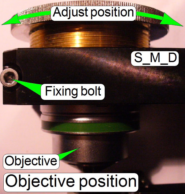
1.
Start the slide
scanner program, insert a slide with a tissue and create a live view; the known
focus position of the tissue should be nearly to 1600 steps, the nominal focus
position.
2.
Produce a live
view and set the focus motor position to 1600 steps (or the known focus
position).
3.
Loosen the
objective mounting by loosening the objective fixing bolt.
4.
Drive the
knurled objective nut so, that the objective moves toward the tissue or away
from it until the focus is found.
5.
During
tightening the fixing bolt of the objective observe the live view and correct
the objective position as necessary.
6.
With the option
autofocus check the adjustment.
7.
Repeat from
step 2 if necessary.
![]()

Adjust the lamp socket (filament) position
Drive the adjustment bolts “a”, “b” and
“c” in or out, until the optimal position of the filament in relation to the
aspheric lens is found.
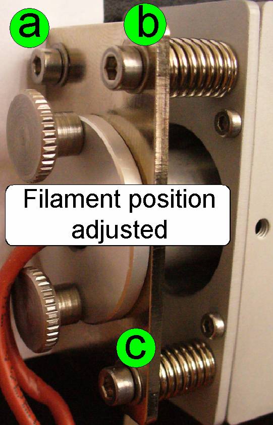
·
Remove the
knurled bolts of the lamp socket mounting and modify the lamp position in
relation to the socket if required or to exchange the lamp.
The entire image path adjustment
includes the adjustment of the following parts:
1. The objective
position
This
adjustment ensures that tissues with different thicknesses can be scanned in focus;
of course, it was adjusted previously for the brightfield illumination, but the
objective position should be checked / adjusted again. If the objective
position is incorrect, the tissue or parts of it can not be scanned in focus;
see also “Check the optical path adjustments”.
2. The camera tube
position
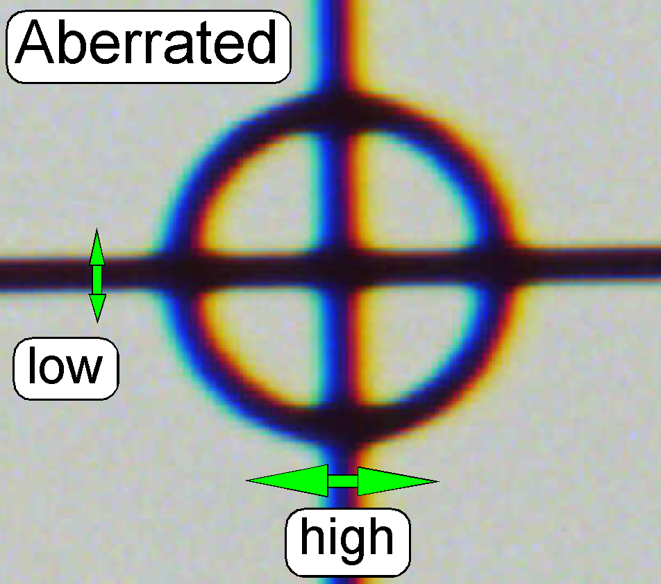
The
position of the camera tube (lens) affects the color trueness of the scanned
tissue; the chromatic aberration becomes visible in more blue, and more red or
yellow colored cell borders on the opposite sides; see also “Chromatic
aberration” and “Adjustments”.
If
the camera rotation angle is out of the limits, the stitching is not correct
and the borders of the FOV’s becoming visible in the virtual tissue with the
viewer program, the sample does not fit on the border of the FOV; see also
“Stitching’.
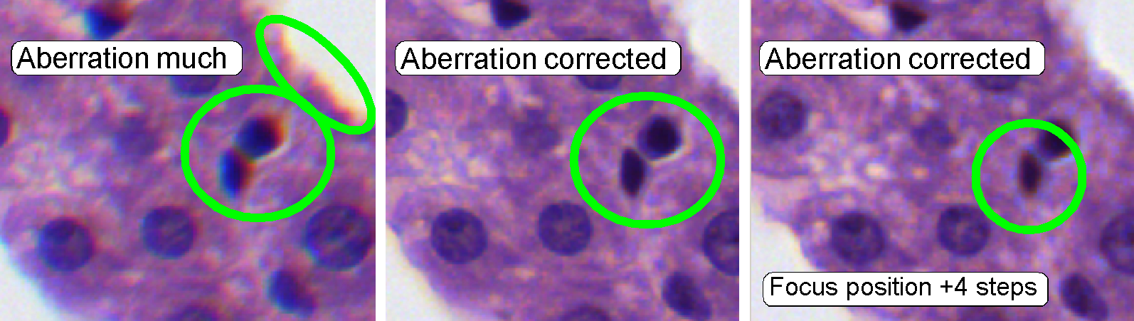
 The appearance of
chromatic aberration can be divided into two main reasons:
The appearance of
chromatic aberration can be divided into two main reasons:
1.
The used materials (the composition of the glass) in
the lens system; different wavelengths of light will be focused to different
positions; and
2.
The arrangement of the lenses to each other
(centermost), with other words, the straightness of the optical path (lens
system).
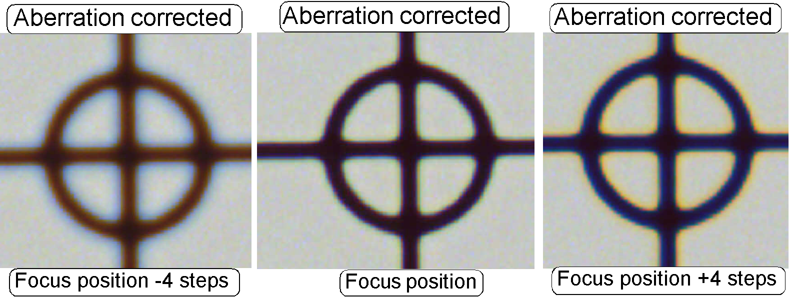 The adjustment of the chromatic aberration is done in
the real focus position and in the center of the FOV to be observed. To check
the result of the adjustment, the focus position can be modified by some steps in
positive or negative direction. In this way, the correctness of the adjustment
becomes more visible. If the yellow color occurs evenly on the inner and outer
part of the circle in the center, the adjustment is acceptable; see “Focus
position +4 steps”.
The adjustment of the chromatic aberration is done in
the real focus position and in the center of the FOV to be observed. To check
the result of the adjustment, the focus position can be modified by some steps in
positive or negative direction. In this way, the correctness of the adjustment
becomes more visible. If the yellow color occurs evenly on the inner and outer
part of the circle in the center, the adjustment is acceptable; see “Focus
position +4 steps”.
The images was done in the focus
position of the live view, except otherwise specified and with a zoom factor of
2,73
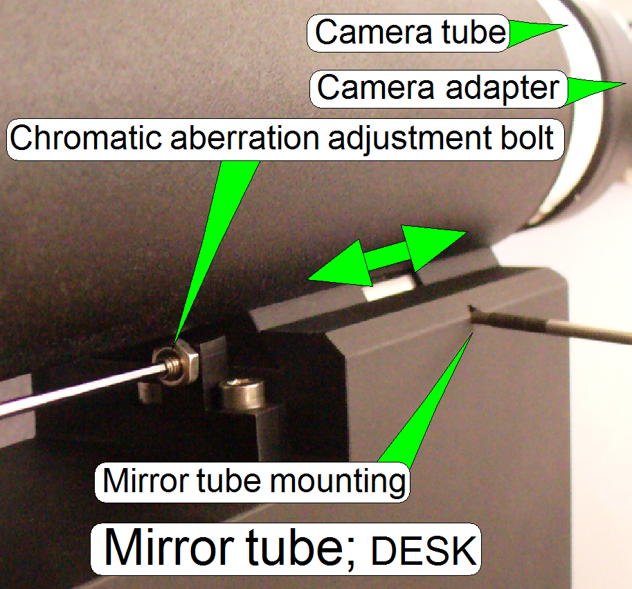
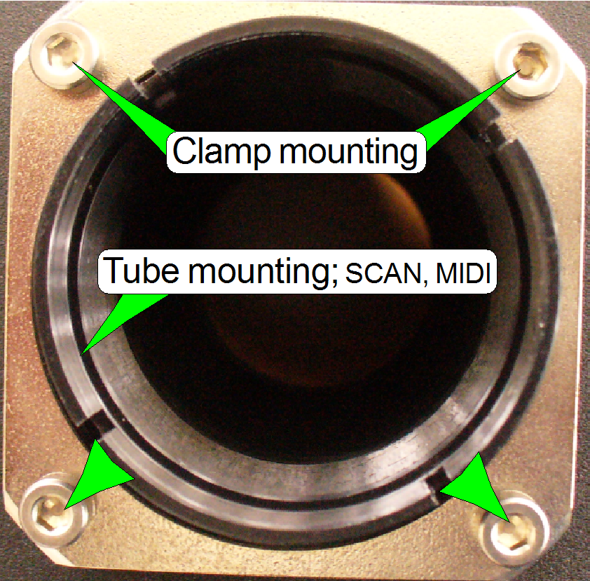 The tube is mounted so, that the correct position can be
adjusted; with this adjustment the chromatic
aberration is corrected / minimized.
The tube is mounted so, that the correct position can be
adjusted; with this adjustment the chromatic
aberration is corrected / minimized.
·
For
adjustments, loosen the four mounting bolts to make the tube mounting barely
moveable.
·
See also
“Adjustment procedures”.
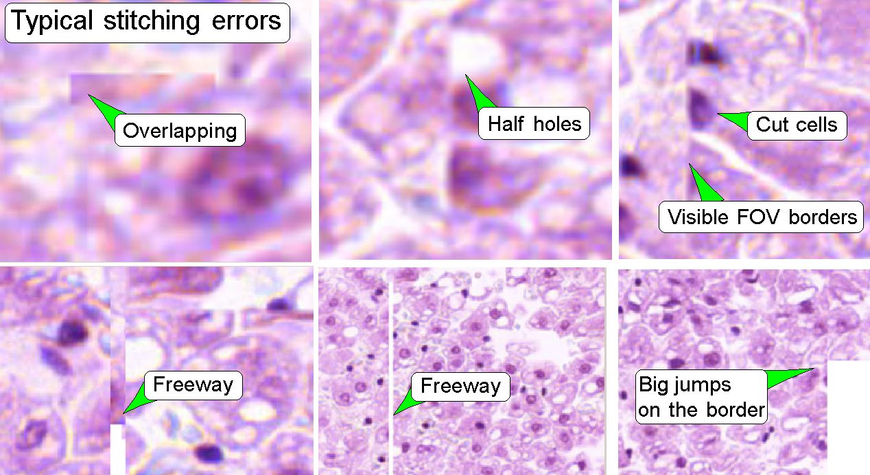 Stitching errors have two main reasons:
1.
Improper
adjusted camera rotation angle and
2.
The hysteresis
in Y-direction is too much.
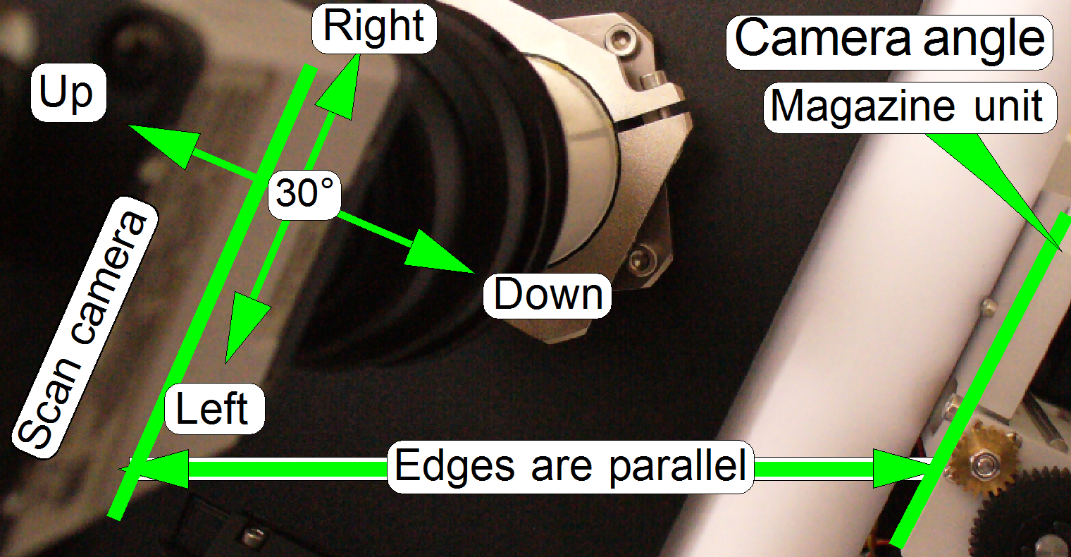
The camera angle becomes important
during stitching. If the angle of the scan camera is out of the limit, the
stitching does not working well, so the FOV’s, seen with the viewer does not
fit to each other. An acceptable camera angle has less then +-0.5 degrees
deviation from zero.
If the camera angle is correct and
stitching errors occurs, check the hysteresis in Y-direction.
·
See the next
chapter “The
Y- and X-hysteresis” and also “The
X-Y-stage unit”
Remark
The shown stitching errors existing
always parallel inside of the same scanned tissue, it means, if one occurrence
is found, all others can also be found on different areas of the same scanned
tissue.
Camera changer
(the double adapter 60N)
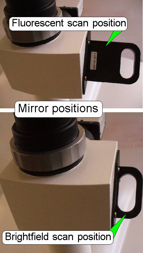
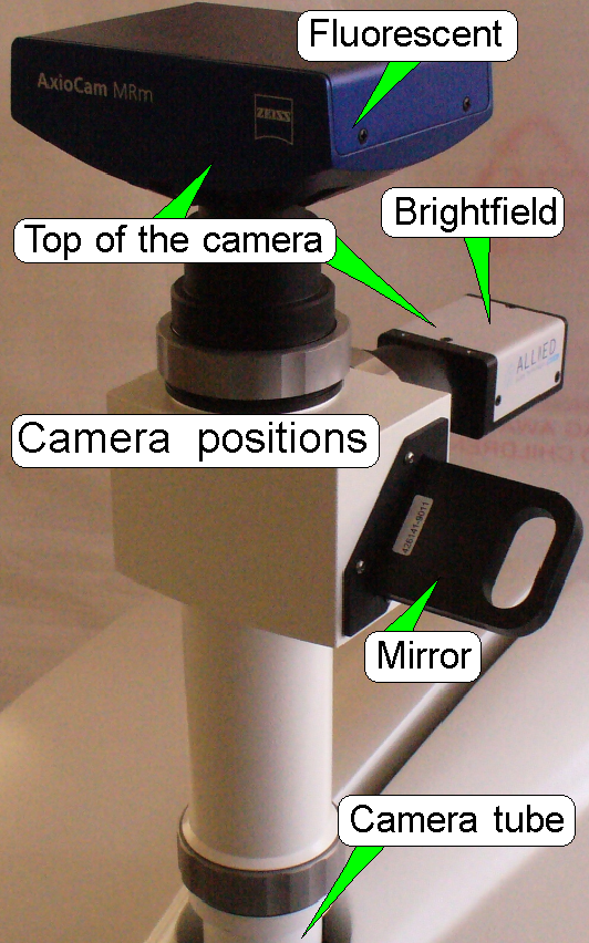
The manual camera changer (the
double adapter 60N is a product of Carl Zeiss ltd.) allows the use of different
cameras for brightfield illumination scan and fluorescent illumination scan; it
may be a component of the Pannoramic SCAN or the Pannoramic MIDI microscope
likewise.
· The camera (mirror
position) is selected manually, before the appropriate scan session will be
started.
End; you may continue with the
tour 3: Optics
of the P250